Abstract
With the large-scale development and application of offshore wind resources, the proportion of powered electronic equipment in power systems is increasing, which leads to the reduction of traditional mechanical inertia and system oscillation. To solve the above problems, this paper takes the grid connected converter of an offshore full power fan as the research object, deduces the “inertia” expression and physical significance of its inner and outer loop controller, and compares it with the mechanical inertia motion equation to obtain a unified mathematical expression. On this basis, combined with the control bandwidth and Rouse criterion, the discrimination method of system stability is proposed, and the correlation of the internal and external control parameters of the full power fan grid connected converter and its influence on the grid connected stability of offshore fans are explained according to the derived judgment expression. Finally, the correctness and scope of application of the theoretical analysis and judgment method are verified by PSCAD/EMTDC time-domain simulation software.
1. Instruction
The resource of wind is rich in China. Distributed wind power generation has the advantage of small volume and being close to the load center, making wind power an essential part of the distribution network in the future [1,2]. However, large-scale wind power would reduce the equivalent inertia of the distribution network, causing oscillation problems [3,4]. Recently, oscillation instability in different frequency ranges has occurred in many wind farms at home and abroad [5,6,7], which brings significant challenges to the safe and stable operation of the power system and has caused substantial economic losses and negative effects on society. Based on this, it is urgent to investigate the system oscillation problem caused by the Grid Connected Converter (GCC).
The Permanent Magnet Synchronous Generator (PMSG) with multiple magnetic poles does not need to rely on a gearbox for transmission, reducing maintenance costs. PMSG is widely used in distributed generation (DG) for this reason. The research shows that the various oscillation problems of PMSG mostly originate from changes in system parameters, and it is considered to be oscillatory instability caused by small disturbances [8]. At present, two methods are mainly adopted to analyze the small-signal stability: the small-signal average model and the impedance method. For example, reference [9] adopted the harmonic state-space (HSS) modeling approach to study the instability mechanism of the interconnected system. Reference [10] built impedance models of PMSG and HVDC rectifiers based on the harmonic linearization method and analyzed the possible unstable operating range of the system from the perspective of the frequency domain. Reference [11] adopted eigenvalue analysis theory to study the influence of parameters of the converter controllers and the short-circuit ratio of voltage source converter-based HVDC oscillatory modes. Reference [12] constructed a closed-loop frequency domain model of modular multilevel converter (MMC) and analyzed the effect of a zero-sequence circulating current controller on the stability of MMC-HVDC. Reference [13] utilized the state space method to model the dominant mode of PMSG. Reference [14] derived the impedance model of the grid-connected renewable energy system (GCRES). Reference [15] mainly focused on the impact of wind turbine grid-side controller’s parameters on its AC-side impedance characteristics. Reference [16] studied the influence of wind turbine output power and DC converter’s control parameters on system stability based on mode analysis.
However, the impedance method proposed in the above literature cannot accurately determine the stability margin of the GCRES with PMSG, and the solution of the full-order state matrix model is complicated. In particular, when the number of nodes is large, the full-order state matrix model cannot be solved.
To solve these problems, this paper proposes a reduced-order model to directly clarify the impact of PMSG controller parameters on small-signal stability based on the theoretical analysis of damping characteristics and inertia hysteresis in the controller. Lessons are drawn from the unit oscillation model and dynamics analysis research in a circuit and synchronous generator (SG) system. Since the dynamic characteristics of the PMSG are associated with the inertia of the controller, the stability limit consisting of the PI gains is derived. The derived stability limit is computationally simple and does not require a full-order model of the PMSG. Therefore, it can be used to approximately assess the instability risk of the PMSG caused by the inertia of the controller more conveniently. In addition, derivation of the stability limit reveals why the PMSG may become unstable due to the inappropriate selection of the controller’s parameters. Furthermore, the effectiveness of the proposed methodology is verified through PSCAD/EMTDC time-domain simulation.
Compared with existing works in the concerned research field, the major contributions of this paper can be summarized as follows:
- (1)
- We propose a reduced-order model to directly clarify the impact of PMSG controller parameters on small-signal stability based on the theoretical analysis of damping characteristics and inertia hysteresis in the controller.
- (2)
- The stability limit consisting of the PI gains is derived based on the inertia of the controller. The derived stability limit is computationally simple and does not require a full-order model of the PMSG. Therefore, it can be used to approximately assess the instability risk of the PMSG caused by the inertia of the controller more conveniently.
2. Inertia Analysis of Mechanical Motion
According to the macrophysics theory, inertia is the inherent property of an object by which it continues in its existing state of rest or uniform motion in a straight line. It represents the resistance degree of an object to changes in motion state. The classic mechanical motion shows that different objects have different inertia. The motion equilibrium point of a coupled system composed of different objects is not synchronized with the equilibrium point of the controlled state quantity, which will cause the coupled system to oscillate.
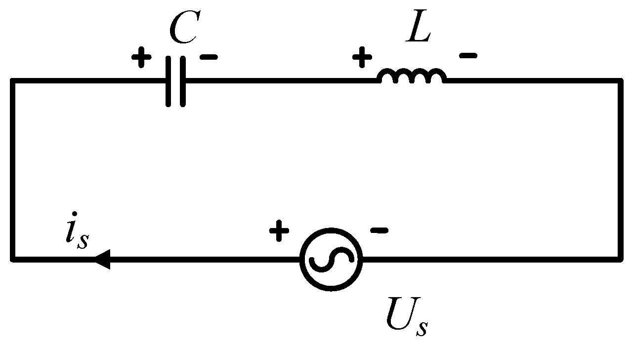
Similar to the mechanical motion, the control of power electronic components also has inertia, which manifests as the output lags the input. For example, inductive elements have magnetic inertia, which manifests as current lags voltage by π/2. Capacitive elements have electric field inertia, which manifests as voltage lags current by π/2 [17], as shown in Figure 1. Thus, when the second derivative of the current is equal to 0 near an equilibrium point of the system, the first derivative of the current is not equal to 0. This results in electromagnetic oscillation.

Figure 1.
The circuit consists of an inductor and a capacitor shown inertia.
According to the Kirchhoff’s current law, the mathematical expression of a second-order circuit composed of the inductor and the capacitor can be derived from Figure 1, shown as follows:
Equation (1) reflects the dynamic response of the state variable ΔX at the equilibrium point, as well as the inertia and damping characteristics of the system, where G1 = 1/, G2 = 1/.
3. Derivation and Analysis of PMSG Controller Inertia
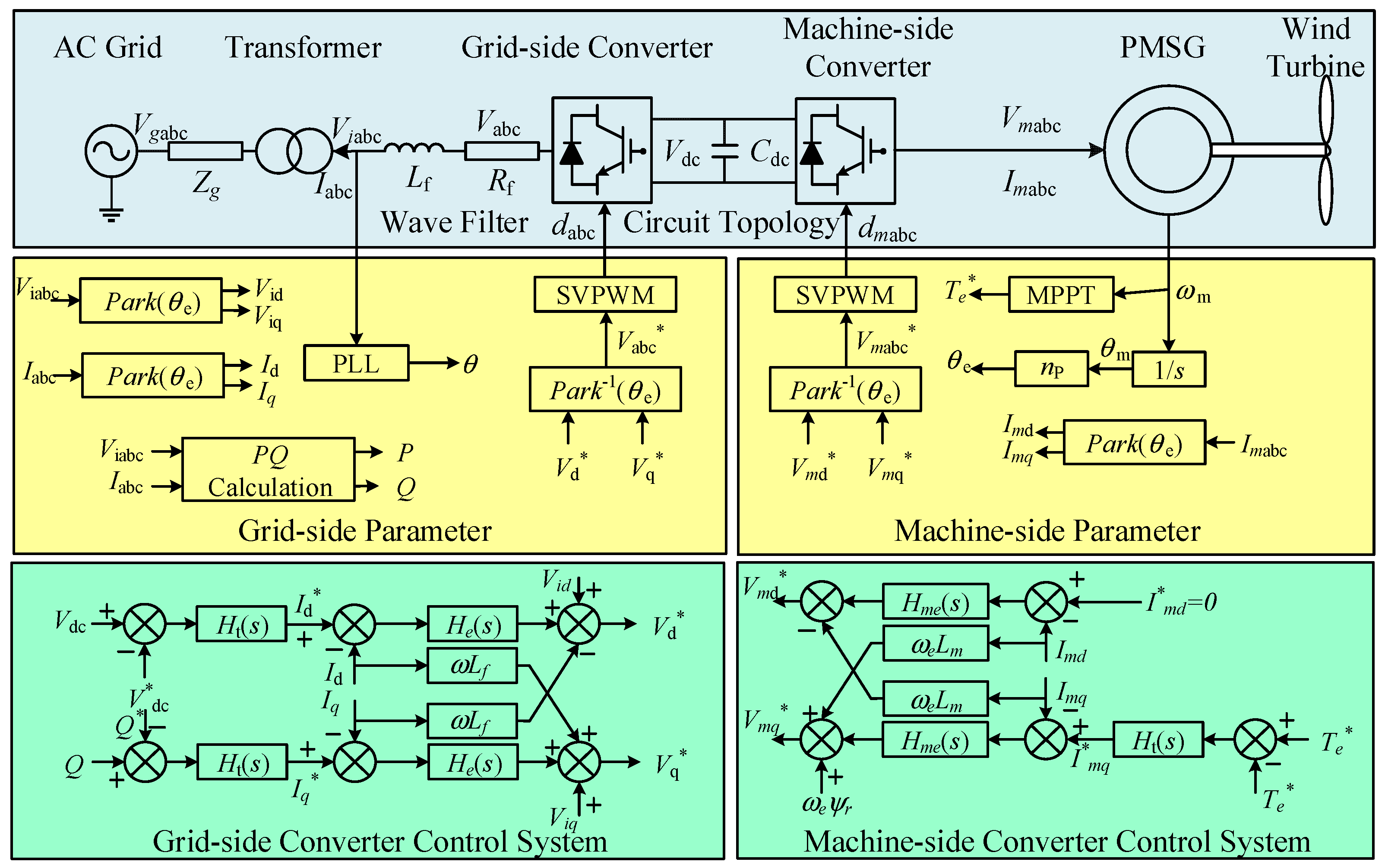
Due to the influence of inductive components, capacitance, and control delay, the inner loop current of the PMSG-GCC exhibits inertia characteristics, which may cause the system with PMSG to oscillate. The physical nature of this phenomenon is the hysteresis effect of feedback control. A typical single PMSG model considered in this paper consists of a closed-loop (outer and inner loop) controller and an LC filter, as depicted in Figure 2, where Lg and Cf are ac-side filter inductance and capacitor, respectively, and Vdc is the dc-side voltage. Phase voltages are expressed as va, vb, and vc, while phase currents are ia, ib, and ic, and ma, mb, and mc are the modulating (reference) signals for the pulse width modulation (PWM).
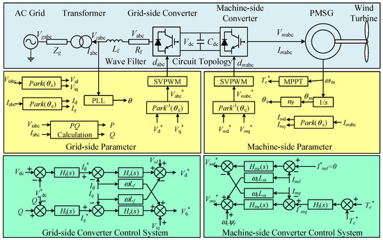
Figure 2.
The inner and outer control loop of PMSG.
When the system is three-phase balanced, the synchronous generator voltage loop equation expression under the d-q axis is obtained as follows:
where ωr is the electrical angular velocity of a synchronous generator; Ψds and Ψqs are the d-axis and q-axis flux linkage, respectively.
When R ≈ 0, Ψds, and Ψqs can be expressed as follows:
where Ψr is rotor flux linkage; Ld and Lq are the stator d-axis and q-axis inductance, respectively.
The d-axis and q-axis cross-coupling variables can be regarded as disturbance terms, and mathematical compensation could be carried out in the control strategy when the control relationship between ΔνS and ΔiS is studied [18].
When PMSG is controlled using a zero d-axis current control strategy (ZDC), ids equals 0, and electromagnetic power output by PMSG can be obtained as follows:
It can be seen from Figure 3 that the relationship between the deviations of the external loop output and the power is obtained as follows:
where kp1 and ki1 are the proportional gain coefficient and integral constant, respectively, of the external loop PI controller. Take the derivative on both sides of Equation (5) as follows:
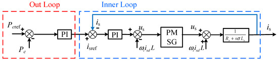
Figure 3.
The vector diagram of PMSG controlled by ZDC.
Equation (7) can be obtained from the closed-loop control logic block diagram of PMSG.
where kp2 and ki2 are the proportional gain coefficient and integral constant, respectively, of the inner loop PI controller; Zl is the impedance of the ac line, and Zl = R + ωrLg.
Combining Equations (6)–(8) can be derived as follows,
Equation (8) can be simplified as follows:
where:
Comparing Equations (1) and (9), the inertia equation considering damping could describe the characteristics of the output of the PMSG-GCC controller. Due to the inductance and capacitor affection and the controller delay, the current reference produced by the active power displays “inertia” characteristics similar to the synchronous generator, and it provides an oscillation mode for the system. As a result, there will be a certain deviation in the actual output, and the deviation signal of the controller cannot be converted entirely into control action in time. This is reflected in the inertia of the controller [19]. The analysis shows that the hysteresis effect could be expressed via the second-order equation. Hence, the PMSG control output characteristics are basically consistent with the inertia equation (Equation (10)).
According to the automatic control theory, after a state variable is disturbed, if the motion characteristics of the state variable are bounded and convergent, the system is stable. On the contrary, if the motion characteristics of the state variable are unbounded or divergent, the system will be unstable. If the motion characteristics of the state variable are bounded but not convergent, it is a critical steady-state. According to the Rouse–Hurwitz criterion, the system is stable when the coefficients G3 > 0 and G4 > 0. Based on this, the following criterion can be obtained:
According to the automatic control principle, the PI parameter of PSMG-GCC usually satisfies the stable condition represented in Equation (11). The Equation (12) can thus be obtained as follows,
The following conclusions can be drawn from the above formulas:
- (1)
- The stability of PMSG is related to the impedance of the AC line and the setting value of the controller.
- (2)
- When the inner loop parameter kp2 increases, the inner loop control bandwidth increases and the stability threshold of the outer loop parameter kp1 decreases with other conditions remaining the same.
To sum up, the stability criterion proposed in Equation (12) can estimate the stability domain of the outer-loop control parameters according to the inner-loop control parameters of PMSG and provide a reference for engineering applications.
4. Simulation Results
4.1. Effectiveness of Proposed Stability Criterion
This paper proposes a stability criterion to judge whether the PMSG system is stable. To verify the effectiveness of the proposed stability criterion, three cases representing the different stability situations of the PMSG system with different values of kp1 and dominant characteristic root were assessed, and a comparative analysis is conducted based on these scenarios accordingly.
Specifically, in Table 1, Bond is the stable boundary value calculated via Equation (12). Comparing the value of kp1 and Bond, the stability of the PMSG system can be judged, and the stability criterion results of the system stability using the proposed method is shown in Table 1. In addition, the oscillation modes of the full-order model associated with the PMSG were computed to confirm the stability limit assessed above, and the eigenvalue of the full-order PMSG model with the poorest damping was λi. It can be observed that if kp1 > Bond, the stability criterion shows that the PMSG is unstable, and λi is in the right half of the complex plane, which provides the same conclusion. Otherwise, kp1 < Bond, the PMSG is assessed as stable through the stability criterion, and λi is in the left half of the complex plane. Moreover, when kp1 = Bond, the stability limit shows that the PMSG is in the vicinity of critical stability. However, the eigenvalue λi does not pass through the imaginary, which indicates that the criterion is conservative.

Table 1.
The parameters of PMSG outer loop control.
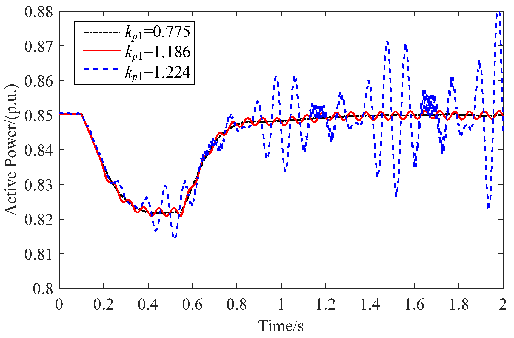
The results of the nonlinear simulation are presented in Figure 4. During the simulation, after the PMSG ran stably for 0.1 s, we reduced the output of the wind farm by 0.03 p.u. The active power output by the PMSG system is illustrated in Figure 4.
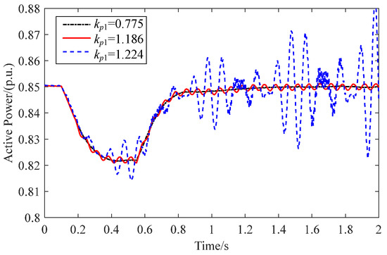
Figure 4.
Relationship of PMSG parameter setting and stability.
It can be seen from Figure 4 that when the value of kp1 is 0.772, the system is in a stable operation state. When kp1 = 1.186, the system oscillates with equal amplitude, that is, the system is in a critically stable state, and the value of Bond calculated via Equation (12) is 1.186. As the value of kp1 further increases (kp1 = 1.224), the system diverges and becomes unstable. This indicates that as the value of kp1 increases, the real part of the dominant characteristic root of the system decreases. When kp1 exceeds the value of Bond, the real part of the dominant characteristic root is greater than 0, and the system becomes unstable. This result is the same as the judgment result obtained using the proposed method in this paper.
4.2. Stable Domain
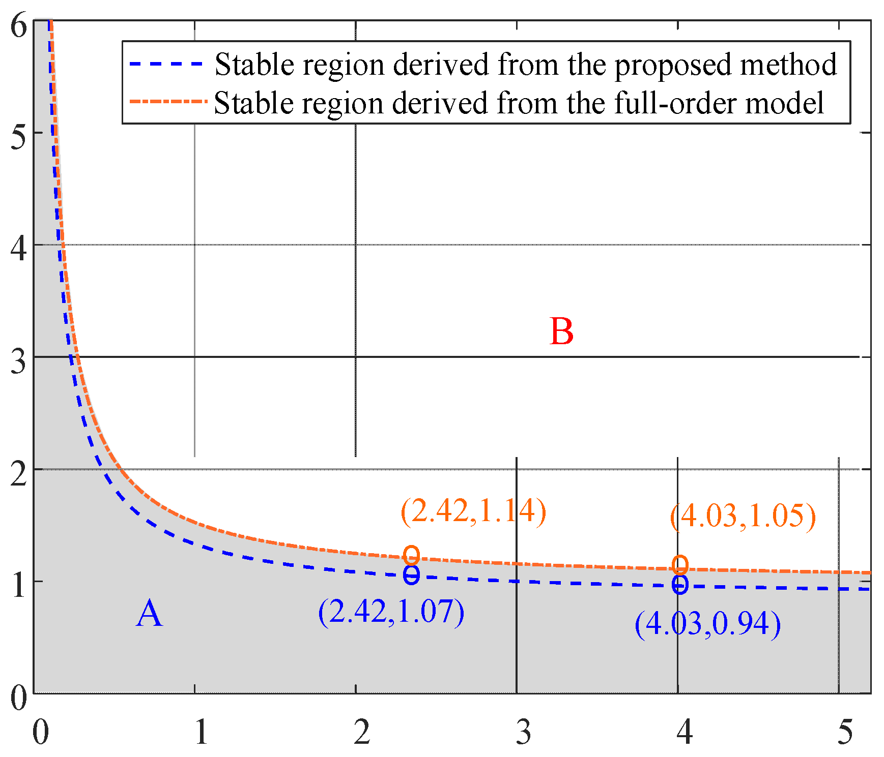
According to the proposed stability criterion (Equation (12)), the stability boundary of the PMSG system with respect to the parameters kp1 and kp2 can be obtained. Based on this, the reference value of the stability domain of the PMSG system can be determined, as shown in Figure 5; the orange line is the stable boundary derived from the full-order model of PMSG, and the blue line is the stable limit calculated by the proposed stability criterion. Figure 5 also indicates that the stable limit calculated by the proposed method is within the stable limit derived from the full-order model, which confirms the correctness of the computation results presented in Table 1.
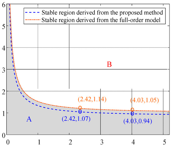
Figure 5.
Stable field.
The area A and B in Figure 5 represent the parameter setting range within which the system is stable and unstable, respectively. The main reason for the system instability is that the value of kp1 is set too large in area B.
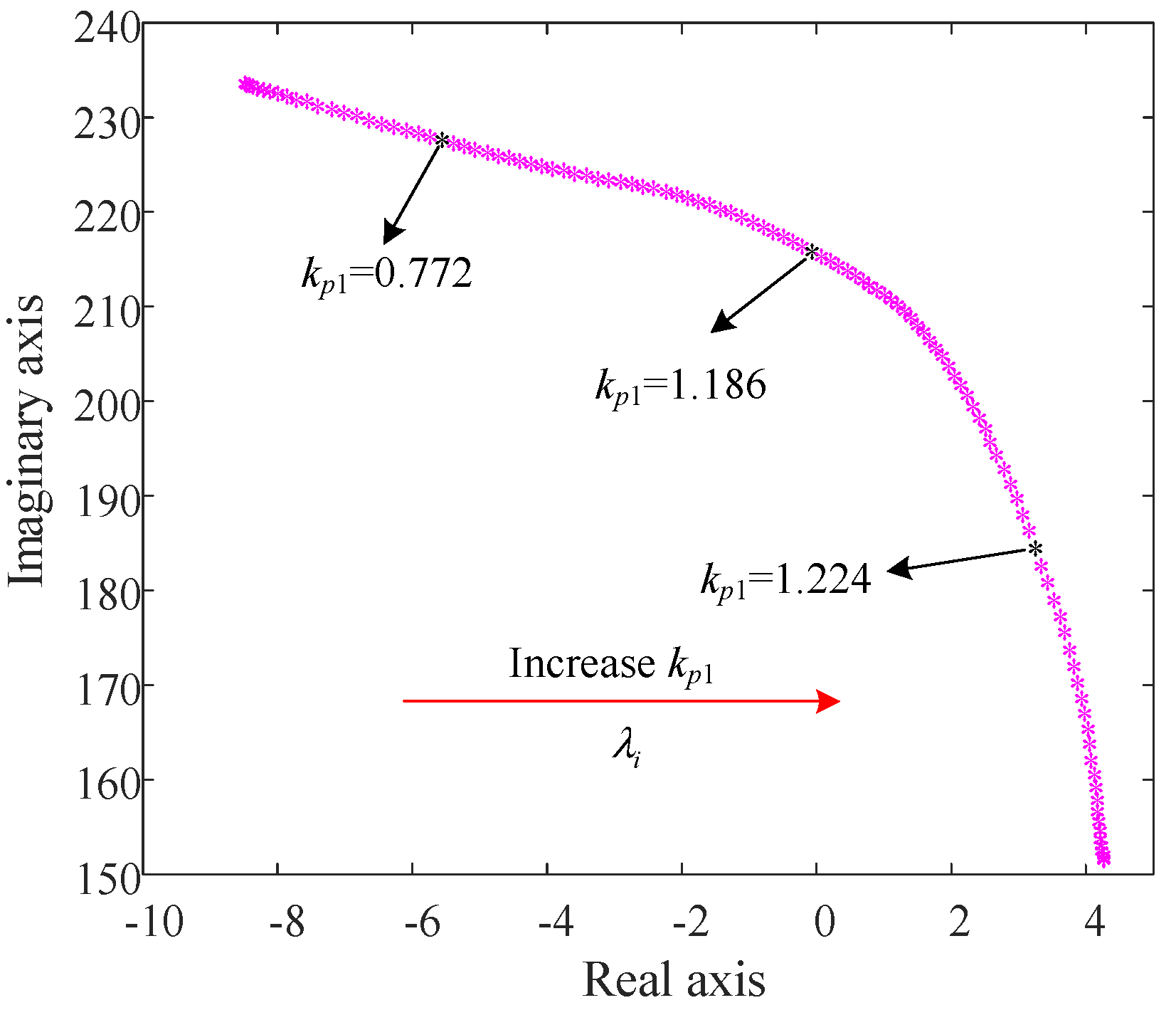
Furthermore, the correctness of the stability limit is validated according to the trajectories of the oscillation modes on the complex plane, as shown in Figure 6. It can be seen that when the parameter kp1 increases from 0.772 to 1.224, the poorest damping eigenvalue for the full-order PMSG model λi moves to the right half of the complex plane.
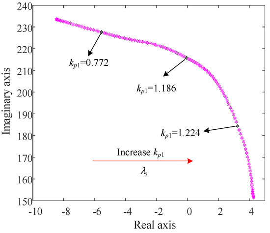
Figure 6.
Trajectories of oscillation mode associated with the poorest damping eigenvalue λi when kp1 increased.
Generally speaking, when designing PMSG control parameters, we first determine the control bandwidth of the inner loop and then set the control bandwidth and related parameters of the outer loop according to the bandwidth and parameters of the inner loop [20]. The transfer function of the PMSG inner loop current control can be expressed as:
Let s = jω; also, the transfer function Ti(s) amplitude is set to 0.707, and the corresponding frequency ω is the bandwidth of the inner loop current control, which can be written as ω = ωi = 2πfi. The relationship between the parameters of the inner and outer loop can be expressed as follows:
where ξi is the damping ratio, Vdc is the voltage value of the system DC side, and kp1 and ki1 are the reference values for the outer loop parameters calculated by the inner loop control bandwidth. The range of the inner loop bandwidth fi was set as 50~280 Hz during the simulation process in this paper.
The above cases study evaluates the correctness of the small-signal stability limit derived in Equation (12), demonstrating that the gains of the PI controller have an impact on the stability of the PMSG. Furthermore, the proposed stability limit can be applied to the selection assessment of the gains of the closed-loop controller for the PMSG.
5. Conclusions
This paper investigated the small-signal stability issue of the PMSG connected to an AC grid based on the inertia analysis of the controller. According to the analysis of damping characteristics and inertia hysteresis in the closed-loop controller, a simple method to detect the instability risk posed by the PMSG controller’s gains was developed on the basis of the SG’s rotor motion and circuit model. Additionally, the analysis and stability limit presented in the study revealed that an inappropriate choice of parameters might provide instability risk to the grid-connected PMSG. In addition, the proposed method enhanced our understanding of the essential factors regarding the combined effect of damping characteristics and inertia hysteresis in the closed-loop controller on PMSG small-signal stability. According to the theoretical analysis and some cases study based on PMSG, the following conclusions were obtained:
- (1)
- The control stability of the PMSG system is related to the impedance of AC side line Zl and the setting value of the controller.
- (2)
- When other conditions remain unchanged, as the inner loop parameter kp2 increases, the inner loop control bandwidth increases, and the stability threshold of the outer loop parameter kp1 decreases.
- (3)
- The proposed stability limit can be applied to the selection assessment of the gains of the closed-loop controller for the PMSG.
Author Contributions
Conceptualization, X.G.; methodology, X.G., X.Z. and C.L.; software, Y.S. and F.Y.; validation, X.G., Y.S. and F.Y.; formal analysis, X.G. and Y.S.; investigation, X.G., Y.S. and F.Y.; resources, Y.S. and F.Y.; data curation, Y.S. and F.Y.; writing—original draft preparation, X.G. and X.Z.; writing—review and editing, X.G. and C.L.; supervision, C.L.; project administration, X.G. and C.L. All authors have read and agreed to the published version of the manuscript.
Funding
This research received no external funding.
Acknowledgments
This work is supported by the Science and Technology Project of State Nuclear Electric Power Planning Design & Research Institute Co., Ltd., (No. 100-KY2021-DYK-A30); the Fund Support Project of State Power Investment Corporation Limited., (No. KTYC2021GX01); and the Science and technology planning project of Inner Mongolia Autonomous Region (2020GG0156).
Conflicts of Interest
The authors declare no conflict of interest.
References
- Cai, X.; Shi, G.; Chi, Y.; Chang, Y.; Yang, R.; Zhang, Z. Present status and future development of offshore all-DC wind farm. Proc. CSEE 2016, 36, 2036–2048. [Google Scholar]
- Chang, Y.; Xu, C. MMC Based wind power converters for offshore DC wind farms. Proc. CSEE 2016, 36, 3789–3797. [Google Scholar]
- Saeedifard, M.; Iravani, R. Dynamic performance of a modular multilevel back-to-back HVDC system. IEEE Trans. Power Deliv. 2010, 25, 2903–2912. [Google Scholar] [CrossRef]
- El-Refaie, A.M. Fractional-slot concentrated-windings synchronous permanent magnet machines: Opportunities and challenges. IEEE Trans. Ind. Electron. 2010, 57, 107–121. [Google Scholar] [CrossRef]
- Jing, L.; Xu, C. Harmonic linearization based impedance modeling of modular multilevel converters. Autom. Electr. Power Syst. 2017, 41, 136–142. [Google Scholar]
- Lyu, J.; Zhang, X.; Cai, X.; Molinas, M. Harmonic state-space based small-signal impedance modeling of a multilevel converter with consideration of internal harmonic dynamics. IEEE Trans. Power Electron. 2019, 34, 2134–2148. [Google Scholar] [CrossRef] [Green Version]
- Guan, W.; Huang, S.; Huang, X. A medium-voltage wind power generation system based on proved modular multilevel converter and its control scheme. Trans. CES 2018, 33, 3782–3791. [Google Scholar]
- Yang, R.; Shi, G.; Cai, X.; Zhang, X. Voltage source control of offshore all-DC wind farm. Trans. CES 2018, 33, 546–557. [Google Scholar]
- Lv, J.; Xu, C. Frequency-domain analysis and design of stabilization controllers for wind farm integration through VSC-HVDC system. Proc. CSEE 2018, 38, 4074–4085. [Google Scholar]
- Liu, H.; Sun, J. Voltage stability and control of offshore wind farms with AC collection and HVDC transmission. IEEE Trans. Emerg. Sel. Top. Power Electron. 2014, 2, 1181–1189. [Google Scholar]
- Chen, B.; Tao, L.; Rusi, C. Characteristics of multi-band oscillation for direct drive wind farm interfaced with VSC-HVDC system. Trans. CES 2018, 33, 176–184. [Google Scholar]
- Liu, K.; Yao, J.; Wang, J.; Liu, Y.; Chen, S.; Huang, S.; Xia, H. Small signal stability analysis and optimization control of offshore wind power generation MMC-HVDC grid-connected system based on zero-sequence circulating current controller. Proc. CSEE 2021, 41, 4068–4081. [Google Scholar]
- Yue, Y.; Li, G. The small signal stability control of offshore wind farm based on VSC-HVDC. Trans. CES 2016, 31, 101–110. [Google Scholar]
- Xie, X.; Liu, H.; He, J.; Liu, W. Small-signal impedance/admittance network modeling for grid connected renewable energy generation systems. Autom. Electr. Power Syst. 2017, 41, 26–32. [Google Scholar]
- Amin, M.; Molinas, M. A grey-box method for stability and controller parameter estimation in HVDC-connected wind farms based on non-parametric impedance. IEEE Trans. Ind. Electron. 2019, 66, 1872–1882. [Google Scholar] [CrossRef]
- Li, W.; Chun, Y.; Prokhorov, A.V. Stability analysis of a microgrid system with a hybrid offshore wind and ocean energy farm fed to a power grid through an HVDC link. In Proceedings of the Industry Applications Society Meeting, Cincinnati, OH, USA, 1–5 October 2017; pp. 1–9. [Google Scholar]
- Bache, S.; Munteanu, L.; Bratcu, A.L. Modeling and Control of Power Electronic Converters; Machinery Industry Press: Beijing, China, 2017; pp. 23–24. [Google Scholar]
- Anaya-Lara, O.; Campos-Gaona, D.; Moreno-Goytia, E.; Adam, G. Offshore Wind Energy Generation: Control, Protection, and Integration to Electrical Systems; Wiley: Hoboken, NJ, USA, 2014; pp. 73–75. [Google Scholar]
- Wu, G.; Wang, S.; Zhou, X.; Zhao, B.; Liang, J.; Li, Y.; Wang, T. Analytical analysis on the active power control stability of the weak grids-connected VSC. Proc. CSEE 2019, 39, 6169–6183. [Google Scholar]
- Li, G.; Wang, W.; Guo, J.; Chen, X.; Liu, C. Broadband oscillation mechanism and analysis for wind farm integration through MMC-HVDC system. Proc. CSEE 2019, 39, 5281–5297. [Google Scholar]

Publisher’s Note: MDPI stays neutral with regard to jurisdictional claims in published maps and institutional affiliations. |
© 2022 by the authors. Licensee MDPI, Basel, Switzerland. This article is an open access article distributed under the terms and conditions of the Creative Commons Attribution (CC BY) license (https://creativecommons.org/licenses/by/4.0/).