Abstract
The wearable textile antenna plays a decisive role in the currently increasingly wireless communication network area. To realize the miniaturization and electromagnetic reliability, a slotted full-textile microstrip antenna was designed and fabricated using the screen printing method. The measured return loss and radiation pattern were tested and compared with the simulated results. Additionally, the adhesion between the silver paste coating as the radiation element and the textile substrate was detected using sticking tape as well as observation by the microscope. To develop the designed antenna in the on-body application, the artificial magnetic conductor (AMC) was designed, optimized and fabricated. The antenna performance results showed that the existence of the AMC had a significant effect in reducing the body coupling and antenna backward radiation.
1. Introduction
In recent years, with the increasing development of smart wearable technology, wearable devices have been used in various fields including medical assistance, military applications, entertainment and trace tracking, etc. [1,2,3]. The wearable antenna in the above systems plays a decisive role in signal transmission, providing good flexibility and compatibility with other components. If the material development of wearable antennas was tracked, it would be found that the substrate has evolved from the traditional rigid composites to the later flexible materials and finally textile substrates.
The wearable textile antenna is flexible; however, textiles have a relatively low dielectric constant, which makes the antenna increase in size. The excess radiation to humans from the antennas is also disturbing. Therefore, the challenges for realizing miniaturization, less specific absorption ratio (SAR) and a higher gain for the textile antenna are becoming apparent. Miniaturization techniques for microstrip antennas include increasing the dielectric constant of the substrate, loading special structures, surface slotting, etc. [4,5,6]. For the reduction of the radiation effect, applying the full ground or loading metamaterials on the antennas has proved to be efficient. The former increased the isolation between the antenna and the human tissue, and the latter not only increased the isolation but also reflected electromagnetic waves through the special physical structures from the metamaterials [7,8].
In this study, to achieve miniaturization and a reduction of radiation, a new type of slotted textile antenna was proposed. The designed antenna type is a microstrip antenna, as this kind of antenna has the advantages of low profile, light weight and simple process, and can be easily combined with radio frequency circuit systems [9,10]. Additionally, to improve the antenna’s radiation property, artificial magnetic conductor (AMC) structures were designed and loaded on the antenna. AMC is one type of the metamaterial. Studies on the use of AMCs to lower the coupling effect between the antenna and human body were proposed by researchers [11,12,13,14]. Owing to the special reflective phase characteristics of AMCs, the radiation from the back lobes was decreased and the SAR value of the antennas towards the human was reduced; at the same time the radiation from the front lobes and the antenna gain were enhanced. In our study, optimization of the proposed antenna size as well as the AMC size were both carried out. The antenna’s electromagnetic performance in a free space and an on-body scenario were compared and discussed. In comparison with the other current antennas reported in the literature, the proposed antenna combines the full-textile substrate, full-textile AMC loading and efficient miniaturization realization. Due to the measurement limitations, the in situ on-body antenna testing was not carried out, which will be designed and realized in a further study.
2. Materials, Design and Experimental
2.1. Materials
Polyester felt was selected as the dielectric substrate of textile antenna, as it has a suitable dielectric constant and low dielectric loss. It is easier to control the thickness of nonwoven felt than woven fabric.
In order to determine the dielectric constant and dielectric loss, the polyester felt was first tested by the model fitting method. The principle of this fitting method is to make the material to be a microstrip line and test its S parameters. Then, the simulation software Advanced Design System is used to establish the microstrip line model. Therefore, through fitting simulation and measured parameters, the dielectric property parameters of the materials are extracted. Based on the above values, the dielectric parameters were verified in a High Frequency Structure Simulator (HFSS). The finally determined dielectric constant and loss were 1.25 and 0.02, respectively. The subsequent antenna design and simulation was conducted using HFSS.
2.2. Fabrication of Antennas
The fabrication method of our designed antenna was screen printing. It is a low-cost method for fabricating the wearable antenna, which uses a scraper to press the conductive ink over the screen so that the conductive ink prints on the surface of the dielectric substrate [15,16,17]. The process is simple and adaptable to changes in the shape of radiation element and ground.
2.3. Antenna Performance Test
The parameters that characterize antenna performance are the resonant frequency, return loss, bandwidth, radiation pattern and gain. The E5071C vector network analyzer of KEYSIGHT was used to measure the return loss and bandwidth. In order to eliminate the interference of other electromagnetic waves and improve the accuracy of the antenna test results, the antenna radiation pattern and gain were measured in the microwave anechoic chamber and read by the PNA-X type measurement receiver.
3. Results and Discussion
3.1. Design of The Slotted Antenna
To design the antenna in HFSS, the boundary conditions of radiation element and ground plane were set as Perfect E, and the air box was set as the radiation boundary with the size of 1/4 wavelength, and the default was vacuum. The textile antennas were designed to work under the resonant frequency of 2.45 GHz and were fed by a coaxial line of 50 Ω. The antenna substrate was the aforementioned polyester felt.
The schematic configuration of the unslotted and slotted antennas is shown in Figure 1. It can be seen from Figure 1b that there were three slots in the slotted antenna including two T-shape and one rectangular-shape slots. The unslotted antenna had a radiation element with the size of 50 mm × 50 mm, while the slotted antenna had one 612 mm2 smaller in area, a 24.5% decrease in radiation element.
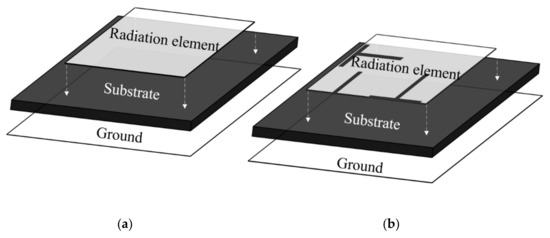
Figure 1.
Schematic configuration of (a) the unslotted antenna and (b) the slotted antenna structures.
Figure 2 shows the comparison of return losses between the above two types of antennas. The slotted antenna had the bandwidth of 8.16% with the return loss value lower than −10 dB in the frequency range from 2.38 to 2.58 GHz. In comparison with the unslotted antenna, the bandwidth had a 122% increase. It was clear that after slotting, these slots reduced the Q value of the antenna and expanded the bandwidth of the antenna. In adjustment of the slotted structure, the new peak gains occurred and the bandwidth was increased accordingly.
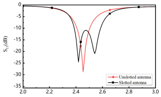
Figure 2.
Comparison of the simulated return losses for the antennas.
3.2. The Prototype of the Slotted Antenna
The size parameters of the designed textile slotted antenna were shown in Figure 3 and the detailed size was listed in Table 1. According to the size, the antenna was fabricated by the screen printing method. The antenna substrate was the aforementioned polyester felt and the conductive parts, including the radiation element and ground plane, were silver paste coating with the electrical conductivity of 5.5 × 10⁶ S/m. The coaxial feeding was applied for the antenna and the SMA connector was fixed throughout the thickness of the substrate.
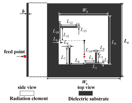
Figure 3.
The detailed size of the final slotted antenna.

Table 1.
Dimension parameters of the slotted antenna.
Figure 4 shows the slotted antenna prototype. It can be seen that the silver nanoparticles in the silver paste coating on the white polyester felt had a uniform and dense distribution and exhibited a light yellow color. As the silver paste coating was screen printed onto the polyester felt, to determine the adhesion of the silver paste coating with the polyester felt substrate, black colored adhesive tapes were used, which were stuck to the silver coating repeatedly; and each time, the dropped silver fiber residue was detected by the polarized light microscope (ECLIPES LV 100N POL). The smaller the amount of fiber residue, the better the adhesion between the silver coating and the substrate.
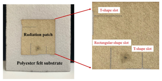
Figure 4.
Prototype of the slotted microstrip antenna.
Figure 5 shows the appearance of the tape surface after sticking. It is clear to see that when the sticking times were from 0 to 3, there was nearly no silver residue on the tape surface. When the sticking times reached 10 and 20, there were very few residue particles on the tape surface. The above observation shows that good adhesion between the silver coating and polyester felt was built after the fabrication of screen printing.
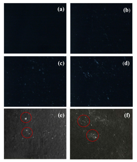
Figure 5.
The appearance of the tape surface: (a) no sticking, (b) 1-time sticking, (c) 2-time sticking, (d) 3-time sticking, (e) 10-time sticking, (f) 20-time sticking.
3.3. Design and Loading of the AMC on the Antenna
As our designed antenna would be used for the on-body application, the high gain and low back-lobe radiation were required. Herein, the AMC structure was designed and would be loaded onto the antenna. The AMC structure is a kind of EBG structure, which not only has the property of preventing the electromagnetic wave of a certain frequency band from propagating on its surface, but also can reflect the electromagnetic wave of vertical or oblique incidence in the same phase. The typical schematic picture is shown in Figure 6a. In this study, polyester felt was selected as the substrate of the AMC.
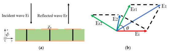
Figure 6.
The composed electromagnetic waves obtained from the incident wave and reflected wave: (a) the typical schematic picture of the principle of AMC, (b) the formation principle schematic picture of the composed electromagnetic waves.
As shown in Figure 6b, Ei is the incident wave; Er1 and Er2 are the reflected waves. E1 is the composed electromagnetic wave from Er1 and Ei; while E2 is from Er2 and Ei. When is in the range of −90° to +90°, the composed wave intensity from the incident wave and the reflected wave increases. When the frequency of the incident electromagnetic wave has the same value as the resonant angular frequency of the AMC structure, the surface impedance of the AMC is infinite. When the reflection phase band gap of the AMC structure is between −90° and +90°, its corresponding resonance angular frequency band is the reflection phase bandwidth [18].
When the AMC is loaded under the ground of the antenna, the backward radiation will be reflected, and the positive gain will be amplified due to the same phase reflection property of the AMC [19,20,21]. Therefore, it was particularly important to load the AMC structure to optimize the antenna performance. In this study, the AMC structure without a metal connecting column was used to facilitate fabrication and did not change the reflection phase characteristics of the AMC [22].
The size parameters of the AMC were analyzed as shown in Figure 7. In Figure 7a,b, H was the thickness of the AMC unit. The substrate and ground plane of the AMC were square shapes with size of Wg and Lg, and the conductive element was also square shaped with a size of Wp and Lp.
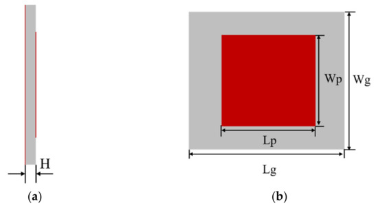
Figure 7.
The schematic configuration of the AMC unit: (a) the side view and (b) the top view.
To get the proper AMC unit size, a series of optimization work was done. As shown in Figure 8a,b, the reflection phase dependence of frequencies were investigated under different Lp and Lg size parameters, which finally showed that when Lp and Wp were 41 mm, and Lg and Wg were 43 mm, the anticipated results could be obtained. From Figure 8c, it was clear that when the reflection phase was in the range of −90° to +90°, the corresponding frequency was between 2.3 and 2.6 GHz.
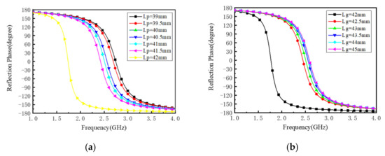
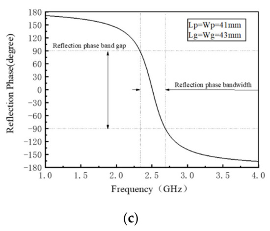
Figure 8.
Reflection phase curve of the AMC element: (a) Lp effect on the reflection phase, (b) Lg effect on the reflection phase, (c) the reflection phase of the final AMC unit size.
The whole size of the slotted microstrip antenna was 70 mm × 70 mm× 3 mm, and the overall size of square AMC structural unit was 43 mm × 43 mm × 3 mm. In order to ensure the performance of a square AMC was good and the whole size of the wearable antenna was relatively small, a 3 × 3 array AMC was selected to combine with the textile slotted antenna, and the designed and prototype figures are shown in Figure 9a,b.
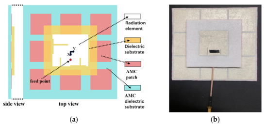
Figure 9.
Textile slotted microstrip antenna loaded with AMC: (a) designed and (b) prototype figure.
3.4. The Performance of Textile Slotted Microstrip Antenna
Figure 10 shows the measured return loss and radiation pattern of the antennas with and without AMC in free space. The return losses in Figure 10a had no significant differences between the two antennas, indicating in the free space environment the existence of the AMC would not nearly influence the impedance matching. In Figure 10b, the antenna loaded with the AMC had obvious small back lobes compared with the unloaded AMC antenna, whether for the E-plane or H-plane.
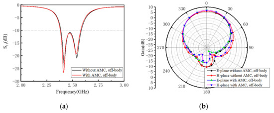
Figure 10.
The measured return loss (a) and radiation pattern (b) of textile slotted microstrip antenna with and without AMC at 2.45 GHz.
In the current on-body antenna performance study, the simulation method was used, as on-body testing is complicated. In this study, human tissue was simulated and the simulation model is given in Figure 11. The properties of the human tissue at 2.45 GHz are shown in Table 2 [23]. Figure 12 shows the on-body and off-body antenna return loss with and without the existence of the AMC. The on-body antenna without AMC had obviously different return loss behavior from the other three, showing that the human body, as a very efficient conductor, had great impact on the antenna return loss. While for the on-body antenna with AMC, the return loss curve had almost no significant difference, when compared with the off-body antenna return loss. In Figure 13, the radiation patterns for the E-plane and H-plane without AMC showed that the antenna without AMC had the protruding back lobe, which verified that the existence of an AMC could reduce the back gain and protect the human body from radiation invasion efficiently.
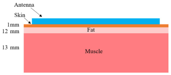
Figure 11.
The human tissue simulation model.
Table 2.
Properties of human tissue at 2.45 GHz.
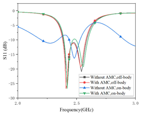
Figure 12.
The simulated return loss of the textile slotted microstrip antenna.
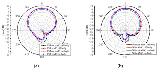
Figure 13.
The simulated radiation patterns of the textile slotted microstrip antenna at 2.45 GHz: (a) E-plane, (b) H-plane.
Figure 14 gives the comparison of SAR value distribution on human tissue, and it can be seen that the radiation elements of the AMC loaded antenna showed apparently less radiation compared with the unloaded AMC antenna. The highest SAR value from the antenna with AMC was 0.23 W/kg, which was much lower than the antenna without AMC with SAR value of 256 W/kg. As the requirement for the International Commission on Non-Ionizing Radiation Protection is below 2 W/kg, the antenna radiation is thought to be safe. Therefore, our designed antenna loaded with AMC meets the above requirement. In a future study, the on-body antenna performance would be explored to be tested to fully characterize the wearable textile antenna performance.
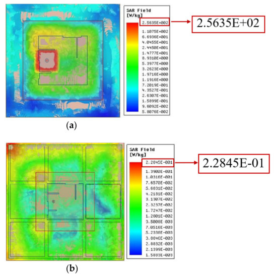
Figure 14.
The simulated distribution of SAR values on human tissue of textile slotted microstrip antenna: (a) without an AMC, (b) with an AMC.
4. Conclusions
In this study, a new type of full textile slotted antenna was designed and fabricated by the screen printing method. Polyester felt was selected as the dielectric substrate of textile antenna and its dielectric properties were determined by the model fitting method. The final size of the radiation element of the slotted textile antenna was decreased by 24.5% from that of the unslotted one and the bandwidth of the slotted antenna had a 122% increase. In the antenna fabrication process, to detect the adhesion of the silver ink with the polyester felt substrate, sticking tape was used. The tape surface was observed and the adhesion was verified to be good. As the designed antenna would be used for on-body application, the AMC structure was designed and loaded to our aforementioned antenna. The antenna performance results showed that the existence of the AMC had a positive effect on the reduction of body coupling and backward radiation. Compared with the unloaded AMC antenna, the SAR value decreased from 256 to 0.23 W/Kg, making the wide usage of on-body wearable antennas possible. To fully characterize the textile antenna, the real in situ on-body antenna property testing will be carried out in a future study, and if a more accurate response be obtained, the wearable antennas could be developed more efficiently.
Author Contributions
Conceptualization, L.Y.; methodology, E.L. and J.Y. (Jiangshan Yan); software, J.Y. (Jiangshan Yan), Y.R. and J.Y. (Jiahua Yang); validation, Z.S. (Zhiyong Shan), X.R. and Z.S. (Zhiyi Shen); formal analysis, L.Y.; investigation, E.L. and J.Y. (Jiangshan Yan), resources, E.L.; data curation, L.Y.; writing—original draft preparation, L.Y., E.L. and J.Y. (Jiangshan Yan); writing—review and editing, Z.S. (Zhiyong Shan); visualization, E.L.; supervision, L.Y. and Z.S. (Zhiyong Shan). All authors have read and agreed to the published version of the manuscript.
Funding
This research was funded by the National Natural Science Foundation of China, grant number 50803010.
Conflicts of Interest
The authors declare no conflict of interest.
References
- Manna, S.; Bose, T.; Bera, R. Wearable antennas for medical application: A review. In Advances in Electronics, Communication and Computing; Springer: Berlin, Germany, 2018; pp. 115–130. [Google Scholar]
- Yan, S.; Soh, P.J.; Vandenbosch, G.A.E. Wearable ultrawideband technology-a review of ultrawideband antennas. Propagation channels, and applications in wireless body area networks. IEEE Access 2018, 6, 42177–42185. [Google Scholar] [CrossRef]
- Abbas, S.M.; Esselle, K.P.; Matekovits, L.; Rizwan, M.; Ukkonen, L. On-body Antennas: Design considerations and challenges. In Proceedings of the 2016 Ursi International Symposium on Electromagnetic Theory, Espoo, Finland, 14–18 August 2016; IEEE: New York, NY, USA, 2016; pp. 109–110. [Google Scholar]
- Guo, X.; Liao, W.; Zhang, Q.; Chen, Y. A dual-band embedded inverted t-slot circular microstrip patch antenna. In Proceedings of the 2016 IEEE 5th Asia-Pacific Conference on Antennas and Propagation, Kaohsiung, China, 26–29 July 2016; pp. 151–152. [Google Scholar]
- Dwivedi, A.D.; Garg, M.K.; Katariya, P.S.; Gautam, D.; Singh, S. C band, X band and Ku band corner arc microstrip patch antenna with t-slot on partial ground plane. In Proceedings of the 2017 International Conference on Innovations in Control, Communication and Information Systems, Noida, India, 12–13 August 2017; pp. 41–44. [Google Scholar]
- Murugan, S.; Rohini, B.; Muthumari, P.; Priya, M.P. Multi-Frequency t-slot loaded elliptical patch antenna for wireless applications. Appl. Comput. Electromagn. Soc. J. 2018, 33, 247–250. [Google Scholar]
- Xie, Z.; Avila, R.; Huang, Y.; Rogers, J.A. Flexible and stretchable antennas for biointegrated electronics. Adv. Mater. 2019, 32, e1902767. [Google Scholar] [CrossRef] [PubMed]
- Stoppa, M.; Chiolerio, A. Wearable electronics and smart textiles: A critical review. IEEE Access 2014, 14, 11957–11992. [Google Scholar] [CrossRef] [PubMed]
- Kavitha, A.; Swaminathan, J.N. Design of flexible textile antenna using FR4, jeans cotton and teflon substrates. Microsyst. Technol. Micro Nanosyst. Inf. Storage Process. Syst. 2019, 25, 1311–1320. [Google Scholar] [CrossRef]
- Nesar, M.S.B.; Chakma, N.; Muktadir, M.A.; Biswas, A. Design of a miniaturized slotted t-shaped microstrip patch antenna to detect and localize brain tumor. In Proceedings of the 2018 International Conference on Innovations in Science, Engineering and Technology (ICISET), Chittagong, Bangladesh, 27–28 October 2018; pp. 157–162. [Google Scholar]
- Zhu, S.; Langley, R. Dual-Band wearable textile antenna on an EBG substrate. IEEE Trans. Antennas Propag. 2009, 57, 926–935. [Google Scholar] [CrossRef]
- Raad, H.R.; Abbosh, A.I.; Al-Rizzo, H.M.; Rucker, D.G. Flexible and compact AMC based antenna for telemedicine applications. IEEE Trans. Antennas Propag. 2013, 61, 524–531. [Google Scholar] [CrossRef]
- Soh, P.J.; Giman, F.N.; Jamlos, M.F.; Lago, H.; Al-Hadi, A.A. A c-slotted dual band textile antenna for WBAN applications. In Proceedings of the 2016 Ursi Asia-Pacific Radio Science Conference, Seoul, Korea, 21–25 August 2016; pp. 1621–1624. [Google Scholar]
- Ashyap, A.Y.I.; Abidin, Z.Z.; Dahlan, S.H.; Majid, H.A.; Shah, S.M.; Kamarudin, M.R.; Alomainy, A. Compact and low-profile textile EBG-based antenna for wearable medical applications. IEEE Antennas Wirel. Propag. Lett. 2017, 16, 2253–2550. [Google Scholar] [CrossRef]
- Paracha, K.N.; Rahim, S.K.A.; Soh, P.J.; Khalily, M. Wearable antennas: A review of material,s, structures, and innovative features for autonomous communication and sensing. IEEE Access 2019, 7, 56694–56712. [Google Scholar] [CrossRef]
- Mohamadzade, B.; Hashmi, R.M.; Simorangkir, R.B.V.B.; Gharaei, R.; Rehman, S.U.; Abbasi, Q.H. Recent advances in fabrication methods for flexible antennas in wearable devices: State of the art. Sensors 2019, 19, 2312. [Google Scholar] [CrossRef] [PubMed]
- Shi, J.; Liu, S.; Zhang, L.; Yang, B.; Shu, L.; Yang, Y.; Ren, M.; Wang, Y.; Chen, J.; Chen, W.; et al. Smart textile-integrated microelectronic systems for wearable applications. Adv. Mater. 2020, 32, 1901958. [Google Scholar] [CrossRef] [PubMed]
- Sievenpiper, D.; Zhang, L. High-impedance electromagnetic surfaces with a forbidden frequency band. IEEE Trans. Microw. Theory Tech. 1999, 47, 2059–2074. [Google Scholar] [CrossRef]
- Alemaryeen, A.; Noghanian, S. On-Body low-profile textile antenna with artificial magnetic conductor. IEEE Trans. Antennas Propag. 2019, 67, 3649–3656. [Google Scholar] [CrossRef]
- Paracha, K.N.; Rahim, S.K.A.; Soh, P.J.; Chatha, H.T.; Misran, M.H.; Lokman, A.H. A dual band stub-loaded AMC design for the gain enhancement of a planar monopole antenna. Microw. Opt. Technol. Lett. 2018, 60, 2108–2112. [Google Scholar] [CrossRef]
- Alemaryeen, A.; Noghanian, S. Crumpling effects and specific absorption rates of flexible AMC integrated antennas. IET Microw. Antennas Propag. 2018, 12, 627–635. [Google Scholar] [CrossRef]
- Yang, F.R.; Ma, K.P.; Qian, Y.X.; Itoh, T. A uniplanar compact photonic-bandgap (UC-PBG) structure and its applications for microwave circuits. IEEE Trans. Microw. Theory Tech. 1999, 47, 1509–1514. [Google Scholar] [CrossRef]
- Abbas, S.M.; Esselle, K.P.; Ranga, Y.; Antennas, I.; Propagat, S. A printed antenna with a ground plane and electromagnetically coupled feed for 2.45 GHz body area networks. In Proceedings of the 2013 IEEE Antennas and Propagation Society International Symposium, Orlando, FL, USA, 7–13 July 2013; pp. 2143–2144. [Google Scholar]
Publisher’s Note: MDPI stays neutral with regard to jurisdictional claims in published maps and institutional affiliations. |
© 2021 by the authors. Licensee MDPI, Basel, Switzerland. This article is an open access article distributed under the terms and conditions of the Creative Commons Attribution (CC BY) license (https://creativecommons.org/licenses/by/4.0/).