Article

Coordinate Transformations-Based Antenna Elements Embedded in a Metamaterial Shell with Scanning Capabilities

1
Department of Electrical and Computer Engineering, North Dakota State University, Fargo, ND 58105, USA
2
Air Force Research Laboratory, Munitions Directorate, Eglin Air Force Base, FL 32542, USA
*
Authors to whom correspondence should be addressed.
Electronics 2021, 10(9), 1081; https://doi.org/10.3390/electronics10091081
Submission received: 9 April 2021 / Revised: 29 April 2021 / Accepted: 1 May 2021 / Published: 3 May 2021
(This article belongs to the Special Issue Metamaterials and Metasurfaces)

Abstract

:
In this work transformation electromagnetics/optics (TE/TO) were employed to realize a non-homogeneous, anisotropic material-embedded beam-steerer using both a single antenna element and an antenna array without phase control circuitry. Initially, through theory and validation with numerical simulations it is shown that beam-steering can be achieved in an arbitrary direction by enclosing a single antenna element within the transformation media. Then, this was followed by an array with fixed voltages and equal phases enclosed by transformation media. This enclosed array was scanned, and the proposed theory was validated through numerical simulations. Furthermore, through full-wave simulations it was shown that a horizontal dipole antenna embedded in a metamaterial can be designed such that the horizontal dipole performs identically to a vertical dipole in free-space. Similarly, it was also shown that a material-embedded horizontal dipole array can perform as a vertical dipole array in free-space, all without the need of a phase shifter network. These methods have applications in scanning for wireless communications, radar, beam-forming, and steering.

1. Introduction

The concepts of transformation optics (TO) [1,2] have been used to control the propagation characteristics of electromagnetic (EM) fields in interesting and useful ways by using regions of non-homogeneous, anisotropic materials. Based on the form-invariant nature of Maxwell’s equations [3], the TO technique leads to implementation of unconventional electromagnetic devices using novel wave–matter interactions computed with coordinate transformations. One salient example is the cloak [4]. This success led to the development of many other unique EM devices [5,6,7,8,9,10,11,12,13,14,15] that exhibit unconventional and unusual propagation characteristics.
Phased array antennas have garnered significant interest in wireless communications applications due to their capability to change the shape and direction of the radiation pattern without physically moving the antennas. This technique is often referred to as beam-steering and can be accomplished by rotating the antenna elements or changing the relative phases of the radio-frequency (RF) signals driving the elements. Beam-steering of a phased array antenna is often a challenging task because it involves synthesis of multiple antenna elements and integration of control circuits, including solid-state phase shifters [16] and beam-forming networks [17], to control or guide the beam in a desired direction, as shown in Figure 1a. Recently, researchers showed that the TO technique could be useful to control the beam in a specific direction using coordinate transformations-based non-homogeneous material regions. Rahm et al. [7] showed how to design a beam shifter using TO.
Utilizing a similar idea, researchers in [12,13] proposed a set of beam-shifters to avoid obstacles in the beam path. In [18], researchers experimentally showed a TO-based lens for beam control at microwave frequencies. This pioneering research paved the way for beam-steering of antennas using the TO technique. The concepts of TO were later expanded to design unique antennas [19,20] and phased array antennas for different conformal applications [21,22,23]. In [24], it was shown that the techniques of TO can be utilized to manipulate EM fields and rotate them in a specified direction.
This approach can thus be used to control radiation characteristics of an antenna element (as shown in Figure 1b) or an antenna array in free-space and to rotate it in a desired direction, hence realizing a beam-steerer using TO-based media. This specific TO approach results in material properties that require active tuning to achieve beam-steering, but significant advancements and attention given to reconfigurable material properties, specifically in tunable constitutive parameters (permittivity and permeability), could in the future allow for practical implementation of novel beam-steering techniques [25,26,27,28]. Misra et al. [25] demonstrated electrically tunable permittivity in BaTiO3 under DC bias conditions. In [26], researchers showed the influence of DC bias and temperature on the dielectric permittivity to achieve switchable dielectric permittivity in a semifluorinated azobenzene. Significant research has been done to control the permeability of materials. In [27] researchers proposed microfluidic split-ring resonators inside a flexible elastomeric material to achieve reconfigurable effective permeability. Agarwal et al. [28] demonstrated the preparation of adaptive hybrid capsules with microgel/SiO2 composite walls with tunable shell permeability.
Therefore, the objective of this work was to present a design and application of a TO-based cylindrical rotator for beam-steering, where a single dipole antenna element (as shown in Figure 2a) and an antenna array (as shown in Figure 2b) are enclosed by a TO-based non-homogeneous, anisotropic material shell designed using the transformation introduced in [24] (shown by the dotted ring in Figure 2). Through numerical simulations, beam- steering of the TO-based single element and the antenna array was demonstrated without using any phase control circuitry.
Then, the same TO-based cylindrical beam-rotator was applied to a vertical dipole antenna in free-space to design a horizontal dipole antenna. It was shown that the horizontal dipole element embedded in a metamaterial radiated in a similar manner as that of the vertical dipole element in free-space. Similarly, the TO-based cylindrical beam-rotator was also applied to a co-linear vertical array in free-space to design a horizontal co-linear array, where through numerical simulations it was shown that the material-embedded horizontal array radiates in the same manner as the vertical array in free-space. Finite element method-based full-wave simulations via COMSOL Multiphysics ® were used to numerically analyze and demonstrate the performance of the proposed TO-based beam-scanning technique. It should be noted that the theory that was validated by COMSOL Multiphysics is similar to the approaches taken by previous works and reported in [19,20,21,22,23,24].

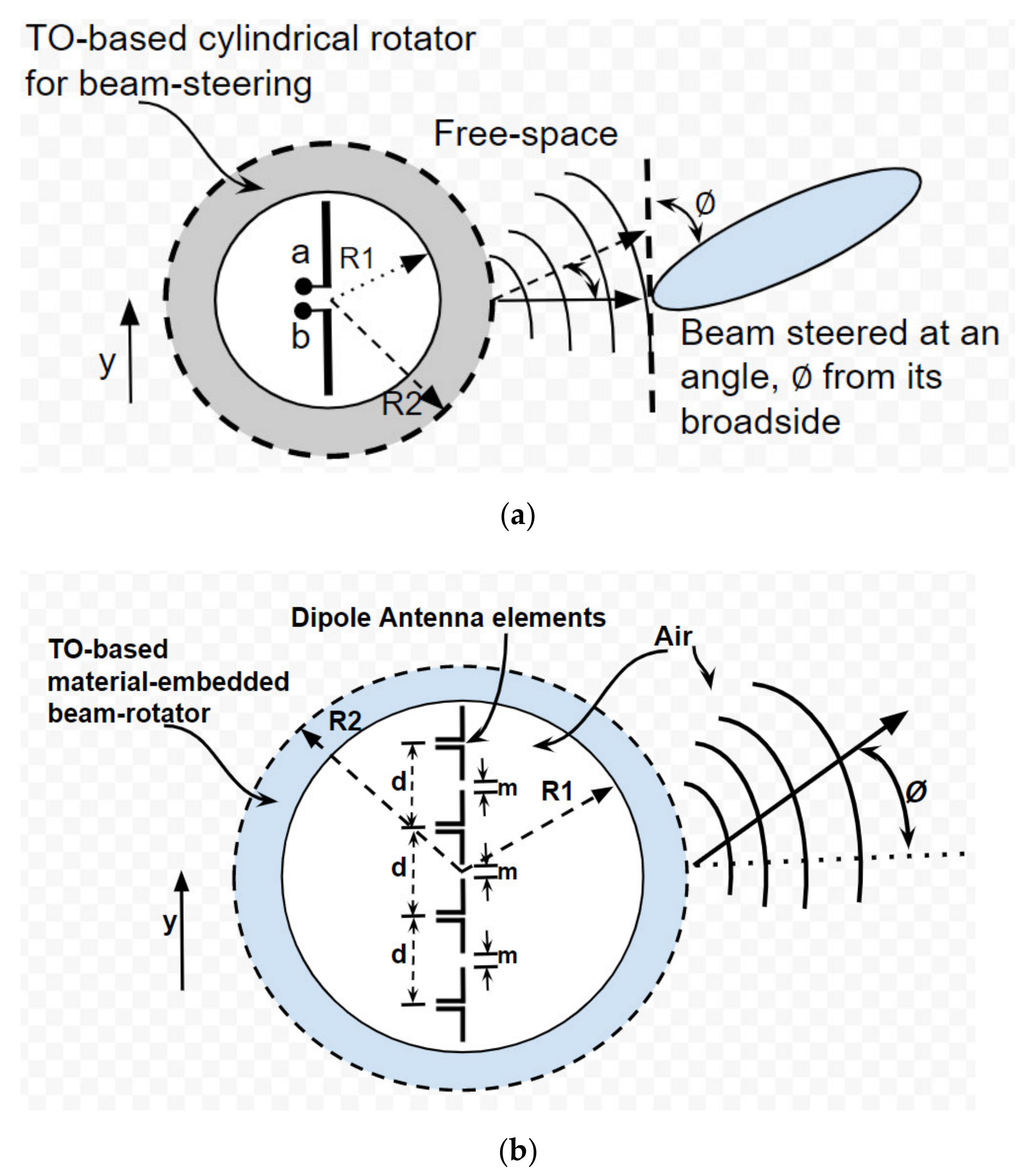
2. Proposed TO-Based Single Element Cylindrical Beam-Steerer

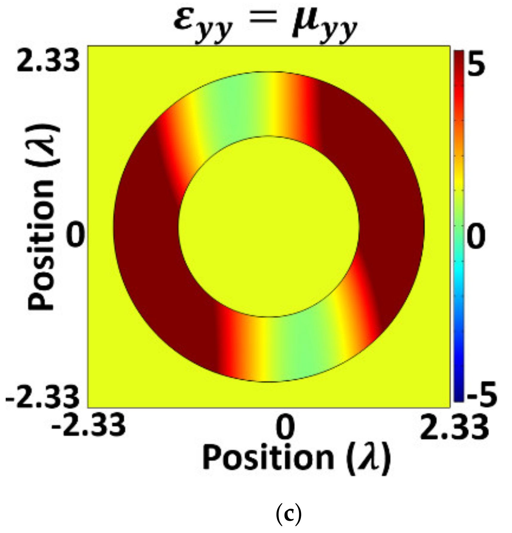
2.1. Theoretical Model

Consider the dipole element positioned in free-space along the y-axis represented in Figure 1b. The dipole is of λ length, where λ is the free-space wavelength at which the dipole antenna is designed to operate. The current distribution of the dipole in Figure 1b along x = 0 was chosen to be [19,20]:
j ¯ = 0 1 σ π . 0 e y 2 σ
where σ is much smaller than the length of the dipole. The current distribution model is a way of handling sheet current as the limit of a volumetric current density, which was suggested in [19,20]. The sigma parameter is set to be infinitesimally small relative to the length of the dipole and the limit σ 0 can be taken to approximate the current distribution on a thin wire at x = 0 [19,20]. The intent is to introduce a TO- based material shell (again as illustrated as the grey ring in Figure 2a) to control the radiation characteristics of the dipole element to steer its beam to a desired direction. Starting with the basic transformation media approach, the associated permittivity and permeability tensors of transformation media are given by [29]:
ε = μ = A ε A T det A
where A = x , y , z / x ,   y ,   z is the Jacobian matrix and A T is the transpose of the Jacobian. The mapping between the original ( r ,   θ ,   z ) and the transformed ( r , θ , z ) cylindrical coordinate systems are [24]:
  r = r ,
  θ = θ + β ,   r < R 1 θ + β R 2 r R 2 R 1 ,   R 1 r < R 2 θ ,   r R 2  
z = z ,
where β is the angle of rotation in the region between radii R 1 and R 2 in Figure 2. By controlling the rotation angle β , it is possible to control the radiation characteristics and by extension the amount of beam-steering in a desired direction using a single antenna element and the array without phase control circuitry and multiple antenna elements, as shown in Figure 2. The transformation Equation (2) yields the permittivity and permeability tensors of the material between r = R 1 and r = R 2 as [24]:
ε = μ = 1 + 2 d f + d 2 s i n 2 θ d 2 f d g 0 d 2 f d g 1 2 d f + d 2 c o s 2 θ 0 0 0 1 ,
where d = β r R 2 R 1 , f = c o s θ s i n θ ,   g = c o s 2 θ s i n 2 θ , and ε = μ = I in other regions in Figure 2.
Equation (6) results in anisotropic and inhomogeneous permittivity and permeability tensors for the spherical shell. Note that the results lead to a perfect impedance matching with no reflection at the boundaries of the material region and free-space, which is shown in Figure 3. Such an anisotropic and inhomogeneous transformation medium can be realized by discrete metamaterials and structures such as periodic split ring resonators (SRRs) [30]. The theoretical material parameters in Equation (6) were validated using full-wave simulations in the finite element solver COMSOL Multiphysics ®, as shown in Figure 3. An incident TE plane wave of 10 GHz frequency was used from left to right along the x-direction. The inner radius R 1 = 1.1 λ , and the outer radius   R 2 = 2 λ . The radii R 1 and R 2 of the metamaterial coating were chosen by closely following the similar works reported in [24] and [31]. As the dipole element was full-wave ( L = λ ), it was necessary to choose an inner radius R 1 of the metamaterial coating that was bigger than the length of the dipole, so that it follows the transformation rule from Equation (4). The metamaterial coating is located in the radiative near field region, as   0.62 D 3 λ < metamaterial   coating < 2 D 2 λ , where D = L = maximum linear dimension of the antenna, and λ = wavelength of the EM wave.
The material parameters were calculated using Equation (6) for different angles of rotation ( β ). Numerical simulations were also completed to see the spatial variation of the constitutive material parameters, as shown in Figure 4, and it was observed that the material parameters were well within the range of material properties (permittivity and permeability) mentioned in [25,26,27]. The rotation angle β was chosen to be 45° for the simulations.
Next, a full-wave ( λ ) dipole antenna element was placed in the region   r < R 1 and the material parameters from Equation (6) were used to design the cylindrical beam-steerer in the region   R 1 r < R 2 to control the radiation characteristics of the dipole element in a desired direction, as shown in Figure 2a. The beam-steering angle   ϕ of the dipole antenna element is controlled by the rotation angle β . Equations (4) and (6) show that it is possible to rotate the EM fields in an arbitrary direction, which makes the beam-rotator capable of steering the beam.

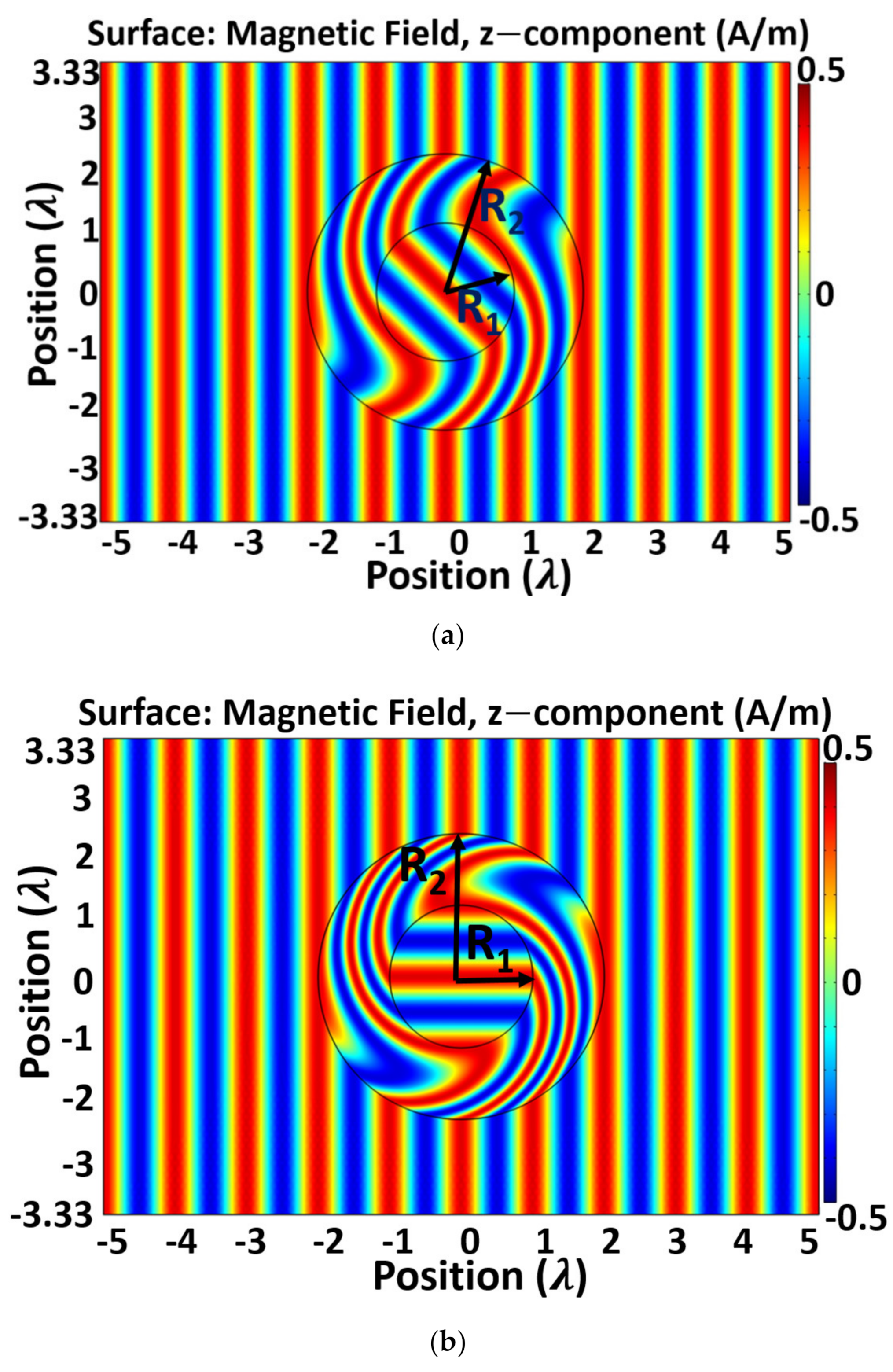
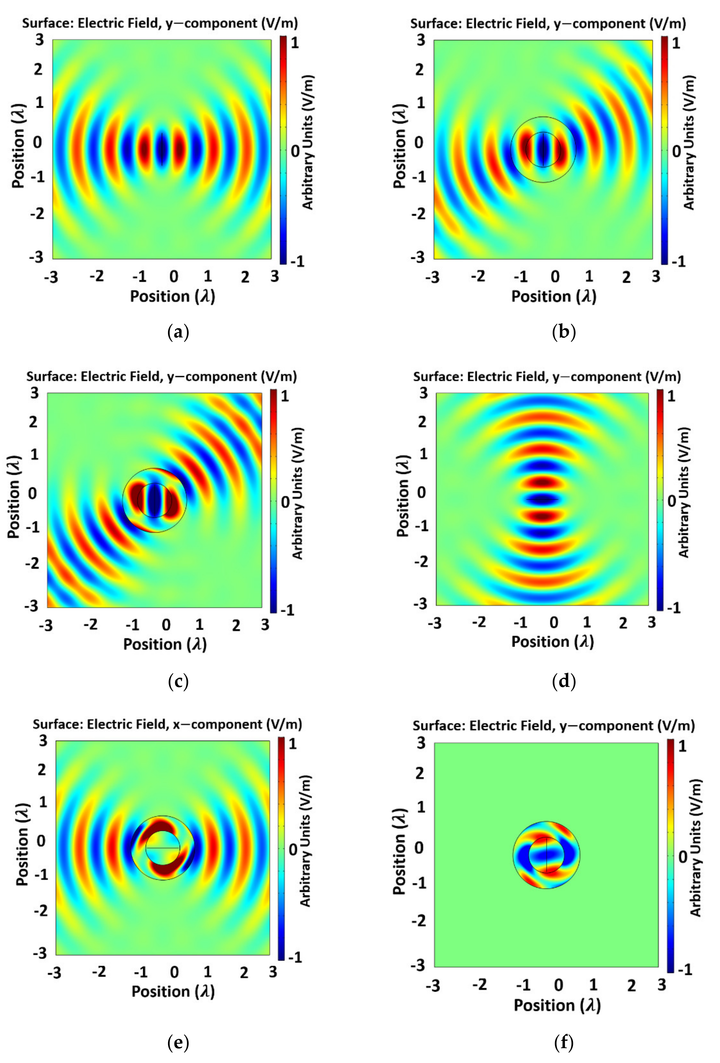
2.2. Full-Wave Simulation Results

The objective of this research was to exploit the concepts of transformation electromagnetics/optics (TE/TO) for realizing a beam-steering technique using a rotation mapping introduced in [24]. For simplicity and ease of coordinate transformation, here, no transformation was considered along the z-direction. As a result, a 2D transformation media was chosen, which resulted in material parameters in Equation (6). An experimental realization of the rotation coating requires building blocks that have anisotropic dielectric functions, and a similar theory of this kind of rotation mapping could be extended to 3D. In that case, we will have permittivity and permeability tensors in Equation (6) due to variations along the z-direction.
The performance of the proposed single element TO-based beam-steerer, as shown in Figure 2a, was demonstrated through numerical solutions in the finite-element simulation software COMSOL Multi-physics ®. Figure 5 presents the y-component of the electric field of the proposed single element beam-rotator verifying the transformed media from (6). Figure 5a shows the simulation results from a full-wave ( L = λ ) dipole antenna in free-space along the y-direction (Figure 1b). This will be called the “vertical dipole”. A frequency of 10 GHz was chosen. Now, to control the radiation characteristics of the dipole element in a desired direction, the transformation media from (6) was used as the beam-steerer around the dipole and the rotation angle β in (4) was controlled to steer the beam of the dipole antenna element in the desired direction. A rotation angle β = 22.5° was chosen to rotate the fields pattern of the vertical dipole at an angle of 22.5°, as a result, the beam was steered at an angle ϕ = 22.5°, as shown in Figure 5b. Similarly, rotation angle β = 45° was chosen to steer the beam of the vertical dipole to an angle ϕ = 45° (Figure 5c). Figure 5d shows electric field radiation of a full-wave ( L = λ ) dipole antenna in free-space along the x-direction. This is denoted as the “horizontal dipole” antenna. The current distribution from (1) was re-defined for the horizontal dipole as the location of the dipole changed to y = 0 from x = 0. Now, the TO-based beam-rotator was used and a rotation angle β = 90° was chosen to transform the horizontal dipole into the vertical dipole, as shown in Figure 5e. The fields from the vertical dipole in Figure 5a and the transformed horizontal dipole antenna in Figure 5e outside the material shell are the same. Figure 5f verifies that the difference between the two fields is negligible and there is almost no field distribution outside the transformation media.
Furthermore, the far-field radiation patterns of the TO-based beam-rotator using a single antenna element were simulated and are illustrated in Figure 6. As shown in Figure 6a, the transformation media from (6) was used to rotate the beam of the vertical dipole in free-space to angles of ϕ = 22.5° and ϕ = 45° by setting the rotation angles β = 22.5 ° and β = 45 ° in transformation media from (6), respectively. Moreover, Figure 6b shows that the radiation pattern of the vertical dipole in free-space is similar to the radiation pattern of the horizontal dipole, when the horizontal dipole is enclosed by the transformation media and is rotated by   β = 90 ° , but is different if the horizontal dipole is not enclosed by the transformed medium and is not rotated by an angle   β = 90 ° .
Moreover, considering that losses exist in practical materials, numerical simulations were performed incorporating different values of loss tangents ( tan δ ), as shown in Figure 7. Loss was incorporated in the simulations by replacing ε x x with ε x x j ε x x tan   δ [22,23]. Other tensor parameters were also modified similarly. A rotation angle   β = 22.5 ° was chosen to steer the beam at 22.5°. Figure 7 shows that while the antenna’s radiated field strength degrades with the increase of loss factor, its overall steering capability remains unchanged. With the loss tangent reduced to only 0.1, the effect of loss is almost unnoticeable. No significant differences were observed in the range tan δ 0.01 .

3. Proposed Antenna Array Enclosed by TO-Based Cylindrical Beam-Steerer

The same TO technique from Section 2.1 can be utilized to realize a cylindrical beam-rotator enclosing an antenna array with the TO-based non-homogeneous, anisotropic media. Next, consider the N-element co-linear dipole array along the y-axis represented in Figure 2b. Each of the elements in the array are equally spaced with the edge-to-edge distance between the elements of m = λ / 15 , where   λ is the free-space wavelength at which the phased array is designed to operate. A two-dimensional (2D) space is considered to illustrate the proposed array. The current distribution of each of the dipole elements in the array is approximated as the current distribution of a thin wire along x = 0 and is defined by Equation (1). In this case, an array of four elements is chosen to validate the proposed beam scanning method. Each of the dipoles in the array is of λ / 2 length spanning over a distance of 2.2 λ . There was no phase difference considered between the adjacent dipole elements. Here, a TO-based material shell enclosing the dipole array to control the radiation characteristics of the array and steer its beam to a desired direction as shown in Figure 2b is introduced.
Next, the four-element dipole antenna array was placed in the region   r < R 1 and the material parameters from Equation (6) were used to design the cylindrical beam-steerer in the region   R 1 r < R 2 enclosing the array to control the radiation characteristics of the antenna array in a desired direction, as shown in Figure 2b. The beam-scanning angle   s of the dipole antenna array will be controlled by the rotation angle β from (6). From Equations (4) and (6), it is shown that it is possible to rotate the EM fields in an arbitrary direction, which makes the beam-rotator capable of steering the dipole antenna array pattern in a desired direction, thus enabling antenna array scanning.

Full-Wave Simulations Results

The performance of the proposed phased array antenna enclosed by TO-based material-embedded cylindrical beam-steerer, as shown in Figure 2b, was demonstrated through numerical solutions in the commercially available finite-element simulation software COMSOL Multiphysics ®. Figure 8 presents the y-component of the electric field of the proposed beam-rotator for scanning of the phased array antenna verifying the transformed media from (6). Figure 8a demonstrates the simulation results from the dipole antenna array in free-space along the y-direction (as shown in Figure 2b). For reference, it will be called the “vertical array”. A frequency of 10 GHz was chosen. To control the radiation characteristics of the dipole antenna array in a desired direction, the transformation media from (6) was used as the beam-steerer around the array and the rotation angle β in (4) was controlled to steer the beam of the dipole antenna array in the desired direction. A rotation angle β = 22.5° was chosen to rotate the field patterns of the “vertical array” at an angle of 22.5°, as a result, a beam-scanning of the “vertical dipole array” occurred at an angle s = 22.5°, as shown in Figure 8b. Similarly, rotation angle β = 45° was chosen to scan the “vertical dipole array” beam to an angle s = 45° (as demonstrated in Figure 8c).
Figure 8d presents the electric field radiation of a dipole antenna array in free-space along the x-direction. For reference, it is denoted as the “horizontal array”. The current distribution from (1) was adjusted for each of the elements of the “horizontal array” as the location of each dipole element changed to y = 0 from   x = 0 . Now, the “horizontal array” was enclosed by the proposed TO-based beam-rotator and a rotation angle β = 90° was chosen to transform the “horizontal dipole array” into the “vertical dipole array”, as shown in Figure 8e. The fields from the “vertical dipole array” in Figure 8a and the transformed “horizontal dipole array” in Figure 8e outside the material shell are the same. This is emphasized in Figure 8f, which shows almost no field distribution outside the transformation media when the difference between the two fields is taken, validating the results further.
Moreover, the far-field patterns of the proposed array enclosed by the TO-based material-embedded cylindrical beam-rotator were simulated and are illustrated in Figure 9. As shown in Figure 9a, the transformation media from (6) was used to rotate the beam of the “vertical array” in free-space to angles s = 22.5° and s = 45° by setting the rotation angles β = 22.5 ° and β = 45 ° in transformation media from (6), respectively. Moreover, Figure 9b shows that the radiation pattern of the “vertical array” in free-space is similar to the radiation pattern of the “horizontal array”, when the “horizontal array” is enclosed by the transformation media and is rotated by   β = 90 ° , but is different if the “horizontal array” is not enclosed by the transformed medium and is not rotated by an angle   β = 90 ° .
Furthermore, since practical metamaterial designs have losses, finite-element full-wave simulations were performed adding different values of loss tangent ( tan δ ). For a scan angle s   = 90°, the normalized radiation patterns of the TO-based “horizontal array” for different values of loss tangent ( tan δ ) are compared in Figure 10. Loss was incorporated in the simulations by replacing ε x x with ε x x j ε x x t a n   δ [22,23]. Similar modifications were made in other tensor material parameters. As loss is increased, the antenna’s radiated field strength degrades, but its overall steering capability remains unchanged, which is shown in Figure 10. With the loss tangent reduced to only 0.1, the effect of loss is almost insignificant. No noticeable differences were observed in the range tan δ 0.01 . Dispersion exists in all materials and systems, natural or manmade. There are many ways to implement the needed material properties given the frequency regime, application, environmental considerations, etc. Dispersion along with other fundamental properties such a loss, noise, etc. must always be taken into consideration to meet a specific application system’s requirements. Several research works [32,33,34] have been performed to explore and analyze the limitations of specific implementations of TO devices due to dispersive materials. To this end, we proposed a TO-based beam-steering technique that results in anisotropic, non-homogeneous material parameters. Keeping the practical implementation of metamaterials and its dispersive nature in mind, numerical simulations are presented in Figure 7 and Figure 10 by incorporating losses to see how the losses in the material parameters in Equation (6) affect the performances of the proposed beam-rotator. It is anticipated that the material parameters from Equation (6) will demonstrate a dispersive nature when practically implemented.

4. Conclusions

In conclusion, it has been shown how transformation optics can be utilized to steer a beam in an arbitrary direction from a single antenna element and an antenna array without using phase control circuitry and beam-forming networks. The proposed beam-steerer is a TO-based non-homogeneous, anisotropic material shell theoretically computed using coordinate transformations. The transformed parameters are derived, and through full-wave simulations, the beam-steering performances of the TO-based beam-steerer are demonstrated. Additionally, the TO-based beam-rotator is applied to the vertical dipole antenna in free-space to design a horizontal dipole antenna, and through numerical simulations it is shown that the material-embedded horizontal dipole element radiates as a vertical dipole element in free-space, verifying the design. Similarly, the TO-based beam-rotator is applied to a vertical dipole array to design a TO-based material-embedded horizontal dipole array, which behaves like a vertical dipole array in free-space. While we have presented numerical verification, in practice, this TO approach requires actively tuned material parameters. To this end, significant advancements have been made to realize actively tunable constitutive material parameters, which could enable practical implementation of this TO-based beam-steering technique.

Author Contributions

Conceptualization, D.M.; methodology, D.M.; software, D.M.; validation, D.M., S.D. and J.W.A.; formal analysis, D.M.; investigation, D.M., B.D.B., S.D. and J.W.A.; resources, B.D.B.; writing—original draft preparation, D.M.; writing—review and editing, D.M., S.D., J.W.A., M.S.A. and B.D.B.; supervision, B.D.B., M.S.A., and J.W.A.; project administration, B.D.B., M.S.A. and J.W.A.; funding acquisition, B.D.B., M.S.A. and J.W.A. All authors have read and agreed to the published version of the manuscript.

Funding

This research was funded by US Air Force Research Laboratory Munitions Directorate under Grant DSC6511-01.

Data Availability Statement

Data is available upon reasonable request from the corresponding authors.

Conflicts of Interest

The authors declare no conflict of interest.

References

  1. Pendry, J.B.; Schurig, D.; Smith, D.R. Controlling Electromagnetic Fields. Science 2006, 312, 1780–1782. [Google Scholar] [CrossRef] [Green Version]
  2. Leonhardt, U. Optical Conformal Mapping. Science 2006, 312, 1777–1780. [Google Scholar] [CrossRef]
  3. Post, E.J. Formal Structure of Electromagnetics, 1st ed.; Dover Publications, Inc.: New York, NY, USA, 1962. [Google Scholar]
  4. Schurig, D.; Mock, J.J.; Justice, B.J.; Cummer, S.A.; Pendry, J.B.; Starr, A.F.; Smith, D.R. Metamaterial electromagnetic cloak at microwave frequencies. Science 2006, 314, 977–980. [Google Scholar] [CrossRef] [Green Version]
  5. Chen, H.; Luo, X.; Ma, H.; Chan, C.T. The anti-cloak. Opt. Express 2008, 16, 14603–14608. [Google Scholar] [CrossRef]
  6. Yang, T.; Chen, H.; Luo, X.; Ma, H. Superscatterer: Enhancement of scattering with complementary media. Opt. Express 2008, 16, 18545–18550. [Google Scholar] [CrossRef] [PubMed] [Green Version]
  7. Rahm, M.; Cummer, S.A.; Schurig, D.; Pendry, J.B.; Smith, D.R. Optical design of reflectionless complex media by finite embedded coordinate transformations. Phys. Rev. Lett. 2008, 100, 063903. [Google Scholar] [CrossRef] [Green Version]
  8. Yi, J.; Tichit, P.; Burokur, S.N.; de Lustrac, A. Illusion optics: Optically transforming the nature and the location of electromagnetic emissions. J. Appl. Phys. 2015, 117, 084903. [Google Scholar] [CrossRef]
  9. Tichit, P.; Burokur, S.N.; Lustrac, A.D. Ultradirective antenna via transformation optics. J. Appl. Phys. 2009, 105, 104912. [Google Scholar] [CrossRef] [Green Version]
  10. Tichit, P.; Burokur, S.N.; Lustrac, A.D. Transformation media producing quasi-perfect isotropic emission. Opt. Express 2011, 19, 20551–20556. [Google Scholar] [CrossRef] [PubMed]
  11. Kwon, D.H.; Werner, D.H. Transformation optical designs for wave collimators, flat lenses and right-angle bends. New J. Phys. 2008, 10, 115023. [Google Scholar] [CrossRef]
  12. Wang, M.Y.; Zhang, J.J.; Chen, H.; Luo, Y.; Xi, S.; Ran, L.-X.; Kong, J. Design and Application of a Beam Shifter by Transformation Media. Prog. Electromagn. Res. 2008, 83, 147–155. [Google Scholar] [CrossRef] [Green Version]
  13. Mitra, D.; Cleveland, J.; Lewis, J.; Braaten, B.D.; Allen, J.; Allen, M. On the use of Multiple Beam-Shifters Developed using Transformation Electromagnetics to Control Propagation Characteristics. In Proceedings of the IEEE Research and Applications of Photonics in Defense Conference (RAPID), Miramar Beach, FL, USA, 10–12 August 2020; pp. 1–2. [Google Scholar]
  14. Rahm, M.; Roberts, D.A.; Pendry, J.B.; Smith, D.R. Transformation-optical design of adaptive beam bends and beam expanders. Opt. Express 2008, 16, 11555–11567. [Google Scholar] [CrossRef] [PubMed]
  15. Tichit, P.; Burokur, S.N.; Yi, J.; de Lustrac, A. Transformation Electromagnetics for Antennas with an Illusion on the Radiation Pattern. IEEE Antennas Wirel. Propag. Lett. 2014, 13, 1796–1799. [Google Scholar] [CrossRef]
  16. Mitra, D.; Roy, P.; Dawn, D. A variable gain CMOS phase shifter for phased array antenna applications. Microw. Opt. Technol. Lett. 2016, 59, 324–328. [Google Scholar] [CrossRef]
  17. Sanford, J.R. Design of a Miniature Reactive Beam Forming Network. In Proceedings of the 2019 IEEE International Symposium on Antennas and Propagation and USNC-URSI Radio Science Meeting, Atlanta, GA, USA, 7–12 July 2019; pp. 1357–1358. [Google Scholar]
  18. Yi, J.; Burokur, S.N.; Lustrac, A.D. Experimental validation of a transformation optics based lens for beam steering. Appl. Phys. Lett. 2015, 107, 154101. [Google Scholar] [CrossRef]
  19. Kundtz, N.; Roberts, D.A.; Allen, J.; Cummer, S.; Smith, D.R. Optical source transformations. Opt. Express 2008, 16, 21215–21222. [Google Scholar] [CrossRef] [PubMed] [Green Version]
  20. Allen, J.; Kundtz, N.; Roberts, D.A.; Cummer, S.A.; Smith, D.R. Electromagnetic source transformations using superellipse equations. Appl. Phys. Lett. 2009, 94, 194101. [Google Scholar] [CrossRef] [Green Version]
  21. Popa, B.; Allen, J.; Cummer, S.A. Conformal Array Design with Transformation Electromagnetics. Appl. Phys. Lett. 2009, 94, 244102. [Google Scholar] [CrossRef] [Green Version]
  22. Kwon, D.H. Virtual Circular Array using Material-Embedded Linear Source Distributions. Appl. Phys. Lett. 2009, 95, 173503. [Google Scholar] [CrossRef] [Green Version]
  23. Deng, L.; Wu, Y.; Hong, W.; Zhu, J.; Peng, B.; Li, S. Conformal Array Design on Arbitrary Polygon Surface with Transformation Optics. AIP Adv. 2016, 6, 065011. [Google Scholar] [CrossRef] [Green Version]
  24. Chen, H.; Chan, C.T. Transformation media that rotate electromagnetic fields. Appl. Phys. Lett. 2007, 90, 241105. [Google Scholar] [CrossRef] [Green Version]
  25. Misra, S.; Kalaswad, M.; Zhang, D.; Wang, H. Dynamic tuning of dielectric permittivity in BaTiO3 via electrical biasing. Mater. Res. Lett. 2020, 8, 321–327. [Google Scholar] [CrossRef]
  26. Stangenberg, R.; Grigoriadis, C.; Butt, H.; Müllen, K.; Floudas, G. Switchable permittivity with temperature and DC-bias in a semifluorinated azobenzene derivative. Colloid Polym. Sci. 2014, 292, 1939–1948. [Google Scholar] [CrossRef]
  27. Kasirga, T.S.; Ertas, Y.N.; Bayindir, M. Microfluidics for reconfigurable electromagnetic metamaterials. Appl. Phys. Lett. 2009, 95, 214102. [Google Scholar] [CrossRef]
  28. Agarwal, G.; Ulpenich, A.; Zhu, X.; Möller, M.; Pich, A. Microgel-Based Adaptive Hybrid Capsules with Tunable Shell Permeability. Chem. Mater. 2014, 26, 5882–5891. [Google Scholar] [CrossRef]
  29. Schurig, D.; Pendry, J.B.; Smith, D.R. Calculation of material properties and ray tracing in transformation media. Opt. Express 2006, 14, 9794–9804. [Google Scholar] [CrossRef] [PubMed]
  30. Pendry, J.B.; Holden, A.J.; Robbins, D.J.; Stewart, W.J. Magnetism from conductors and enhanced nonlinear phenomena. IEEE Trans. on Microw. Theory Technol. 1999, 47, 2075–2084. [Google Scholar] [CrossRef] [Green Version]
  31. Kwon, D.H.; Emiroglu, C.D. Low-profile embedded design of endfire scanning arrays with coordinate transformation. J. Appl. Phys. 2010, 107, 034508. [Google Scholar] [CrossRef]
  32. Yao, P.; Liang, Z.; Jiang, X. Limitation of the electromagnetic cloak with dispersive material. Appl. Phys. Lett. 2008, 92, 031111. [Google Scholar] [CrossRef]
  33. Hashemi, H.; Qiu, C.-W.; McCauley, A.P.; Joannopoulos, J.D.; Johnson, S.G. Diameter-bandwidth product limitation of isolatedobject cloaking. Phys. Rev. A 2012, 86, 013804. [Google Scholar] [CrossRef] [Green Version]
  34. Cassier, M.; Milton, G.W. Bounds on Herglotz functions and fundamental limits of broadband passive quasi-static cloaking. J. Math. Phys. 2017, 58, 071504. [Google Scholar] [CrossRef] [Green Version]
Figure 1. (a) A typical phased array antenna for beam-scanning. (b) A dipole antenna element along the y-direction in free-space.
Electronics 10 01081 g001
Figure 2. Metamaterial based cylindrical beam-steerer using TO: (a) Proposed TO-based cylindrical beam-steerer enclosing a single dipole element. (b) Material-embedded cylindrical beam-steerer using TO enclosing a co-linear vertical dipole array.
Electronics 10 01081 g002
Figure 3. Verification of material parameters for TO-based cylindrical rotator showing perfect TEM wave with no scattering at the boundaries of the material region and free-space (a) at rotation angle β = 45°, (b) at rotation angle β = 90°.
Electronics 10 01081 g003
Figure 4. Spatial variation of material parameters inside the TO-based rotator shell, (a) xx-components, (b) xy- and yx- components, and (c) yy-components. The dimensions of the rotator are given by R 1 = 1.17 λ and   R 2 = 2 λ . The material parameter s   ε xy , μ xy ,   ε yx , and μ yx are equal.
Electronics 10 01081 g004aElectronics 10 01081 g004b
Figure 5. The electric fields of the proposed TO-based single element beam-steerer (a) dipole antenna of length L = λ in free-space along y-direction (vertical); (b) the fields of the vertical dipole that have undergone a rotation of β = 22.5 ° ;   (c) the fields of the vertical dipole that have undergone a rotation of β = 45 ° ; (d) dipole antenna of length L = λ in free-space along x-direction (horizontal); (e) the fields of the horizontal dipole that have undergone a rotation of β = 90 ° ; (f) difference between the magnetic fields in (a) and (e).
Electronics 10 01081 g005
Figure 6. Far-field radiation pattern of proposed TO-based single element (a) beam-scheme 22.5° and ϕ = 45°; (b) beam-steering of the horizontal dipole at ϕ = 90°.
Electronics 10 01081 g006
Figure 7. The electric fields for the proposed TO-based single element beam-steerer for different values of loss factor ( tan δ ): (a)   tan δ = 0.0 ; (b)   tan δ = 0.01 ; (c)   tan δ = 0.1 ; (d)   tan δ = 0.3 .
Electronics 10 01081 g007
Figure 8. The electric fields of the proposed array antenna enclosed by TO-based material-embedded cylindrical beam-rotator for beam-scanning (a) dipole antenna array in free-scheme, (b) The fields of the vertical dipole array enclosed by TO-based material shell and scanned at s = 22.5 ° , (c) The fields of the vertical dipole array enclosed by TO-based material shell and scanned at s = 45 ° ; (d) dipole antenna array in free-space along the x-direction (horizontal array); (e) the fields of the horizontal dipole array enclosed by a TO-based material shell and that has undergone a rotation of s = 90 ° ; (f) difference between the electric fields in (a) and (e).
Electronics 10 01081 g008aElectronics 10 01081 g008b
Figure 9. Far-field radiation pattern of proposed antenna array enclosed by TO-based material-embedded cylindrical beam-rotator (a) beam-scanning of the “virtual array” at s = 22.5° and s = 45°; (b) beam-scanning of the “horizontal array” at s   = 90°.
Electronics 10 01081 g009
Figure 10. The electric fields for the proposed TO-based “horizontal array” for different values of loss factor ( tan δ ): (a)   tan δ = 0.0 ; (b)   tan δ = 0.01 ; (c)   tan δ = 0.1 ; (d)   tan δ = 0.3 .
Electronics 10 01081 g010
Publisher’s Note: MDPI stays neutral with regard to jurisdictional claims in published maps and institutional affiliations.

