Abstract
This paper experimentally investigates, for the first time, a new wavelength-division multiplexing-based visible light communications link based on a defocused non-imaging multiple-input multiple-output (MIMO), which removes the need for tuned optical bandpass filters paired with each receiver. The proposed system is based on using the natural diversity of the individual light emitting diodes (LEDs) within a single light source to generate an H-matrix, which is independent of spatial diversity. We show that, by transmitting K-independent sets of non-return to zero on-and-off keying signals on separate wavelengths, the received superposed symbols can be demultiplexed. The non-imaging MIMO diversity is achieved by considering the power-current characteristics of the light emitting diode, the responsivity of the photodetector array, and the defocused beam spot. The system is empirically verified for K = 3 using red, green, and blue LEDs with Q-factors of 7.66, 7.69, and 4.75 dB, respectively.
1. Introduction
Visible light communications use light-emitting diode (LEDs)-based light fixtures to provide simultaneous data communications and illumination. In VLC systems, two types of white light LEDs in solid-state lighting can be utilized. (i) White phosphor LEDs (WPLEDs) are the most commonly used due to their energy efficiency and lower complexity. They are comprised of a blue chip with a color-converting phosphor that results in a limited modulation bandwidth Bmod of a few MHz [1]. (ii) Tri-chromatic-based white light using red, green, and blue (RGB) multicolor-chip array LEDs, which must be carefully balanced to generate stable white light, offering significantly higher Bmod on each element, which is reported to be up to an order of magnitude higher than WPLED [2].
However, the small Bmod of off-the-shelf LEDs can be a bottleneck for the development of high throughput VLC systems [3,4,5,6]. To increase the data rate of WPLEDs, there are few technologies such as optical blue filtering, equalization, high spectral-efficiency multi-level, and multi-carrier modulations, wavelength division multiplexing (WDM), and spatial multiplexing, i.e., multi-input multi-output (MIMO) [1,7,8]. RGB LEDs naturally render themselves to the parallel transmission of data, aggregating the data throughput or facilitating multiple access schemes [9]. WDM in VLC has been reported [3,4] with the data rates of >16 Gb/s [3]. MIMO VLC systems, using the multiple LEDs located on the ceiling for illumination, have been reported to increase data rates and to mitigate inter-channel crosstalk-induced interference in WDM systems using signal processing techniques to improve the link performance [5,6,10,11,12]. Data rates > 1 Gb/s over a transmission distance of 1 m using four channels, and 7.48 Gb/s over 0.5 m using nine channels via individually addressable micro LED (μLED) arrays, as reported in [5]. In [13,14,15,16], the combination of WDM and MIMO were employed to improve both the aggregated data rate (6.36 Gb/s) and reliability of the VLC. In [13], a hybrid WDM-MIMO successive interference cancelation algorithm was used to further reduce the interference between channels. Similarly, in [16], a 2 × 2 WDM-MIMO system using a zero-forcing (ZF) equalizer and dedicated receivers (Rxs) with optical bandpass filters (OBFs) per wavelength was demonstrated. In [17], 2.4 Gb/s spectrally efficient frequency division multiplexing WDM VLC with the minimum mean square error-sorted QR decomposition algorithm-based MIMO detector was experimentally investigated. However, in WDM VLC, system performance relies on the successful separation of each wavelength and the use of a costly narrow band OBFs at the receiver, which are matched to the transmit wavelengths, for demultiplexing the transmitted signals [18]. In addition, OBPs properties degrade if the incident light is not perpendicular to their surfaces, which is an issue in VLC systems considering the random positions of the receivers.
In general, WDM systems rely on OBFs, which increases their aggregated expense. In this paper, we demonstrate that a combination of MIMO and WDM can be implemented to isolate and remove the OBF requirement. By adding a plano-convex lens in front of the MIMO front-end receiver and defocusing the light-paths that spread the light over each of the receivers, it is possible to use the diversity introduced by the individual characteristics of the RGB-LED optoelectronic responses, instead of the usual spatial diversity, to create a H-matrix that can be used to recover the data. This leads to achieving a WDM-like system with wideband optical spectra with no optical filters from a point source. The received WDM signal consists of superposed symbols, which comprise the sum of K-independent on-off keying non-return to zero (OOK-NRZ) signals, which occupy the same frequency space, where K is the number of LED chips/wavelengths used for transmission. Signal demultiplexing is achieved using the ZF algorithm on the H matrix channel state information (CSI), which is simple to implement with low computational complexity at the cost of amplified noise [4]. The diversity required by H is achieved through the electro-optical (E/O) conversion of the LEDs, the photodetector (PD) array wavelength-dependent responsivity , and the defocused beam spot on the PD array.
2. RGB Defocused MIMO
The system block diagram for RGB D-MIMO is shown in Figure 1a. Three (i.e., K = 3) independent OOK-NRZ data streams of xR(t), xG(t), and xB(t) are generated for the R, G, and B LED chips, respectively. As with the parallel transmission associated with MIMO, the received signal on each of the PDs is the weighted sum of the three transmitted signals. Deconstruction of the aggregate signals into the estimate of each transmitted data is achieved through the insertion of pilot signals (PSs) at each wavelength. Each PS has designated a unique time slot with respect to each other. Hence, when a single PS is active, the other two LEDs are idle. At the end of the PS period, the H matrix containing the CSI is logged. Once H has been garnered, the simultaneous parallel transmission of the data can take place.
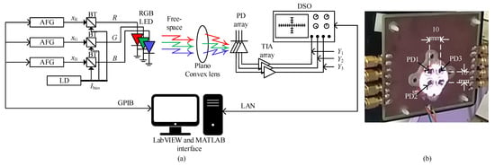
Figure 1.
(a) Defocused MIMO system block diagram. BT: bias tee, LD: laser driver, and (b) photograph of the defocused beam on the PD array.
The received signal is given by [1]:
where Y is a K × 1 column vector containing the received signals obtained for the current time sample on each of the independent PDs. H is the K × K CSI matrix. X is a K × 1 column vector encompassing the current independent transmit data stream samples (R, G, and B). N = [n1, n2, n3, …. nK]T is a K × 1 column vector representing the additive white Gaussian noise (AWGN) experienced by each Rx. Expanding (1), we have:
where hk,λ is the CSI coefficient for kth PD, and is given as:
where Pk(λ) is the transmitted optical power for the kth LED and λ is the wavelength. Note that CSI is defined by three main parameters (i) of PD, as shown in Figure 2a. Figure 2b shows (ii) LED’s E/O conversion efficiency. (iii) The line of sight (LoS) DC gain given by [1]:
where m is Lambertian order of emission of the LED, A is the PD’s active area, d is the transmission distance, and φ and ψ are the angles of irradiance and incidence, respectively. g(ψ) is the gain of the optical concentrator. Ψc represents the field of view (FOV) of the PD. The plot of the Si PD is depicted in Figure 2a, with the R (645 nm), G (529 nm), and B (469 nm) components highlighted at 0.45, 0.32, and 0.26 A/W, respectively. Figure 2b illustrates the normalized optical power as a function of the drive current for all three LEDs. It shows that R and B LEDs have similar current to power conversion profiles with the B LED exhibiting less linearity. The G LED exhibits a lower conversion efficiency and a non-linear behavior compared to the R and B LEDs.
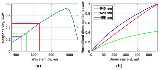
Figure 2.
(a) A typical Si PD responsivity curve and (b) normalized E/O conversion of the RGB LED.
Each of the CSI coefficients in this system is estimated by transmitting the PSs over a given time t and logged as the time-averaged amplitude. Note that the CSI coefficients are extracted using the double Gaussian curve fitting in MATLAB over a histogram of the received PS and by finding the amplitude between the maxima (Figure 3).
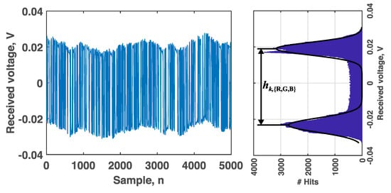
Figure 3.
CSI coefficient extraction hk,{R,G,B} from the transmitted pilot signal.
Following determination of CSI, parallel transmission of the data streams takes place, and the accumulative signal at the kth Rx is given by:
where nk is the AWGN at the kth Rx with zero mean and variance . Note that the background induced shot noise is the most dominant source with the variance given by [1]:
where q is the electron charge, Bef is the bandwidth of the electrical filter following the optical Rx, and Ibg is the background noise current.
A simple but not optimal approach to estimate the transmitted data in WDM systems is a receiver that eliminates all crosstalk. This is achieved using the decoding algorithm based on the ZF equalizer, which is shown to have almost identical performance to the more complex minimum mean squared error and the Vertical-Bell labs layered space–time (V-BLAST) beamformers in the LoS VLC MIMO system reported in [10]. The estimated transmitted data using the ZF equalizer is given by [10]:
The output of the ZF receiver is only a function of the desired signal and the noise multiplied by the filter coefficients. For the H matrix to be invertible, there needs to be a diversity between the CSI’s, which in this work is achieved along the rows through a combination of and E/O conversion of different LEDs. The diversity within the columns arises from the defocusing of the optical beam on the PD array, which covers an area slightly larger than the PD array and is intentionally positioned, so the center of the beam is offset from the array center. Thus, each PD is in a different position with respect to the center of the spot. A PD closer to the middle of the spot has a higher H(0) than one near to or on the edge. Positioning the spot in this manner increases the diversity between the CSI columns in the H matrix. This is demonstrated in the photograph of Figure 1b. Although the picture shows four PDs, only three are being used (PD1 to 3)
3. Experimental Setup
3.1. RGB LED Characterisation
The LEDs used for the RGB D-MIMO link have been characterized, as shown in Figure 4a–c, for the frequency response, relative spectral output and optical beam profile, and in Figure 2b for E/O conversion. The normalization factor in Figure 2b and Figure 4b,c have been set using the maximum output power levels at the peak wavelengths of 469, 529, and 645 nm. The frequency response was measured using an Agilent Technologies MXA Signal Analyser (N9020A). Each trace was normalized to 0 dB at the minimum test frequency of 1 MHz. The measured 3 dB bandwidths are 8.8, 7.6, and 7 MHz for the R, B, and G LED chips, respectively. The relative spectral profiles shown in Figure 4b display adequate isolation between wavelengths with a slight overlap between B and G LEDs. The RGB beam profile (Figure 4c) shows that both the B and R beams are skewed to the right and left, respectively, whereas the G beam is centered to the normal. Skewing of the B and R can actually assist in the diversity of H matrix rows, given that CSI is also dependent on the irradiance and illuminance angles (φ, ψ) as described in (4). Figure 4d highlights the relative positions of the colored chips on the LED die. The LED has a dome lens covering it, which could explain the skew experienced by the R and B wavelengths since they are both positioned off-center.
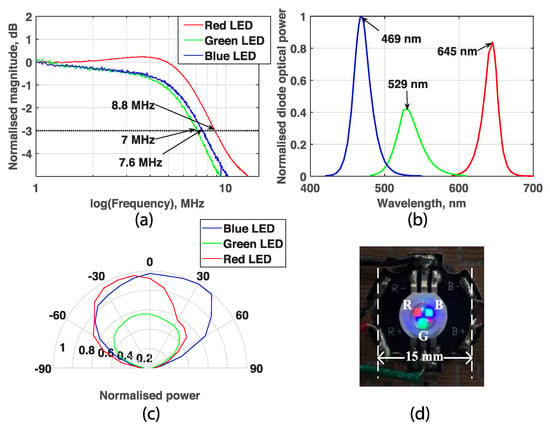
Figure 4.
RGB LED: (a) normalized frequency response; (b) power profiles; (c) beam profile; and (d) LED.
3.2. System under Test
The experimental block diagram is shown in Figure 1. LabVIEW was used to control both the arbitrary function generators (AFGs, Tektronix AFG3252) and digital storage oscilloscope (DSO, Keysight DSO9254A) via GPIB and LAN connections, respectively. Three independent pseudo-random binary sequences (PRBS) (xR, xG, xB) of length 210−1 were uploaded onto the separate channels of the AFG’s via the GPIB interface for intensity modulation of each of the RGB chips via a bias tee. A bias current IB of 300 mA was applied to each LED chip through the laser driver (LD) to maintain constant illumination. Following, free-space transmission through a 75 cm LoS channel, at the Rx a 10 cm plano-convex lens was used to launch the light beam onto the PD (Osram OSD15-5T) array (Figure 1b), the output of which was AC coupled to transimpedance amplifiers (TIA, AD8015). The regenerated electrical signals Yk were captured using the DSO and then uploaded to the PC via the LAN cable for off-line processing. Using MATLAB, the signals are low-pass filtered (LPF) at the bit rate RB, prior to being processed into either the CSI coefficients or demultiplexed into estimates of the transmitted data. For the experiments, RB of 5 Mb/s per channel was chosen, as this lies comfortably within the LED Bmod.
4. Experimental Verification
Each of the OOK-NRZ data streams, including the PSs, at RB of 5 Mb/s are captured at a sampling rate fs of 50 MS/s. Following the PS transmission period, where three independent PRBS of 104 bits were captured and analyzed using the CSI coefficient extraction method explained in Section II, the measured H matrix is given by:
From (8) it can be seen that the 2nd column (λG) is significantly lower than the 1st and 3rd (i.e., λR and λB) for each of the Rx (i.e., rows). This is due to the considerably lower E/O conversion factor for the G LED chip (Figure 2b). Results for the estimated data (xRest, xGest, xBest) of the D-MIMO are shown in Figure 5, where (a), (c), and (e) display the transmitted and estimated data streams for λR, λB, and λG, respectively, whereas (b), (d), and (f) show their respective eye diagrams. As in the PS, the estimated waveforms shown in Figure 5a,c,e display the baseline wander [17], which is attributed to the AC coupling at the transmitter due to the use of bias tees and AC coupling between PDs and TIAs at the Rxs. Nevertheless, the estimates of the transmitted data show a good correlation with the original data sets.
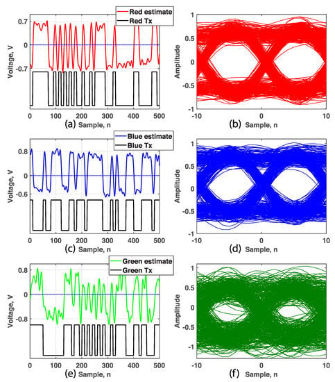
Figure 5.
Transmitted and estimated data with the corresponding eye diagrams of the estimated data for: (a,b) the λR, (c,d) λB, and (e,f) λG.
While using the ZF algorithm, the amplitudes of all estimated data sets are normalized. Furthermore, the eye diagrams for R and B LEDs display clear eye openings, whereas for the G LED, the eye is less open and is much closer to the noise floor. This can be attributed to the lower E/O conversion (Figure 2b) and the optical beam profile (Figure 4c), thus resulting in a lower received power level, hence the reduced signal-to-noise ratio (SNR). This is also proven in (8), where the PSs for the 2nd column are almost half that of the 1st and 3rd columns. Using the equations outlined in [1], the estimated Q-factor (sampled at the midpoint of each bit) and the statistical BER (derived from Q-factors) for λR, λB, and λG are given in Table 1. Both λR and λB fall within the 7% forward error correction (FEC) BER limit of 3.8 × 10⁻³, with λG failing to meet the FEC limit. However, with more G LEDs, the SNR will increase and the FEC will be satisfied.

Table 1.
Q-factor and statistical BER.
5. Conclusions
In this paper, we experimentally demonstrated, for the first time, a defocused MIMO setup that removed the need for optical bandpass filters in WDM links. The proposed system is based on using the natural diversity of the individual LEDs within a single device to generate a H-matrix, which is not dependent on spatial diversity but on the wavelength-dependent optical power levels. Through this exploitation, the different data streams from the different LEDs can be successfully recovered without any dichroic filters, substantially reducing the system cost. We showed that using the simple ZF technique, the aggregated data was successfully demultiplexed into estimates of the original transmitted signals. For the OOK-NRZ data sets, the measured Q-factors were sufficient for error free transmission, with Q-factors above 7.66, 7.69, and 4.75 dB for λR, λB, and λG, respectively.
Author Contributions
Conceptualization, A.B.; methodology, A.B. and P.A.H.; validation, A.B., P.C., and P.A.H.; formal analysis, A.B.; investigation, A.B., P.C., and P.A.H.; funding acquisition, Z.G. and S.Z.; writing—original draft preparation, A.B., P.C., and P.A.H.; writing—review and editing, Z.G. and S.Z. All authors have read and agreed to the published version of the manuscript.
Funding
This project is supported by the UK EPSRC grant EP/P006280/1: MARVEL and the EU Cost Action NEWFOCUS CA19111 and CTU project SGS20/166/OHK3/3T/13.
Conflicts of Interest
The authors declare no conflict of interest.
References
- Ghassemlooy, Z.; Popoola, W.; Rajbhandari, S. Optical Wireless Communications: System and Channel Modelling with MATLAB®, 2nd ed.; CRC Press: Boca Raton, FL, USA, 2019. [Google Scholar]
- Karunatilaka, D.; Zafar, F.; Kalavally, V.; Parthiban, R. LED based indoor visible light communications: State of the art. IEEE Commun. Surv. Tutor. 2015, 17, 1649–1678. [Google Scholar] [CrossRef]
- Bian, R.; Tavakkolnia, I.; Haas, H. 15.73 Gb/s visible light communication with off-the-shelf LEDs. J. Lightwave Technol. 2019, 37, 2418–2424. [Google Scholar] [CrossRef]
- Chang, C.; Wu, C.; Choi, B.I. WDM-VLC receiver sensors: Large-Scale filter-array detectors with optimized selection combining methods. IEEE Sens. J. 2018, 18, 2411–2420. [Google Scholar] [CrossRef]
- Rajbhandari, S.; Jalajakumari, A.V.N.; Chun, H.; Faulkner, G.; Cameron, K.; Henderson, R.; Tsonev, R.; Haas, H.; Xie, E.; McKendry, J.J.D.; et al. A multigigabit per second integrated multiple-input multiple-output vlc demonstrator. J. Lightwave Technol. 2017, 35, 4358–4365. [Google Scholar] [CrossRef]
- Werfli, K.; Chvojka, P.; Ghassemlooy, Z.; Hassan, N.B.; Zvanovec, S.; Burton, A.; Haigh, P.A.; Bhatnagar, M.R. Experimental demonstration of high-speed 4 × 4 imaging multi-cap mimo visible light communications. J. Lightwave Technol. 2018, 36, 1944–1951. [Google Scholar] [CrossRef]
- Nuwanpriya, A.; Ho, S.; Chen, C.S. Indoor MIMO visible light communications: Novel angle diversity receivers for mobile users. IEEE J. Sel. Areas Commun. 2015, 33, 1780–1792. [Google Scholar] [CrossRef]
- Chen, C.; Zhong, W.; Wu, D. Non-hermitian symmetry orthogonal frequency division multiplexing for multiple-input multiple-output visible light communications. IEEE/OSA J. Optical. Commun. Netw. 2017, 9, 36–44. [Google Scholar] [CrossRef]
- Lin, B.; Tang, X.; Ghassemlooy, Z. Optical power domain NOMA for visible light communications. IEEE Wirel. Commun. Lett. 2019, 8, 1260–1263. [Google Scholar] [CrossRef]
- Burton, A.; Minh, H.L.; Ghassemlooy, Z.; Bentley, E.; Botella, C. Experimental demonstration of 50-Mb/s visible light communications using 4 × 4 mimo. IEEE Photonics Technol. Lett. 2014, 26, 945–948. [Google Scholar] [CrossRef]
- Chen, C.; Zhong, W.; Yang, H.; Du, P. On the performance of MIMO-NOMA-Based visible light communication systems. IEEE Photonics Technol. Lett. 2018, 30, 307–310. [Google Scholar] [CrossRef]
- Dong, F.; Singh, R.; O’Brien, D. Adaptive MIMO-VLC System for High Data Rate Communications. In Proceedings of the 2020 IEEE Globecom Workshops, Taipei, Taiwan, 8–10 December 2020; pp. 1–6. [Google Scholar]
- Lu, I.; Lai, C.; Yeh, C.; Chen, J. 6.36 Gbit/s RGB LED-based WDM MIMO Visible Light Communication System Employing OFDM Modulation. In Proceedings of the Optical Fiber Communications Conference and Exhibition (OFC), Los Angeles, CA, USA, 19–23 March 2017; pp. 1–3. [Google Scholar]
- Omura, N.; Higashi, A.; Yabuuchi, J.; Iwamatsu, T.; Oshiba, S. Experimental Demonstration of OFDM Based WDM-MIMO Visible Light Communication System. In Proceedings of the Asia-Pacific Microwave Conference (APMC), Kyoto, Japan, 6–9 November 2018; pp. 872–874. [Google Scholar]
- Vs, R.K.; Djordjevic, I.B. MIMO-WDM Visible Light Communications Based on Commercial RGBA LEDs. In Proceedings of the 20th International Conference on Transparent Optical Networks (ICTON), Bucharest, Romania, 1–5 July 2018; pp. 1–5. [Google Scholar]
- Wang, Y.; Zhou, Y.; Gui, T.; Zhong, K.; Zhou, X.; Wang, L.; Lau, A.P.T.; Lu, C.; Chi, N. Efficient MMSE-SQRD-Based MIMO Decoder for SEFDM-Based 2.4-Gb/s-Spectrum-Compressed WDM VLC System. IEEE Photon. J. 2016, 8, 1–9. [Google Scholar] [CrossRef]
- Hayes, A.R.; Ghassemlooy, Z.; Seed, N.L.; McLaughlin, R. Baseline-wander Effects on Systems Employing Digital Pulse-interval Modulation. IEE Proc. Optoelectron. 2000, 147, 295–300. [Google Scholar] [CrossRef][Green Version]
- Correa, C.; Huijskens, F.; Tangdiongga, E.; Koonen, A. POF Feeding in Li-Fi Systems with MIMO Approach. In Proceedings of the 24th Annual IEEE Photonics Benelux Symposium 2019, Amsterdam, The Netherlands, 21–22 November 2019. [Google Scholar]
Publisher’s Note: MDPI stays neutral with regard to jurisdictional claims in published maps and institutional affiliations. |
© 2021 by the authors. Licensee MDPI, Basel, Switzerland. This article is an open access article distributed under the terms and conditions of the Creative Commons Attribution (CC BY) license (https://creativecommons.org/licenses/by/4.0/).