Article

Neutral Point Clamped Transformer-Less Multilevel Converter for Grid-Connected Photovoltaic System

1
Department of Electrical and Electronics Engineering, Alagappa Chettiar Government College of Engineering and Technology, Karaikudi 630003, Tamil Nadu, India
2
Electrical Engineering Department, King Khalid University, Abha 62529, Saudi Arabia
3
Department of Electrical and Electronics Engineering, School of EEE, Sathyabama Institute of Science and Technology, Chennai 600119, Tamil Nadu, India
4
Department of Electrical and Electronics Engineering, K S R Institute for Engineering and Technology, Namakkal 637215, Tamil Nadu, India
5
Department of Electrical and Electronics Engineering, Adhiparasakthi Engineering College, Kalavai 632506, Vellore, India
6
Department of Electrical Engineering, Tshwane University of Technology, Pretoria 0001, South Africa
7
Department of Electrical and Electronics Engineering, SRM Institute of Science and Technology, Chennai 603203, Tamil Nadu, India
8
Faculty of Engineering, Østfold University College, Kobberslagerstredet 5, 1671 Kråkeroy-Fredrikstad, Norway
*
Authors to whom correspondence should be addressed.
Electronics 2021, 10(8), 977; https://doi.org/10.3390/electronics10080977
Submission received: 12 February 2021 / Revised: 5 April 2021 / Accepted: 13 April 2021 / Published: 19 April 2021

Abstract

:
Transformer-less (TL) inverter topologies have elicited further special treatment in photo-voltaic (PV) power system as they provide high efficiency and low cost. Neutral point clamped (NPC) multilevel-inverter (MLI) topologies-based transformer-less are being immensely used in grid-connected medium-voltage high-power claims. Unfortunately, these topologies such as NPC-MLI, full-bridge inverter with DC bypass (FB-DCBP) suffer from the shoot-through problem on the bridge legs, which affect the reliability of the implementation. Based on the previous above credits, a T type neutral point clamped (TNP)—MLI (TNP-MLI) with transformer-less topology called TL-TNP-MLI is presented to be an alternate which can be suitable in the grid-connected PV power generation systems. The suggested TL-TNP-MLI topologies free from inverter bridge legs shoot-through burden, switching frequency common-mode current (CMC), and leakage current. The control system of the grid interface with hysteresis current control (HCC) strategy is proposed. The effectiveness of the proposed PV connected transformer-less TNP-MLI topology with different grid and PV scenario has been verified through the MATLAB/Simulink simulation model and field-programmable gate area (FPGA)-based experimental results for a 1.5 kW system.

1. Introduction

Renewable energy sources (RES) are a current asset for the electric power generation. Photovoltaic (PV), fuel cells, and wind turbines are the most popular among the renewable sources. After thumping about 260 GW of PV power installed capacity by the end of 2014, global PV generation power is expected to hit 400 GW soon [1,2]. All PV modules generate parasitic earth capacitance (CPV) approximately 1–2 μF/kW in the middle of the PV modules and their ground. As a result, any PV connected high-frequency inverter/converter suffers from a high leakage current which emanates from the PV system [3,4]. To avoid this problem, a low-frequency isolated transformer is directly associated in the middle of the PV-tied inverter and grid. Hence PV modules are grounded directly, which guarantees the grid and PV inverter own safety aspects, and output voltage requirements and conquers the photovoltaic dc-component in the grid. By overcoming the transformer usage issue, researchers have proposed different PV-powered transformer-less (TL) inverters for PV-tied grid-connected power system for both single and three phases [5,6,7].
In this connection, neutral-point-clamped multilevel inverter (NPC-MLI) is broadly espoused in TL PV-tied systems [8,9,10,11,12]. The NPC-MLI topology can defeat the inconvenience of common-mode leakage current which limits the DC component injection in the grid [13]. Three-level NPC-MLIs are vastly used in motor control and PV-grid-connected applications compared to higher level MLIs. The NPC-MLI uses the number of switches and clamping diodes and provides the multiple voltage levels through the different phases. The DC-link capacitor is connected in series and split the DC-link voltage equally to make the voltage levels in the output. The level increases in the NPC-MLI are constructed by increasing the DC-link capacitors, clamping diode, and increasing the switches. The main drawback of the NPC-MLI is maintaining the DC-link capacitor balancing. Hence the NPC-MLI topologies are limited to the three levels [8].
The paper [14] Xiao et al. investigated the detailed analytical model of leakage current for PV-powered grid-connected single-phase transformer-less inverter. With this idea, Gonzalez et al. has deliberated the ideology and characterized elimination of leakage current for PV-grid-connected TL single-phase NPC-MLI system [15]. The prevention of the shoot-through problem on the inverter bridge legs is worth in view of the reliability enhancements to NPC-MLI. The dual-buck half-bridge inverter (DB-HBI) can evade the shoot-through issue, which was proposed in [16]. However, DB-HBI is able to work with the bipolar modulation strategy only, which results in enormous voltage stress upon power devices. In order to resolve these problems, MLI configuration was established [17,18], which is capable of working at higher efficiencies. Based on half-bridge-type TL inverter, Huafeng et al. have proposed PV-grid-associated single-phase split-inductor-based transformer-less NPC-MLI using a variable and fixed hysteresis band with no leakage current and shoot through problems with reasonable transient and steady-state performance [19].
Nevertheless, in this topology operation, the zero vector (0110) and non-zero vector (1100, 0011), the current paths contain two power devices. More importantly, the reported inverter current commutation involves all four IGBTs, which leads to a high power conversion loss and the higher converter switches conduction loss. Though NPC-MLI is much stable for transformer-less PV-based RES, it habitually operates in the range of lower power instead of rated power low/medium power. NPC-MLI looks prominent since their IGBT and diode have comparatively higher state voltage/current ratio in the range of low and medium powers [20,21,22]. Alternatively, another inverter in NP-MLI family called T shape neutral point MLI called T type NPC (TNP-MLI) is being studied more and more to increase the efficiency of the system [23,24]. Efficiency of the TNP-MLI is superior to TNP-MLI [23]. Schweitzer et al. in [25] estimated the power loss and control performance of three-level TNP-MLI and underlined with a 10-kW hardware prototype. The authors in [26] dealt with TNP-MLI for PV application with two separate MPPTs for the DC-Link and investigated conduction loss for the inverter. Some similar structure of T type MLI with different PWM scheme is also discussed in [27,28,29,30]. The NPC-MLI majorly suffered by DC-link capacitors balancing. There are numerous papers published in literature. A few concentrate on the self-balancing idea with capacitors voltage switching ripple reduction as well. The self-balancing method is investigated in three-level NPC-MLI using carrier-based modulation [31,32,33,34,35,36,37,38]. The same self-balancing method nearest three vector selection is used in Hybrid Neutral Point Clamped transformerless inverter [39,40]. In [41], a modified SVM method is suggested with over modulation operation using small, medium, and zero vector switching vectors for mitigating the zero-sequence circulating current. In [42], the new CMV-eliminated SVM coordinate system is proposed. This method uses simple mathematical calculation to locate the reference vector and its nearest three CMV vectors duty cycles. However, in this method the inverter maximum output voltage is restricted up to VDC/2. Similarly, in [43] a method is investigated to yield output voltage more than VDC/3, the amplitude of CMV could reduce only until 33% from the total CMV. Most importantly these CMV elimination methods affect the DC-link capacitors charging and discharge characteristics, which cause the large harmonics in the inverter output voltage and current waveforms. Current controller is the foremost request for grid-connected inverters. There are varieties of current controller discussed in the literature [32]. Based on the aforementioned discussion the PV-grid-connected TL NPC inverters should have improved inverter performance without any shoot-through burden on the inverter legs, commendable current controller, proper PWM to take care of the harmonics, switching frequency common-mode current (CMC), and leakage current.
The proposed TL-TNC-MLI has a simple structure with a PV-connected grid system using suitable hysteresis current control method to control the split inductor current of the grid. The hysteresis current control strategy directly measures the error current and functioning of the inverter switching pulses regarding PV output and grid situations. The systems proposed in this paper are aimed at proposing the TNP-MLI concept in single-phase transformer-less grid-connected system without shoot through and no switching frequency common-mode voltage issue. MATLAB/Simulink simulations confirm the proposed arrangements and experimentations of FPGA-based 1.5 kW PV tied TL-TNP-MLI grid-connected setup.

2. Analysis of Transformer-Less Multilevel NPC-MLI

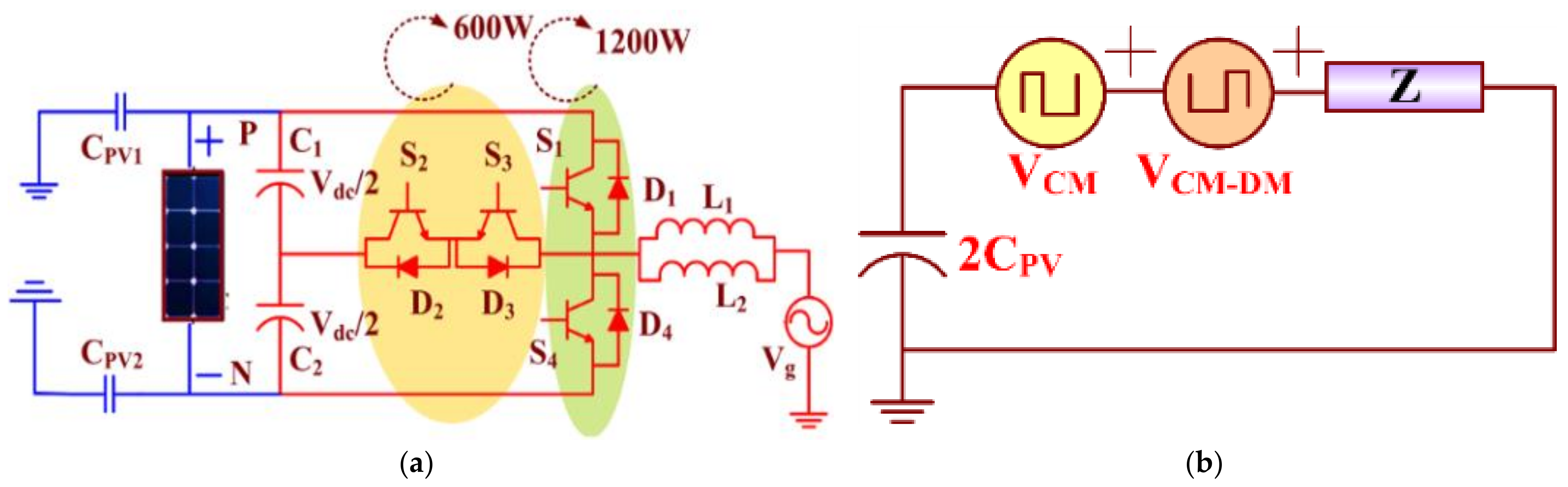
2.1. Single-Phase Three-Level Transformer-Less Multilevel NPC-MLI

In general, a PV-based inverter functions under a considerably lower power range than the rated power. Besides, as conversed in the introduction, the NPC-MLI schemes seem more prominent since the IGBTs and diodes have comparatively larger state voltage/current ratio at the range of low and medium powers. Therefore, TNP-MLI is adequate for PV applications and power circuitry as shown in Figure 1a. Here, the clamping diodes (D1–D2) are absent, and it contains only 4-semiconductors (4-IGBTs: (S1–S4), 4-anti-parallel diodes (FWD: Da1–Dc4), and two dc-link capacitors (C1 and C2). Considering medium power TNP-MLI topology, top and bottom switches (S1/D1 and S4/D4) work with 1200 V, and middle switches (S2/D2 and S3/D3) operate only at 600 V (half of the top and top and bottom switch voltage range). Unlike three-level DC-MLI, no series association of devices has to block the whole dc-link voltage Vdc [24]. In the proposed TNP-MLI transformer-less topology the mid-point (C) of two DC-link/neutral point capacitors (VC1 and VC2) connects to the PV cluster mid-point and grid neutral (G). Table 1 shows the commutation interval, voltage and current path for TNP-MLI for inverting and rectifying modes.

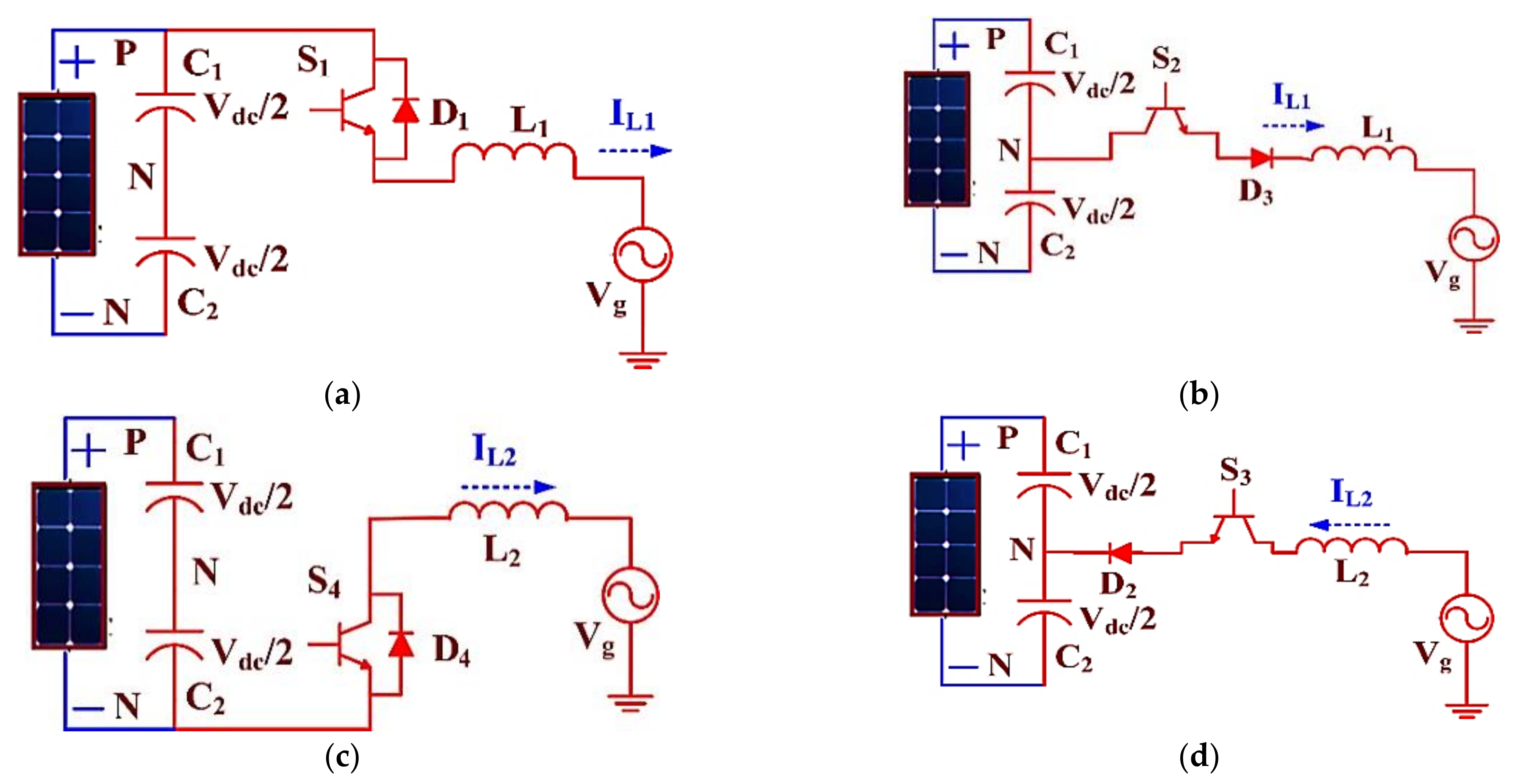
2.2. Single Modes of Operation in PV-Tied Single-Phase Three-Level Transformer-Less TNP-MLI Topology

The inverter switching frequency CMV of transformer-less PV inverter remains the birthplace of the leakage current coming from the inverter and the load ground [14,15]. In this system, there is a parasitic capacitance of the PV array (CG-PV) associated between common-ground and PV. However, in TL inverters, this switching frequency CMV behavior is significantly present, which leads to leakage ground currents on the inverter [4,10]. Hence, the inverter switching operation or topology structure must be investigated with respect to high-frequency CMV.
The proposed TL-TNP-MLI topology investigates the simplest CMV, and DMV based on the paper [15,26] and the PV-fed TL-TNP-MLI equivalent circuit illustrated in Figure 1b. Here, the DMV (VDM) to CMV (VCM) influence by VCM_DM, is equal to −VDM/2.
During a positive half-cycle,
V C M _ D M = V D M 2
V C M _ D M = V A N + V C N 2
V D M = V A N V C N
During a negative half-cycle,
V C M = V B N + V C N 2
V D M = V B N V C N
The total CMV, including VCM_DM
V T C M = V C M + V C M _ D M
The various possible switching operations of PV-tied TL- TNP-MLI are investigated for positive as well as negative half-cycle of grid voltage, as displayed in Figure 2a–d. Before going to the modes of operation, the following assumptions are made: (1) all IGBTs (S1–S4) are considered as ideal devices; (2) DC-link capacitors (C1 = C2 = VPV/2) equally divide the DC-link voltages; and (3) the inverter operates at unity power factor (PF), i.e., inverter current iL and grid voltage (Vg) are in zero degrees phase shift.
Mode 1 (S1 is ON, and S2, S3, and S4 are OFF): Now voltage across the capacitor C1 (VC1), i.e., VCA = (1/2) VPV supply to the grid via L1. During this period, inductor L1 current (iL1) increases to L 1 d i L 1 d t
L 1 d i L 1 d t = 1 2 V P V V g V A M = V P V ; V B M = V g 1 2 V P V ; V C N = 1 2 V P V V D M = 1 2 V P V ; V C M = 3 4 V P V ; V C M _ D M = 1 4 V P V ; V T C M = 1 4 V P V ;
Mode 2 (S2 is ON, and S1, S3, S4 are OFF): During this mode, zero potential points connected to the grid and output voltage of the bridge leg are zero, i.e., VCA = 0. During this period, iL1 starts to decrease to zero.
L 1 d i L 1 d t = 0 V g V A M = 1 2 V P V ; V B M = V g ; V C N = 1 2 V P V V D M = 0 ; V C M = 1 2 V P V V C M _ D M = 0 ; V T C M = 1 2 V P V
Mode 3 (S4 is ON, and S1, S2 and S3 are OFF): Now voltage across the capacitor C2 (VC2), i.e., VCB = (1/2)VPV supply to the grid via L2. At this period, inductor L2 current (iL2) increases to L 2 di L 2 dt .
L 1 d i L 1 d t = 1 2 V P V V g V A M = V g 1 2 V P V ; V B M = 0 ; V C N = 1 2 V P V V D M = 1 2 V P V ; V C M = 1 4 V P V V C M _ D M = 1 4 V P V ; V T C M = 1 2 V P V
Mode 4 (S3 is ON, and S1, S2, S4 are OFF): During this mode, the zero potential points connected to the grid and output voltage of bridge leg is zero, i.e., VCB = 0. During this period, iL2 starts to decrease to zero.
L 1 d i L 1 d t = 0 V g V A M = V g ; V B M = 1 2 V P V ; V C N = 1 2 V P V V D M = 0 ; V C M = 1 2 V P V V C M _ D M = 0 ; V T C M = 1 2 V P V
During the commutation modes, unlike NPC-MLI, “short” or “long” commutation paths are not present in TNP-MLI topology; all paths are having the same geometric length and have one outer switch (indices 1 or 4; either IGBT or diode) and two inner switches (either T2 and D3 or T3 and D2). Table 2 shows the commutation interval voltage and the current path for the four operating modes (positive voltage and positive current, a positive voltage and negative current, negative voltage and negative current, and negative voltage and positive current).
The TL-TNP-MLI providing uniform voltage transition (zero to +VPV/2 and zero to zero −VPV/2) according to positive as well as negative half-cycle of grid voltage, which diminishes current ripple of inductor naturally, and hence TL-TNP-MLI requires less inductance range compared to the dual-buck half-bridge inverter [16]. Besides, based on the CMV calculation on the different mode of the inverter, it could be understood that the proposed transformer-less TNP-MLI produces constant VTCM, and it will not have any leakage current. This benefit comes about from the MLI topology structure naturally produces less CMV compared to other inverters [24].
The proposed TL-TNP-MLI topology compared with conventional ones is presented in the Table 2. Inverter efficiency performance is considered with different switching frequency ranges from 2 kHz to 25 kHz. The efficiency of the TL-TNP-MLI is stupendous under medium switching frequencies from 3 kHz to 20 kHz. Here, the significant improvement of the T type NPC topology is reduction in their switching losses as the commutation voltage of the 1200-V IGBTs is only 350 V instead of 700 V. When switching frequency is above 20 kHz, the NPC-MLI topology gave a better performance. Noteworthy, the low-voltage application is like the PV-grid-connected system; the TL-TNP-MLI is the best choice concerning cost and efficiency.
To summarize, in both I-Type and T- Type NPC MLIs, the zero vector’s conduction loss leads to the entire conduction losses besides even the complete semiconductor power losses. Nevertheless, the T- Type NPC MLI only improves the T- Type NPC MLI non-zero vector conduction losses, as well as the current path of T-type zero vectors is the same as that of I-type. Thus, the T-type improvement over I-type is considerably restricted due to the unimproved zero-vector conduction loss.
Diode Free NPC-MLI, four CoolMOSFETs replace the IGBT and diode middle bidirectional switch. In the proposed topology, there is no diode involved in the current path supposing the unity power factor. In all the compared topologies the inner and outer power switches need 1200 V operation voltage, however the proposed one needs only 600 V in both inner and outer power switches. Unlike the conventional MLIs, Shoot through Short circuit problems is not there in the proposed one.

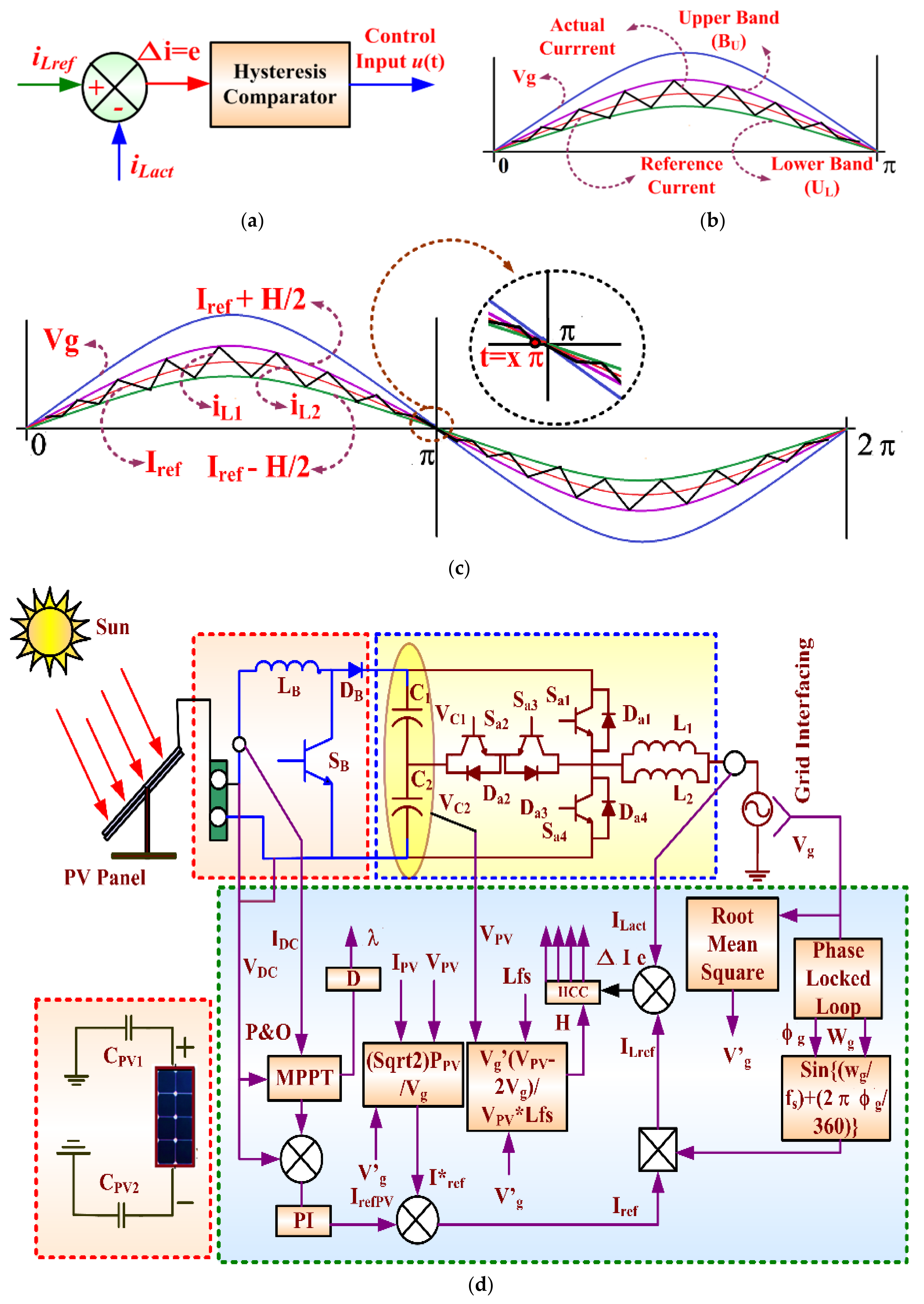
3. Control System of PV Grid Tired Connected Transformer-Less TNP-MLI

The controlling of the inductor current, and improved current controller (CC) to take care of the inductor charging and discharging nature to avoid the shoot through problem in inverter bridge legs are much appreciated for this proposed TL-TNP-MLI.

3.1. Design

The hysteresis current controls (HCCs) have precise tracking competence to track the inverter current with the grid voltage to ensure unity PF and current waveform quality [31]. Figure 3a displays the structure block diagram of HCC. Here, the reference current (iref) which is associated with actual current iact creates the error current ( ε i ) = (iLref − iLact), and yields the control input u (t) among two hysteresis bands: upper hysteresis bands (UU) and lower hysteresis bands (BL) [28,29,30,31]. Such control input u(t) drives the PWM block to give the perfect interface between inverter and grid. The challenge here is to maintain the iact close to the iref inside the hysteresis boundaries [9]. To ensure that, the proposed grid-connected TL-TNP-MLI interface is investigated with HCC to verify zero iL (inverter current) sooner than the zero-crossing of grid voltage “Vg”. Figure 3b illustrates the hysteresis switching assortment for the proposed HCC.
According to Figure 3c, the x point has been chosen just before π (x should be less than 180°). The interval between x to xπ is chosen more than the switching frequency (fs) to avoid the pulse dropping.
x π π [ V g s i n ( w t ) + V S ( O N ) ] L i r e f s i n ( x π ) + H 2
Here, VS(ON) = ON-state voltages of power switch iref is current grid reference, H = bandwidth of HCC, and L = filter inductor. Fixed frequency HCC is achieved by computing hysteresis bandwidth H from temporary value of the Vg and variable PV array output voltage VPV. Hence the “H” is calculated based on the ripple of the inductor current, the transient value of the grid voltage Vg, filter inductor L, switching frequency fs, and the output voltage of PV array VPV. The fixed frequency bandwidth of HCC,
H = V g ( V P V 2 V g ) V P V L f s
Here the filter has been chosen based on the inductor value since the filter design is highly difficult for high stability, and fast dynamic response nonlinear controller HCC. Few researchers have investigated on hysteresis band calculation including filter inductance [33]; among them the real-time hysteresis regulator design built on the switching frequency is the successful technique to estimate the H value.

3.2. Closed-Loop PV Tie Grid-Connected Control Strategy of Proposed Transformer-Less TNP-MLI

The suggested grid-connected PV connected TL-TNP-MLI control blocks representation is shown in Figure 3d. Here, the system is classified into four modules, namely; PV module, boost converter, TL-TNP-MLI, and grid interfacing control system. In the solar module, the measurement of PV voltage and current is given to P&O technique centered MPPT.
The PLL is implemented on the grid side to calculate the grid angle ϴg and utility grid nominal frequency (wg = 2πfo), fo is grid voltage frequency for the grid synchronization. Here, the most straightforward zero-crossing detection (ZCD) algorithm has been used. The grid voltage RMS (Vg′) is measured and given to the Iref* estimated block, where Iref* sampling from VPV, IPV, and RMS values of grid voltage Vg′ are as shown below,
I r e f * = 2 V P V V g
The Iref* is compared with PV reference current (IPV-ref) and estimating the final grid reference current dc- component (Iref), which is multiplied with sin ((wg + fs) + (2π ϴg/360)) to calculate the final grid reference current (Iref). Here, this Iref is also called an inductor reference current (ILref). The actual inductor ILact and ILref gives the error of inductor current ΔLie based on the ε i = (iLref − iLact), finally, the calculated real-time hysteresis band H using (12) and ΔLie gives gate pulses for the inverter switch (S1 to S4).

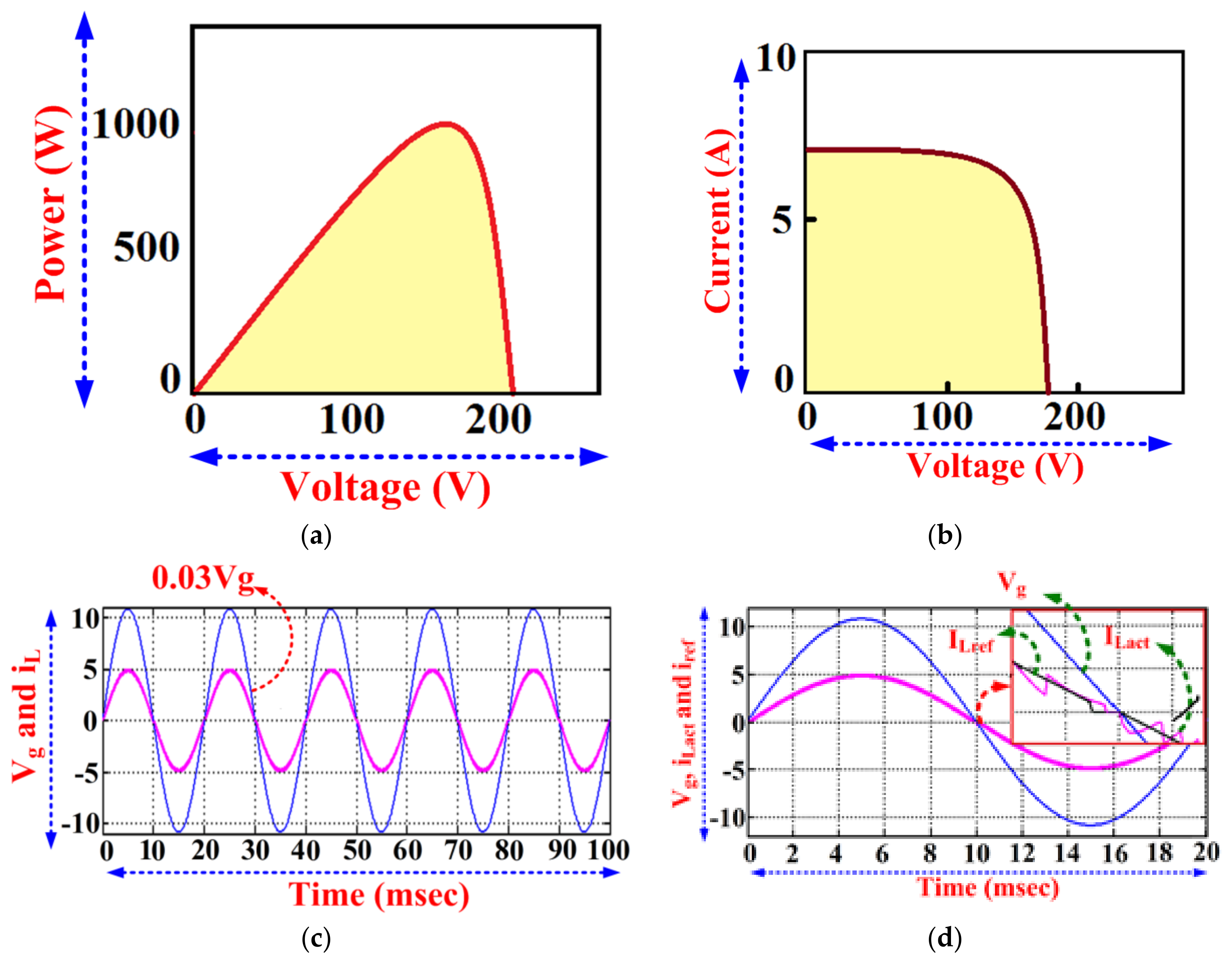
4. Numerical Simulation Results

To verify the validity of the proposed grid-connected PV-fed TL-TNP-MLI method, the simulation model is customized using MATLAB/Simulink (Table 3 simulation parameters). The 1.5 kW PV array module was modeled with P&O MPPT algorithm, functioned at different irradiation and temperature. The Figure 4a,b shows the PV module simulation results, here the P&O MPPT controller tracks PV array MPP within the range of 1.5 times of the grid frequency. For simulation analysis of the proposed inverter with HCC, 240 V input voltage (dc-link) is maintained from PV-connected boost converter and it is adequate to inject current into grid, as the Vg is taken as 230 V. Range of switching frequency is from 5 kHz to 40 kHz. The main objective of the proposed grid interfacing is explained through the validation results of inductor current (iL), and grid voltage (Vg) projected in the same scale as shown in Figure 4c. Here, Vg is multiplied by 0.03 to bring in-shape the grid voltage Vg with load current IL to view both on the same scale. From the waveform, it is understood that Vg and IL are meeting each other in the same zero-crossing point and ensuring the grid synchronization. By using the zoomed view on the zero-crossing point in Figure 4d, the HCC prevents the high-frequency signal just before the Vg reaching zero scales, as shown in Figure 4d. Figure 5a shows the inductor current (iL1 and iL2) and Figure 5b illustrates the current tracking between actual inductor ILact (inverter current) and grid current reference ILref.
Figure 6a,b shows the waveforms of inverter current and grid voltage with harmonic spectrum of the inverter current single-phase PV-fed grid-connected transformer-less TNP-MLI operating under fixed and variable hysteresis band H. Here, the spectrums are worked out till 500th order (25 kHz/50 Hz); it can be seen the THD percentage for both fixed and variable band are less as 5% and 8% respectively.
The inductor current accomplishes the ability of tracking with high-precision of the given current reference concerning PV and grid variations. According to grid interfacing international standards (UL1741 and NEC690), inverter and its controllers must be capable of connecting to the grid with all protections. To ensure this decisive factor, the proposed grid interface is tested with different variation in PV and grid, as shown in Figure 7. From Figure 7a–c, it could be understood that, once the inverter switching pulses are turned OFF, then the inverter import to the grid stopped. Next, the study is performed for the dynamic conditions such as a sudden upsurge and fall on PV input voltage, grid voltage, and grid-current reference, as shown in Figure 8a–c, respectively. In Figure 8c the grid current drops from 3.5 to 1.8 msec and at 6.8 msec, the actual current touches the reference current iref using constant frequency variable hysteresis band H for 1/5 of the grid frequency interval itself. Figure 8c also displays the closest view of inverter current and reference current while there is a sudden variation in the grid current. In the same way when the Vg and PV input voltage change suddenly (see Figure 8a,b), the inverter interfacing algorithms on HCC respond rapidly to get the actual load current match the reference current.
Finally, the common-mode current (leakage current, ileakage) is measured between PV ground and grid common ground, as shown in Figure 9a. The total CMV (TCM)) produced by the TL-TNP-MLI is a constant (PPV/2) for all the modes of operation. Hence leakage current observed here is very low (also almost zero). In this section, the TL grid-connected fitness of the proposed TL-TNP-MLI is presented in comparison with the other reported inverters such as DB-HBI, NPC-MLI, and TL-NPC-MLI. As shown in Table 4 the comparison considers various aspects of TL inverter requirements like the number of power devices (IGBT, FWD, and clamping diodes), voltage and current stress on the power switches, switching device power factor (SDPF), shoot-through issues, and leakage-current phenomena [19,34,35]. Based on Table 4, it could be realized that the DB-HBI and NPC-MLI are in pathetic circumstances at the shoot-through problem, whereas the TL-NPC-MLI and TL-TNP-MLI are well-positioned except the filter inductors.
The proposed TL-TNP-MLI is entirely prevailing over the DB-HBI and NPC-MLI. When comparing TL-NPC-MLI with TL-TPC-MLI, device count, and selection of switch rating is much lesser (clamping diodes are absent), which results in less total SDPF. Hence, TL-TPC-MLI has the rewards of reduced switching and conduction loss, resulting in less SDPF compared to other topologies. Figure 9b illustrates the measured efficiency versus the output power of the TL-TNP-MLI, which shows better performance throughout the power ranges. The calculated efficiency is derived based on the power and a loss calculation formula in [23]. The power analyzer Yokogawa (power accuracy of ± 0.02%) is used for measurements of power for the fixed RL-load (R = 10Ω, L = 4 mH). Here, calculated efficiency is more than the measured one (due to the unaccounted losses on cabling and screw resistances). Further measurements exposed the other loss components produced by cabling resistance.
Next, the TL-TNP-MLI and other comparable inverter efficiency performance is considered with different switching frequency ranges from 2 kHz to 25 kHz and plotted in Figure 9c. The efficiency is stupendous under medium switching frequencies from 3 kHz to 20 kHz. Here, the significant improvement of the T type NPC topology is reduction in their switching losses as the commutation voltage of the 1200-V IGBTs is only 350 V instead of 700 V. When switching frequency is above 20 kHz, the NPC-MLI topology gave a better performance. Noteworthy the low-voltage application like PV-grid-connected system; the TL-TNP-MLI is the best choice concerning cost and efficiency. The proposed TL-TNP-MLI also having few limitations; (i) the maximum switching frequency is limited to 50 kW. Whereas the soft switching TL inverter can be operated up to 100 kHz. (ii) The outside side filter inductor must be same, otherwise large amount of DC compound will be produced by the inverter. (iii) The proposed TL-TNP-MLI is single grounded. Hence, high frequency DC oscillation may occur when the inverter operating at higher switching frequencies.
Three-level NPC-MLIs are widely used in motor control and PV-grid-connected applications compared to higher level MLIs. The NPC-MLI uses the number of switches and clamping diodes and provides the multiple voltage levels through the different phases. The DC-link capacitor connected in series and split the DC-link voltage equally to make the voltage levels in the output. The level increase in the NPC-MLI is constructed by increasing the DC-link capacitors, clamping diode, and increasing the switches. It is the main drawback of the NPC-MLI in maintaining the DC-link capacitor balancing. Hence the NPC-MLI topologies are limited to the three levels [8].

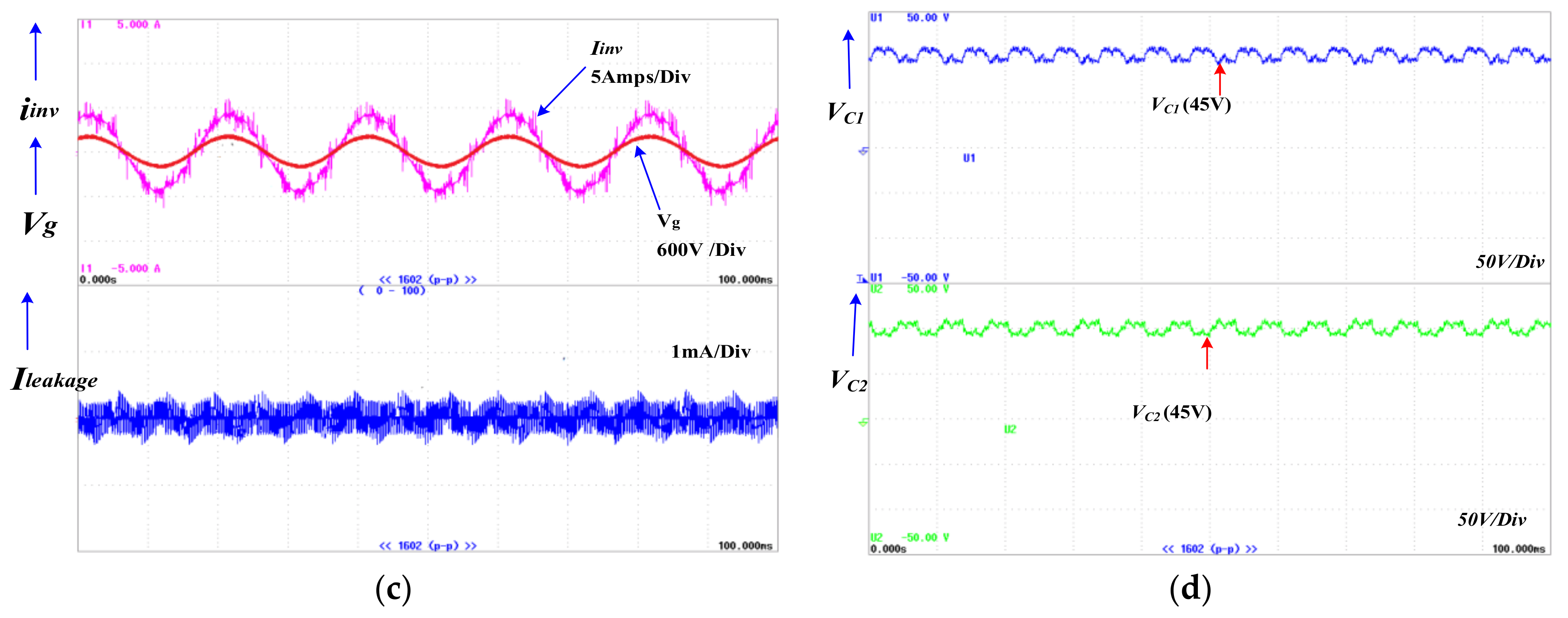
5. Hardware Implementation and Experimental Result

A 1.5-kW laboratory-scale prototype single-phase three-level TL-TNP-MLI is designed to verify the proposed PV-fed grid-connected system. Figure 10a displays the experimental setup of the proposed PV-fed grid-connected single-phase three-level TL-TNP-MLI. The existing designed three-phase TNP-MLI laboratory power module (Figure 10b) has been used for this proposed single-phase three-level TL-TNP-MLI by making use of their easy phase split options. Here, the bridge leg-1 switches (S1, S2, S3, and S4) are used for the proposed inverter (other switches are not used for the proposed work, they are totally isolated from supply and gate drivers). Here the outer switches (both the top and bottom switches (S1 and S4)) are Fairchild’s FGA15N120ANTD type, and the inner switches (S2 and S3) are Mitsubishi Nch IGBTCT60AM-18F. The 330 μF/450 V DC-link capacitors (C1 and C2) are chosen to maintain the inverter DC-link voltage as 400 V.
The switching frequency (fs) range is set from 3 to 25 kHz. At the nominal fs of 5 kHz, the inverter accomplishes a pure semiconductor efficiency of 99%. The additional power losses on the inverters are about 15 W, which are consumed by digital control and gate drive circuits. Initially, the inverter is tested with the PV system and boost converter for the constant DC-link voltage and when the HCC performance is confirmed with the prototype; a full-scale grid-connected transformer-less TNP-MLI was built and tested. All algorithms (MMPT, HCC, PWM, and grid interfacing) were implemented in a low-cost FPGA-Spartan-III processor through MATLAB/Simulink system generator. All the corresponding results were measured using a digital oscilloscope (Tektronix make) and power analyzer (Yokogawa make). Figure 10c indicates the inverter gate pulses of top and bottom switches (S1 and S4) via Tektronix DSO. All the inverter pulses are continually monitored and verified for the reliable operation of the inverter. Figure 11a shows the experimentation waveforms of inductor current (iL1 and iL2) of PV-tied grid-connected single-phase three-level TL-TNP-MLI. Here both the inductors (L1 and L2) are charging and discharging uniformly in opposite to one another. Figure 11b illustrates the inverter current (iL) and its harmonic spectrum.
The harmonic spectrum of iL is observed to be much similar to simulation value. Figure 11c shows inverter leakage current, grid voltage (Vg) and inverter current (iL). To show the zero phase shifts in between Vg and inverter current, the measurement of Vg and IL is done using the same scope window as 600 V/div and 5 A/div respectively. On the basis of waveform, it is seen that the Vg and IL are meeting each other in the similar zero-crossing point and ensure the inverter synchronization with grid. The leakage current of the proposed TL TNP-MLI is witnessed near to zero (20 mA). Figure 11d shows the two capacitor voltages (VC1 and VC2) the inverter DC-link. Besides, no much distortion is present in the inverter output current. The comparison of proposed inverter with existing inverter configuration. Is presented in Table 5. From the comparisons, it understands that the proposed TNP-MLI showing better choice for the TL inverter configurations.

6. Conclusions

This paper has presented an effective single-phase PV tied transformer-less three-level TNP-MLI grid-connected system designed as well as successfully implemented, with unique successfully implemented like assurances of no switching frequency. This TNP-MLI rallies better performance than NPC-MLI and another type of MLIs topologies, with its clamping diode-free circuit structure. The advantages of the proposed inverter with the PV tied TL application is compared with other inverter structures. Also, the proposed system confirms the healthier performance on steady-state and transient periods. MATLAB/Simulink simulations confirm the proposed arrangements and the experimentations of FPGA-based 1.5 kW PV-tied TL-TNP-MLI grid-connected setup.

Author Contributions

Conceptualization, P.M., C.B. and R.V.; methodology, P.M., C.B., L.M.-P. and R.V.; software, A.R., A.M. and R.U.; validation, P.M., C.B. and R.V.; formal analysis, P.M., C.B. and R.V.; investigation, P.M., C.B. and R.V.; resources, J.L.M., R.V.; data curation, P.M., C.B. and R.V.; writing—original draft preparation, P.M., C.B. and R.V.; writing—review and editing, J.L.M.; supervision, R.V., C.B. and L.M.-P.; project administration, R,V.; funding acquisition, L.M.-P. and R.V. All authors have read and agreed to the published version of the manuscript.

Funding

This research is associated with Deanship of Scientific Research at King Khalid University, Kingdom of Saudi Arabia for funding this work through General Research Project under the grant number (RGP. 1/262/42).

Data Availability Statement

Experimental data is available upon request.

Conflicts of Interest

The authors declare no conflict of interest.

Abbreviations

ϴggrid angle
ΔLieerror of inductor current
fsSwitching Frequency
iactActual Current
iLInductor Current
iLrefReference current
iLactActual Current
irefReference Current
VCM-DMTotal Common-Mode Voltage and Differential Mode Voltage
VPVOutput Voltage Of PV
VTCMTransformer less Common-Mode Voltage
CMV(VCM)Common Mode Voltage
CPVParasitic Capacitance
DB-HBIDual-Buck Half-Bridge Inverter
DMV(VDM)Differential Mode Voltage
FWDFree Wheeling Diode
HCCHysteresis Current Controls
IGBTInsulated Gate Bipolar Transistor
MLIMulti-Level Inverter
MPPTMaximum Power Point Tracking
MOSFETMetal Oxide Semiconductor Field Effect Transistor
NECNational Electrical Code
NPCNeutral Point Clamped
PLLPhase Locked Loop
P&O Perturb & Observe
SDPFSwitching Device Power Factor
TLTransformer Less
TNPT’ Type NPC
ZCDZero-Crossing Detection

References

  1. Yu, H.J.J.; Popiolek, N.; Geoffron, P. Solar photovoltaic energy policy and globalization: A multiperspective approach with case studies of Germany, Japan, and China. Prog. Photovolt. Res. Appl. 2014, 24, 458–476. [Google Scholar] [CrossRef]
  2. Makrides, G.; Zinsser, B.; Norton, M.; Georghiou, G.E.; Schubert, M.; Werner, J.H. Potential of photovoltaic systems in countries with high solar irradiation. Renew. Sustain. Energy Rev. 2010, 14, 754–762. [Google Scholar] [CrossRef]
  3. Zeb, K.; Islam, S.U.; Din, W.U.; Khan, I.; Ishfaq, M.; Busarello, T.D.C.; Kim, H.J. Design of Fuzzy-PI and Fuzzy-Sliding Mode Controllers for Single-Phase Two-Stages Grid-ConnectedTransformerless Photovoltaic Inverter. Electronics 2019, 8, 520. [Google Scholar] [CrossRef] [Green Version]
  4. Kjaer, S.B.; Pedersen, K.; Blaabjerg, F. A Review of Single-Phase Grid-Connected Inverters for Photovoltaic Modules. IEEE Trans. Ind. Appl. 2005, 41, 1292–1306. [Google Scholar] [CrossRef]
  5. Koutroulis, E.; Blaabjerg, F. Design Optimization of Transformerless Grid-Connected PV Inverters Including Reliability. IEEE Trans. Power Electron. 2013, 28, 325–335. [Google Scholar] [CrossRef]
  6. Kerekes, T.; Teodorescu, R.; Klumpner, C.; Sumner, M.; Floricau, D.; Rodriguez, P. Evaluation of three-phase transformerless photovoltaic inverter topologies. Eur. Conf. Power Electron. Appl. 2007, 24, 2202–2211. [Google Scholar] [CrossRef]
  7. Li, W.; Gu, Y.; Luo, H.; Cui, W.; He, X.; Xia, C. Topology Review and Derivation Methodology of Single-Phase Transformerless Photovoltaic Inverters for Leakage Current Suppression. IEEE Trans. Ind. Electron. 2015, 62, 4537–4551. [Google Scholar] [CrossRef]
  8. Busquets-Monge, S.; Rocabert, J.; Rodriguez, P.; Alepuz, S.; Bordonau, J. Multilevel Diode-Clamped Converter for Photovoltaic Generators With Independent Voltage Control of Each Solar Array. IEEE Trans. Ind. Electron. 2008, 55, 2713–2723. [Google Scholar] [CrossRef]
  9. Bharatiraja, C.; Mohan, V.; Jeevananthan, S.; Latha, R. Vector selection approach-based hexagonal hysteresis space vector current controller for a three phase diode clamped MLI with capacitor voltage balancing. IET Power Electron. 2016, 9, 1350–1361. [Google Scholar] [CrossRef]
  10. Daher, S.; Schmid, J.; Antunes, F.L.M. Multilevel Inverter Topologies for Stand-Alone PV Systems. IEEE Trans. Ind. Electron. 2008, 55, 2703–2712. [Google Scholar] [CrossRef]
  11. Zhang, L.; Sun, K.; Feng, L.; Wu, H.; Xing, Y. A Family of Neutral Point Clamped Full-Bridge Topologies for Transformerless Photovoltaic Grid-Tied Inverters. IEEE Trans. Power Electron. 2013, 28, 730–739. [Google Scholar] [CrossRef]
  12. Lopez, O.; Teodorescu, R.; Doval-Gandoy, J. Multilevel transformerless topologies for single-phase grid-connected converters. In Proceedings of the IECON 2006-32nd Annual Conference on IEEE Industrial Electronics 2006, Paris, France, 7–10 November 2006. [Google Scholar] [CrossRef]
  13. Li, J.; Liu, J.; Boroyevich, D.; Mattavelli, P.; Xue, Y. Three-level Active Neutral-Point-Clamped Zero-Current-Transition Converter for Sustainable Energy Systems. IEEE Trans. Power Electron. 2011, 26, 3680–3693. [Google Scholar] [CrossRef]
  14. Xiao, H.; Xie, S. Leakage Current Analytical Model and Application in Single-Phase Transformerless Photovoltaic Grid-Connected Inverter. IEEE Trans. Electromagn. Compat. 2010, 52, 902–913. [Google Scholar] [CrossRef]
  15. Gonzalez, R.; Gubia, E.; Lopez, J.; Marroyo, L. Transformerless Single-Phase Multilevel-Based Photovoltaic Inverter. IEEE Trans. Ind. Electron. 2008, 55, 2694–2702. [Google Scholar] [CrossRef]
  16. Zargari, N.R.; Ziogas, D.; Joos, G. A two-switch high-performance current regulated DC/AC converter module. IEEE Trans. Ind. Appl. 1995, 31, 583–589. [Google Scholar] [CrossRef]
  17. Wang, Y.; Li, R. Novel High-Efficiency Three-Level Stacked-Neutral-Point-Clamped Grid-Tied Inverter. IEEE Trans. Ind. Electron. 2013, 60, 3765–3774. [Google Scholar] [CrossRef]
  18. Kerekes, T.; Teodorescu, R.; Borup, U. Transformerless Photovoltaic Inverters Connected to the Grid. In Proceedings of the APEC 07—Twenty-Second Annual IEEE Applied Power Electronics Conference and Exposition, Anaheim, CA, USA, 25 February–1 March 2007. [Google Scholar] [CrossRef]
  19. Xiao, H.; Xie, S. Transformerless Split-Inductor Neutral Point Clamped Three-Level PV Grid-Connected Inverter. IEEE Trans. Power Electron. 2012, 27, 1799–1808. [Google Scholar] [CrossRef]
  20. Nabae, A.; Takahashi, I.; Akagi, H. A New Neutral-Point-Clamped PWM Inverter. IEEE Trans. Ind. Appl. 1981, IA-17, 518–523. [Google Scholar] [CrossRef]
  21. Padmanaban, S.; Blaabjerg, F.; Wheeler, P. Optimized carrier based multilevel generated modified dual three-phase open-winding inverter for medium power application. In Proceedings of the IEEE Transportation Electrification Conference and Expo, Asia-Pacific (ITEC Asia-Pacific), Busan, Korea, 1–4 July 2016. [Google Scholar] [CrossRef]
  22. Petrella, R.; Buonocunto, N.; Revelant, A.; Stocco, P. DC bus voltage equalization in single-phase split-capacitor three-level neutral-point-clamped half-bridge inverters for PV applications. In Proceedings of the 2011 Twenty-Sixth Annual IEEE Applied Power Electronics Conference and Exposition (APEC), Fort Worth, TX, USA, 6–11 March 2011. [Google Scholar] [CrossRef]
  23. Schweizer, M.; Kolar, J.W. High efficiency drive system with 3-level T-type inverter. In Proceedings of the 14th European Conference on Power Electronics and Applications (EPE), Birmingham, UK, 30 August–1 September 2011. [Google Scholar]
  24. Park, Y.; Sul, S.-K.; Lim, C.-H.; Kim, W.-C.; Lee, S.-H. Asymmetric Control of DC-Link Voltages for Separate MPPTs in Three-Level Inverters. IEEE Trans. Power Electron. 2013, 28, 2760–2769. [Google Scholar] [CrossRef]
  25. Schweizer, M.; Kolar, J.W. Design and Implementation of a Highly Efficient Three-Level T-Type Converter for Low-Voltage Applications. IEEE Trans. Power Electron. 2013, 28, 899–907. [Google Scholar] [CrossRef]
  26. Gubía, E.; Sanchis, P.; Ursúa, A.; López, J.; Marroyo, L. Ground currents in single-phase transformerless photovoltaic systems. Prog. Photovolt. Res. Appl. 2007, 15, 629–650. [Google Scholar] [CrossRef]
  27. Chokkalingam, B.; Bhaskar, M.S.; Padmanaban, S. Investigations of Multi-Carrier Pulse Width Modulation Schemes for Diode Free Neutral Point Clamped Multilevel Inverters. J. Power Electron. 2019, 19, 702–713. [Google Scholar] [CrossRef]
  28. Kang, J.-W.; Hyun, S.-W.; Kan, Y.; Lee, H.; Lee, J.-H. A Novel Zero Dead-Time PWM Method to Improve the Current Distortion of a Three-Level NPC Inverter. Electronics 2020, 9, 2195. [Google Scholar] [CrossRef]
  29. Suresh, K.; Nallaperumal, C.; Bharatiraja, C.; Sanjeevikumar, P.; Blaabjerg, F.; Nielsen, J.B.H. Cost-efficient nonisolated three-port DC-DC converter for EV/HEV applications with energy storage. Int. Trans. Electr. Energy Syst. 2019, 29, e12088. [Google Scholar] [CrossRef]
  30. Bharatiraja, C.; Jeevananthan, S.; Munda, J.L. Timing Correction Algorithm for SVPWM Based Diode-Clamped MLI Operated in over modulation Region. IEEE J. Sel. Top. Power Electron. Appl. 2018, 6, 233–245. [Google Scholar] [CrossRef]
  31. Timbus, A.; Liserre, M.; Teodorescu, R.; Rodriguez, P.; Blaabjerg, F. Evaluation of Current Controllers for Distributed Power Generation Systems. IEEE Trans. Power Electron. 2009, 24, 654–664. [Google Scholar] [CrossRef]
  32. Kazmierkowski, M.P.; Malesani, L. Current control techniques for three-phase voltage-source PWM converters: A survey. IEEE Trans. Ind. Electron. 1998, 45, 691–703. [Google Scholar] [CrossRef]
  33. Shukla, A.; Ghosh, A.; Joshi, A. Hysteresis modulation of multilevel inverters. IEEE Trans. Power Electron. 2011, 26, 1396–1409. [Google Scholar] [CrossRef]
  34. Shen, M.; Joseph, A.; Wang, J.; Peng, F.Z.; Adams, D.J. Comparison of traditional inverters and Z-source inverter for fuel cell vehicles. IEEE Trans. Power Electron. 2007, 22, 1453–1463. [Google Scholar] [CrossRef]
  35. Hassaine, L.; OLias, E.; Quintero, J.; Salas, V. Overview of power inverter topologies and control structures for grid-connected photovoltaic systems. Renew. Sustain. Energy Rev. 2014, 30, 796–807. [Google Scholar] [CrossRef]
  36. Hammami, M.; Rizzoli, G.; Mandrioli, R.; Grandi, G. Capacitors Voltage Switching Ripple in Three-Phase Three-Level Neutral Point Clamped Inverters with Self-Balancing Carrier-Based Modulation. Energies 2018, 11, 3244. [Google Scholar] [CrossRef] [Green Version]
  37. Wang, Y.; Shi, W.W.; Xie, N.; Wang, C.M. Diode-Free T-Type Three-Level Neutral-Point-Clamped Inverter for Low-Voltage Renewable Energy System. IEEE Trans. Ind. Electron. 2014, 61, 6168–6174. [Google Scholar] [CrossRef]
  38. Bharatiraja, C.; Jeevananthan, S.; Latha, R. FPGA based practical implementation of NPC-MLI with SVPWM for an autonomous operation PV system with capacitor balancing. Int. J. Electr. Power Energy Syst. 2014, 61, 489–509. [Google Scholar] [CrossRef]
  39. Kadam, A.; Shukla, A. A 5-level high efficiency low cost Hybrid Neutral Point Clamped transformerless inverter for grid connected photovoltaic application. In Proceedings of the 2018 IEEE Applied Power Electronics Conference and Exposition (APEC), San Antonio, TX, USA, 4–8 March 2018; pp. 3189–3194. [Google Scholar] [CrossRef]
  40. Sebaaly, F.; Kanaan, H.Y.; Moubayed, N. Three-level neutral-point-clamped inverters in transformerless PV systems—State of the art. In Proceedings of the MELECON 2014—2014 17th IEEE Mediterranean Electrotechnical Conference, Beirut, Lebanon, 13–16 April 2014; pp. 1–7. [Google Scholar] [CrossRef]
  41. Santhakumar, C.; Shivakumar, R.; Bharatiraja, C.; Sanjeevikumar, P. Carrier Shifting Algorithms for the Mitigation of Circulating Current in Diode Clamped MLI Fed Induction Motor Drive. Int. J. Power Electron. Drive Syst. (IJPEDS) 2017, 8, 844–852. [Google Scholar] [CrossRef] [Green Version]
  42. Bharatiraja, C.; Sanjeevikumar, P.; Blaabjerg, F. Investigation and Comparative Analysis of Advanced PWM Techniques for Three-Phase Three-Level NPC-MLI Drives. Electr. Power Compon. Syst. 2018, 46. [Google Scholar] [CrossRef]
  43. Bharatiraja, C.; Munda, J.L.; Sriramsai, N.; Sai Navaneesh, T. Investigation of the Common Mode Voltage for a Neutral-Point-Clamped Multilevel Inverter Drive and its Innovative Elimination through SVPWM Switching-State Redundancy. Int. J. Power Electron. Drive Syst. 2016, 3, 892–900. [Google Scholar] [CrossRef]
Figure 1. Power Circuit (a) Power circuit of single-phase transformer-less TNP-MLI. (b) Common-mode voltage model equivalent circuit single-phase transformer-less TNP-MLI.
Electronics 10 00977 g001
Figure 2. Mode of operation of transformer-less TNP-MLI: (a). Mode 1, (b). Mode 2, (c). Mode 3, (d). Mode 4.
Electronics 10 00977 g002
Figure 3. Control Logic (a) Basic block diagram. (b) Hysteresis switching assortment. (c) HCC band and inductor current control with grid voltage. (d) Closed-loop PV connected single-phase three-level transformer-less TNP-MLI PV-grid-connected system control blocks.
Electronics 10 00977 g003
Figure 4. PV characteristics and the simulation results of the grid -PV connected TL-TNP-MLI (a) P-V, (b) I-V, (c) iL and grid voltage Vg, (d) zoomed view on iL verse Vg.
Electronics 10 00977 g004
Figure 5. Simulation results. (a) Inductor current (iL1 and iL2). (b) ILact (inverter current) tracks against ILref.
Electronics 10 00977 g005
Figure 6. Hysteresis current control performance on the proposed PV tied inverter (a) fixed hysteresis band response on iL, Vg, and energy spectrum of grid current and corresponding harmonics spectrum. (b) Variable hysteresis band response on iL, Vg and energy spectrum of the grid current and corresponding harmonics spectrum.
Electronics 10 00977 g006
Figure 7. Steady operation under various grid-current for HCC at variable constant-frequency band. (a) At rated grid current, (b) 5% of the rated grid current, (c) zero grid current.
Electronics 10 00977 g007
Figure 8. The performance of the PV-connected grid-connected inverter in different grid variations. (a) Change in PV voltage. (b) Change in grid voltage. (c) Grid current reference.
Electronics 10 00977 g008
Figure 9. Simulation results. (a) Common-mode, ileakage in between inverter and PV module. (b) Calculated and measured efficiency of the TNP-MLI prototype. (c) Calculated efficiency comparison among TNP-MLI, NPC-MLI, and DB-HBI for Power = 1.5 kVA, Vpeak = 230 V, Ipeak = 5 A.
Electronics 10 00977 g009
Figure 10. Experimentation Snapshot. (a) Proposed FPGA-based PV connected grid-connected transformer-less TNP-MLI. (b) Prototype of the TL-TNP-MLI. (c) The PWM pulses for top and bottom switches (S1 and S4).
Electronics 10 00977 g010aElectronics 10 00977 g010b
Figure 11. Experimentation results. (a) Inductor currents (iL1 and iL2). (b) TNP-MLI current and harmonics Spectrum. (c) iL and grid voltage Vg, besides leakage current measurements. (d) Waveforms of dc-link capacitors (C1 and C2).
Electronics 10 00977 g011aElectronics 10 00977 g011b
Table 1. Commutation interval, voltage, and current path for transformer-less TNP-MLI.
Vg > 0 (0 to π)
S1000(Vg = +Vdc/2)S0110(Vg = 0)
ig > 0 (Inverting mode)
Electronics 10 00977 i001 Electronics 10 00977 i002
ig < 0 (Rectifying mode)
Electronics 10 00977 i003 Electronics 10 00977 i004
Vg < 0 (π to 2π)
S0110 (Vg = +Vdc/2)S0001 (Vg = +Vdc/2)
ig < 0 (Inverting mode)
Electronics 10 00977 i005 Electronics 10 00977 i006
ig > 0 (Rectifying mode)
Electronics 10 00977 i007 Electronics 10 00977 i008
Table 2. Commutation interval, voltage, and current path for four operating modes.
Positive Voltage and Positive CurrentNegative Voltage and Positive Current
Electronics 10 00977 i009 Electronics 10 00977 i010
Positive Voltage and Negative CurrentNegative Voltage and Negative Current
Electronics 10 00977 i011 Electronics 10 00977 i012
Table 3. Simulation parameter of PV and grid-connected TL-TNP-MLI.
ParametersValues
PV module design/W1250 W
Grid voltage/V and grid frequency/Hz240 V/50 Hz
Inverter power rating/W1000 W
dc-link capacitors (C1 and C2)/μF470 μF/500 V
Filter inductors (L1 and L2)/mH4 mH
CM Capacitance (CY1 and CY2)/nF2.2 nF
Parasitic Capacitance (CPV1 and CPV2)/μF0.2 μF
Table 4. Comparison of proposed inverter topology with the conventional ones.
Inverter Topology.No. of Switch/LegNo. Of Clamping Diode/LegTop and Bottom Switch Voltage RatingInner Switch Voltage RatingShort Circuit Problems
I-Type NPC MLI [13]421200 V1200 VPossible
T-Type NPC MLI [19]401200 V600 VPossible
Diode Free NPC-MLI [33]601200 V1200 VPossible
DBHBI-MLI [11]421200 V1200 VNo
Proposed40600 V600 VNo
Table 5. Comparison of proposed inverter with existing inverter configuration.
Parameters.Units/Rating[16][11][19](Proposed)
SwitchesNo. of switch2444
VDS(Peak)/V800400400400
ID(rms)/A2.542.16/
2.95
2.16/
2.95
2.16/
2.95
Switch SDPF/kVA4.0094.0084.0084.008
Inner switch voltage rating1200 V1200 V1200 V600 V
Top and Bottom switch voltage rating1200 V1200 V1200 V1200 V
Clamping diodesNo of Diode2220
VKA(peak)/V800400400-
IA(rms)/A0.470.930.94-
Diode-SDPF/kVA0.7520.7440.7440
Total
SDPF/kVA
SDPF/kVA4.8164.8324.8324.008
Inductor detailsNo. of inductor2122
L value-L/mH16444
Short circuit problems ( Shoot through)PossiblePossibleNoNo
Leakage currentNoNoNoNo
Publisher’s Note: MDPI stays neutral with regard to jurisdictional claims in published maps and institutional affiliations.

