Abstract
Optical camera communications (OCC) has been growing rapidly in recent years, which offers a flexible and low-cost way to achieve underwater wireless optical communication (UWOC). However, the existence of underwater bubbles and suspended impurities will greatly decrease the signal quality. In this paper, we propose a de-bubble algorithm and a sampling scheme based on binary fringes correction (BFC) to enhance the communication quality. The experimental results demonstrate that a robust transmission can be achieved in the harsh bubble environment by applying the proposed two algorithms.
1. Introduction
Underwater wireless optical communication (UWOC) has gained a lot of interest over the past few years, and provides better security, lower time delay, higher bandwidth [1], and is more compatible with underwater ecosystems. Generally, there are two main types of light receivers that can be used for UWOC: photo detectors (PD) and image sensors. Most existing UWOC systems utilize PDs as the receivers due to their high reception bandwidth and response speed and because they can achieve an extremely high data rate [2]. On the contrary, in the past, image sensors were not widely adopted by academia due to their high price, low resolution, and low achievable data rate. But in recent years, with the great leap with regard to price and performance of image sensor technology, the vast majority of underwater detection equipment has built-in high-resolution image sensors. This motivates the development of underwater optical camera communication (UOCC), which offers a more flexible and convenient way to achieve UWOC [3].
In [4,5], a global shutter (GS)-based UOCC is demonstrated with the limited data rate of 100 bps and 750 bps at a distance of 1 m. The extremely low data rate in bps, which is mainly restricted by the frame rate in GS mode, is difficult to use in real scenes. Therefore, the current UOCC system has much room for improvement compared to the data rate in terms of Kbps of land OCC. On the other hand, the rolling shutter effect (RSE) of a complementary metal-oxide semiconductor (CMOS) image sensor is widely adopted in land OCC to receive multiple bits modulated at a high frequency within one frame and improve the transmission rate [6,7,8,9,10,11]. However, to our best knowledge, RSE-based OCC has not been well investigated in underwater environments.
In addition, it is worth noting that the experimental scene shown in [4,5] is a static water channel. Nevertheless, in a practical underwater channel, due to the breaking surface waves and rain, air bubbles are created in the water that induce severe performance degradation and cause significant optical attenuation [12]. When the optical signal propagates through the bubbly underwater channel, reflection and refraction occur at the interface of each bubble [13,14]. The light strays into different directions, causing severe attenuation of light intensity and phase overlap. In [15,16,17], the performances of PD-based UWOC in the presence of air bubbles was studied, and several statistical models were proposed to characterize turbulence-induced fading in bubbly UWOC channels. However, no method was given to eliminate the serious impact of bubbles on optical signal attenuation in these publications. Beam expansion could help mitigate the performance degradation due to the deep fade caused by air bubble scatters [18]. However, this would lead to greater transmission power requirements and higher hardware costs while improving performance would be limited. As mentioned above, it is still difficult to find a scheme to deal with bubbles of various sizes and densities quickly and effectively in the existing works.
Another obstacle for rolling shutter effect (RSE)-based OCC is sampling point offset (SPO), which refers to the inconsistency between sampling point and pulse position due to the deviation of clock recovery (CR). When it comes to the decoding process of an RSE-based-OCC system, conventional CR based on a synchronization head is widely used [19]. After the received data is processed with a threshold scheme, sampling is required to extract the binary signal. Generally, the sampling interval is estimated with a synchronization head. However, due to the influence of various noises, such as the noise from ambient light as well as the thermal noise and shot noise of the CMOS image sensor, the length of binary fringes may deviate from the theoretical sampling interval in some positions, resulting in the confusion of subsequent sampling and a high bit error rate (BER). However, in most of the prior works [6,19,20,21,22], the issue of SPO, which significantly affects the transmission performance, was not taken into account sufficiently. Although an interpolation scheme was proposed in [23,24] to increase the effective sampling points for the synchronization and demodulation, binary fringes whose length is not an integral multiple of the sampling interval would still be obtained after thresholding, which would lead to dislocation sampling. In [25,26], other modulation schemes were proposed. For PPM (pulse position modulation) or FSK (frequency shift keying), the information is modulated at the pulse position or frequency. However, the brightness of the pixel carries no information in this modulation format, which would increase the redundancy. Considering that on-off keying (OOK) is the mainstream modulation technology of OCC systems, SPO is still an urgent problem to be solved.
In this paper, we propose a de-bubble algorithm for RSE-based UOCC to eliminate the interference of bubbles. Then, taking the issue of SPO into account, we propose a novel sampling scheme based on binary fringe correction (BFC), which can effectively alleviate the problem of SPO and further enhance the performance of UOCC. The influence of bubble parameters (size, density, distance, and motion) on UOCC is discussed in detail. The effectiveness of our proposed schemes is experimentally verified in a variety of experimental scenarios. It is demonstrated that a data rate of 7.2 Kbit/s can be achieved in strong bubble environment by applying the proposed two algorithms, which is 8.6 times higher than the baseline [5].
2. Theory
2.1. Underwater De-Bubble Algorithm
Figure 1b shows the effect of underwater bubbles on the fringes captured by the CMOS sensor in the experiment. It is obvious that the existence of these bubbles seriously affects the contrast of the original dark and bright stripes captured by the CMOS sensor, which will undoubtedly reduce the accuracy of the signal decoding. Notice that the entire pixel line is not completely contaminated by bubbles; hence, a method based on row pixel sorting to eliminate the effect of bubbles on stripes is used. First, we sort elements of each row matrix of grayscale values in a raw grayscale image frame polluted by bubbles in ascending order. The shadow generated by bubbles will be moved to the left of the image, and the pixels in this line that are not disturbed by bubbles will be moved to the right of the image. It is worth mentioning that the selection of vertical column in the sorted image may lead to the elements in the column matrix coming from all parts of the original image, making the pixel values of the same data bit “1” fluctuate greatly. Considering this problem, a reasonable column matrix (we marked it as ) is determined by the following method.
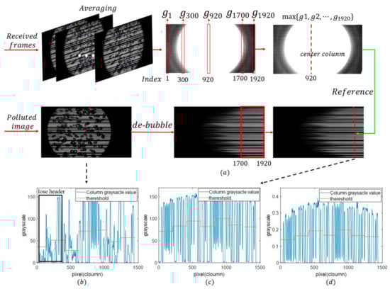
Figure 1.
(a) Diagram of de-bubble algorithm. (b) Raw column pixels with bubbles, (c) column pixels after de-bubbling, and (d) the column pixels after de-bubbling and gamma correction
Firstly, if the resolution of image frame is in order to determine the pixel value reference of the same bit, the column center of the light source needs to be found. A total of 100 received frames are averaged to form the average frame, which represents the grayscale distribution of the received light pattern. Each column of the average frame is summed to get , and the maximum value of is acquired. The index corresponding to the maximum value is the approximate column center index of the light source; we marked it as . Secondly, in the sorted image, all the elements in columns - are taken to as candidate values of . Next, each row of the sorted image is traversed to check the column subscript of the candidate elements in the original image, and the element with the closest index to as the element of (the red curve in Figure 1a) is found. This is equivalent to selecting pixels that bypass the bubble area on each row of the grayscale image to form a column matrix. Nevertheless, the complexity of the method based on sorting is much lower. Figure 1c shows the selected valid column matrix where the bubbles are removed. It can be clearly seen that the header information lost due to the bubble effect in Figure 1b is recovered, thus ensuring the reliability of subsequent decoding.
2.2. Sampling Scheme Based on Binary Fringe Correction (BFC)
In the decoding process of a rolling shutter effect (RSE)-based underwater optical camera communication (UOCC) system, conventional clock recovery (CR) based on a synchronization head is widely used. However, due to the exposure overlapping effect [19], the duration of the received synchronization header may not be an integer multiple of bit duration. Although the interpolation scheme was proposed in [23,24] to increase the effective sampling points for synchronization and demodulation, binary fringes whose length is not an integral multiple of the sampling interval will still be obtained after thresholding, which will lead to dislocation sampling, as shown in Figure 2.
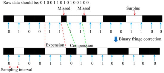
Figure 2.
Schematic diagram of sampling offset and the binary fringes correction (BFC) method.
To solve this situation, a binary fringe correction (BFC) method is proposed in this paper; the flow chart is shown in Figure 3. Firstly, linear interpolation is used to make the fringe width of one bit be odd and recorded as X. After thresholding, a binary sequence containing only 0 or 1 is obtained. Then, according to the statistics of the black and white stripes, the arrays and (containing the length elements of the black and white stripes, respectively), and the arrays and (containing the starting position elements of the black and white stripes, respectively) are obtained. One case is that the first element of is less than that of the corresponding position of , which means that the dark stripe will be recovered preferentially. Then fringe correction is executed, which is done by increasing the index “cursor” in the array . The next step is to check the length of the dark fringe. When the fringe length of the corresponding position of “cursor” or is less than , it is considered to be caused by noise that can be neglected, where is a rounding symbol (for example = 5, = 3). In this case, the next corresponding bright stripe will be restored. Otherwise, the fringe will be corrected based on the multiple of X and the recovery of dark and bright stripes is done alternately. For instance, if the number of pixel rows occupied by a bit is 9 after interpolation, a black stripe of length 7 will be corrected to 9, the next white stripe of length 38 will be corrected to 36, and so on.
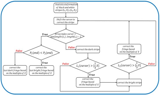
Figure 3.
Flow diagram of the proposed BFC method.
It is worth noting that the length of and will always differ by 1 due to the alternate appearance of dark and bright stripes. The loop will stop until the cursor moves to the end of the shorter one between and . Finally, for the longer array ( or ), we should correct the corresponding fringe again. In the other case, the operation is similar, but the bright stripe will be restored preferentially. What is more, in order to guarantee that each sampling can obtain the value exactly in the middle of the fringe, it is necessary to ensure that one bit occupies an odd number of pixel rows after interpolation.
3. Experimental Section
3.1. Methodology
The main objective of this paper was to test the performance of a rolling shutter effect (RSE)-based underwater optical camera communication (UOCC) system under the condition of bubble interference, and to verify the performance improvement of the proposed de-bubble algorithm and binary fringe correction (BFC) scheme. As was mentioned before, the existence of bubbles will make the gray level fluctuate significantly, and even directly cause the error decision. In a real bubbly UOCC link, air bubbles will be created in the water due to the breaking surface waves and rain, leading to a decrease in the signal–noise ratio (SNR). In this paper, MATLAB R2017a was used as the platform for data decoding. The proposed algorithms were proved by measuring the bit error rate (BER) of the system in different underwater environments.
3.2. Experimental Setup
The system model and decoding process of the RSE-based UOCC using a CMOS camera are shown in Figure 4. Our experimental setup was implemented in a transparent water tank with dimensions of 23 28 150 cm3. The water tank was three-fourths filled with tap water or saline water. At the transmitter side, the data packet was first constructed by a computer and loaded into the micro control unit (STM32). The structure of the UOCC data packet contained a 10-bit header and payload. Each packet was transmitted three times to mitigate the gap-time effect and guarantee each image frame captured by the mobile phone contained a complete data packet [14]. The non-return-to-zero (NRZ) on-off keying (OOK) format was utilized to modulate the data. The general-purpose input/output (GPIO) pin output high and low voltage, which corresponded to the data bits “1” and “0” respectively. Due to the restricted current drive of GPIO, a LED driver was placed after the STM32 to increase the current drive and control the brightness of the 9W white-light LED downlight with a color temperature of 6000 K. Therefore, the GPIO pin of STM32 was responsible for controlling the LED driver rather than directly driving the LED.
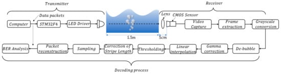
Figure 4.
Block diagram of the rolling shutter effect (RSE)-based underwater optical camera communication (UOCC) system for the experiment.
After a 1.5 m underwater and 5 cm air channel transmission, a plano-convex lens was adopted in front of a smartphone (Huawei P20 Pro with resolution of 1920 × 1080 (1080P) and frame rate of 60 fps) to condense the incoming light at the receiving side. The smartphone camera was employed in video capture mode with a manual configuration of the exposure compensation of –4 exposure value (EV), an international organization for standardization (ISO) value of 250, and the exposure time adjusted to 250 . The key hardware parameters are shown in Table 1.

Table 1.
Hardware parameters of the experiment.
Various underwater scenarios were demonstrated in this study. Since the breaking waves and rain are the main cause of upper ocean bubbles, we used clear tap water at normal temperature (25 °C) as the experimental environment in the first scenario. In the second scenario, in order to better simulate the real marine environment, we added sea salt to the tap water (25 °C) at a salinity of 30%. In the above two environments, a tunable air pump with a maximum outgassing volume of 3.5 L/min was employed to generate random air bubbles. The bubble density and the distance from the camera were taken into account to verify the effectiveness of the proposed algorithms. The density of random bubbles was set to be dense or sparse by changing the regulating valve of the air pump. In addition, we denoted the distance between the air pump and the camera with , which was set to 5 cm and 10 cm in different scenarios. Moreover, we also studied the case of the air pump moving continuously, including the transverse movement of the air pump (keeping and density unchanged) in Figure 5a and the longitudinal movement of the bubble (keeping the position in the image and the density unchanged) in Figure 5b. The specific setting parameters of different underwater environments are shown in Table 2.
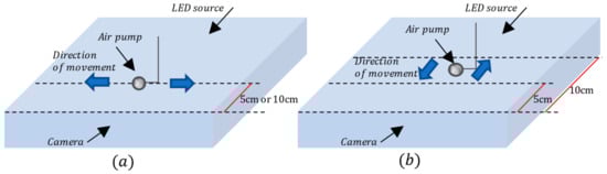
Figure 5.
Schematic diagram of the bubble movement (a) Transverse movement. (b) Longitudinal movement.
Table 2.
Underwater environmental parameters of the experiment.
In the demodulation part, firstly, the raw movie file captured by the mobile-phone CMOS image sensor was converted into grayscale format. Based on the analysis of the underwater channel attenuation under the bubbles and the rolling shutter effect (RSE) characteristics, a de-bubble algorithm was proposed to support robust UOCC transmission. A proper column matrix of grayscale values was selected from the grayscale image and linearly interpolated. The iterative threshold method [21] was employed. To mitigate the sampling point offset (SPO), we also proposed a novel sampling scheme based on binary fringe correction (BFC). When the sampling was completed, the header needed to be located in the image frame for packet reconstruction. After the above steps, the recovered data packet was examined for the bit error rate (BER) calculation so as to evaluate the transmission performance of the RES-based UOCC system. The experimental scene is illustrated in Figure 6.
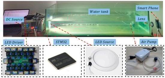
Figure 6.
Experimental scene.
3.3. Analysis of Bubble Effect on UOCC Link
3.3.1. Influence Analysis of Bubble Density on Different Data
Due to the different forms of received signals, the influence of bubbles on optical signals in a photo detector (PD)-based underwater wireless optical communication (UWOC) system and an RSE-based UOCC system was also different. We first investigated the effect of different bubble density on bits “1” and “0”. Figure 7a–c shows the influence of bubbles on sending data bit “1” in saline water. Figure 7a illustrates the received “1” sequence through a saline water link without bubbles. The received signal was approximately constant over a large period of time when it came to low-range and stable underwater links. When the optical signals went through a bubbly salty water link with different concentrations of air bubbles, as shown in Figure 7b,c, the appearance of bubbles led to serious fluctuations of light intensity. This was mainly due to the random distribution of bubbles through the propagation path, causing the light beams to randomly scatter in different directions and deviate from their original path. In addition, the fluctuation appeared more frequently with the increase of bubble density. Figure 7d–f illustrates the received signal “0” through a salty water link with and without bubbles. Apparently, the presence or absence of bubbles had no effect on the reception of bit “0” in this experiment. It should be noted that this was related to the modulation format. On-off keying (OOK) modulation was used in this study, which means that the “off” state of light denoted symbol “0”; hence, the camera captured dark streaks at a suitable international organization for standardization (ISO).
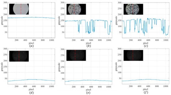
Figure 7.
Sending “1” through a salty water link without bubbles (a), with sparse bubbles (b), and with dense bubbles (c). Sending “0” through a salty water link without bubbles (d), with sparse bubbles (e), and with dense bubbles (f).
3.3.2. Influence Analysis of Different Bubble Size
Secondly, to investigate the effect of different air bubble sizes, we captured two cases from the images taken with the CMOS camera. One case was that the bubble size was larger than the duration of bit “1”, as shown in Figure 8a. Large bubbles obstruct the optical beam and cause a deep fade, which was reflected in the insert image as irregular shadow areas. These shadow pixels should not be selected for decoding, as it would lead to the misjudgment of “1” as “0”. Nevertheless, due to the distortion of the bubbles under the UOCC link, a transmission zone was formed at its center. In addition, owing to the rolling shutter effect (RSE) of CMOS, in each row of the image, it recorded the same data signal of the LED. Therefore, bit “1” could still be recovered correctly as long as the appropriate area was selected (such as M region in Figure 8a). Another situation was that the bright fringe was wider than the bubble size (Figure 8b). As is observed, the level of fading also decreased because the optical signal was less susceptible to serious obstruction so more light reached the image sensor. This means that more available areas could be used for decoding.
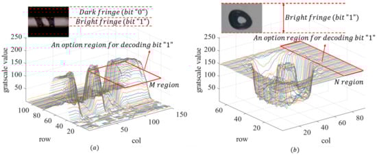
Figure 8.
The effect of different air bubble size: (a) Bubble size is larger than the duration of bit “1” and (b) bubble size is less than the duration of bit “1.”
3.3.3. State Analysis of Bubbles in Different ISOs
Furthermore, we also discussed the state of bubbles in different ISOs. We fixed the position of the air pump and kept the bubble density and unchanged (= 5). Four different ISOs (50, 250, 640, and 3200) were set to observe the effect of bubbles and stripes (as shown in Figure 9). Obviously, the bubbles did not disappear when the ISO was changed. Therefore, in this case, the ISO needed to be selected according to the quality of fringes rather than bubbles. We found that when the ISO was low, the camera’s sensitivity to light became weaker, resulting in serious blurring of bubbles and stripes. As the ISO increased, the camera sensed more light in the same exposure time, which led to a decrease in the contrast of dark and bright stripes in the image. After synthesizing the analysis and the discussion above, an ISO of 250 was selected to obtain the best image definition and contrast in this experiment.
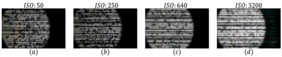
Figure 9.
Different imaging conditions in ISOs of (a) 50, (b) 250, (c) 640, and (d) 3200.
3.4. Effect and Efficiency Analysis of De-Bubble Algorithm
In order to verify the effectiveness of the proposed de-bubble algorithm, we tested the effect of bubble removal in four different bubble environments with a data rate of 7.2 Kbit/s, as shown in Figure 10. The results show that the proposed de-bubble algorithm based on sorting could effectively deal with bubbles in various situations, and the processing results were not affected by bubble densities, sizes, or distances. This is mainly because the multi-dimensional effects of bubbles on optical signals (such as reflection, refraction, scattering, and backscattering) can be reflected into one-dimensional pixels in the RSE-based UOCC system.
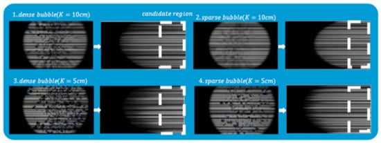
Figure 10.
Performance of the proposed method in different bubbly environments.
We also compared the proposed scheme with the traditional image inpainting algorithm based on the fast marching method (FMM) [27]. The basic idea of the traditional inpainting method is to get the mask of bubble region by maximum entropy segmentation [28], which represents the damaged area in the original image. Then the FMM algorithm is used to repair the image according to the mask so as to remove bubbles. The comparison between the FMM and our proposed de-bubble method is shown in Figure 11. Obviously, the maximum entropy segmentation cannot separate the correct mask for the fringe image with an especially complex background. In addition, the FMM algorithm needs to use the neighborhood pixels of masks, which will cause inter symbol interference (ISI) in the process of decoding.
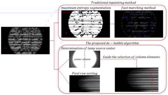
Figure 11.
Comparison between fast marching method (FMM) and our proposed de-bubble method.
Moreover, the processing latencies were evaluated. The computer used had an Intel i7 8565U processor @ 1.8 GHz with 8 GB random access memory (RAM). The processing times required for the FMM-based inpainting method and our proposed scheme were 11.63 s and 2.84 s. Apparently, the proposed de-bubble algorithm had lower computational complexity and higher efficiency and it was more suitable for underwater applications.
3.5. Comprehensive Performance Analysis of UOCC System
After grayscale conversation, de-bubbling and selection of column matrix, gamma correction, linear interpolation, thresholding, sampling adjustment, and recovering the data logic, the BER performances of RSE-based UOCC under different underwater environments (according to Table 2) could be evaluated. In this study, the number of pixel rows occupied by a bit was 15 after interpolation, so we corrected the fringes based on the multiple of 15. Payload bit lengths of 60 bits, 80 bits, 100 bits, 120 bits, and 140 bits were compared. The transmitted symbol rate was 10.8 kBaud (60 (data bits/frame) × 60 (frames/second) × 3 (repeat 3 times) = 10.8 kBaud), 14.4 kBaud, 18 kBaud, 21.6 kBaud, and 25.2 kBaud. The net data rates after the header and redundant packets removal can be calculated by the bit length in the payload per image frame times the frame rate. Hence, the corresponding transmitted data rate was 3.6 Kbit/s, 4.8 Kbit/s, 6 Kbit/s, 7.2 Kbit/s, and 8.4 Kbit/s.
3.5.1. Performance Analysis When the Air Pump Is Stationary
The BER performance in saline water under various settings (when the position of the air pump was fixed) is shown in Figure 12, where the red line indicates the use of traditional CR decoding. Since the amount of data sent from the transmitter (Tx) was limited to , it could be considered an error free transmission when the BER was . As observed, at the payload bit lengths of 60 bits and 80 bits, the BER performances of all the situations were error free when the proposed two methods were applied. As the payload bit length was increased, fewer pixel rows represented one logic bit. Hence, the bad BER performance was obtained in the case of dense bubbles and = 5, where is the distance between the air pump and the camera. We also found that when data rate and were fixed, the BER became poor with the increase in bubble density. Conversely, if the data rate and bubble densities remained unchanged, the decrease in led to the deterioration of the BER. It is worth pointing out that BER performances cannot satisfy the 7% forward error correction (FEC) limit without the proposed methods even at a low data rate of 3.6 Kbit/s. Experimental results show that the proposed schemes can significantly improve the BER performance and resist various bubble environments compared to the traditional CR scheme, whether the bubbles are sparse or dense.
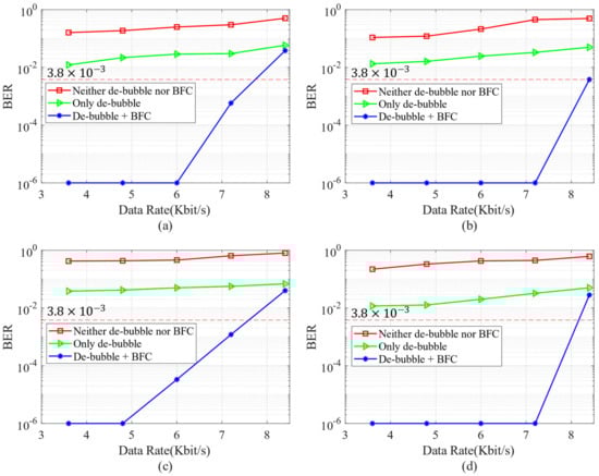
Figure 12.
Bit error rate (BER) performance between of the proposed methods with (a) dense bubbles (= 10 cm); (b) sparse bubble degradation (= 10 cm); (c) dense bubble degradation (= 5 cm), and (d) sparse bubbles (= 5 cm).
3.5.2. Performance Analysis When Air Pump Is Moving
Furthermore, the BER performance at various rates when the air pump moved and dense bubbles were generated is shown in Figure 13. Due to the movement of the bubbles, the focus of the camera changed occasionally and the BER fluctuated slightly. However, each frame could still be regarded as the situation when the air pump was fixed. It is obvious that the proposed de-bubble algorithm can significantly increase the transmission data rate and provide robust transmission even in a harsh underwater bubble situation.
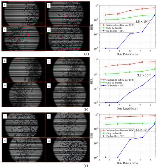
Figure 13.
BER performances in a dense bubble moving scene: (a) = 5 and the bubble source moves left and right in the image, (b) = 10 and the bubble source moves left and right in the image, (c) the air pump is located in the center of the image and varies from 5 to 10.
3.5.3. Performance Analysis under Different Water Environments
In order to investigate the impact of different water environments, we measured the BER under different bubble environments in 25 °C tap water and 25 °C saline water at various data rates, as shown in Table 3. As can be seen, the BER performance of the optical signal in tap water and saline water was almost the same. This is mainly due to the fact that there were no changes in the index of refraction due to salinity variations within the water tank. The optical properties were not affected when the optical signal was propagating through such a homogeneous optical channel.
Table 3.
BER under different bubble environments in tap water and saline water.
3.5.4. Comparison of Rate and Distance between Different Systems
Table 4 shows the comparison of the data rate and communication distance between the our proposed RES-based UOCC system and the GS-based UOCC or land-OCC systems proposed in other publications.
Table 4.
Comparison between different systems.
According to Table 4, our proposed scheme can achieve a faster data rate over a relatively long distance and has high robustness. We believe that this data rate may enough to send secure identification or authorization information for autonomous underwater vehicle (AUV) interconnection or send position information in an underwater navigation system.
4. Conclusions
In this paper, we proposed a de-bubble algorithm to combat bubble degradation. At the same time, a sampling method based on binary fringe correction (BFC) was proposed to mitigate sampling point offset. The results show that error-free transmission can be achieved at a data rate below 4.8 Kbit/s. In addition, under the 7% forward error correction (FEC) limit of , the data rate of 7.2 Kbit/s can be achieved by applying two proposed algorithms at the same time, which is 8.6 times higher than the baseline [5]. We believe that this data rate may be enough to send secure identification or authorization information for AUV interconnection or send position information in an underwater navigation system.
Author Contributions
Conceptualization: W.G.; methodology: Z.Z.; project administration, Z.Z. and W.G.; software: Z.Z.; data curation: Y.L. and W.X.; investigation: Y.L. and W.X.; supervision: S.W. and Z.C.; writing—original draft: Z.Z.; writing—review and editing: Z.Z. and W.G. All authors have read and agreed to the published version of the manuscript.
Funding
This research was funded by the Research and Development Program in Key Areas of Guangdong Province (2019B010116002), the National Undergraduate Innovation and Entrepreneurship Training Program (202010561020), and the Guangdong Science and Technology Project under grant 2017B010114001.
Conflicts of Interest
The authors declare no conflict of interest.
References
- Chitre, M.; Shahabudeen, S.; Freitag, L.; Stojanovic, M. Recent advances in underwater acoustic communications & networking. In Proceedings of the OCEANS, Quebec City, QC, Canada, 15–18 September 2008; pp. 1–10. [Google Scholar]
- Liu, W.; Xu, Z. Some practical constraints and solutions for optical camera communication. Philos. Trans. R. Soc. A Math. Phys. Eng. Sci. 2020, 378, 20190191. [Google Scholar] [CrossRef] [PubMed]
- Moreno, D.; Rufo, J.; Guerra, V.; Rabadan, J.; Perez-Jimenez, R. Effect of temperature on channel compensation in op-tical camera communication. Electronics 2021, 10, 262. [Google Scholar] [CrossRef]
- Akram, M.; Godaliyadda, R.; Ekanayake, P. Design and analysis of an optical camera communication system for un-derwater applications. IET Optoelectron. 2019, 14, 10–21. [Google Scholar] [CrossRef]
- Akram, M.; Aravinda, L.; Munaweera, M.; Godaliyadda, G.; Ekanayake, M. Camera based visible light communication system for underwater applications. In Proceedings of the 2017 IEEE International Conference on Industrial and Information Systems (ICIIS), Peradeniya, Sri Lanka, 15–16 December 2017; pp. 1–6. [Google Scholar]
- Chow, C.-W.; Chen, C.-Y.; Chen, S.-H. Enhancement of Signal Performance in LED Visible Light Communications Using Mobile Phone Camera. IEEE Photon. J. 2015, 7, 1–7. [Google Scholar] [CrossRef]
- Nguyen, T.; Hong, C.H.; Le, N.T.; Jang, Y.M. High-speed asynchronous Optical Camera Communication using LED and rolling shutter camera. In Proceedings of the 2015 Seventh International Conference on Ubiquitous and Future Networks, Sapporo, Japan, 7–10 July 2015; pp. 214–219. [Google Scholar]
- Kim, B.W.; Yoo, J.-H.; Jung, S.-Y. Design of Streaming Data Transmission Using Rolling Shutter Camera-Based Optical Camera Communications. Electronics 2020, 9, 1561. [Google Scholar] [CrossRef]
- Ji, P.; Tsai, H.-M.; Wang, C.; Liu, F. Vehicular Visible Light Communications with LED Taillight and Rolling Shutter Camera. In Proceedings of the 2014 IEEE 79th Vehicular Technology Conference (VTC Spring), Seoul, Korea, 18–21 May 2014; pp. 1–6. [Google Scholar]
- Liu, Y.; Liang, K.; Chen, H.-Y.; Wei, L.-Y.; Hsu, C.-W.; Chow, C.-W.; Yeh, C.-H. Light Encryption Scheme Using Light-Emitting Diode and Camera Image Sensor. IEEE Photon. J. 2016, 8, 1–7. [Google Scholar] [CrossRef]
- Chow, C.-W.; Liu, Y.-C.; Shiu, R.-J.; Yeh, C.-H. Adaptive Thresholding Scheme for Demodulation of Rolling-Shutter Images Obtained in CMOS Image Sensor Based Visible Light Communications. IEEE Photon. J. 2018, 10, 1–6. [Google Scholar] [CrossRef]
- Jamali, M.V.; Khorramshahi, P.; Tashakori, A.; Chizari, A.; Shahsavari, S.; AbdollahRamezani, S.; Salehi, J.A. Statis-tical distribution of intensity fluctuations for underwater wireless optical channels in the presence of air bubbles. In Proceedings of the 2016 Iran Workshop on Communication and Information Theory (IWCIT), Tehran, Iran, 3–4 May 2016; pp. 1–6. [Google Scholar]
- Davis, G.E. Scattering of Light by an Air Bubble in Water. J. Opt. Soc. Am. 1955, 45, 572–581. [Google Scholar] [CrossRef]
- Hagem, R.M.; Thiel, D.V.; O’Keefe, S.G.; Fickenscher, T. The effect of air bubbles on an underwater optical communica-tions system for wireless sensor network applications. Microw. Opt. Technol. Lett. 2012, 54, 729–732. [Google Scholar] [CrossRef]
- Zedini, E.; Oubei, H.M.; Kammoun, A.; Hamdi, M.; Ooi, B.S.; Alouini, M.-S. A New Simple Model for Underwater Wireless Optical Channels in the Presence of Air Bubbles. In Proceedings of the GLOBECOM 2017—2017 IEEE Global Communications Conference, Singapore, 4–8 December 2017; pp. 1–6. [Google Scholar]
- Chen, D.; Wang, J.; Li, S.; Xu, Z. Effects of air bubbles on underwater optical wireless communication [Invited]. Chin. Opt. Lett. 2019, 17, 100008. [Google Scholar] [CrossRef]
- Zhao, Y.; Wang, A.; Zhu, L.; Lv, W.; Xu, J.; Wang, J. Demonstration of underwater wireless optical communication using directly modulated green laser and different modes subjected to bubbles. In Proceedings of the 2017 Opto-Electronics and Communications Conference (OECC) and Photonics Global Conference (PGC), Singapore, 31 July–4 August 2017; pp. 1–2. [Google Scholar]
- Oubei, H.M.; Elafandy, R.T.; Park, K.-H.; Ng, T.K.; Alouini, M.-S.; Ooi, B.S. Performance evaluation of underwater wireless optical communications links in the presence of different air bubble populations. In Proceedings of the 2017 IEEE Photonics Conference (IPC), Orlando, FL, USA, 1–5 October 2017; Volume 9, pp. 441–448. [Google Scholar] [CrossRef]
- Chow, C.-W.; Chen, C.-Y.; Chen, S.-H. Visible light communication using mobile-phone camera with data rate higher than frame rate. Opt. Express 2015, 23, 26080–26085. [Google Scholar] [CrossRef] [PubMed]
- Zhang, Z.; Zhang, T.; Zhou, J.; Qiao, Y.; Yang, A.; Lu, Y. Performance Enhancement Scheme for Mobile-Phone Based VLC Using Moving Exponent Average Algorithm. IEEE Photon. J. 2017, 9, 1–7. [Google Scholar] [CrossRef]
- Liu, Y.; Chow, C.-W.; Liang, K.; Chen, H.-Y.; Hsu, C.-W.; Chen, C.-Y.; Chen, S.-H. Comparison of thresholding schemes for visible light communication using mobile-phone image sensor. Opt. Express 2016, 24, 1973–1978. [Google Scholar] [CrossRef] [PubMed]
- Shi, J.; He, J.; Deng, R.; Wei, Y.; Long, F.; Cheng, Y.; Chen, L. Multilevel modulation scheme using the overlapping of two light sources for visible light communication with mobile phone camera. Opt. Express 2017, 25, 15905. [Google Scholar] [CrossRef] [PubMed]
- Liang, K.; Chow, C.-W.; Liu, Y.; Yeh, C.-H. Thresholding schemes for visible light communications with CMOS camera using entropy-based algorithms. Opt. Express 2016, 24, 25641–25646. [Google Scholar] [CrossRef] [PubMed]
- Chen, C.-W.; Chow, C.-W.; Liu, Y.; Yeh, C.-H. Efficient demodulation scheme for rolling-shutter-patterning of CMOS image sensor based visible light communications. Opt. Express 2017, 25, 24362–24367. [Google Scholar] [CrossRef] [PubMed]
- Le, N.-T.; Nguyen, T.; Jang, Y.M. Frequency shift on-off keying for optical camera communication. In Proceedings of the 2014 Sixth International Conference on Ubiquitous and Future Networks (ICUFN), Shanghai, China, 8–11 July 2014; pp. 22–25. [Google Scholar]
- Rufo, J.; Delgado, F.; Quintana, C.; Perera, A.; Rabadan, J.; Perez-Jimenez, R. Visible light communication systems for optical video transmission. Microw. Opt. Technol. Lett. 2010, 52, 1572–1576. [Google Scholar] [CrossRef]
- Telea, A.A. An Image Inpainting Technique Based on the Fast Marching Method. J. Graph. Tools 2004, 9, 23–34. [Google Scholar] [CrossRef]
- Kapur, J.N.; Sahoo, P.K.; Wong, A.K. A new method for gray-level picture thresholding using the entropy of the histo-gram. Comput. Vis. Graph. Image Process. 1985, 29, 273–285. [Google Scholar] [CrossRef]
- Wang, W.C.; Chow, C.W.; Chen, C.W.; Hsieh, H.C.; Chen, Y.T. Beacon jointed packet reconstruction scheme for mo-bile-phone based visible light communications using rolling shutter. IEEE Photon. J. 2017, 9, 1–6. [Google Scholar]


Publisher’s Note: MDPI stays neutral with regard to jurisdictional claims in published maps and institutional affiliations. |
© 2021 by the authors. Licensee MDPI, Basel, Switzerland. This article is an open access article distributed under the terms and conditions of the Creative Commons Attribution (CC BY) license (https://creativecommons.org/licenses/by/4.0/).