Abstract
This research presents an easy to fabricate isotropic printed arc antenna element to be used for direction of arrival (DoA) arrays. The proposed antenna exhibits a total gain variation of 0.5 dB over the entire sphere for 40 MHz impedance bandwidth at 1 GHz, which is the best design isotropy reported in literature so far. In addition, the isotropic bandwidth of the antenna for total gain variation of ≤3 dB is 225 MHz with 86% efficiency. The isotropic wire antenna is first designed and simulated in Numerical Electromagnetic code (NEC). An equivalent printed antenna is then simulated in CST, where single (short circuited) stub is integrated with the antenna for input matching and the results of NEC simulations are verified. The planar antenna is then manufactured using FR4 substrate for measurements. Good agreement between the measured and simulated results is observed, however the total gain variation is increased to 2 dB for the fabricated antenna. This is because of the unavoidable field scattering from the antenna substrate, the feed cables, and the antenna testing platform.
1. Introduction
Isotropic antennas are capable of transmitting or receiving uniform power in all three dimensions. Such antennas are useful in applications where the relative position of the receive and the transmit antennas is uncertain or keeps changing. Radio Frequency Identification (RFID) systems, wireless endoscopy, energy harvesting, wireless Access Points (APs), Internet of Things (IoTs), and antennas for Satellites and drones are examples of such applications [1,2,3,4,5,6].
Isotropic antennas are also ideal elements in arrays that are designed for direction of arrival (DoA) estimation [7]. This is because using antennas with nulls in beam pattern can result in an array that is blind to signal sources in the direction of null. In addition, any gain variation in beam pattern of individual antenna element can cause a bias in DoA estimation when multiple signal sources are present [8].
Although an ideal isotropic antenna can be useful in a number of applications, it is known to be impossible to achieve [9]. As a result, the design of near isotropic antennas has remained a challenging problem with many different designs being proposed in the literature. Amongst the designs reported in the literature, the best design [10] achieves a simulated variation of 0.91 dB and measured variation of 1.95 dB in total gain. This antenna comprises of a three-dimensional structure having upper (radiator) and lower patch (ground) connected via a sidewall which is fed through a coaxial probe. A three-dimensional folded spherical wire antenna (SWA) proposed in [11] has reported a maximum simulated variation of 3 dB in total gain. Another three-dimensional (3D) antenna has a /4 monopole configuration, wrapped on a box [12], it achieved a design variation of 9.46 dB in total gain by generating equal orthogonal vector potentials at an operating frequency of 900 MHz. Circular arraying of unidirectional antennas [13] attains quasi-isotropy, but needs complex antenna construction and feeding network. The design in [5] exploits the fractional order radiating behavior of a circular cavity sector and achieves isotropy of 5.7 dB at an operating frequency of 2.45 GHz having a bandwidth of 0.1 GHz for a reflection coefficient of ≤−10 dB. Another approach [14] uses a band of frequencies in such a way that the nulls of one frequency are filled up by the maxima of the other with multiport antenna or by many antennas operating at different frequencies (independent feeds), such that they have different polarizations. The concept of combining magnetic and electric dipoles presented in [15] involves a complex feed network with four quadrature signals that were fed to four L-shaped monopoles to achieve quasi-isotropy of 5.75 dB. In [16], a combination of two slots and a monopole provides half-space quasi-isotropy due to large plane ground. A total gain variation of 3.8 dB is realized in all three principal planes [17] through the combination of a pair of printed 1.4 turn loops and printed dipole. The dielectric resonator antenna (DRA) that was proposed in [18] achieved a theoretical variation of 3 dB by combining magnetic dipole with small ground plane that also serves the purpose of electric dipole. In [19], the length of two curved dipoles is adjusted to obtain an isotropic radiation pattern that exhibits a simulated variation of ≤3.7 dB in total gain and an isotropic bandwidth of 80 MHz for a total gain variation of ≤6 dB. A 3D U-shaped slot antenna design is proposed in [20], which had total simulated gain variation of ≤3 dB, with 10 dB impedance bandwidth of 27 MHz. Designs of planar antennas for achieving quasi-isotropic radiation pattern have been proposed in [21,22]. Both of the designs try to combine electric and magnetic dipoles for achieving isotropy and have reported gain variations of 7.9 dB and 12 dB, respectively; [23] has proposed a 3D antenna structure for dual band isotropic pattern with gain variation as small as 0.9 dB at one of the operating frequencies; [24] proposes an SRR based structure printed on a flexible material to design a quasi-isotropic antenna with gain variation of 3 dB; while, [25] again uses a combination of electric and magnetic dipole to achieve isotropy where the achieved gain variation is 5.2 dB.
Continuing on the effort of previous researchers, this paper presents a two-dimensional (2D)-planar near-isotropic antenna. The presented design is proposed to be used in DoA estimation. The main highlights of the proposed design are as follows:
- The proposed design achieves an overall gain variation of ≤0.5 dB in the total gain which is amongst the best isotropic radiation pattern. The measured variation in total gain is almost same as in [10] i.e., ≤2 dB.
- The proposed design is low cost and simple enough to be constructed by printing it on a substrate.
Table 1 gives a comparison of the proposed antenna with some of the significant existing designs reported in the literature. It can be seen that the proposed antenna has minimum Gain variation. In comparison to previous designs, the antenna also has a simple, planar configuration.

Table 1.
A comparison of simulation performance of proposed antenna with simulation results of existing antenna designs.
Section 2 of the paper describes the methodology for the design of the proposed isotropic antenna, while Section 3 presents the simulated results of the antenna. Section 4 describes the transformation of planar wire antenna to planar printed antenna. Section 5 shows the measured results of fabricated antenna with comparison of simulated results, while Section 6 concludes the paper.
2. A Near Isotropic Planar Antenna
Design Methodology
The basic design of the proposed isotropic antenna follows the same concept, as presented in [15], which states that it is possible to achieve isotropy if electric and magnetic dipoles with equal magnitude of electric field over the spherical surface are combined. Therefore, two orthogonal polarizations E (component of electric dipole) and E (component of magnetic dipole) are required to obtain an equal magnitude of electric field over the spherical surface around the antenna, thereby resulting in isotropic radiation pattern. For a vertically placed dipole (current flowing along z-axis), polarization in the far-field is also in vertical direction i.e., E parallel to the direction of current. Therefore, in order to achieve isotropic pattern, an approximately equal magnitude of current is required in the orthogonal direction to produce E component. The magnitude and location of each current source is then to be adjusted in such a way that the nulls and the points of low antenna gain are filled up gradually and eventually result in an approximate isotropic pattern.
Theoretically, this can be achieved by placing various small dipoles at arbitrary locations with the same phase reference point, so that their combined radiation pattern achieve maximum isotropy. However, in theoretical implementation, each small dipole would require an independent feed, which is practically not possible in a single feed antenna.
The field of a short dipole segment with arbitrary location but with single phase reference point is given by Equation [26].
where is the radiation pattern of the dipole segment at an arbitrary location , is the incremental source constant, while is the radiation constant. is the intrinsic impedance, while is the excitation current at the feed gap.
At first, Equation (1) was implemented in MATLAB to obtain an initial idea of achievable isotropy. The design was started with three segments: a horizontal segment (along x-axis), a vertical segment (along z-axis), and a ramp shaped linear segment. The magnitude of the electric field of a particular polarization can then be increased or decreased by varying the length of the current segment that is oriented in that direction. Figure 1 shows the initial design of arbitrary shaped antenna and the result, where radiation patterns of three segments are presented independently.
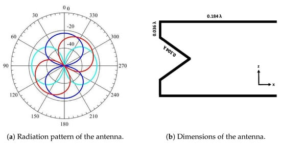
Figure 1.
Initial design simulated using MATLAB.
After arriving at initial design by use of Equation (1), a single antenna was modeled in NEC. However, the linear slope segment was replaced with a curved arc shaped segment for smoother as well as lesser gain variation. The geometrical parameters of the arc would control the current distribution and thus can be used to achieve isotropy [27]. Lengths of all three segments were fine tuned to further improve the achievable isotropy. The final design is shown in Figure 2. The red dot in the centre shows the feed point.
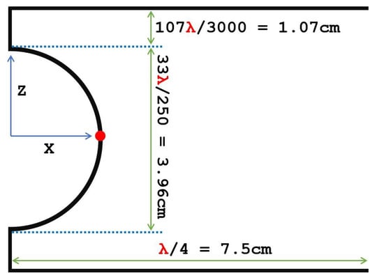
Figure 2.
Structure of proposed Isotropic antenna at 1 GHz.
It is shown in [27] that a full parametric sweep of arc radius from minimum to maximum value does not render equal magnitude of vertical (along z-axis) and horizontal (along x-axis) components and the former always remains dominant. Therefore, an equivalent contribution from both gain components was required to achieve lesser variation in total gain and better isotropy, which was achieved by using a larger horizontal segment.
A parametric study was carried out to study the effects on isotropy due to the variation in arc radius, vertical arm’s length, and horizontal arm’s length in order to find the optimum dimensions of the antenna. The most important parameter is arc radius, because it contributes in both horizontal and vertical gains, as already stated.
Figure 3 shows the 3D plots by only varying the horizontal arm’s length while keeping other parameters constant. The horizontal arm dimensions were reduced and increased and we found that as we go away from the optimum point, the total gain variation increases. Figure 3a shows a variation of 7.4 dB in total gain when the horizontal arm’s length is decreased by 27% of optimum dimensions. Similarly, Figure 3b shows the results when the dimensions are decreased by 13% of optimum length. Figure 3c,d show the results when the dimensions are increased by 13% and 27% that of optimum dimensions. As we go near the optimum length, the isotropy increases or the total gain variation reaches the lowest value.
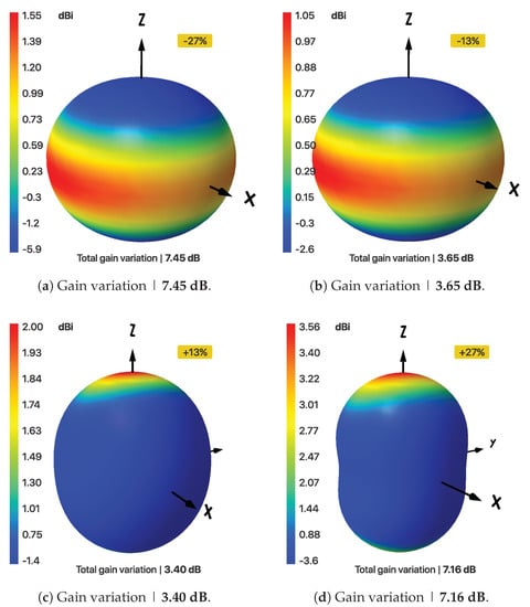
Figure 3.
Maximum variation in total gains, when length of horizontal arm is varied.
Similar results were found for the variations in dimensions of the vertical arm, while keeping the arc radius and horizontal arm’s length constant at the optimum point. As we go, go farther from the optimum length, either increasing side or decreasing side, the variation in total gain increases. Figure 4a,b show the 3D total gain plots when the vertical arm’s length is decreased by 80% and 50%, while Figure 4c,d show the results when it is increased by 93% and 187%, respectively.
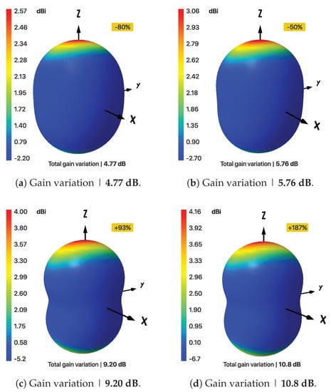
Figure 4.
Maximum variation in total gains, when length of vertical arm is varied.
Figure 5a shows the 3D plots when the arc radius is reduced by 50% that of our isotropic design, while Figure 5b shows 3D total gain variation when it is increased by 27%. Again, it can be seen that, either increasing or decreasing the arc radius, the isotropy decreases as we go farther from our optimum point. Figure 6 shows the magnitude and phase of the current in different segments of the wire. It can be seen that phase of the current in horizontal segments (x-direction) is opposite, leading zero contribution to radiation in y-direction.
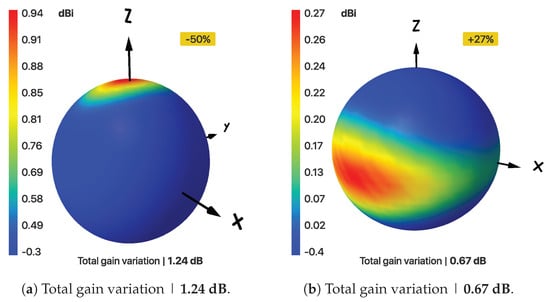
Figure 5.
Total gain variation for change in the arc radius.
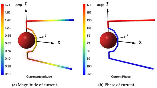
Figure 6.
Current variation in proposed antenna.
3. Simulation Results
3.1. Isotropic Wire Antenna
All of the simulation shown in this section were carried out in Numerical Electromagnetics Code (NEC). Figure 7 shows the input impedance and SWR values vs. frequency of proposed antenna. The reactive part of the input impedance 81.5 + 399 j at the operating frequency is compensated by loading the antenna feed point serially with a capacitor (C = 4 × 10⁻¹³ F). Figure 8 shows the input impedance and Voltage Standing Wave Ratio (VSWR) graphs after applying a compensation at the input. A purely resistive input impedance of 81 of the antenna can be seen and it matches well with a 75 coaxial cable resulting in a VSWR of 1.08. For the VSWR parameter to be ≤2, the antenna exhibits an impedance bandwidth of 40 MHz.
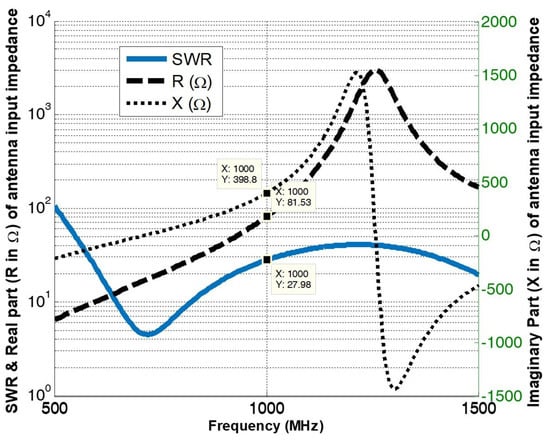
Figure 7.
Input impedance and the Voltage Standing Wave Ratio (VSWR) of the non-compensated antenna.
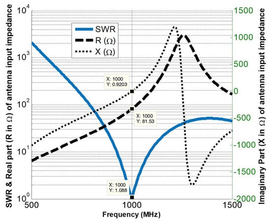
Figure 8.
Input impedance and the VSWR of the antenna after compensation.
The 3D patterns of arc antenna’s vertical, horizontal and total gains are shown in Figure 9 and Figure 10, respectively.
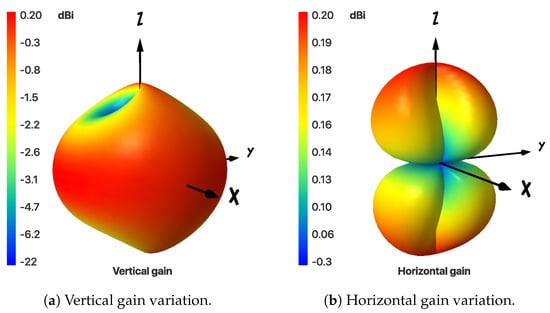
Figure 9.
3D radiation patterns of Vertical and horizontal gains of the arc antenna.
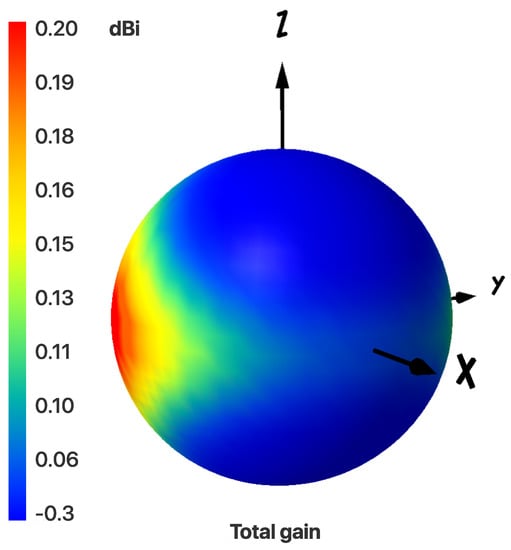
Figure 10.
Three-dimensional (3D) radiation pattern of the arc antenna’s total gain. Maximum variation is | 0.5 dB.
Figure 9 demonstrates that the horizontal and vertical gains have maxima of 0.2 dB, whereas their nulls are −16 dB and −120 dB, respectively. The addition of these two radiation patterns results in a near spherical pattern. This is due to the fact that maximas of both horizontal and vertical gains complement each other, resulting in maximum gain variation of 0.5 dB over the entire sphere, as shown in Figure 10. The two-dimensional (2D)-elevation plots of total gain with a 100 step and at different angles were analyzed and three representative plots are shown in Figure 11. These plots suggest that the total gain is nearly independent of , since, for the total gain, the maximum difference in any elevation plane is less than or equal to 0.5 dB.
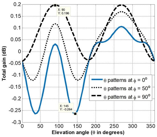
Figure 11.
Total gain vs elevation angle () at different azimuth angles .
Similarly, the azimuth plots of total gain with a 100 step and at different elevation angles were analyzed, and three representative plots are shown in Figure 12. Although the variation in total gain is slightly different for different elevation angles, the maximum gain variation in elevation plane for any angle is again ≤0.5 dB.
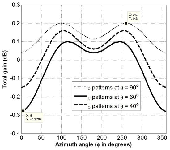
Figure 12.
Total gain vs azimuth angle () at different elevation angles .
3.2. Isotropic Bandwidth
The isotropic bandwidth of the antenna can be defined as the band of frequencies, for which the gain variation remains ≤3 dB. The proposed antenna was simulated for total gain variation vs frequency. Figure 13 shows the obtained results, and it can be observed that, at the optimal frequency of 1 GHz, the total gain variation is minimum (0.5 dB), while it increases almost symmetrically on both sides. The 3 dB isotropic bandwidth of the antenna is 225 MHz i.e., 22.5% (885 MHz–1110 MHz).
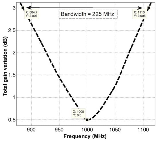
Figure 13.
Total gain variation vs frequency of the proposed antenna.
The azimuth and elevation gain plots at f1 = 885 MHz and f2 = 1110 MHz are shown in Figure 14 and Figure 15, respectively. It can be seen in Figure 14 that the maximum gain for f1 (885 MHz) frequency is 0.9 dB, while the minimum gain is −2.08 dB, which gives an overall difference in total gain of 3.07 dB. Similarly, the plots for f2 (1110 MHz) are shown in Figure 15, which, again, shows that the overall difference in total gain is close to 3 dB. It is to be noticed that the gain plots shown in Figure 14 and Figure 15 are complementary to each other.
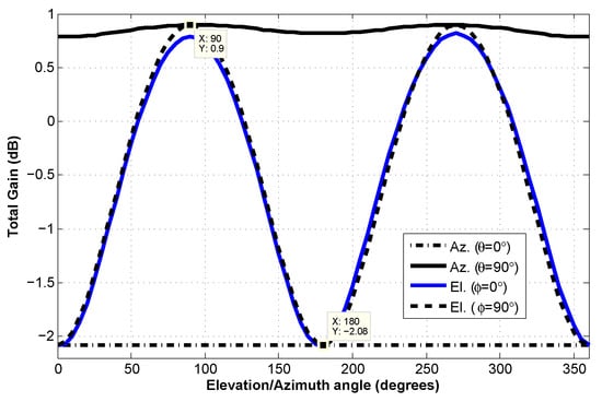
Figure 14.
Azimuth and elevation total gain plots at | f = 885 MHz.
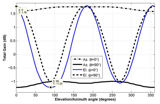
Figure 15.
Azimuth and elevation total gain plots at | f = 1110 MHz.
4. Transition from Wire Antenna to Planar Antenna
Although the wire antenna configuration is good enough for fabrication and measurements, an equivalent printed planar arc antenna would be a better option because of two reasons. Firstly, the input reactance of the wire antenna, although, can be easily compensated by putting a lumped component in series with the feed port in a simulation environment, yet it is cumbersome to achieve the same practically. Secondly the dimensions of the antenna structure should be precise to achieve maximum isotropy in measurements. Therefore, an equivalent printed planar arc antenna with the same electrical dimensions was simulated in CST to verify the performance. This was again done in two steps: a printed antenna with both dipole legs on the same side of the substrate was simulated first. Following the same technique of impedance matching proposed in Section 2, a capacitor in series is attached to the input port. The line thickness is kept at 1 mm. The design is simulated using FR4 substrate (ϵr = 4.4, h = 1.6 mm). Figure 16 presents the simulation layout of port fed printed antenna, while a 3D gain plot of the same is shown in Figure 17. It can be seen that, by adding the substrate, the total gain variation has increased from ≤0.5 dB to ≤0.8 dB.
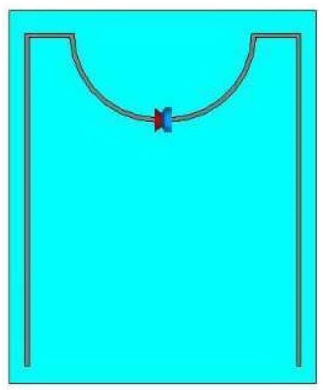
Figure 16.
Simulation layout of port fed printed antenna.
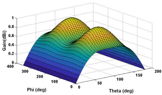
Figure 17.
3D Gain of port fed printed antenna.
Similarly, Figure 18 presents the simulation layout of the transmission line fed printed antenna, where it can be seen that two legs of the dipole printed on the top and bottom surfaces of the substrate are fed with a microstrip transmission line with integrated stub that compensates the reactive part of the input impedance of the antenna. The width of dipole legs is increased from 1 mm to 3 mm in order to match it with that of the 50 ohms transmission line.
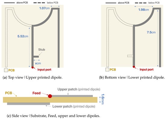
Figure 18.
Simulation layout of microstrip fed printed antenna.
Figure 19 also shows the current distribution of the printed antenna, and it can be seen that the current at the middle point of curved segment is maximum which almost entirely contributes to the horizontally polarized field. At the end of the arc, it becomes lower. Again, the small segment (z-direction) has a high current density and while the long arm (x-direction) has significantly low current density. Collectively though physically the antenna has a greater vertical length than horizontal and, therefore, is able to balance the power of vertical and horizontal polarizations providing isotropy.
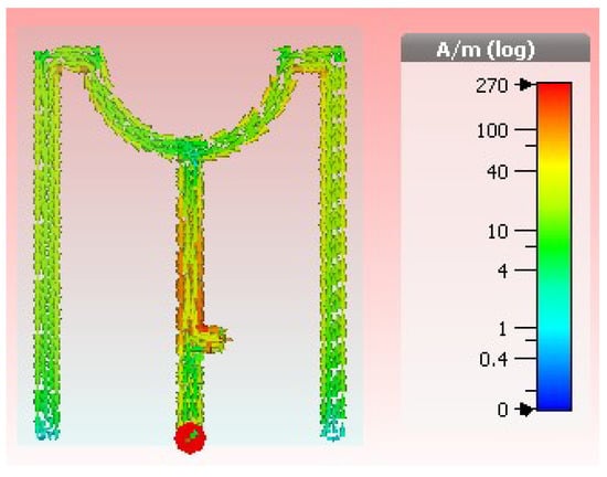
Figure 19.
Current distribution for the center frequency.
The 3D gain plot of the final printed design is shown in Figure 20, showing that the overall gain variation has now increased to ≤0.9 dB.
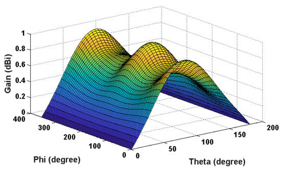
Figure 20.
3D Gain of microstrip fed printed antenna.
5. Antenna Fabrication & Measurements
The printed isotropic antenna was then fabricated using FR4 substrate (ϵr = 4.4, h = 1.6 mm) The measurements of the printed antenna were performed in the anechoic chamber and the results were compared for the centre frequency. Figure 21 shows the fabricated antenna, where antenna can be seen mounted on the measurement platform within the chamber. Antenna reflection coefficient was measured using E5071C, VNA while radiation pattern measurement was done using MI Technology (MI-3000) system. A comparison of measured and simulated results is presented in Figure 22 and Figure 23. It can be seen from Figure 22 that the simulated and measured return loss results are in good agreement, except for slight frequency shift. Various measurements of radiation pattern in different elevation planes were taken except at angles, where it was not possible because of the feed cable and the mounting arrangement and the one with maximum variation was selected for comparison. The measured radiation pattern is compared in Figure 23. The pattern is measured in azimuth plane. It can be seen that the overall difference in total gain (for measured results) came out to be 2 dB. Further difference in the simulated and measured, as shown in Figure 23, can be attributed to the field scattering that occurs due to nearby connector, cables, and the antenna platform within the chamber. Although the ease of fabrication and integration of this antenna makes it very attractive for portable equipment and devices, its proximity would affect the pattern and gain values.
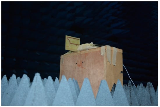
Figure 21.
Fabricated antenna in anechoic chamber.
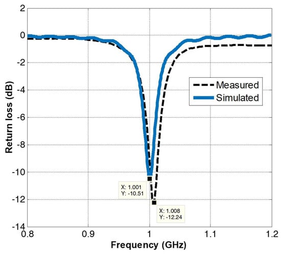
Figure 22.
Comparison of simulated and measured return loss of the printed isotropic arc antenna.
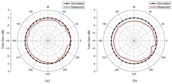
Figure 23.
Comparison of the simulated and measured gain pattern of the printed isotropic arc antenna (a) xy plane and (b) xz plane.
Table 2 shows the comparison of measured variation in total gain of the proposed antenna with those of the designs that were reported in literature, and it can be observed that the proposed design matches the performance of previously reported designs.
Table 2.
Comparison of maximum gain variation of fabricated proposed antenna with existing antennas. The bold text refers to design of this research.
Table 2 shows that the total measured variation in proposed antenna gain is almost the same as that of the antenna design proposed in [10]. However, amongst all of the isotropic designs reported in the literature, our proposed antenna has the lowest design (simulated) total gain variation. Furthermore, the impedance bandwidth of [10] is only 15 MHz (0.61%), while the impedance bandwidth of the proposed antenna is 40 MHz (4%).
6. Conclusions
The paper has presented the design of a near isotropic printed arc antenna. The presented design offers best simulated isotropic performance i.e., maximum variation in total gain of ≤0.5 dB, which is best amongst all of the isotropic antennas reported in literature so far; however, the total measured variation is ≤2 dB. The antenna offers 4% (40 MHz) bandwidth, where VSWR remains less than 2 dB, while 23.5% bandwidth where the total gain variation remains ≤3 dB. The results show that the measurements are in good agreement with that of the simulated results. Owing to its simple geometry, the microstrip antenna can easily be fabricated on a microwave substrate and integrated with RF circuits.
Author Contributions
Conceptualization, H.T.A. and S.A.; methodology, M.A.; software, S.A. and M.M.; validation, M.M., M.A. and A.R.M.; writing—original draft preparation, H.A., S.A.; writing—review and editing, M.M. and A.R.M.; supervision, M.A.; project administration, M.Y.; funding acquisition, M.Y. All authors have read and agreed to the published version of the manuscript.
Funding
Taif University Researchers Supporting Project number (TURSP-2020/293), Taif University, Taif, Saudi Arabia.
Acknowledgments
The current research is supported by Taif University Researchers Supporting Project number (TURSP-2020/293), Taif University, Taif, Saudi Arabia.
Conflicts of Interest
The authors declare no conflict of interest.
Abbreviations
The following abbreviations are used in this manuscript:
| RFID | Radio Frequency Identification |
| AP | Access Point |
| IoT | Internet of Things |
| DoA | Direction of Arrival |
| NEC | Numerical Electromagnetics Code |
| VSWR | Voltage Standing Wave Ratio |
References
- Pazin, L.; Dyskin, A.; Leviatan, Y. Quasi-Isotropic X-Band Inverted-F Antenna for Active RFID Tags. IEEE Antennas Wirel. Propag. Lett. 2008, 8, 27–29. [Google Scholar] [CrossRef]
- Cho, C.; Choo, H.; Park, I. Printed symmetric inverted-F antenna with a quasi-isotropic radiation pattern. Microw. Opt. Technol. Lett. 2008, 50, 927–930. [Google Scholar] [CrossRef]
- Xing, B.; Zhang, Y.; Zou, H.; Liu, Z. A Conformal Quasi-Isotropic Dielectric Resonator Antenna for Wireless Capsule Endoscope Application. Prog. Electromagn. Res. M 2021, 99, 211–221. [Google Scholar] [CrossRef]
- Georgiou, O.; Wang, S.; Bocus, M.Z.; Dettmann, C.P.; Coon, J.P. Directional antennas improve the link connectivity of interference limited ad hoc networks. In Proceedings of the IEEE 26th Annual International Symposium on Personal, Indoor, and Mobile Radio Communications, Hong Kong, China, 30 August–2 September 2015; pp. 1311–1316. [Google Scholar]
- Li, Q.; Lu, W.J.; Wang, S.G.; Zhu, L. Planar Quasi-Isotropic Magnetic Dipole Antenna Using Fractional-Order Circular Sector Cavity Resonant Mode. IEEE Access 2017, 5, 8515–8525. [Google Scholar] [CrossRef]
- Darwish, S.G.M.; Hussein, K.F.A.; Mansour, H.A. Circularly polarized crossed-dipole turnstile antenna for satellites. In Proceedings of the 21st National Radio Science Conference, Cairo, Egypt, 6–18 March 2004. [Google Scholar]
- Sanudin, R.; Noordin, N.H.; El-Rayis, A.O.; Haridas, N.; Erdogan, A.T.; Arslan, T. Analysis of DOA estimation for directional and isotropic antenna arrays. In Proceedings of the Loughborough Antennas & Propagation Conference, Loughborough, UK, 14–15 November 2011. [Google Scholar]
- Cheng, Z.; Guo, J.; Fan, X.; Ma, D. Effect of Power Difference of Two Signal Sources on Resolving Performance of MUSIC Algorithm. J. Electron. Inf. Technol. 2011, 30, 1088–1091. [Google Scholar] [CrossRef]
- Mathis, H. A short proof that an isotropic antenna is impossible. Proc. IRE 1951, 39, 970. [Google Scholar]
- Pan, Y.; Zheng, S. A Compact Quasi-Isotropic Shorted Patch Antenna. IEEE Access 2017, 5, 2771–2778. [Google Scholar] [CrossRef]
- Mehdipour, A.; Aliakbarian, H.; Rashed-Mohassel, J. A Novel Electrically Small Spherical Wire Antenna With Almost Isotropic Radiation Pattern. IEEE Antennas Wirel. Propag. Lett. 2008, 7, 396–399. [Google Scholar] [CrossRef]
- Su, Z.; Ghaffar, F.A.; Farooqui, M.F.; Bilal, R.M.; Shamim, A. Design methodology of single-feed compact near-isotropic antenna design. In Proceedings of the 11th European Conference on Antennas and Propagation, Paris, France, 19–24 March 2017. [Google Scholar]
- Zhang, Z.; Gao, X.; Chen, W.; Feng, Z.; Iskander, M.F. Study of conformal switchable antenna system on cylindrical surface for isotropic coverage. IEEE Trans. Antennas Propag. 2011, 59, 773–776. [Google Scholar] [CrossRef]
- Deschamps, G.; Dyson, J.; Mast, P. Two-port isotropic radiator for unpolarized waves. IEEE Trans. Antennas Propag. 1969, 6, 809–810. [Google Scholar] [CrossRef]
- Deng, C.; Li, Y.; Zhang, Z.; Feng, Z. A wideband isotropic radiated planar antenna using sequential rotated L-shaped monopoles. IEEE Trans. Antennas Propag. 2014, 62, 1461–1464. [Google Scholar] [CrossRef]
- Long, S.A. A combination of linear and aperture antennas for Quasi-Isotropic coverage. IEEE Trans. Antennas Propag. 1975, 75, 572–576. [Google Scholar] [CrossRef]
- Xu, X.; Huang, H.C.; Wang, Y.E. Isotropic radiation from an electrically small loop-loaded printed dipole. In Proceedings of the IEEE International Workshop on Antenna Technology, Santa Monica, CA, USA, 2–4 March 2009; pp. 1–4. [Google Scholar]
- Pan, Y.M.; Leung, K.W.; Lu, K. Compact quasi-isotropic dielectric resonator antenna with small ground plane. IEEE Trans. Antennas Propag. 2014, 62, 577–585. [Google Scholar] [CrossRef]
- Pan, G.; Li, Y.; Zhang, Z.; Feng, Z. Isotropic Radiation From a Compact Planar Antenna Using Two Crossed Dipoles. IEEE Antennas Wirel. Propag. Lett. 2012, 11, 1338–1341. [Google Scholar]
- Deng, C.; Li, Y.; Zhang, Z.; Feng, Z. Design of a Three-dimensional Folded Slot Antenna with Quasi-Isotropic Radiation Pattern. In Proceedings of the IEEE International Symposium on Antennas and Propagation, USNC/URSI National Radio Science Meeting, Vancouver, BC, Canada, 19–25 July 2015; pp. 588–589. [Google Scholar]
- Hu, P.F.; Pan, Y.M.; Zhang, X.Y.; Hu, B.J. A Compact Quasi-Isotropic Dielectric Resonator Antenna With Filtering Response. IEEE Trans. Antennas Propag. 2019, 67, 1294–1299. [Google Scholar] [CrossRef]
- Shah, S.I.H.; Tentzeris, M.M.; Lim, S. Planar quasi-isotropic antenna for drone communication. Microw. Opt. Technol. Lett. 2018, 60, 1290–1295. [Google Scholar] [CrossRef]
- Su, Z.; Klionovski, K.; Bilal, R.M.; Shamim, A. A Dual Band Additively Manufactured 3-D Antenna on Package With Near-Isotropic Radiation Pattern. IEEE Trans. Antennas Propag. 2018, 66, 3295–3305. [Google Scholar] [CrossRef]
- Wang, Y.; Tang, M.; Chen, S.; Li, L.; Li, D.; Hu, K.; Li, M. Design of Low-Cost, Flexible, Uniplanar, Electrically Small, Quasi-Isotropic Antenna. IEEE Antennas Wirel. Propag. Lett. 2019, 18, 1646–1650. [Google Scholar] [CrossRef]
- Radha, S.M.; Jung, M.; Park, P.; Yoon, I.J. Design of an Electrically Small, Planar Quasi-Isotropic Antenna for Enhancement of Wireless Link Reliability under NLOS Channels. Appl. Sci. 2020, 10, 6204. [Google Scholar] [CrossRef]
- Kildal, P.S. Foundations of Antenna Engineering: A Unified Approach for Line-of-Sight and Multipath; Artech House: Norwood, MA, USA, 2015. [Google Scholar]
- Amin, S.; Amin, M.; Ahmad, M.B.; Shah, A.A.; Abbasi, M.I. Extended Arc Antenna for Near Isotropic Radiation Pattern. In Proceedings of the IEEE Asia-Pacific Microwave Conference, Kuala Lumpur, Malaysia, 13–16 November 2017. [Google Scholar]


Publisher’s Note: MDPI stays neutral with regard to jurisdictional claims in published maps and institutional affiliations. |
© 2021 by the authors. Licensee MDPI, Basel, Switzerland. This article is an open access article distributed under the terms and conditions of the Creative Commons Attribution (CC BY) license (http://creativecommons.org/licenses/by/4.0/).