Abstract
Position information is very important tactical information in large-scale joint military operations. Positioning with datalink time of arrival (TOA) measurements is a primary choice when a global navigation satellite system (GNSS) is not available, datalink members are randomly distributed, only estimates with measurements between navigation sources and positioning users may lead to a unsatisfactory accuracy, and positioning geometry of altitude is poor. A time division multiple address (TDMA) datalink cooperative navigation algorithm based on INS/JTIDS/BA is presented in this paper. The proposed algorithm is used to revise the errors of the inertial navigation system (INS), clock bias is calibrated via round-trip timing (RTT), and altitude is located with height filter. The TDMA datalink cooperative navigation algorithm estimate errors are stated with general navigation measurements, cooperative navigation measurements, and predicted states. Weighted horizontal geometric dilution of precision (WHDOP) of the proposed algorithm and the effect of the cooperative measurements on positioning accuracy is analyzed in theory. We simulate a joint tactical information distribution system (JTIDS) network with multiple members to evaluate the performance of the proposed algorithm. The simulation results show that compared to an extended Kalman filter (EKF) that processes TOA measurements sequentially and a TDMA datalink navigation algorithm without cooperative measurements, the TDMA datalink cooperative navigation algorithm performs better.
1. Introduction
In large-scale joint military operations, datalink members can be commanded and controlled as a unified whole with position information, and position information is crucial to combat operation. At present, positions of network members can be obtained through absolute navigation methods like GNSS or long-range navigation (LORAN) systems [1,2]. However, GNSS is vulnerable to jamming, which will affect the accuracy of localization [3]. LORAN is also easily affected by noise and cross-rate interference [4]. A joint tactical information distribution system (JTIDS) can provide advantages like high transmission power and high anti-jamming capability [5]. Most of all, JTIDS can share location information between network members, and JTIDS users can extract TOA information; therefore, when GNSS or LORAN is jammed, the JTIDS network is a primary choice [6].
However, JTIDS has some disadvantages when positioning. First, JTIDS members are randomly distributed in the horizontal plane, and an uneven distribution of members may result in unevenness in the distribution of network members’ horizontal dilution of precision (HDOP) [7]. Members with poor HDOP of the network have low precision of latitude and longitude. Second, coverage of a large effective zone of the JTIDS network is about 500 km radius, but the height of network members is much smaller than the effective radius, and the distribution range of JTIDS members in the horizontal plane is much larger than the vertical difference, which result in a poor vertical dilution of precision (VDOP) and low estimate accuracy of members’ vertical ranges. In the general navigation algorithm of TDMA datalinks, joint units (JUs) process information of navigation sources and TOA measurements with a Kalman filter (KF) based on sequential processing, which can process TOA measurements sequentially and timely in the TDMA system, but the positioning performance is dissatisfactory when positioning geometry is poor [8,9,10]. To enhance the stability and accuracy of positioning, an integrated navigation method based on INS and datalink information was presented in [11,12], but they did not propose a good method to improve vertical accuracy. Therefore, a more practical positioning method of TDMA datalinks, such as JTIDS, is urgently needed.
To improve the altitude observation accuracy effectively, many scholars choose to add measurements of sensors, such as a barometer altimeter (BA), in the vertical direction. Authors in [13] proposed methods of loosely-coupled and tightly-coupled schemes with barometer information to improve location accuracy of a low cost INS/GNSS system under a harsh GNSS-degraded environment. To improve height accuracy of flight, authors in [14] investigated the combination of data from GNSS, radar, and barometer sensors. With pseudo-range, Doppler information, and MEMS barometric information, authors in [15] proposed a method of positioning with two satellites. Authors in [16] presented a state estimation technique by fusing measurements of long-range stereo visual odometry, a global positioning system (GPS), and barometric and inertial measurement units, and they improved positioning performance for the aggressive intermittent GPS and high-altitude micro-aerial vehicle (MAV) flight environment.
To improve positioning accuracy of network positioning users, the method of cooperative navigation was proposed by many scholars. Cooperative navigation has received extensive interest from the research field, like wireless sensor networks, mobile networks, and unmanned aerial vehicles (UAVs) [17,18,19]. Currently existing approaches for cooperative navigation are factor graphs and sum-product algorithms [20], semidefinite programming [21], particle filters [22], Kalman filters [23], and so on. In the cooperative navigation method, positioning users help each other to determine their locations. Compared to single positioning users, a group of cooperative positioning users may provide many navigational benefits, such as tolerance against individual user or sensor failures, distribution of sensors across a larger spatial area, and shared observations [24]. Cooperative navigation increases localization performance in terms of both accuracy and coverage [25]. Cooperative navigation is always used to improve positioning accuracy of network members in defective positioning environments. In GNSS-denied environments, authors in [24] addressed the cooperative localization approach for a small group of unmanned aerial vehicles (UAVs), and the proposed approach estimated each UAV’s relative position inside the group using ranging measurements and estimating global positioning magnetic anomaly measurements. A cooperative localization algorithm with TOA and received signal strength measurements was proposed in [26], and the proposed cooperative localization algorithm significantly improved the localization accuracy of mobile nodes that could not directly connect to a sufficient number of anchor nodes in a wireless sensor network. Authors in [27] investigated the operational framework for cooperative localization of UAVs using GNSS, microelectromechanical systems, INS, and ultra-wide-band (UWB) sensors to improve accuracy in regions that lack GNSS, and they provided a comparison of distributed and centralized architectures and proved that centralized architecture generally provides higher localization accuracy compared with the distributed architecture. An incentive mechanism for cooperative localization was proposed in [28] to improve the localization accuracy of wireless network nodes in harsh environments due to poor coverage or signal blockage. A hybrid cooperative positioning method based on GNSS, network anchors, and cooperative measurements was proposed in [29], and the proposed method improved localization accuracy of network agents with cooperative measurements between them.
In order to improve JTIDS network users’ accuracy of the horizontal plane and vertical direction, the TDMA datalink cooperative navigation method based on INS/JTIDS/BA is proposed. In the proposed method, an estimator is decomposed into altitude and horizontal planes. In the vertical direction, a height filter based on a barometric altimeter (BA) is used to correct altitude errors of the inertial navigation system (INS) independently. In the horizontal plane, the TDMA datalink cooperative navigation algorithm uses general navigation measurements, cooperative navigation measurements, and predicted states to estimate latitude and longitude errors of INS.
The rest of this paper is organized as follows: The second section overviews the basic principles of JTIDS navigation and introduces TDMA datalink cooperative navigation method of JTIDS. The third section introduces the integration architecture of the TDMA datalink cooperative navigation algorithm based on INS/JTIDS/BA and presents the RTT filter and altitude filter, and then explains the division method of estimate time slice and navigation slots, measurements, and WLS estimator of the proposed algorithm in detail. In the fourth section, the WHDOP of the TDMA datalink cooperative navigation algorithm and the effect of cooperative measurements on estimate errors are analyzed. In the fifth section, a simulation study is conducted to analyze and evaluate the proposed algorithm. The sixth section concludes the paper.
2. Principles of JTIDS Navigation and TDMA Datalink Cooperative Navigation Method of JTIDS
JTIDS is a synchronous, time division multiple access, spread spectrum communication system. As illustrated in Figure 1, members of JTIDS operate with different roles. The navigation controller (NC) establishes the relative coordinates. One user of the network runs time reference (TR), and other users will synchronize with TR directly or indirectly. Primary users (PUs) are permitted to synchronize with RTT protocol, and secondary users (SUs) are permitted to perform clock synchronization and navigation passively. Terminals with high absolute position accuracy are designated as position references (PRs) [6].
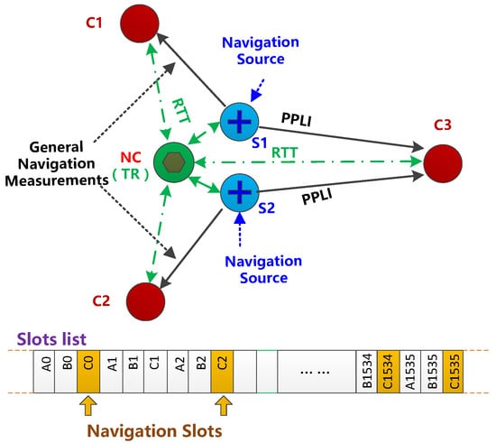
Figure 1.
JTIDS navigation network architecture.
2.1. Principles of JTIDS Navigation
Some slots of JTIDS are selected as navigation slots to transmit precise participant location and identification (PPLI) messages. PRs and terminals with high accuracy positions can transmit PPLI messages in their navigation slots as navigation sources. The structure of JTIDS messages is illustrated in Figure 2. The information of PPLI messages contains source terminal positions and speed, as well as position quality and time quality. Positioning users can extract general TOA navigation information from the synchronization header of the PPLI message and obtain position information of source terminals, and then estimate positions with these pieces of information [30].
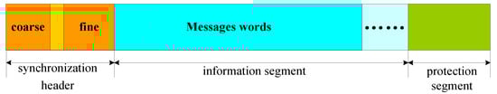
Figure 2.
JTIDS message structure.
In the general JTIDS navigation method, estimators of users process information and estimate distributed positions, and users only use PPLI messages transmitted from the navigation sources with higher accuracy.
2.2. TDMA Datalink Cooperative Navigation Method of JTIDS
In JTIDS network positioning, users and navigation sources are randomly distributed in the horizontal plane, and the geometrical distribution of navigation sources may not meet the requirements of each positioning user; therefore, more measurements are needed. However, the number of navigation sources is fixed within a short period time, so we take advantage of measurements between positioning users to improve their positioning accuracy; moreover, the height filter with measurements of BA is designed to estimate the heights of users.
In the TDMA datalink cooperative navigation method, several positioning users estimate their state together as a whole, and one centralized estimator is used to process positioning users’ information and estimate their latitude and longitude errors of INS together. We call these positioning users cooperative members.
As shown in Figure 3, in order to distinguish measurements used in the horizontal plane estimator, we define the measurements transmitted between the datalink navigation sources. Cooperative members are general navigation measurements, and measurements transmitted between cooperative members are cooperative navigation measurements.
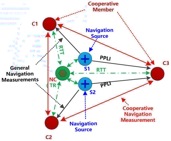
Figure 3.
Cooperative navigation method.
In the TDMA datalink cooperative navigation method, latitude and longitude errors of all cooperative members are the error states we need to estimate, so if there are K cooperative members participating in the cooperative navigation calculation, the state vector of estimator has 2K dimensions. The TDMA datalink cooperative navigation algorithm needs to process all cooperative navigation members’ general navigation measurements and cooperative navigation measurements and predicted states. Cooperative measurements provide more constraint relationships between cooperative members, and cooperative members’ states will convergence together and lead to a higher positioning accuracy.
3. The Implementation of TDMA Datalink Cooperative Navigation Algorithm Based on INS/JTIDS/BA
JTIDS network members’ VDOP is poor, considering the independence of measurements and poor VDOP, and we decompose the dimension of the estimator into altitude and horizontal planes. The TDMA datalink cooperative navigation algorithm is an integrated navigation system based on INS/JTIDS/BA. The architecture of the algorithm is shown in Figure 4, and the output of the RTT filter is used to correct the TOA measurements. In the vertical direction, the height filter processes BA measurements with EKF independently [31], and the TDMA datalink cooperative navigation algorithm is used to estimate longitude and latitude errors.
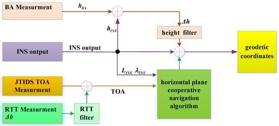
Figure 4.
INS/JTIDS/BA integration architecture.
3.1. Height Filter
INS altitude error Δh and height velocity error ΔVh are the states of the height filter. According to the second-order damped error propagation equation of INS, the state equation of the height filter can be obtained as follows:
where denotes the state vector, and denotes the process noise vector, and covariance matrix Qh is calculated by
where denotes the variance of altitude velocity noise, and T denotes the discrete interval. The state transition matrix is shown in Equation (3).
where denotes the major axis of the earth reference ellipsoid. , where RN denotes the curvature radius of the prime vertical, , where RM denotes the curvature radius of meridian. and are the velocities of east and north, respectively.
The measurement equation is
denotes altitude obtained from BA, denotes altitude obtained from INS, and wh denotes measurement noise [32].
3.2. RTT Filter
The frequency difference is assumed as a first order Markov process, and clock offset is the integral of the frequency difference.
where , and denote the process noise vector, and the state transition matrix can be expressed as
where denotes the correlation coefficient, and the covariance matrix Qk−1 is calculated by
where denotes variance of clock frequency drift. The measurement equation of RTT filter is
where denotes the user’s clock error obtained with RTT, and v is measurement noise of RTT [33].
3.3. Cooperative Navigation Algorithm in Horizontal Plane
In the horizontal plane, the state we estimate is all cooperative members’ longitude and latitude errors of INS. We compute the difference between TOA measurement and calculate pseudo-range, given the measurement equation which describes the relationship between the difference and longitude and latitude errors. Then, error states are estimated with general navigation measurements, cooperative navigation measurements, and predicted error states.
3.3.1. Estimate Time Slice and Arrangement of Time Slot
The architecture of the proposed cooperative navigation algorithm is centralized. One of these cooperative members runs the cooperative navigation algorithm as a computing center unit. The interval of algorithm execution time is a short time slice Tp, and we assume that INS errors do not change much during each interval time Tp. INS errors of cooperative members can be estimated as invariable error states in this period of time.
As shown in Figure 5, each time slice contains many navigation slots. Part of the navigation time slots are occupied by cooperative members to transmit cooperative information messages as cooperative navigation slots, and other navigation slots are occupied by navigation sources to transmit PPLI messages as general navigation slots. General navigation slots and cooperative navigation slots are alternately distributed in each estimate period list.
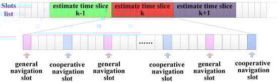
Figure 5.
Estimate period and arrangement of navigation slots.
As shown in Figure 6, we give an example of three cooperative members within one estimate time slice. Navigation slot n, navigation slot n − 2, and navigation slot n − 4 are cooperative navigation slots, and cooperative members c3, c2, and c1 transmit cooperative messages in these navigation slots. Navigation slot n − 1, navigation slot n − 3, and navigation slot n − 5 are general navigation slots, and navigation source s1 and s2 transmit PPLI messages in these navigation slots.
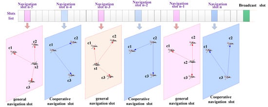
Figure 6.
Relationship of navigation slots and measurements relation.
The information computing center unit used to compute is divided into two parts. One part is the measuring the computing center extracted from PPLI messages and cooperative navigation messages, and the other part is other cooperative members sharing to the computing center unit with cooperative navigation messages.
The shared information of the cooperative member includes measured values of general TOA measurements, positions of the navigation source, measured values of cooperative TOA measurements, the INS output of the cooperative member, and the predicted error states. The computing center will estimate cooperative members’ error states with weighted least squares (WLS) when enough information is collected. Estimate results will be broadcasted, and then these cooperative members revise latitude and longitude errors of INS. The centralized algorithm need the guarantee of network traffic; therefore, the proposed algorithm is more suitable for a small number of cooperative members.
3.3.2. General Navigation Measurements
- Measurement model
If slot n is the general navigation slot, navigation source s transmit a PPLI message. The TOA measurement between the navigation source s and the cooperative member c is given as follows [34]:
where is the actual distance between source s and cooperative member c. and are clock offsets of member c and source s, respectively, and denotes the clock offset of navigation source estimated by the RTT filter, and the clock offset unit is converted from second into meter. denotes TOA measurement noise and is modeled as a zero-mean white Gaussian process.
The calculate distance between cooperative member c and source s in slot n is
where is the earth centered earth fixed (ECEF) rectangular coordinate vector obtained from INS. The calculate pseudo-range is
where denotes cooperative members’ clock offsets, which are approximatively estimated by the RTT filter.
The actual distance between cooperative member c and navigation source s in slot n can be linearized applying a Taylor series around .
is the INS errors vector of cooperative member c. is the true position of navigation source s. The measurement equation can be written as
INS errors are converted from ECEF rectangular coordinates to geodetic coordinates with Equations (A2)–(A4), derivation process is shown in the Appendix A. Equations (A2)–(A4) are substituted into Equation (13), and the equation is simplified.
where , , and denote coefficients after simplification, and denote INS height errors estimated by the height filter of c. and are the longitude and latitude errors of INS, respectively, which want to estimate in the horizontal plane. The measurement equation of the general navigation measurement can be expressed as
where denotes errors of measurement, and denote differences between the true clock offset and the result of the RTT filter namely and , respectively.
- 2.
- Analysis of Measurement Errors
The measurement noise variance is
denotes the errors of the height filter result. We assume that errors are independent of each other. is written as
where denotes the variance of measurement noise, denotes the variance of , which can be estimated by the covariance matrix of height filter, and denote the variance of and , respectively. and can be approximatively estimated by the covariance matrix of the RTT filter.
3.3.3. Cooperative Navigation Measurements
- 1.
- Measurement model
If slot n is the cooperative navigation slot, the TOA between cooperative member c1 and c2 in slot n is given by
where denotes actual distance between cooperative member c1 and c2, and denote time bias of member c1 and c2, respectively, and represents TOA measurement errors modeled as a zero-mean white Gaussian process. and are positions in the ECEF rectangular coordinate system of cooperative and are outputs of INS. The calculate distance between c1 and c2 is
The calculate pseudo-range is
where , denote cooperative members’ clock offsets, which are approximatively estimated by RTT filter.
The actual distance between cooperative member c1 and c2 in slot n can be linearized by applying a Taylor series around
where , denote the true positions of cooperative members. and are INS errors of cooperative members. The measurement equation of cooperative navigation measurement can be presented as follows:
INS errors are converted from ECEF rectangular coordinates to geodetic coordinates with Equations (A2)–(A4). Equations (A2)–(A4) are substituted into Equation (24) and the equation is simplified so that we obtain
Measurement equation of cooperative measurement can be expressed as
where denote errors of measurement and can be expressed as
where , , , denote the longitude and latitude errors of INS. , , , , , denote the coefficients after being simplified. , denote INS heights errors estimated by the height filter and , denote estimate errors of , . , denote differences between the true clock offset and result of RTT filter , .
- 2.
- Analysis of Measurement Errors
The noise variance of cooperative navigation measurement is
We assume that errors are independent of each other; is written as
where denotes the variance of measurement noise, and denote the variance of and , respectively. and can be estimated by the covariance matrix of height filter, and denote the variance of and . and , which can be approximatively estimated by the covariance matrix of the height filter and RTT filter.
3.3.4. State-Transition Equation
The error state vector has 7 dimensions. Each cooperative member will predict its own INS error state locally, and the predicted time interval is the estimate time slice.
State vector contain angle errors, longitude and latitude errors, and east and north directional velocity errors, but only longitude and latitude errors are used for the WLS estimate.
We assume that the current estimate time slice is k, and thus the state equation is
where denotes the state-transition matrix, denotes the process noise vector, T denotes the discrete interval, and the length of T is equal to the short period of time Tp. The state equation predicts according to the second-order damped error propagation equation of INS, and we get matrix A. The noise variance matrix of state equation is
where , , and denote the variance of angle errors, and and denote variance of east and north velocity errors, respectively.
The variance of error state is
3.3.5. Least-Squares Estimation
We assume that there are K cooperative members participating in the cooperative navigation calculation. We estimate all cooperative members’ latitude and longitude errors in one WLS estimator, so the state vector has 2K dimensions.
The corresponding coefficients of are
The TDMA datalink cooperative navigation algorithm can be solved with WLS. We assume that H is a measurement matrix after linearization.
The corresponding weight matrix is
where , , and denote diagonal matrixes whose diagonal elements are reciprocal of corresponding variance of measurements and predicted error states. The iteration process is solved with the Levenberg–Marquardt (LM) algorithm [35].
The weighted least squares solution is Equation [36]:
5. Simulation Experiments and Analysis
We simulated a JTIDS network with multi-access mode of TDMA, and an observed member operated the TDMA datalink cooperative navigation algorithm to evaluate the performance of the proposed algorithm. We processed data of BA, INS, and TOA of JTIDS JUs in a computer.
We generated location, speed, and attitude data of JTIDS members by the preset real trajectories, we and simulated INS errors with the error propagation equation of INS. We added INS errors to real navigation information to simulate INS information and added Gaussian white noise and clock error to the real distance of two network members to simulate TOA measurement.
5.1. Simulation Conditions
Within an area of about 100 km2, we simulated a JTIDS datalink network of 8 members, and these members were simulated as aircraft members. Member 1 was preset as NC of this JTIDS network, and at the same time it also operated as a time reference; the other members would synchronize their clocks with member 1.
Members 1, 3, 5, and 7 positioning with a federated Kalman filter based on INS, GPS, TOA, and BA filters’ structure is shown in Figure 7. Members 1, 3, 5, and 7 could reach a high localization accuracy in this JTIDS network, so they broadcast PPLI messages as navigation sources, and members 2, 4, 6, and 8 were cooperative members positioned with the TDMA datalink cooperative navigation algorithm.
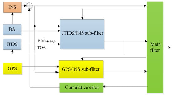
Figure 7.
Filter structure of navigation sources.
The trajectories of the network members are shown in Figure 8: the flight modes of the members including level flight, wheel flight, curve flight, simulation time of 500 s, JTIDS network members’ clock frequency random error of 3 × 10⁻⁶/h, 1-sigma gyro bias error of INS of 0.1° per hour, and the 1-sigma bias error of accelerometer of 0.0001 g.
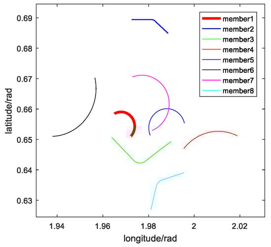
Figure 8.
Horizontal vehicle trajectories of network members.
The basic slot was 7.8125 ms, and the slot interval of two adjoining navigation slots was 8 basic slots. Cooperative members carried out the cooperative navigation algorithm every 500 ms, which means that the algorithm would be carried out every 8 navigation slots, and the estimated time slice Tp was 500 ms. Members 2, 4, 6, and 8 transmitted cooperative navigation information in their navigation slots. Navigation sources broadcast PPLI messages in their navigation slots.
First, we set members 2, 4, 6, and 8 as the observed members and compared the performance of TDMA datalink cooperative navigation algorithm based on INS/JTIDS/BA and EKF based on sequentially processing and the TDMA datalink WLS navigation algorithm without cooperative navigation measurements under the same conditions.
Second, we set member 6 as the observed member and compared the performance of the proposed algorithm with different numbers of cooperative members, and then we analyzed the effect of TOA random errors of measurement and clock calibration accuracy.
5.2. Performance Comparison of Algorithms
The TDMA datalink cooperative navigation algorithm based on INS/JTIDS/BA and EKF based on sequentially processing and TDMA datalink WLS algorithm without cooperative navigation measurement are compared in this part. Cooperative members carry out the compared algorithms in horizontal positioning, and at the same time the same height filter is used. We preset the 1-sigma error of BA to be 50 m, and we preset 1-sigma random noise of pseudo-range measurement to be 3 m.
Compared with the TDMA datalink cooperative navigation algorithm, cooperative navigation measurements are not be used in TDMA datalink WLS.
The state equation of EKF based on sequentially processing is established according to the second-order damped error propagation equation of INS.
The measurement equation is
Cooperative members’ longitude, latitude RMS errors of compared algorithms are presented in Figure 9 and Figure 10. Figure 11 shows the altitude RMS errors of cooperative members.
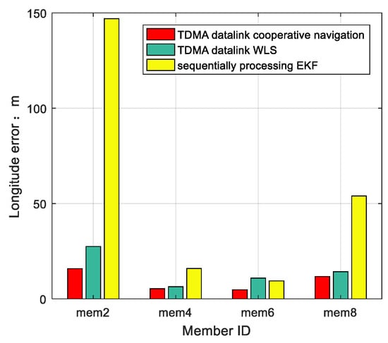
Figure 9.
RMS longitude error comparison between TDMA datalink cooperative navigation, sequentially processing EKF, and TDMA datalink WLS.
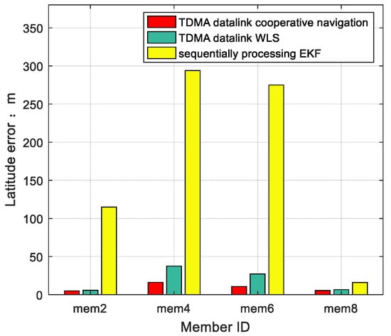
Figure 10.
RMS latitude error comparison between TDMA datalink cooperative navigation, sequentially processing EKF, and TDMA datalink WLS.
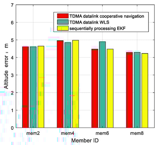
Figure 11.
RMS altitude error comparison between TDMA datalink cooperative navigation, sequentially processing EKF, and TDMA datalink WLS.
Cooperative members’ longitude and latitude errors in every estimate moment are presented in Figure 12 and Figure 13, respectively.
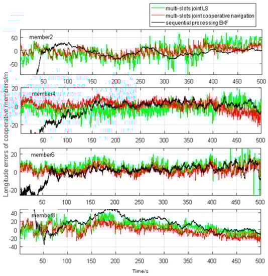
Figure 12.
Longitude error comparison between TDMA datalink cooperative navigation algorithm, sequentially processing EKF, and TDMA datalink WLS.
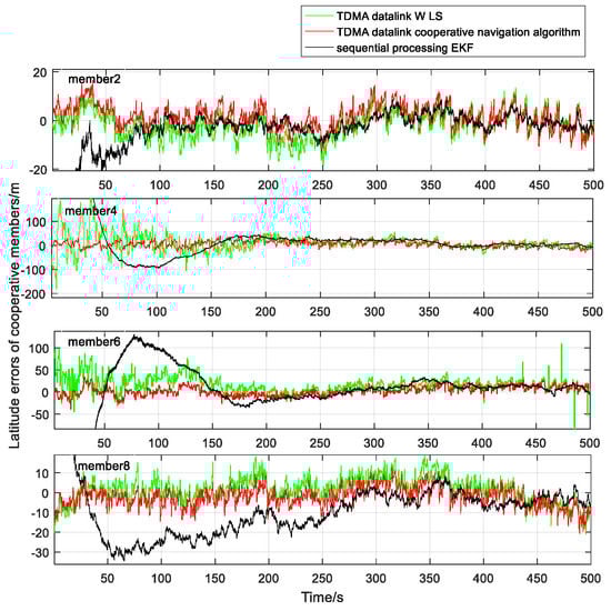
Figure 13.
Latitude error comparison between TDMA datalink cooperative navigation, sequentially processing EKF, and TDMA datalink WLS.
Conclusions can be drawn from the analysis of positioning results in horizontal plane positioning, and positioning precision of the proposed algorithm performs better. A height filter based on BA revises altitude errors of INS in an independent dimension, so the accuracy of the horizontal plane has little effect on altitude accuracy.
5.3. Effect of the Number of Members That Participate in Cooperative Navigation on Localization Accuracy
We set member 6 as the observed member, let member 6 operate the TDMA datalink cooperative navigation algorithm with measurements from different numbers of cooperative members, and compared the performance in different situations.
As shown in Figure 14, in horizontal plane positioning compared with the case calculate without cooperative navigation measurements, more cooperative members mean more cooperative navigation measurements and better WHDOP in the horizontal plane, which leads to better accuracy. Furthermore, altitude accuracy is not affected by the accuracy of the horizontal plane, so it is not changed much.
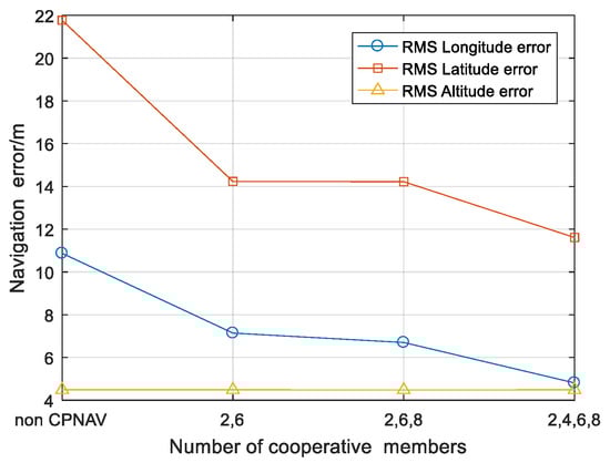
Figure 14.
RMS error comparison between estimates with different numbers of cooperative members.
5.4. Effect of TOA Measurement Random Error on Localization Accuracy
The 1-sigma random error of TOA measurements was set to be 3 m the first time, and then it was increased 3 m at a time. The results of RMS errors are shown in Figure 15.
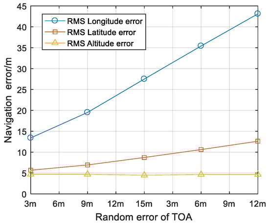
Figure 15.
RMS error comparison of member 6 between different random errors of TOA.
As shown in Figure 14, random errors of TOA measurement effect both general navigation measurements and cooperative navigation measurements, so it mainly affects the accuracy of the horizontal plane. The vertical direction is estimated separately, so random errors of TOA measurements have little influence on accuracy of altitude.
5.5. Effect of Clock Calibration Accuracy on Localization Accuracy
We set member 6 as the observed member, and changed the clock frequency drift of cooperative members to analysis the effect of clock calibration accuracy on localization accuracy.
As shown in Figure 16, clock errors become larger along with the change of clock frequency drift. Clock errors mainly affect TOA measurements, so positioning accuracy of the horizontal plane is more affected. The vertical direction is estimated with BA measurements, so accuracy of altitude is not affected by clock calibration accuracy.
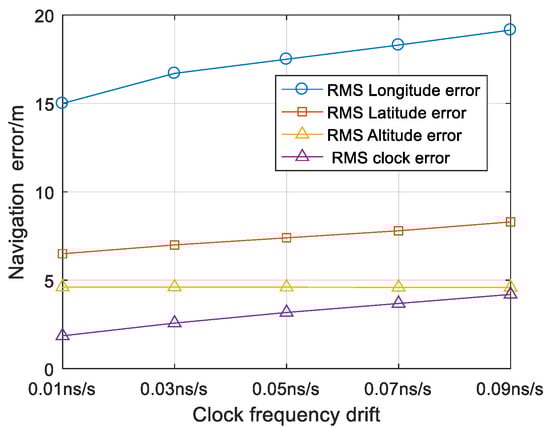
Figure 16.
RMS error comparison of member 6 between different clock frequency drift.
6. Conclusions
The TDMA datalink cooperative navigation algorithm based on INS/JTIDS/BA is proposed in this paper. Members of JTIDS calibrate the clock via RTT, and altitude is located by a height filter independently. In the horizontal plane, a cooperative navigation algorithm is proposed to estimate cooperative members’ longitude and latitude errors of INS. We analyze the effect of cooperative navigation measurements on localization errors in theory. We compare the proposed algorithm with the sequentially processing EKF algorithm and TDMA datalink WLS algorithm without cooperative navigation measurements, and we can draw the conclusion from the analysis of positioning results, namely that the algorithm we propose performs better in the same situation. We show the accuracy of the positioning results with different numbers of cooperative members that participate in cooperative navigation and analyze the effect of random error of TOA measurements and clock calibration accuracy. This provides a theoretical basis for datalink location of the TDMA system.
Author Contributions
S.C., H.Q., L.C., and Y.H. conceived and designed the software; S.C. and H.Q. developed the algorithms; S.C., H.Q., and L.C. debugged the algorithms; all authors wrote the paper. All authors have read and agreed to the published version of the manuscript.
Funding
This research was supported in part by the foundation of Shaanxi Key Laboratory of Integrated and Intelligent Navigation under Grant SKLIIN-20190104 and SKLIIN-20190202.
Data Availability Statement
Data is contained within the article.
Conflicts of Interest
The authors declare no conflict of interest.
Abbreviations
| RELNAV | Relative navigation |
| GNSS | Global navigation satellite system |
| TOA | Time of arrival |
| JTIDS | Joint tactical information distribution system |
| TDMA | Time division multiple address |
| RTT | Round-trip timing |
| HDOP | Horizontal dilution of precision |
| LORAN | Long-range navigation |
| VDOP | Vertical dilution of precision |
| MAV | Micro-aerial vehicle |
| UAV | Unmanned aerial vehicle |
| UWB | Ultra-wide-band |
| WHDOP | Weighted horizontal dilution of precision |
| WDOP | Weighted geometric dilution of positioning accuracy |
| KF | Kalman filter |
| PPLI | Precise participant location and identification |
| GDOP | Geometric dilution of precision |
| MLE | Maximum likelihood estimation |
| CRLB | Cramer–Rao lower bound |
| NC | Navigation controller |
| TR | Time reference |
| BA | Barometric altimeter |
| INS | Inertial navigation system |
| ECEF | Earth centered earth fixed |
| GPS | Global position system |
| EKF | Extended Kalman filter |
| SU | Secondary user |
| PU | Primary user |
| PR | Position reference |
| WLS | Weighted least squares |
Appendix A
The position in ECEF geodetic coordinates can be converted to ECEF rectangular coordinates using the following relation
where f is the flattening coefficient of earth. Total differential of the Equation (60) is
Equations (A2)–(A4) convert , , in the ECEF rectangular coordinate system to , , in the geographic coordinate system.
References
- Pu, Y.; Zheng, X.; Wang, D.D.; Xi, X. Accuracy improvement model for predicting propagation delay of Loran-C signal over a long distance. IEEE Antennas Wirel. Propag. Lett. 2021, 60, 2648–2654. [Google Scholar]
- Su, K.; Jin, S.; Yulong, G. Rapid displacement determination with a stand-alone multi-GNSS receiver: GPS, Beidou, GLONASS, and Galileo. GPS Solut. 2019, 23, 54. [Google Scholar] [CrossRef]
- Aghadadashfam, M.; Mosavi, M.R.; Rezaei, M.J. A new post-correlation anti-jamming technique for GPS receivers. GPS Solut. 2020, 24, 89. [Google Scholar] [CrossRef]
- Yan, W.; Zhao, K.; Li, S.; Wang, X.; Hua, Y. Precise Loran-C signal acquisition based on envelope delay correlation method. Sensors 2020, 20, 1424–8220. [Google Scholar] [CrossRef]
- Xie, D.G.; Wu, N.; Wang, C.; Liu, Q.F. Anti-jamming performance simulation of tactical data link communication system. In Proceedings of the 2012 10th IEEE International Symposium on Antennas Propagation & EM Theory (ISAPE), Xi’an, China, 22–26 October 2012. [Google Scholar]
- Fried, W.R.; Loeliger, R. Principles, system Configure uration and algorithm design of the inertially aided JTIDS relative navigation function. Navigation 1979, 26, 224–236. [Google Scholar] [CrossRef]
- Won, D.H.; Lee, E.; Heo, M.; Lee, S.W.; Lee, J.; Kim, J.; Sung, S.; Lee, Y.J. Selective integration of GNSS, vision sensor, and INS using weighted DOP under GNSS-challenged environments. IEEE Trans. Instrum. Meas. 2014, 63, 2288–2298. [Google Scholar] [CrossRef]
- William, S.W.; Giuseppe, F.G. Stability of the decentralized estimation in the JTIDS relative navigation. IEEE Trans. Aerosp. Electron. Syst. 1983, 2, 240–249. [Google Scholar]
- Altrichter, W.W. JTIDS relative navigation and data registration. IEEE Aerosp. Electron. Syst. Mag. 1992, 7, 42–50. [Google Scholar] [CrossRef]
- Kim, K.; Lee, K.; Lim, J. A RELNAV enhancement for reducing cumulative position error in Link-16 without GRU. In Proceedings of the MILCOM 2016–2016 IEEE Military Communications Conference, Baltimore, MD, USA, 1 November 2016. [Google Scholar]
- Felter, S.C.; Wu, N.E. A relative navigation system for formation flight. IEEE Trans. Aerosp. Electron. 1997, 33, 958–967. [Google Scholar] [CrossRef]
- Liu, W.; Wu, S.; Wu, X. Relative navigation of missile formation and INS error correction methods. In Proceedings of the 29th IEEE Chinese Control And Decision Conference, Chongqing, China, 28–30 May 2017. [Google Scholar]
- Chiang, K.W.; Chang, H.W.; Li, Y.H.; Tsai, G.J.; Tseng, C.L.; Tien, Y.C.; Hsu, P.C. Assessment for INS/GNSS/Odometer/barometer integration in loosely-coupled and tightly-coupled scheme in a GNSS-degraded environment. IEEE Sens. J. 2020, 20, 224–236. [Google Scholar] [CrossRef]
- Alberi, M.; Baldoncini, M.; Bottardi, C.; Chiarelli, E.; Fiorentini, G.; Raptis, K.G.; Realini, E.; Reguzzoni, M.; Rossi, L.; Sampietro, D.; et al. Accuracy of flight altitude measured with low-cost GNSS, radar and barometer sensors: Implications for airborne radiometric surveys. Sensors 2017, 17, 1889. [Google Scholar] [CrossRef]
- Kirkko-Jaakkola, M.; Parviainen, J.; Collin, J.; Takala, J. Improving TTFF by two-satellite GNSS positioning. IEEE Trans. Aerosp. Electron. Syst. 2012, 48, 3660–3670. [Google Scholar] [CrossRef]
- Yu, S.; Nuske, S.; Scherer, S. A multi-sensor fusion MAV state estimation from long-range stereo, IMU, GPS and Barometric sensors. Sensors 2017, 17, 11. [Google Scholar] [CrossRef]
- Kumar, S.; Kumar, R.; Rajawat, K. Cooperative localization of mobile networks via velocity-assisted multidimensional scaling. IEEE Trans. Signal Process. 2016, 64, 1744–1758. [Google Scholar] [CrossRef]
- Kwon, H.; Pack, D.J. A robust mobile target localization method for cooperative unmanned aerial vehicles using sensor fusion quality. J. Intell. Robot. Syst. 2012, 65, 479–493. [Google Scholar] [CrossRef]
- Shalaby, M.; Shokair, M.; Messiha, N.W. Performance of RSS based cooperative localization in millimeter wave wireless sensor networks. Wirel. Pers. Commun. 2019, 109, 1955–1970. [Google Scholar] [CrossRef]
- Li, B.; Wu, N.; Wang, H.; Tseng, P.H.; Kuang, J. Gaussian message passing-based cooperative localization on factor graph in wireless networks. Signal Process. 2015, 111, 1–12. [Google Scholar] [CrossRef]
- Vaghefi, R.M.; Buehrer, R.M. Cooperative localization in NLOS environments using semidefinite programming. IEEE Commun. Lett. 2015, 19, 1382–1385. [Google Scholar] [CrossRef]
- Han, Y.Q.; Wei, C.C.; Li, R.; Wang, J.; Yu, H. A novel cooperative localization method based on IMU and UWB. Sensors 2020, 20, 467. [Google Scholar] [CrossRef] [PubMed]
- Vetrella, A.R.; Fasano, G.; Accardo, D. Satellite and vision-aided sensor fusion for cooperative navigation of unmanned aircraft swarms. Aerosp. Comput. Inf. Commun. 2017, 14, 327–344. [Google Scholar] [CrossRef]
- Yang, C.; Strader, J.; Gu, Y.; Canciani, A.; Brink, K. Cooperative navigation using pairwise communication with ranging and magnetic anomaly measurements. J. Aerosp. Comput. Inf. Commun. 2020, 17, 624–633. [Google Scholar]
- Wymeersch, H.; Lien, J.; Win, M.Z. Cooperative localization in wireless networks. Proc. IEEE 2009, 97, 427–450. [Google Scholar] [CrossRef]
- Salari, S.; Kim, I.; Chan, F. Distributed cooperative localization for mobile wireless sensor networks. IEEE Wirel. Commun. Lett. 2018, 7, 18–21. [Google Scholar] [CrossRef]
- Goel, S.; Kealy, A.; Gikas, V.; Retscher, G.; Toth, C.; Brzezinska, D.G.; Lohani, B. Cooperative localization of unmanned aerial vehicles using GNSS, MEMS inertial, and UWB sensors. J. Surv. Eng.-ASCE 2017, 143, 04017007. [Google Scholar] [CrossRef]
- Zhu, Y.; Yan, F.; Zhao, S.; Shen, F.; Xing, S.; Shen, L. Incentive mechanism for cooperative localization in wireless networks. IEEE Trans. Veh. Technol. 2020, 69, 15920–15932. [Google Scholar] [CrossRef]
- Penna, F.; Caceres, M.A.; Wymeersch, H. Cramér-Rao bound for Hybrid GNSS-terrestrial cooperative positioning. IEEE Commun. Lett. 2012, 14, 1005–1007. [Google Scholar] [CrossRef]
- Ranger, J.F.O. Principles of JTIDS relative navigation. J. Navig. 1996, 49, 22–35. [Google Scholar] [CrossRef]
- Zhao, Y.; Liang, J.; Sha, X.; Yu, J.; Duan, H.; Shi, G.; Li, W.J. Estimation of pedestrian altitude inside a multi-story building using an integrated micro-IMU and barometer device. IEEE Access 2019, 7, 84680–84689. [Google Scholar] [CrossRef]
- Qin, H.; Cong, L.; Zheng, X. A JTIDS/INS/DGPS navigation system with pseudo-range differential information transmitted over Link-16: Design and implementation. GPS Solut. 2012, 17, 391–402. [Google Scholar] [CrossRef]
- Dwivedi, S.; De Angelis, A.; Zachariah, D.; Händel, P. Joint ranging and clock parameter estimation by wireless round trip time measurements. IEEE J. Sel. Areas Commun. 2015, 33, 2379–2390. [Google Scholar] [CrossRef]
- Cao, S.; Qin, H.; Cong, L. Multi-slots joint MLE relative navigation algorithm based on INS/JTIDS/BA for datalink network. IEEE Access 2020, 8, 2169–3536. [Google Scholar] [CrossRef]
- Xu, J.; He, J.; Zhang, Y.; Xu, F.; Cai, F. A distance-based maximum likelihood estimation method for sensor localization in wireless sensor networks. Int. J. Distrib. Sens. Netw. 2016, 2016, 1–8. [Google Scholar] [CrossRef]
- Huang, J.Y.; Wang, P.; Wan, Q.; Chiang, L.P.; Choo, F.H. Dilution of precision for mobile location in Non-Line-of-Sight environments. In Proceedings of the 2010 5th Annual ICST Wireless Internet Conference (WICON), Singapore, 1–3 March 2010. [Google Scholar]
- Sairo, H.; Akopian, D.; Takala, J. Weighted dilution of precision as quality measure in satellite positioning. IEEE Proc.-Radar Sonar Navig. 2003, 150, 430–436. [Google Scholar] [CrossRef]
Publisher’s Note: MDPI stays neutral with regard to jurisdictional claims in published maps and institutional affiliations. |
© 2021 by the authors. Licensee MDPI, Basel, Switzerland. This article is an open access article distributed under the terms and conditions of the Creative Commons Attribution (CC BY) license (http://creativecommons.org/licenses/by/4.0/).