1. Introduction
Linear and planar arrays are extensively used in a wide variety of applications, because they are able to guarantee several advantages, such as the flat profile, the light weight and the beam shaping flexibility. In order to shape the radiation pattern, a complex weighting is typically used [
1]. Amplitude weighting can be easily achieved by means of a beam forming network employing unbalanced power dividers. Phase weighting can be applied by properly dimensioning delay lines at the BFN outputs. An interesting alternative strategy is represented by a phase-only synthesis approach [
2].
In this paper, a simple yet effective technique to achieve a desired beam shape exploiting the physical rotation of the radiating elements around their center axis is proposed. The main advantage of this design methodology resides in its wideband performance, the phase shift being proportional to the rotation and, therefore, frequency independent. In addition, the proposed approach can also be combined with an amplitude weighting in order to further improve beam shaping or side lobe suppression.
Two additional important advantages have to be mentioned. First, the implementation of this type of beam shaping is particularly simple and inexpensive. Second, when avoiding amplitude tapering, as there is no attenuation at radiating element level, the DC to RF power efficiency is maximized. Alternative methods to realize an equivalent amplitude tapering, also compatible with the proposed radiating element, are based on uniformly fed radiating elements arranged in a sparse layouts [
3,
4].
The element rotation technique to generate an arbitrary phase distribution is not new. One of the first applications can be found in [
5], where Kraus adopted helices as radiating elements. More recently [
6], the same approach was adopted, employing a 3-element sequentially rotated array as a single element in a larger array.
In both papers [
5,
6], the radiating element operates on a single frequency band. The element rotation technique has been also exploited for the design of reflectarray and transmitarray antennas [
7], as well as on planar antennas based on modulated metasurfaces [
8].
However, to the authors’ best knowledge, there is no documented solution in the literature employing a center-fed patch antenna with rotation feature capabilities, and there is no prior art on dual-band array antennas based on this phase shifting method.
This paper presents a novel dual-band circularly polarized center-fed patch antenna suitable for the implementation of arrays where beam shaping, based on a phase-only synthesis, is obtained with radiating element rotation.
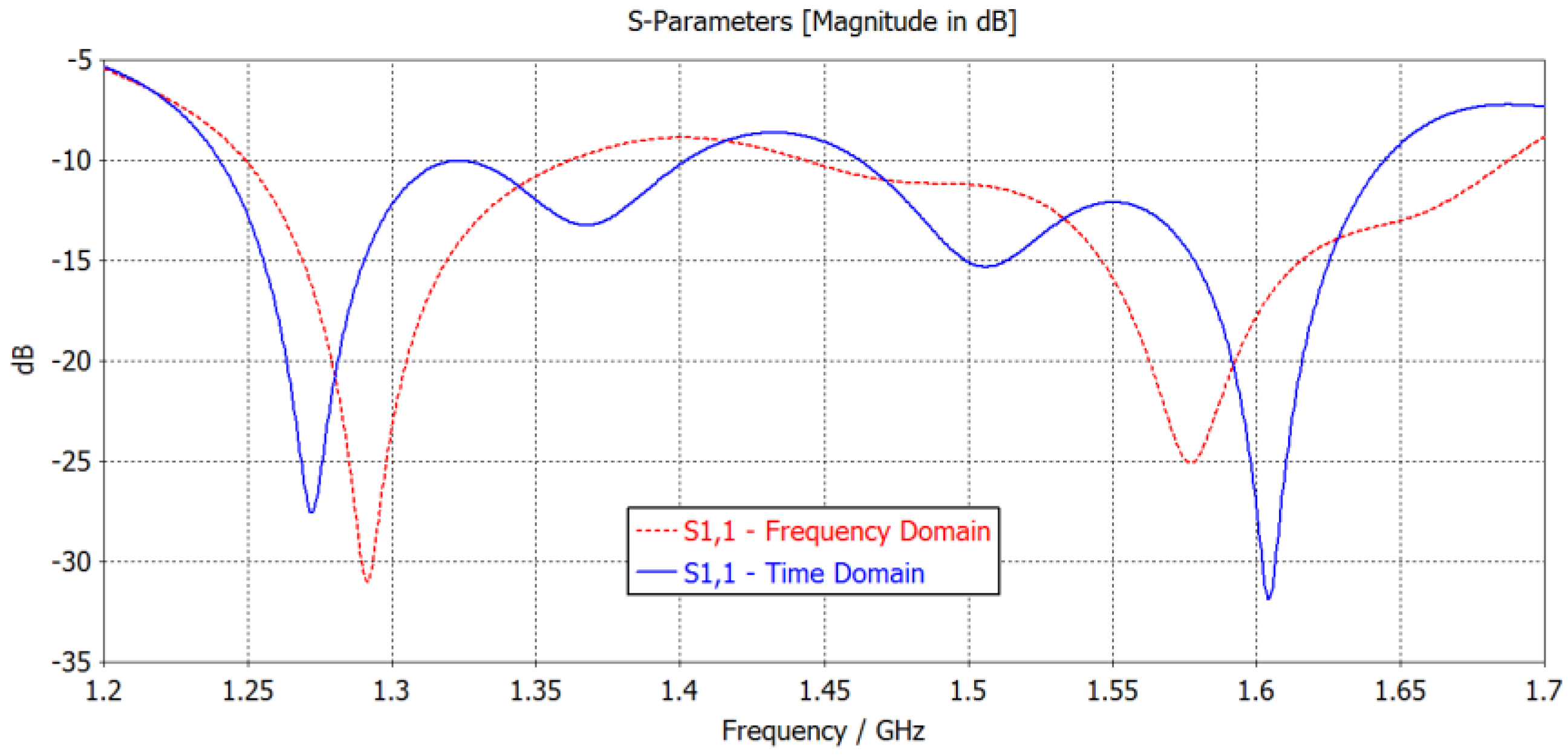
The proposed technique can be applied to any antenna array operating in circular polarization and it is, therefore, suitable for a number of applications, such as radar, telecommunication and remote sensing systems. To illustrate the effectiveness of the proposed radiating element, array architecture and design approach, two different antenna arrays for Global Navigation Satellite System (GNSS) applications are presented. Since every GNSS system requires at least two separate frequency bands to operate, a dual-band radiating element is required. In particular, the European Space Agency’s Galileo system has been selected. The two operative bands are centered at 1.275 GHz and 1.575 GHz, with a return loss higher than 10 dB over 50 MHz on each band, in order to cover both E1 and E6 Galileo bands.
To achieve proper Earth coverage, the radiation pattern shape must be isoflux, as described in [
8,
9]. The phase-only synthesis method is based on the work presented in [
2], further extended to include the effects of the radiating elements rotation. The radiating element and arrays have been designed and validated using the commercial electromagnetic solver CST Microwave Studio, while the phase-only synthesis algorithm has been implemented in MATLAB.
2. The Radiating Element
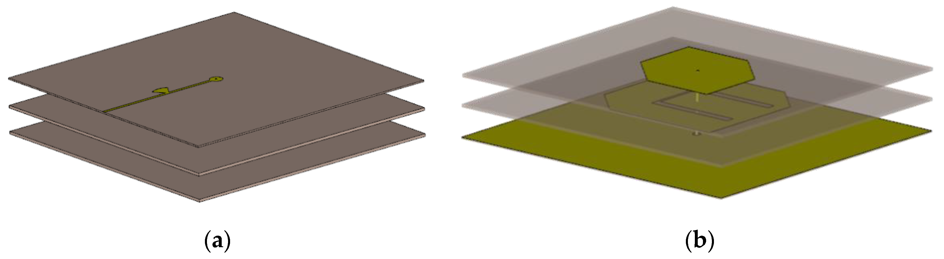
The radiating element proposed in this work has to meet certain requirements, as it must be center-fed, circularly polarized, dual-band, and suitable for the arrangement in an array configuration. A stacked microstrip patch antenna architecture has been therefore selected.
A 3D view of the proposed solution is shown in
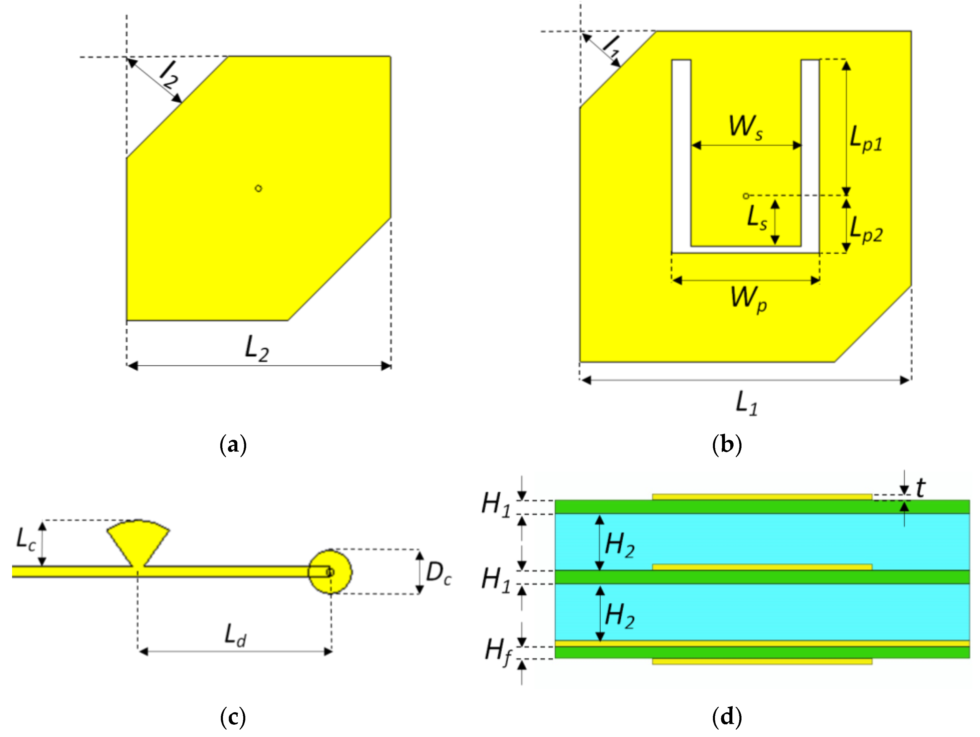
Figure 1. The main geometrical parameters are reported in
Figure 2, and their values listed in
Table 1.
The antenna is made of three layers of Rogers RT6002 substrate separated by air gaps. A parasitic and a main patch are printed, respectively, on the top face of the first and second layers, both with thickness H1, while a 50-ohm microstrip line is realized on the bottom face of the third layer, with thickness Hf. The metal ground plane on the top face of the third layer separates the radiating element from the BFN, thus making the design of these two parts basically independent. All metalizations have thickness t. The antenna is center-fed by a metallic pin with diameter D1, connecting both patches to the BFN microstrip line through a hole on the ground plane with diameter D2. It is worth mentioning that the pin is extended to the parasitic patch, though the same RF performance would have been obtained with a shorter pin only connecting the BFN to the main patch. By electrically connecting both patches to the BFN microstrip line, however, any breakdown issue associated with static charge build-up typical of a space environment is removed.
The pin is connected to the main patch through a wide microstrip section with width Ws, fully enclosed in the patch. To make room for the microstrip, an aperture is, in fact, realized on the central portion of the patch. The aperture length is equal to Lp1 + Lp2, where Lp1 is measured from the center of the pin to the microstrip-to-main patch connecting point, while Lp2 is measured from the center of the pin to the aperture edge at the opposite side. The aperture width is Wp. The parameter Lp1 is used to determine the optimal feeding point and, just as in inset-fed patch antennas, mainly affects the input impedance. The open-circuit stub length Ls also contributes to the input matching. The parameters Lp2 and Wp must be minimized in order to improve the axial ratio bandwidth in the lower frequency band.
Both the main and parasitic patches are squares with side equal to L1 and L2, respectively, and present two properly dimensioned chamfers on opposite sides to generate a circular polarization. The chamfer lengths are I1 for the main patch and I2 for the parasitic. The size of each patch controls its resonance frequency, while the chamfer length affects the polarization purity. It is worth noting that the two square patches and the feeding pin are concentric, so as to allow a rotation around its axis always remaining within the same envelope for any phase configuration. Finally, a capacitive pad of diameter Dc is introduced on the BFN line to facilitate the pin connection and to partially compensate for its inductive contribution. In addition, a 70° radial stub with length Lc. placed at a distance Ld from the feeding point, further contributes to the antenna input matching.
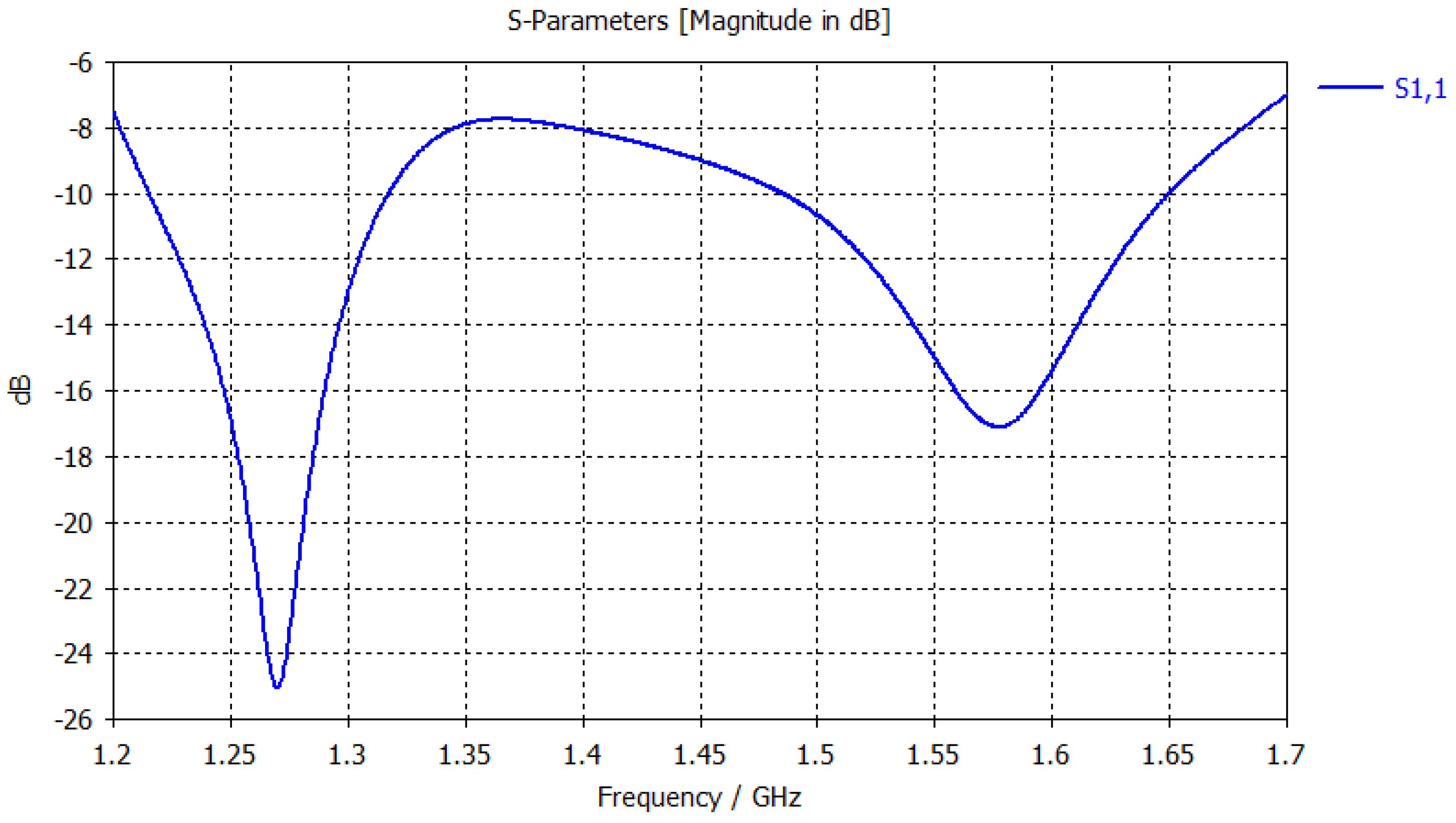
The radiating element has been designed and validated with CST Microwave Studio. The RF performance are reported in
Figure 3,
Figure 4,
Figure 5 and
Figure 6. The radiating element exhibits good performance in terms of input matching and axial ratio. The return loss is better than 13 dB and the axial ratio is lower than 3 dB over on the required frequency ranges. Radiation patterns in both frequency bands are wide-beam and present no nulls in the main lobe region, making them suitable for any array configuration. The maximum realized gain is greater 8 dB over the whole operative frequency range.
3. Phase-Only Synthesis Method
The radiation pattern of a linear array with
N elements spaced
d from one another can be expressed by the well-known formula:
where
represents the single element radiation pattern, usually assumed identical for all elements. This is a valid assumption for configurations with identical and equally oriented radiating elements.
In this specific case, though, radiating elements are rotated with respect to one another. To properly account for the single element radiation pattern, (1) needs to be, therefore, modified as follows:
where
is the radiation pattern of the
n-th element.
When discretizing the angular directions on which the radiation pattern is calculated, (2) becomes:
where
, and
is the number of considered points for the discretized radiation pattern.
In (3), the free-space propagation constant is replaced by , so as to make explicit the radiation pattern dependence on the normalized element spacing .
Equation (3) can also be written in matrix form, a more compact and elegant representation of the radiation pattern:
where the column vector
is the radiation pattern, the elements of the matrix
are evaluated as follows:
and the column vector
is the excitation vector, obtained as the Hadamard product of the two column vectors
and
:
whose elements are simply calculated as:
To shape the beam the phase-only synthesis method presented in [
2] is adopted, for the first time extended in order to account for the effect of the radiating elements rotation.
The proposed methodology makes use of a set of basis functions to represent the phase distribution, which is optimized by tuning the weights of such functions rather than acting at single element level.
It is worth observing that good results are obtained with a limited number of basis functions, independently on the number of the array radiating elements, thus significantly reducing the computational cost, especially for large arrays.
The array phase distribution can be expressed as the weighted sum of a set of
Q basis functions:
where
q is the mode index, while the basis function argument is varying in the range [–1, 1] and it is related to the element number
n by the following expression:
If trigonometric basis functions are adopted then
A valid alternative option is represented by Chebyshev functions:
Even the phase distribution can be expressed in matrix form:
where the elements of the matrix
are given, in the case of trigonometric basis functions, by:
when Chebyshev basis functions are adopted, then the
matrix coefficients are:
From (6) and (12), the array excitation vector is, therefore, given by:
Finally, by combining (4) and (15), the array radiation pattern can be expressed as:
Note that once the element spacing d, the amplitude tapering , the center frequency and the set of basis functions are all defined, the only free variable in (16) is represented by the weight vector , since a phase-only synthesis is performed. This leads to a very fast computation of the radiation pattern at each optimization step, thus further reducing the computational time.
In the next section, two designs are presented, both obtained using Chebyshev basis functions, while the adopted optimization method is a stochastic steepest descent gradient algorithm. Small gradient perturbations are provided by a random choice of the number of points for the radiation pattern, while the step size at each iteration is obtained by optimizing the cost function as a single-variable equation evaluated in the direction of the gradient. These two combined features ensure high robustness of the optimization method and prevent any local minima trapping issue.
The masks adopted to evaluate the cost function are divided into a main beam region and a side lobe region. The main beam region is an isoflux pattern confined between the two following masks:
where
R is the maximum allowed ripple within the upper and lower mask, set to 0.1 dB in the presented designs, while the parameters
and
are both set to 14 in this specific case.
The side lobe region is set to a constant value for . A transition region is defined between the two mentioned regions, corresponding to angles: .
The cost function
C has been defined as the sum of the distances between the pattern and the mask, whenever the pattern exceeds the mask, with two different weights
and
assigned to the main beam and side lobe regions. In addition, a weight
is also assigned to the pattern sidelobe level within the transition region, in order to avoid sidelobes in this angular range.
where
is the main beam region,
is the sidelobe region, and
is the worst sidelobe level in the transition region
.
4. Shaped-Beam Arrays for GNSS Galileo
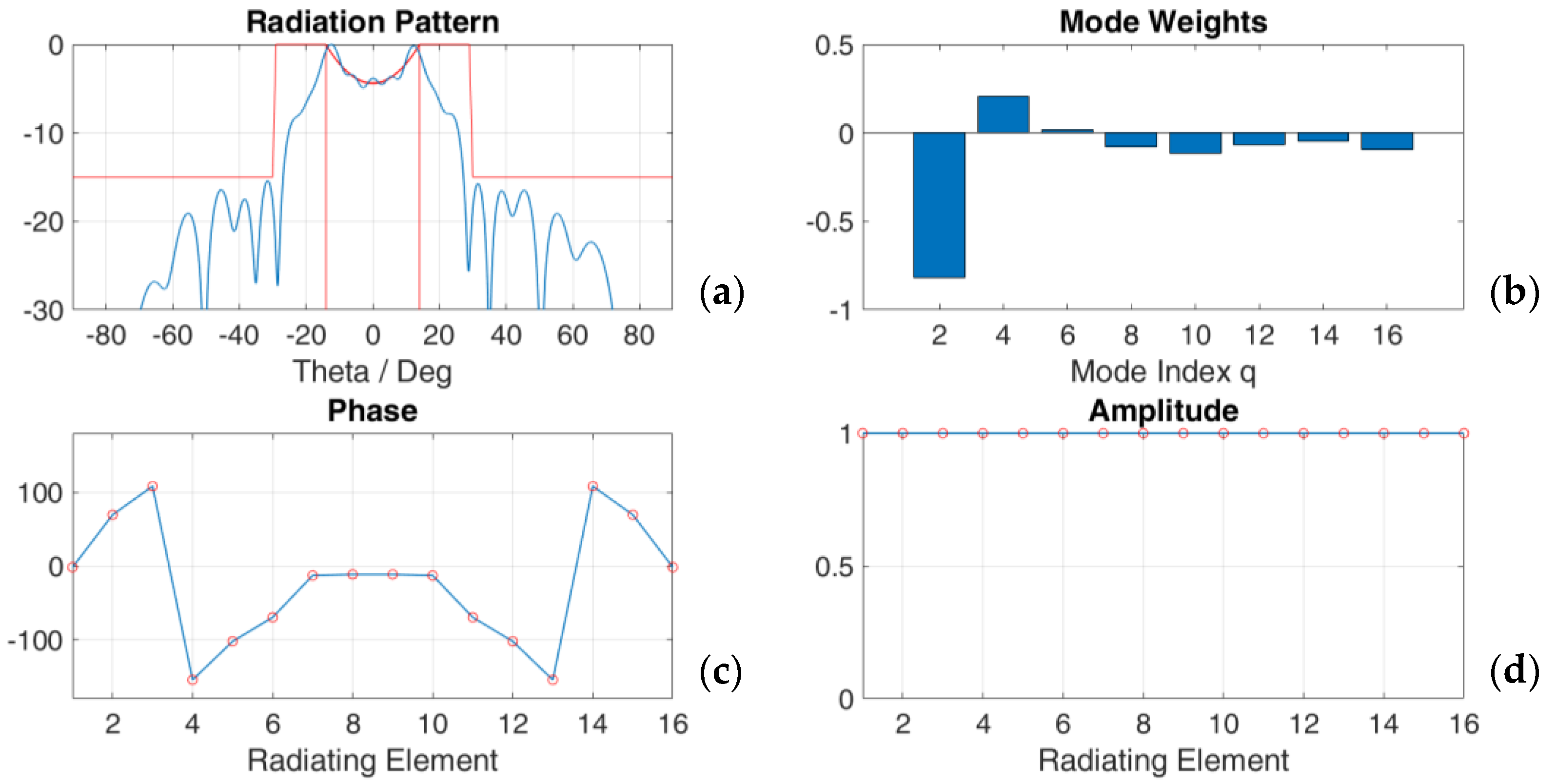
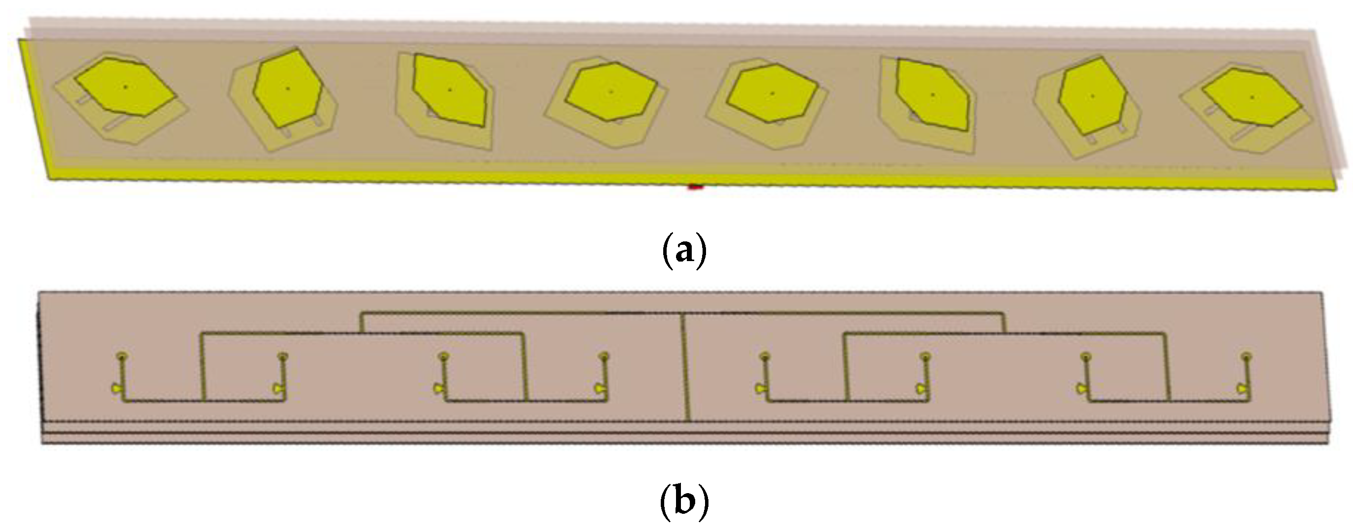
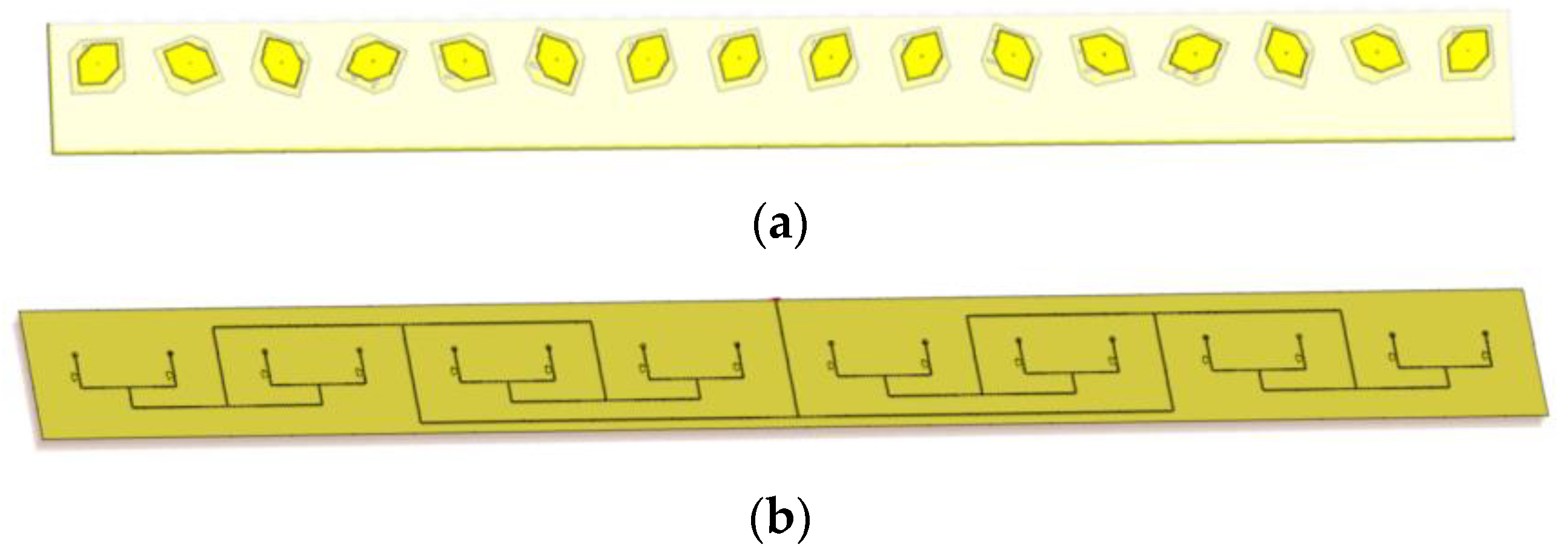
This phase-only synthesis method has been applied to design two linear arrays with shaped beam for the European GNSS Galileo system. The syntheses of an 8-element array obtained with 5 even basis functions and that of a 16-element array, obtained with 8 even basis functions are shown in
Figure 7 and
Figure 8, respectively. In both cases an element spacing equal to 0.65λ
0 has been selected, assuming the average between 1.275 GHz and 1.575 GHz as center frequency. This leads to an element spacing d equal to 136.7 mm. Both optimizations have been achieved with less than 300 iterations and with a computational time of less than 4 s each. Note that the number of adopted basis functions depends on the type of mask selected as also shown in [
2]; however, a limited number of basis functions has been found always sufficient to obtain good results.
The two synthesized arrays have been then implemented on a physical structure using the radiating element described in
Section 2. The BFN is in both cases a microstrip network based on standard T-junctions generating a uniform amplitude distribution.
As in [
5] there is a correspondence one to one between the synthesized phase and the angle defining the physical rotation of the homologous radiating element. Therefore, once the phase tapering has been derived, and the orientation of one patch element is assigned, the orientation of all the other radiating elements is univocally determined.
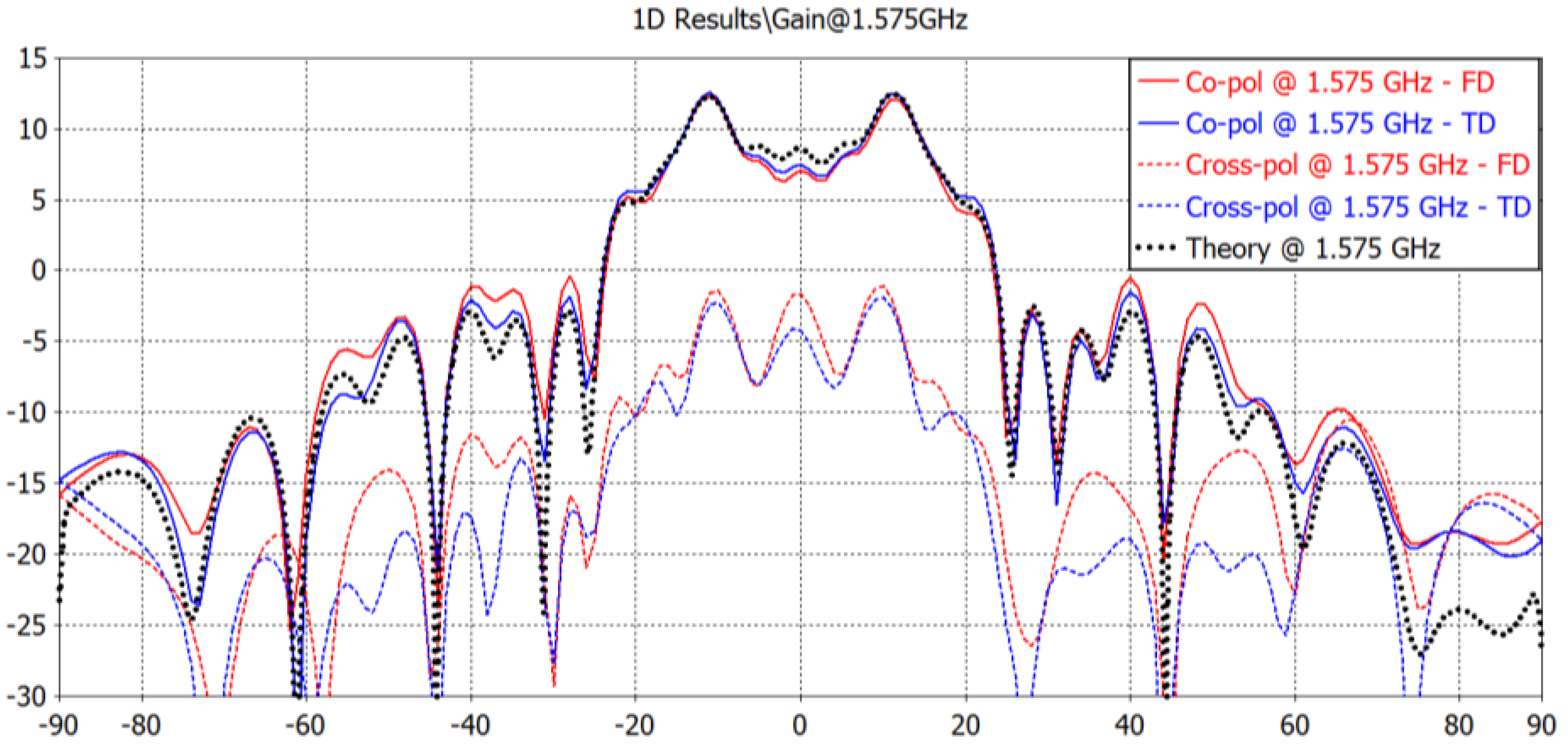
Note that in
Figure 11,
Figure 12,
Figure 15 and
Figure 16 the dotted black plots are the theoretical radiation patterns derived in MATLAB. All the other results have been obtained with rigorous full-wave simulations using the commercial electromagnetic solver CST Microwave Studio, both in the time and frequency domains. The time-domain solver is based on the Finite Integration Technique (FIT), while the frequency-domain solver is based on the finite element method (FEM).
A very good agreement between full-wave and theoretical results can be observed, confirming the effectiveness of the presented design approach as well as the potentialities of the proposed radiating element architecture.
It should be finally observed that the two above design examples have been presented to emphasize the potentialities of the proposed design approach, which is, however, not limited to isoflux beam shapes and can also be applied to larger arrays as well as to planar arrays.
5. Conclusions
An effective phase-only synthesis procedure for circularly polarized antenna arrays has been presented in this work. In addition, the proposed circularly polarized dual-band radiating element design is indeed innovative, thanks to its center-fed architecture. This feature, in combination with a phase-only synthesis and the element rotation technique, guarantees remarkable performance over the two operative frequency bands. The proposed radiating element also exhibits very good performance in terms of input matching and polarization purity on both bands, while maintaining a stable radiation pattern. A complete mathematical formulation of the phase-only synthesis approach has been provided, which takes into account the rotated radiation pattern of each element, thus increasing the synthesis accuracy as clearly shown by the comparison between theoretical and simulated results. To show the potentiality of the proposed solution, two antenna arrays including a BFN have been designed and validated through comparisons with full-wave simulations. Critical issues typical of Space environment such as the static charge build-up and electrical breakdown have been addressed in the design. The proposed solution can be applied to a wide variety of applications, especially when two operative frequency bands are required, making it a very powerful and flexible design approach.


