Article

Adaptive Neural Network Control with Fuzzy Compensation for Upper Limb Exoskeleton in Active Spacesuit

1
School of Aeronautics and Astronautics, University of Electronic Science and Technology of China (UESTC), Chengdu 611731, China
2
Aircraft Swarm Intelligent Sensing and Cooperative Control Key Laboratory of Sichuan Province, Chengdu 611731, China
*
Author to whom correspondence should be addressed.
Electronics 2021, 10(6), 638; https://doi.org/10.3390/electronics10060638
Submission received: 12 December 2020 / Revised: 23 February 2021 / Accepted: 6 March 2021 / Published: 10 March 2021
(This article belongs to the Section Systems & Control Engineering)

Abstract

:
In order to meet the maneuverability requirements of spacesuits for future manned planetary exploration, the concept of an active spacesuit based on the joint-assisted exoskeleton technology is presented. First, by studying the kinematic characteristics of the operator wearing the simulated spacesuit in different gravity environments, we developed a prototype of the upper limb exoskeleton. Then, the resistance moment of the simulated spacesuit was roughly obtained to match the operator’s motion range, being utilized to design the resistance moment model. Considering the unknown resistance moment effects in the active spacesuit and the uncertainties of the exoskeleton’s dynamics model, an adaptive neural network control with fuzzy compensation was developed to drive the upper limb exoskeleton’s tracking desired trajectories. Experimental studies were carried out using an upper limb exoskeleton to illustrate that the proposed method has excellent trajectory tracking performance and good adaptive ability to the gravity environment changes.

1. Introduction

Manned planetary exploration is a favorable way of developing and mastering the manned space capabilities of extraterrestrial celestial bodies. Among them, the manned lunar exploration and space stations have always been popular research targets of the world’s space powers [1], such as the NASA (National Aeronautics and Space Administration) Artemis project and lunar orbital platform-gateway. With the development of manned exploration technology, many tasks, such as installation and maintenance of aerospace equipment, sample collection, patrol inspection, material handling, and some scientific experiments put forward higher requirements for the environmental adaptability, ergonomics performance, and life-sustaining capability of the spacesuit. During a manned planetary exploration mission, the spacesuit can provide astronauts with an appropriate temperature and humidity environment, sufficient oxygen supply, and safe pressure protection. However, the pressure protection will inevitably produce a resistance moment, which will greatly increase the workload and physical energy consumption of the astronauts [2]. For example, the Apollo spacesuit can reduce the force application ability of a single joint by up to 20% on average, while the astronaut’s physical strength can be reduced by up to 50% [3]. Therefore, there is a strong engineering demand to improve the ability of the astronauts to operate on the lunar exploration and space stations through the new spacesuit.
Just as with the current manned space station, which mainly relies on upper limbs and gloves, the low gravity field and uneven terrain on the lunar surface make the mobility of the spacesuit, especially the limb joints, the major consideration. In recent years, scholars have proposed many structural design schemes to improve the joint mobility, for example, using soft joints of spacesuits [4], such as flat pleated joints, corrugated joints, and orange petal joints. The mechanical counter pressure schemes [5,6] and some relevant joint structures have high requirements in terms of materials, and they can only achieve partial pressure protection. The pneumatic joint structures [7] have good joint mobility, but the structures are bloated, resulting in a large deviation from the theoretical isotensive solid surface. The pleated isotensoid joint structure [8], that is, the partial surface of the isotensive body, referring to the folded layout of the flat pleated joint, has good mobility and adaptability. Hard thigh–hip joints [9], which are formed using a series of spherical crown shells with a certain inclined plane, have a complicated structural design and require higher precision and reliability of the rotary bearings. The power assist elbow [10] requires an inflatable bladder with an adjustable valve, which easily leaks air during movement. The X1 robotic exoskeleton [
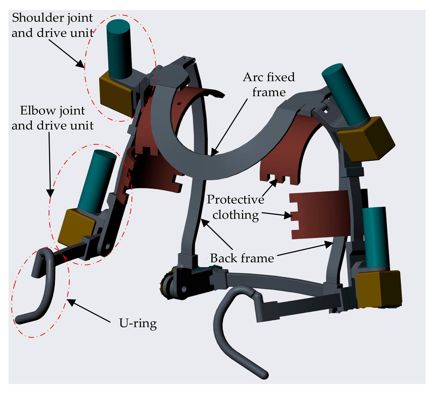
11], as a lower extremity device, can meet the needs of astronauts in orbit countermeasures, such as training the lower-limb muscles and preventing bone density loss and muscle atrophy. On the basis of the existing research results, we present the concept of an active spacesuit, and an upper limb joint-assisted exoskeleton is designed, which can be directly worn outside the spacesuit to achieve the integration or shedding of existing equipment, as well as facilitate joint movement for the astronauts.
Considering the spacesuit’s resistance moment, an important feature is the hysteresis characteristic, that is, the inherent characteristic of materials and structures, reflecting the energy loading and unloading during the bending process of the spacesuit [2]. Therefore, the joint-assisted exoskeleton should accordingly adapt to the resistance moment, and many efforts should be made to employ an accurate resistance moment model into exoskeletons that naturally improve the agility and comfort of the operator wearing the active spacesuit. However, it is a highly challenging task to model the resistance moment of spacesuits, since the resistance moment at a specific angle needs to be tested in advance. For instance, in ref. [12], the resistance moment was obtained by referring to the minimum and maximum values of the joint motion angle of the upper limb. On the basis of previous work and considering the unknown effects [13], we present a resistance moment model based on the fuzzy compensation of the measured resistance moment in a simulated spacesuit.
The upper limb joint-assisted exoskeleton is a multivariable and complex nonlinear system. To ensure the system stability and the tracking of arbitrary trajectories, scholars have proposed some control methods. Vantilt presented a model-based control method to compensate for the exoskeleton dynamics, which relied on modeling the full exoskeleton dynamics and the contacts with the environment [14]. Inel used sliding model control to follow the desired trajectories, an accurate dynamics model of a cable-driven robot was still needed [15]. However, controlled objects usually have the problems of disturbance and parameter errors; thus, it is difficult to obtain an accurate dynamic model in the actual exoskeleton system. The data-driven control method can overcome the absence of the precise knowledge of the exoskeleton’s dynamics, with the free adaptive control method being the most common [16,17]. In 1995, Feng proposed a neural network control based on the computed torque method to compensate for the robot modeling uncertainties [18]. Then, control schemes combining neural network control and other intelligent control were developed. Li developed an adaptive neural network control to approximate the dead-zone effects and robot dynamics [19]. He designed a fuzzy neural network control to identify an uncertain constrained robot model [20]. Lian proposed a self-organizing fuzzy RBFNN (radial basis function neural network) controller to eliminate the dynamic coupling effects between the DoFs (degrees of freedom) of the robotic system [21]. Zhao adopted the RBFNN and feedback compensation to eliminate the unknown nonlinear part for a three-dimensional (3D) laser scanning system, and the fuzzy algorithm was used to adjust the PID (Proportion-Integral-Derivative) parameter [22]. Considering the unknown factors of spacesuit resistance torque and the excellent performance of neural network control, it is reasonable to present an adaptive neural network control with fuzzy compensation for the upper limb exoskeleton.
First, we developed an upper limb joint-assisted exoskeleton according to the kinematic characteristics of an operator wearing the simulated spacesuit in different gravity environments. Then, according to the motion range of the simulated spacesuit, the resistance moment was roughly obtained through the homemade simple joint resistance moment measuring device, which was utilized to design the resistance moment model. Considering the effects of the unknown resistance moment in the active spacesuit and the absence of the precise knowledge of the exoskeleton’s dynamics, an adaptive neural network control of the upper limb exoskeleton is proposed on the basis of fuzzy compensation for the corresponding spacesuit’s resistance moment, which is utilized to drive the exoskeleton’s tracking desired trajectories. In order to verify the effectiveness of the proposed approach, the upper limb exoskeleton prototype was tested. The contributions can be summarized as follows:
(1)
A prototype of the upper limb exoskeleton was developed using the kinematic characteristics of an operator wearing the simulated spacesuit in different gravity environments.
(2)
The resistance moment of the simulated spacesuit was roughly obtained to match the operator’s motion range, and a corresponding resistance moment model was designed.
(3)
Considering the effects of the unknown resistance moment in the active spacesuit and the uncertainties of the exoskeleton’s dynamics, an adaptive neural network control with fuzzy compensation was developed to drive the upper limb exoskeleton’s tracking desired trajectories.

2. Prototype of Upper Limb Exoskeleton

This section describes the prototype of the upper limb exoskeleton, which is directly worn outside the spacesuit to achieve the integration or shedding of existing equipment, as well as facilitate joint movement for astronauts.

2.1. Kinematic Characteristics

In order to investigate the influence of different gravities on the kinematic characteristics of limb joints during space missions, a self-made suspension-type low-gravity experimental frame was designed, and an inertial motion capture system was used to measure the motion range of limb joints, as shown in Figure 1.
As shown in Figure 1, the operator was fixed in the suspension system with a vertical ground posture. The mechanical loading device of the suspension system can realize a constant upward force by constraining the experimenter’s upper arms, forearms, waist, thighs, and calves, thereby simulating the different gravity environments on the planetary surface. According to the standard document and the specific gravity acceleration, we could calculate the bob-weight of each of the operator’s body parts. In addition, the weight of the spacesuit and upper limb exoskeleton could be calculated as a function of their mass distribution, and the corresponding loads were fixed at the experimenter’s waist. The bob-weight was composed of the standard bob-weight (1 kg, 2 kg, 5 kg, 10 kg, and 30 kg) and some steel balls, which could be adjusted according to the weight of different experimenters and gravity accelerations.

2.2. Distribution of Degrees of Freedom

In order to meet the mobility requirements of the active spacesuit, we needed to rationally configure the DoF (degrees of freedom) of the upper limb exoskeleton. Specifically, three DoFs were assigned to the upper limb side, including two DoFs for the shoulder joint and one DoF for the elbow joint, whereas the wrist joint is usually designed as a U-ring to connect with gloves. Due to flexion/extension in the sagittal plane being the main form of upper limb motion, to minimize the additional metabolic rate penalty when mass is added distally during movement [23], we installed two motors on the flexion/extension directions of the upper limb to achieve active movement, and the remaining joints were driven. The DoF configuration and movement form scheme are shown in Table 1.

2.3. Mechanical Structure Design

On the basis of previous work [24], an upper limb exoskeleton was designed, which adjusts the length of the rods to meet different operators. Moreover, we analyzed the stress conditions of the exoskeleton, performed finite element static analysis when selecting single-arm lifting with maximum load, and ensured that the structure size was optimized [25]. There was a rotational degree of freedom between the arc fixed frame and the back frame for the astronauts to quickly put on and take off the exoskeleton. The U-ring was designed to assist astronauts to extract heavy objects, eliminate mechanical vibration, and ensure the stability of the exoskeleton movement. Protective clothing can reduce the stress exerted on the upper limb by the exoskeleton. The overall mechanical structure of upper limb exoskeleton is shown in Figure 2.

3. Resistance Moment

3.1. First-Order Transition Curves

Since a real spacesuit is high-value equipment, we could only customize the simulated spacesuit with a pressurizing device. To obtain the resistance moment, the “fish-scale” method was used in the single-joint assembly or the entire spacesuit system [26], as shown for the built-in robotic spacesuit tester [27] and the flexible single-joint test devices [12]. According to the “fish-scale” method, we established a single-joint resistance moment measuring device [
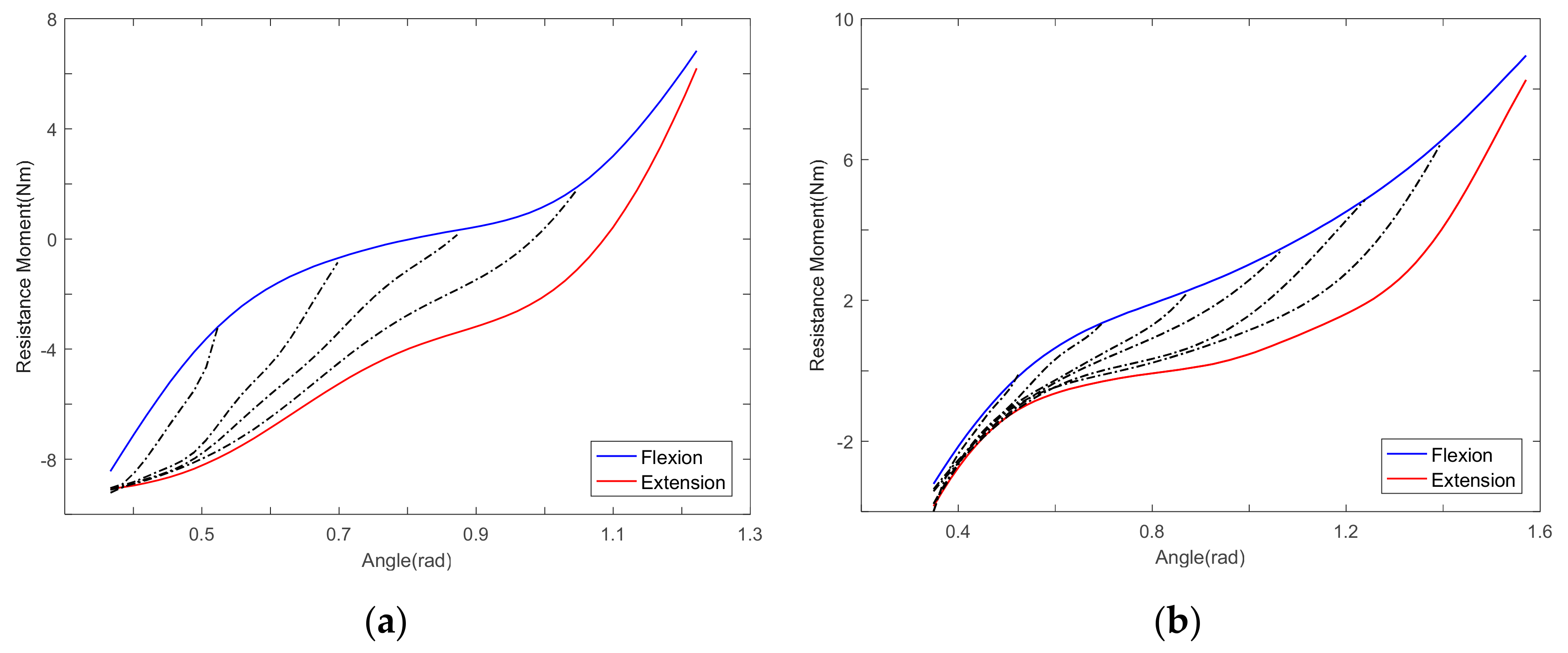
13], where the measurement angle range of the upper limb joints needed to be obtained in advance. We measured the resistance moment when bending from the minimum angle of the joints to different maximum angles before returning to the same minimum angle. The motion ranges of the shoulder joints and the elbow joint were 0.35–1.22 rad and 0.35–1.57 rad, respectively. The resistance moment of the upper limb joints was obtained by fitting the results of multiple measurements, as shown in Figure 3.
As shown in Figure 3, we obtained the first-order transition curves, indicating that the resistance moment is not only related to the current joint angle, but also the motion direction of the joints [
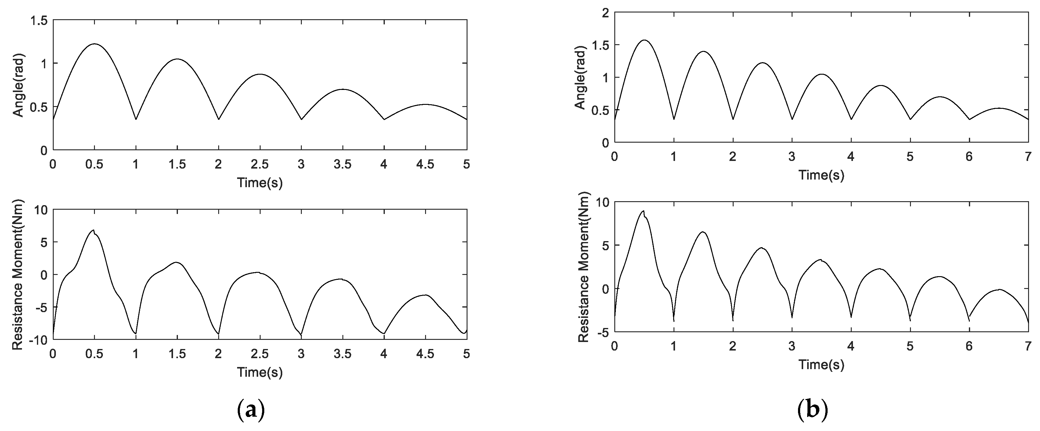
24], in which flexion is defined as bending from the minimum angle of the joints to the maximum angle, whereas extension is movement in the opposite direction. It was necessary to obtain the motion range of the joints in advance, before manually measuring the resistance moment corresponding to the spacesuits. Given a known motion range of upper limb joints, we can then obtain the transition time–angle curves (resistance moment), as shown in Figure 4.
As shown in Figure 4, even if the motion ranges were known, some measurement errors could cause sudden changes in the resistance moment, especially when the direction of motion changed. However, the real motion situation of human spacesuit systems involves multiple DoFs, especially for shoulder joints, and some motion angles are unknown in advance. Therefore, below, we present a resistance moment model for the simulated spacesuit.

3.2. Resistance Moment Model

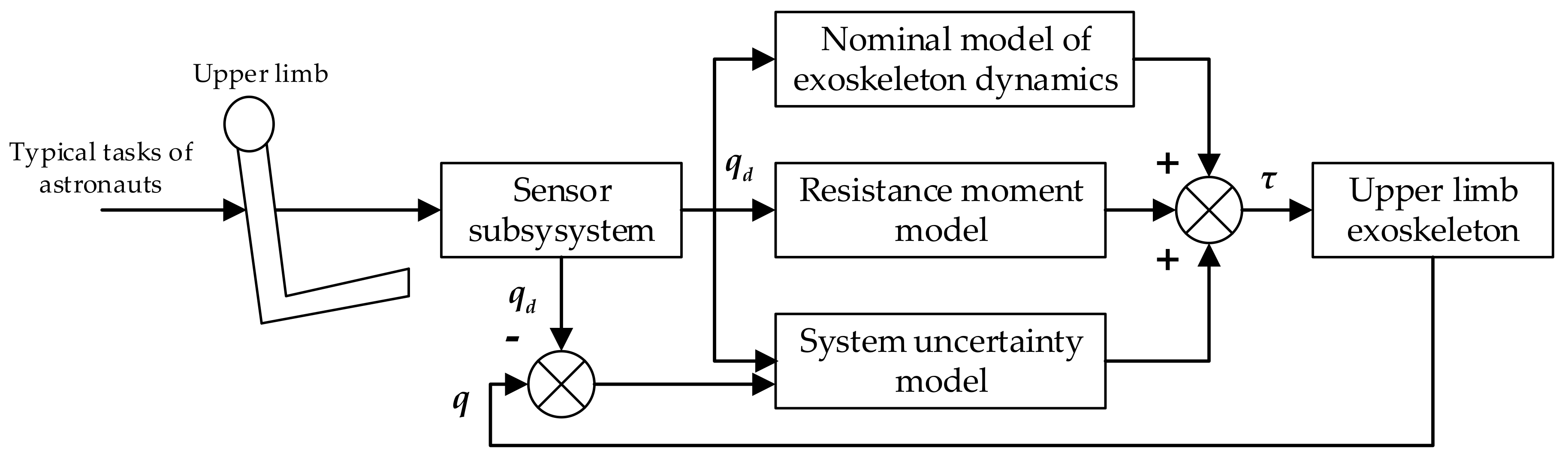
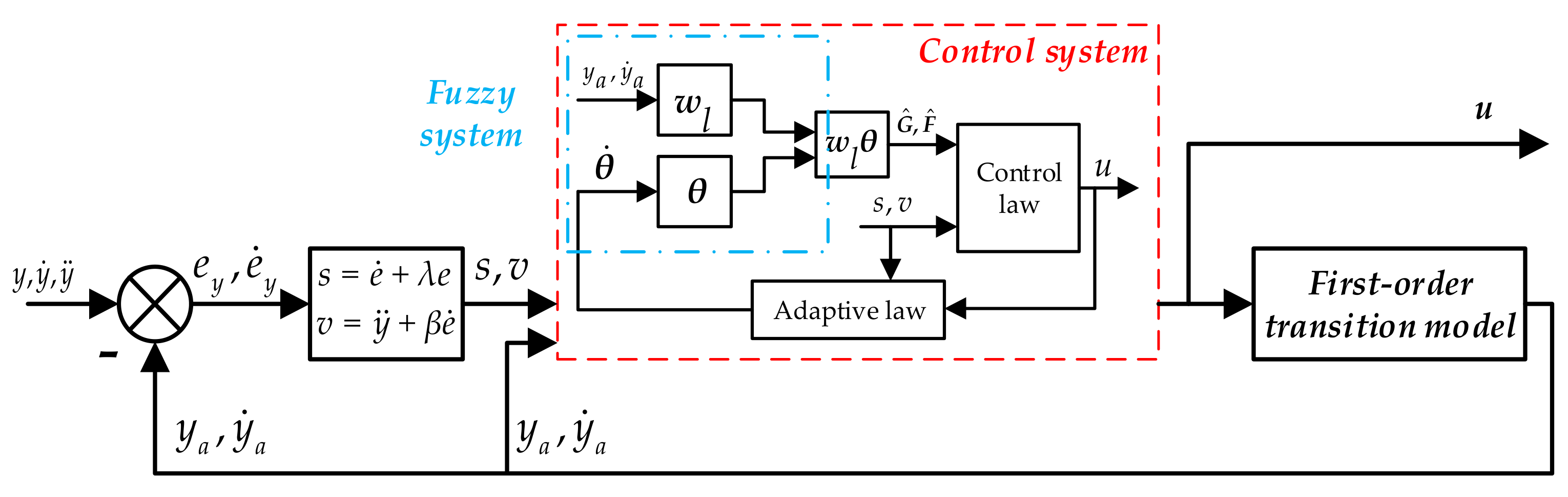
From the above description, we obtained the first-order transition curves by fitting the measured resistance moment data. However, the first-order transition curves could not achieve the spacesuit resistance moment calculation for all typical astronaut movements. Therefore, we decided to establish a resistance moment model with fuzzy compensation, as shown in Figure 5.
According to a nonlinear system equation [28,29], the unknown resistance moment control model of the upper limb exoskeleton could be described as
y i r i = f i x + j = 1 i g i j x   u j ,
where x = [ y 1 , y ˙ 1 , , y i , y ˙ i ] is the state vector, u is the resistance moment vector, y is the joint angle vector, and f(x), g(x) are the unknown positive definite matrix.
Due to the different first-order transition curves, we developed different resistance moment models corresponding to the elbow joint and shoulder joint. For example, the resistance moment model of the shoulder joint was composed of a control system and first-order transition curves. The input of the control system was the tracking error function after filtering s, v, and state vector x = [ y a 1 , y ˙ a 1 , y a 2 , y ˙ a 2 ] , and the output was the resistance moment u. The first-order transition curves could output the corresponding angle ya and angular velocity y ˙ a through the resistance moment u input. By designing the control law u(t), all variables of the closed-loop system were guaranteed to be bounded, and the curves output ya could track the desired joint angle y, whereas the system output u was the desired resistance moment.
The tracking error function after filtering was defined as
s i t = d d t + λ i r i 1 e y i t ,
where the tracking error is e y = y y a , e ˙ y = y ˙ y ˙ a . The time derivative of si(t) was obtained as
s ˙ i = v i - f i x j = 1 p g i j x u j ,
where v i = y i r i + β i , r i 1 e y i r i 1 + + β i , i e ˙ y i , β i , j = r i 1 ! r i j ! j 1 ! λ i r i j , and j = 1, …, ri−1.
Then, Equation (3) can be described as
s ˙ = v F x G x u ,
where s t = [ s 1 t s i t ] T , and v t = [ v 1 t v i t ] T .
When the nonlinear functions F(x) and G(x) are known, the linear control law u(t) is
u = G−1(x)(−F(x) + v + K0s),
where K 0 = d i a g [ k 01 , , k 0 i ] ,   k 0 i > 0 .
However, when F(x) and G(x) are unknown, we can use fuzzy systems to approximate the unknown functions fi(x) and gij(x). By using the Gaussian fuzzifier, product inference engine, and center-average defuzzifier, the outputs of the fuzzy system for approximate unknown nonlinear functions fi(x) and gij(x) can be described as f ^ i x , θ f i = w f i T x θ f i , g ^ i j x , θ g i j = w g i j T x θ g i j , where w f i and w g i j represent the fuzzy basis function vector, and θ f i and θ g i j represent the adaptive parameter vector.
Now, using F ^ x , θ f and G ^ x , θ g   instead of F(x) and G(x) in Equation (5), considering the non-singularity of G ^ x , θ g   and adding a constant coefficient, the subsequent control law can be described as
u = G ^ T x , θ g ε 0 I p + G ^ x , θ g G ^ T x , θ g 1 F ^ x , θ f + v + K 0 s + k 1 G ^ x , θ g s
The adaptive laws is θ ˙ f i = η f i ξ f i x s i , θ ˙ g i j = η g i j ξ g i j x s i μ c j k 1 s j , where k1 > 0, η f i > 0, η g i j > 0. By designing the adaptive control law, the trajectory tracking error of the whole system and its derivatives uniformly converge to 0.

3.3. Simulation Results

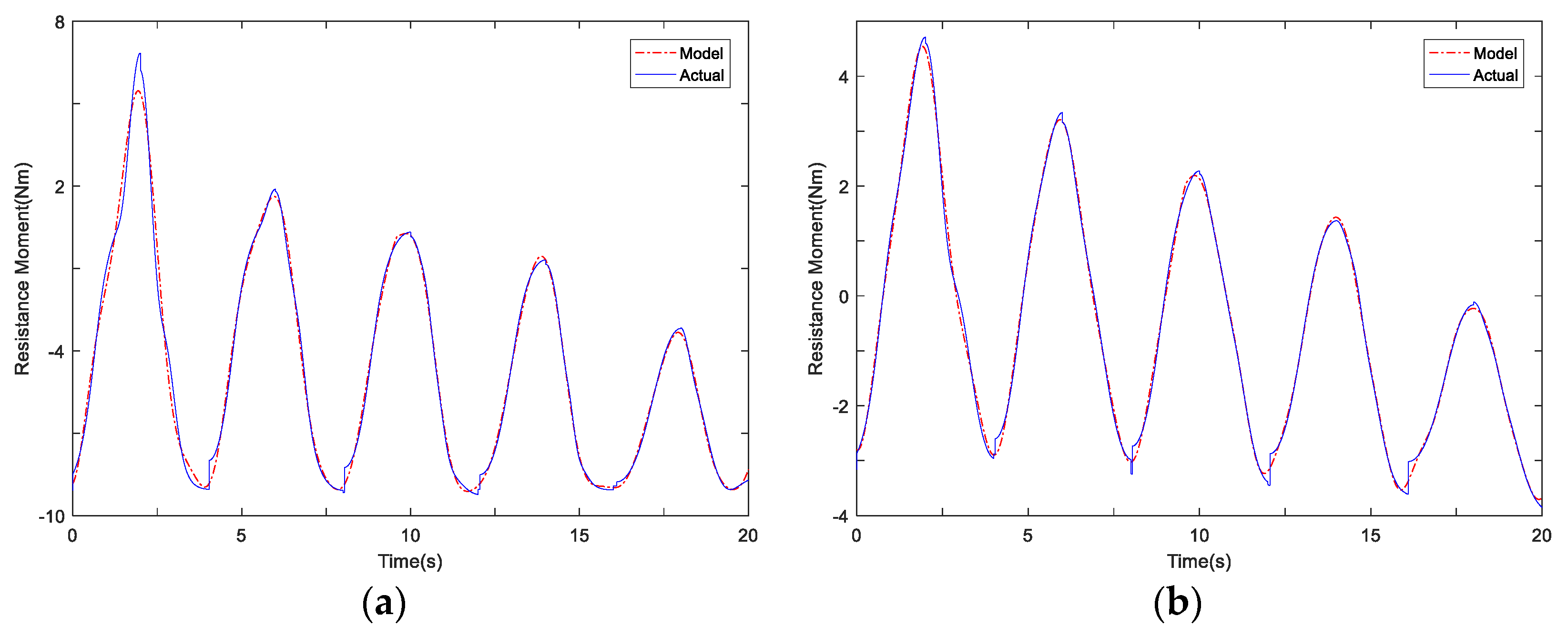
When given a known desired trajectory, we can obtain the actual resistance moment through the single-joint resistance moment measuring device. On the basis of the measured resistance moment, we used the data fitting method to establish the first-order transition curves of the upper limb joints. As a result of the fitting method, some measurement errors tended to cause sudden changes in the time–resistance moment curves. In this section, a related simulation study was conducted to compare the first-order transition curve and the resistance moment model, as shown in Figure 6. The design parameters were λ1 = 400, λ2 = 300, K0 = 15I2, k1 = 20, ε0 = 0.1, Ip= I2 = diag [1, 1], η f i = 0.5, η g i j = 0.5(i,j = 1, 2). We used the Gaussian fuzzifier, product inference engine, and center-average defuzzifier to design the fuzzy system; the parameters of the fuzzy system were as follows:
The membership function μ F i l x i = exp 1 2 x i + 2 l × 1.5 0.55 2 (i = 1, 2, 3, 4, l = 1, 2, 3);
The fuzzy basis function w l x = i = 1 4 μ F i l x i / l = 1 3 i = 1 4 μ F i l x i .
Compared with the first-order transition curves, the curves obtained from the resistance moment model did not show sudden changes in moment when the direction of motion changed, and the maximum moment errors of upper limb joints were 1.4608 N·m and 0.3641 N·m, respectively, thus proving the effectiveness of the resistance moment model.

4. Control System

4.1. Exoskeleton Dynamics

The dynamics of the upper limb exoskeleton with resistance moment could be described as
τ = M q q ¨ + C q , q ˙ q ˙ + G q + R q , q ˙ + d q , q ˙ , q ¨ ,
where q n is the angle of the upper limb exoskeleton, τ n is the desired joint torque input vector, M(q) n is the symmetric, bounded, positive definite inertia matrix, C q , q ˙ n represents the Coriolis and centrifugal torques, G(q) n is the gravitational force vector, R q , q ˙ n is the resistance moment vector, and d q , q ˙ , q ¨ n is the external disturbance vector. We assume that the external disturbance d q , q ˙ , q ¨ is uniformly bounded and the desired trajectory qd is continuous and known.

4.2. Control Design

Considering the uncertainties of the exoskeleton’s dynamics, we previously proposed RBFNN control based on the computational torque method [30]. Here, the computational torque method converts the nonlinear system into the corresponding linear system, which can eliminate the influence of coupling between joints, as well as improve the calculation efficiency. It was assumed that there are no external disturbances d q , q ˙ , q ¨ in the system, and the control law of the computational torque method could be described as
τ = M q u + C q , q ˙ q ˙ + G q + R q , q ˙ ,
where u = q ¨ d + k v q ˙ d q ˙ + k p q d q = q ¨ d + k v e ˙ + k p e , q d , q ˙ d , and q ¨ d are the desired joint angle, angular velocity, and angular acceleration, and kv and kp are the proportional and differential gain coefficients. The resistance moment R q , q ˙ is obtained using the first-order transition curves.
Substituting Equation (8) into Equation (7), the error equation of the system becomes
e ¨ + k v e ˙ + k p e = 0 .
By choosing the appropriate coefficients kv and kp, the trajectory tracking error gradually converges to 0 in the exoskeleton system. However, since there are uncertainty terms such as clearance and friction, which cannot be compensated for and eliminated by the traditional computational torque method, we propose RBFNN compensation to improve control system accuracy.
We adopted the nominal model, with M0(q), C0(q, q ˙ ), and G0(q), and then the nominal model of the exoskeleton dynamics was generated as follows:
τ = M 0 q u + C 0 q , q ˙ q ˙ + G 0 q + R 0 q , q ˙ .
Substituting Equation (10) into Equation (7), the error equation of the system becomes
e ¨ + k v e ˙ + k p e = M 0 1 Δ M q ¨ + Δ C q ˙ + Δ G + Δ R d ,
where ΔM = M0 − M, ΔC = C0 − C, ΔG = G0 − G, and ΔR = R0 − R; the system uncertainty vector is
f x = M 0 1 Δ M q ¨ + Δ C q ˙ + Δ G + Δ R d .
Since the nonlinear uncertain term f(x) is unknown, and since RBFNN can be used to approximate the unknown function, the control law of RBFNN based on the computational torque method is
τ = M 0 q u f x + C 0 q , q ˙ q ˙ + G 0 q + R 0 q , q ˙ .
In this paper, the resistance moment R q , q ˙ was obtained using the resistance torque model. Considering the approximation error of neural networks, we present an adaptive neural network control for the upper limb exoskeleton, where the modified control law is
τ = τ 1 + τ 2 + τ 3 ,
where the nominal model of exoskeleton dynamics τ 1 = M 0 q u + C 0 q , q ˙ q ˙ + G 0 q , the resistance moment model τ 2 = G ^ T x , θ g ε 0 I p + G ^ x , θ g G ^ T x , θ g 1 F ^ x , θ f + v + K 0 s + k 1 G ^ x , θ g s   , and the optimal system uncertainty τ 3 = θ * T φ x , and θ is the optimal weight. The overall control system for the upper limb exoskeleton in the active spacesuit is illustrated in Figure 7.
The approximation error of the neural network is
ε = f x f ^ x , θ = η θ ˜ T φ x ,
where the optimal bounded approximation error η = f x f ^ x , θ , and θ ˜ T φ x = f ^ x , θ f ^ x , θ . The parameter adaptive law is
θ ^ ˙ = γ φ x x T P B + k 1 γ x θ ^ ,
where γ > 0, k1 > 0, P A + A T P = Q , P is the symmetric positive definite matrix, and Q ≥ 0.

5. Experimental Studies

5.1. System Description

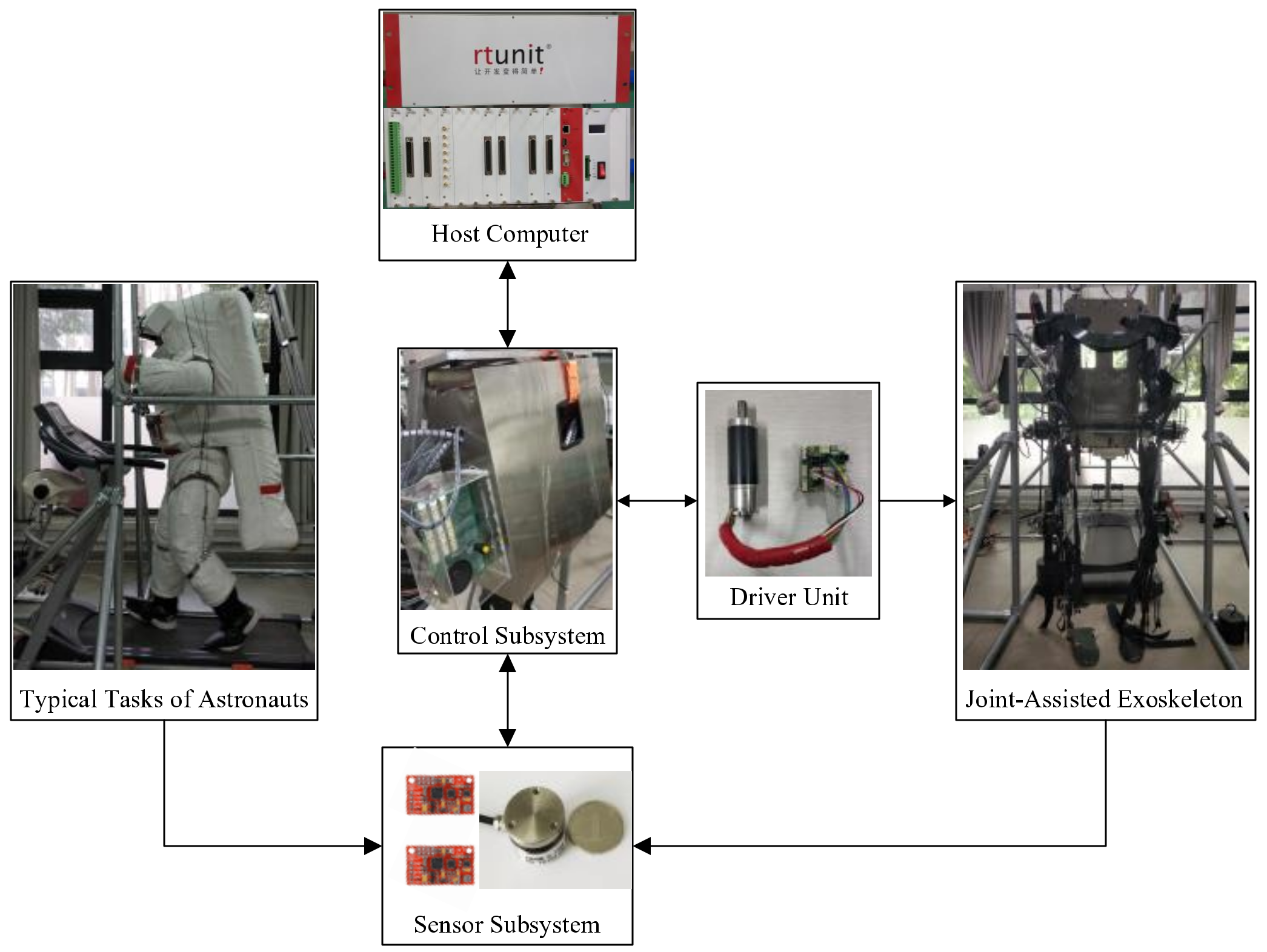
The exoskeleton experimental platform consisted of a joint-assisted exoskeleton, drive unit, control subsystem, host computer, sensor subsystem, and low-gravity experimental platform, as shown in Figure 8. The drive unit was composed of a Maxon motor (EC-i series) and matched EPOS4 driver.
Before the test experiment, a series of preparatory steps were completed.
(1) Parameter measurement. Parameters such as the experimenter weight, dimensions of each body segment, and simulated space suit mass were calculated. First, we determined the exoskeleton rods according to the dimensions of each body segment of the experimenter. Then, combined with a standard document [31], we determined the bob-weight according to the weight of the experimenter, the simulated spacesuit, and the exoskeleton prototype, thus simulating different gravitational acceleration environments.
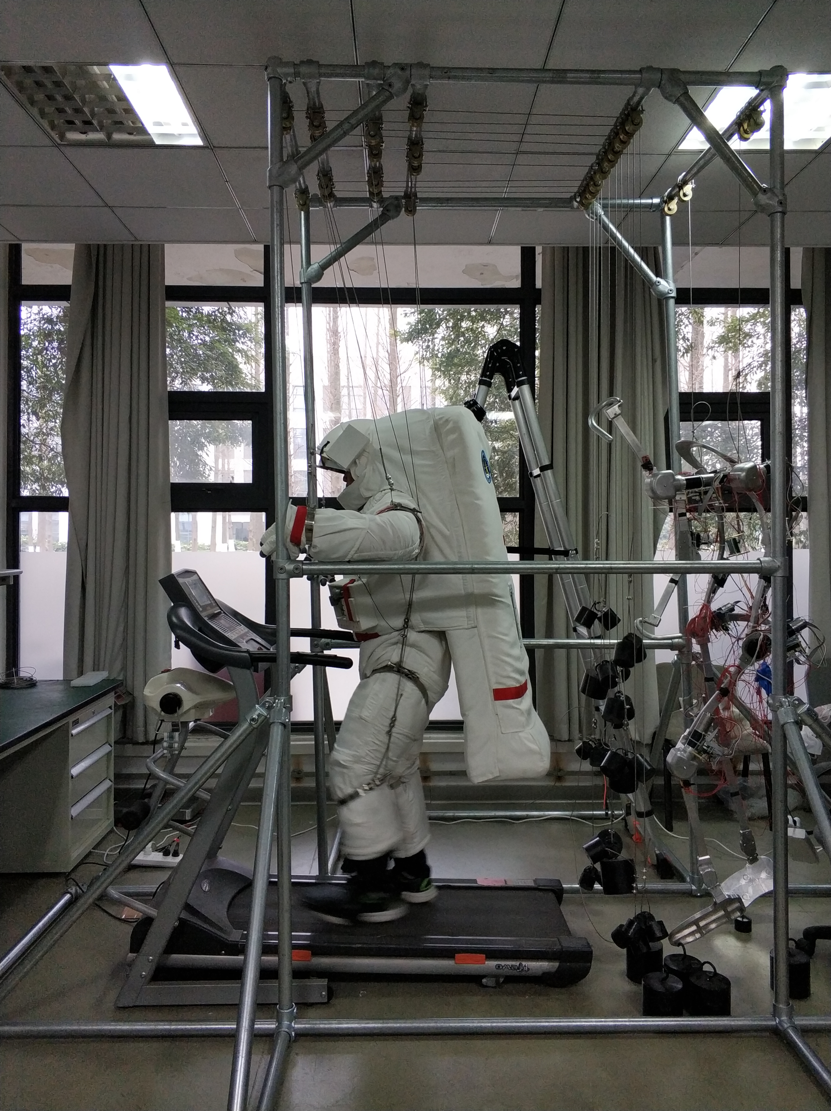
(2) Equipment installation. We needed to install sensors on the upper limbs of the experimenter, and we confirmed the accuracy of the test signal through debugging. Then, the experimenter put on the simulated spacesuit and used the pressurizing device to adjust the pressure environment. Next, the experimenter put on the upper limb joint-assisted exoskeleton and used clamps to fix the exoskeleton at the center of the upper arms and forearms. Lastly, the experimenter was fixed in the suspended low-gravity experimental frame and completed the typical tasks of astronauts.
(3) Adaptability training. The experimenter was asked to carry out 10 min of typical tasks in the suspended low-gravity experimental frame, where we could adjust the relevant equipment position according to the experimenter joint-assisted feedback and sensor signal.
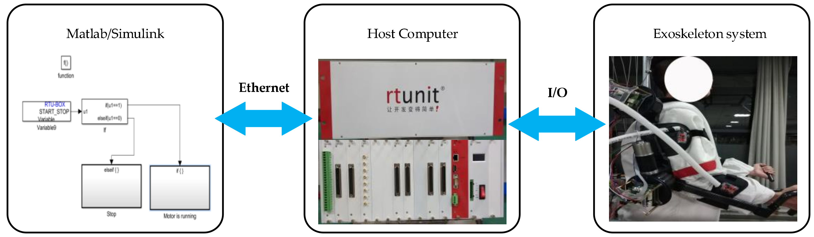
When the above preparatory steps were completed, we could verify the effectiveness of the control algorithm. The real-time simulation system is illustrated in Figure 9.
The control model was built using Matlab/Simulink software; then, by compiling and connecting the host computer through the Ethernet interface, the main board RTB1802 obtained the control codes and started to run the control system. The main board RTB1802 converted the control algorithm into a digital quantity, and then RTB1806c converted it into an analog quantity and transmitted it to the EPOS4 driver. When the Maxon motors were running, the encoder ENX16 obtained the rotating position of the motors and generated pulse signals, while the board card RTB1808c obtained these pulse signals in real time, which could be transmitted to the main board RTB1802 for closed-loop control of the position ring after corresponding conversion. The six-dimensional torque sensors generated the voltage signal, which was converted into a digital quantity and transmitted to the main board RTB1802 for closed-loop control, so as to improve the control accuracy of the force.

5.2. Experiment Validation

To verify the superiority of the proposed control method under three gravitational acceleration environments, we set up three gravitational environments by adjusting the bob-weight: Earth gravity (1 g), Mars gravity (1/3 g), and Moon gravity (1/6 g). The weights of the experimenter, the simulated spacesuit, and the exoskeleton prototype were 71 kg, 26 kg, and 15 kg, respectively, and we assumed that the weight distribution of the simulated spacesuit and the exoskeleton prototype was consistent with that of the human body.

5.2.1. Earth Gravity

In the Earth’s gravity environment, the design parameters of the RBFNN control based on the computational torque method were as follows: kv = diag[3 0,75], kp = diag[225,750], ci = [−2 −1 0 1 2], and bi = [3 3 3 3 3] (i = 1,2,3,4,5). The design parameters of the proposed method in this paper were as follows: kv= diag[9,9], kp = diag[6,6], ΔM/M = 0.3,ΔC/C = 0.3, ΔG/G = 0.3, ci = [−1.5 −0.5 0 0.5 1.5], bi = [3 3 3 3 3] (i = 1,2,3,4,5), A = [zero(2),eye(2); −kp, −kv], Q = diag [100,100,100,100,100], γ = 20, k1 = 0.001, and external disturbance 
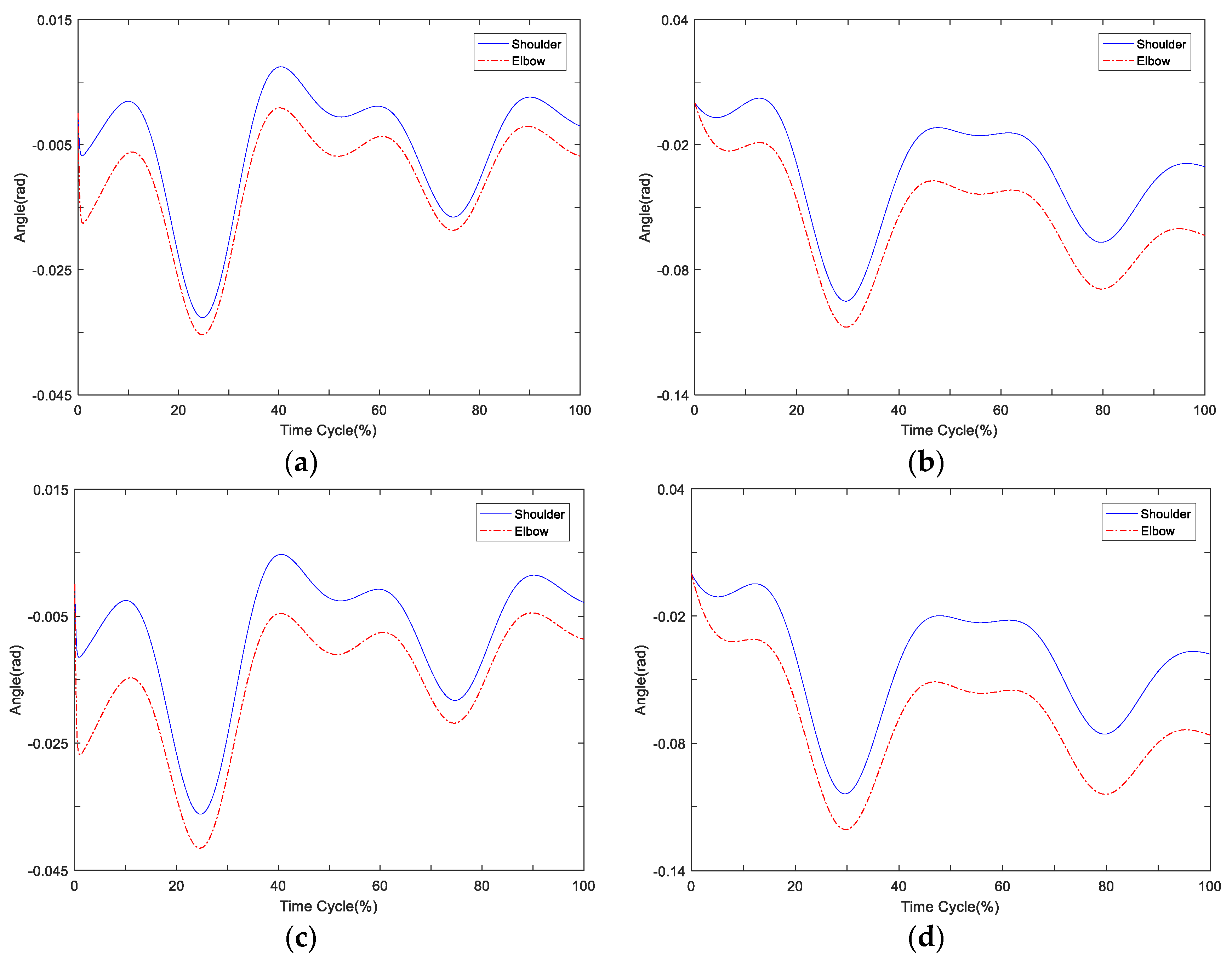
d = [0.2 × sin(t); 0.2 × sin(t)]. We assumed that the time cycle of joint motion was 2 s. The tracking errors for upper limb joints are shown in Figure 10.

5.2.2. Other Low Gravity

According to the standard document [31], we could calculate the bob-weight of the upper limb of the experimenter, the simulated spacesuit, and the exoskeleton prototype; the bob-weight scheme of a single arm is shown in 
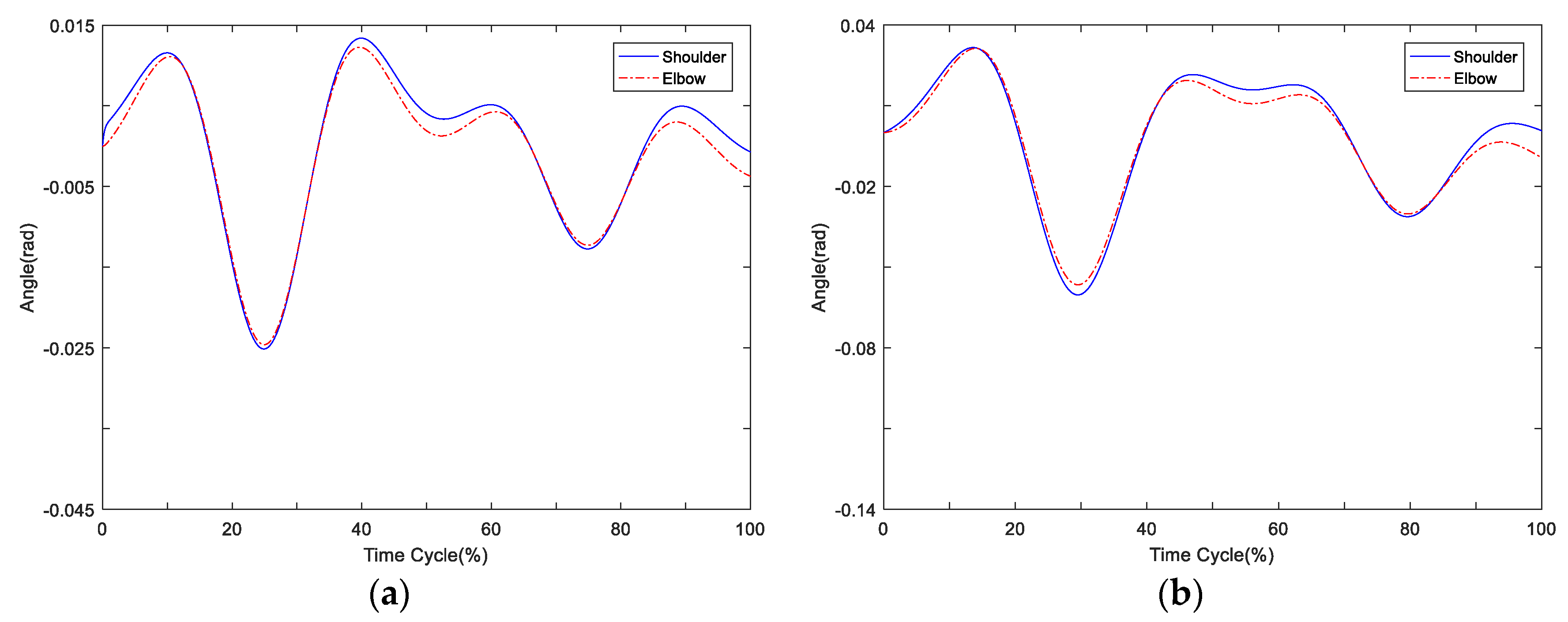
Table 2. The design parameters remained the same for both control methods, and the tracking errors for upper limb joints in the Mars and Moon gravity environments are shown in Figure 11.
From the two figures, the maximum tracking errors of upper limb joints in the three gravitational environments are shown in Table 3. Compared with the previous control method, the adaptive neural network control with fuzzy compensation had the following advantages: (1) a smaller tracking error, whereby the maximum tracking errors of upper limb joints were less than 0.05 rad in the three gravitational environments; (2) good adaptive ability to the gravity environment changes, whereby the tracking error changes in the three gravitational environments are small; (3) fast convergence to 0, verifying the superiority of the proposed method.

6. Conclusions

This paper presented an adaptive neural network control with fuzzy compensation for an upper limb exoskeleton in an active spacesuit. First, we designed the mechanical structure of the upper limb exoskeleton according to the kinematic characteristics and the distribution of degrees of freedom in the low-gravity experimental frame. Then, by utilizing the fuzzy system, a resistance moment model was developed to approximate the actual resistance moment of the simulated spacesuit. Compared with RBFNN control based on the computational torque method, the superiority of the proposed control method was verified. In our future work, we will focus on the multi-order transition curves of resistance moment and incorporate the dead-zone effects into the control design of the joint-assisted exoskeleton.

Author Contributions

Conceptualization, Z.L. and Y.D.; methodology, Z.L.; software, Z.L.; validation, Z.L. and P.T.; formal analysis, Z.L.; investigation, Z.L. and P.T.; resources, Y.D.; data curation, Y.D.; writing—original draft preparation, Z.L.; writing—review and editing, Z.L. and Y.D.; visualization, Z.L. and P.T.; supervision, Y.D.; project administration, Y.D.; funding acquisition, Y.D. All authors have read and agreed to the published version of the manuscript.

Funding

This research was funded by the Aerospace Research Project of China under Grant No. 020202.

Data Availability Statement

Data available on request due to privacy. The data presented in this study are available on request from the corresponding author. The data are not publicly available due to the project funding requirement.

Acknowledgments

The authors would like to express their gratitude to EditSprings (https://www.editsprings.com/ (accessed on 6 December 2020)) for the expert linguistic services provided.

Conflicts of Interest

The authors declare no conflict of interest.

References

  1. Zhang, C.F.; Han, L.L. Preliminary study on lunar robot for manned lunar exploration. Manned Spacefl. 2019, 25, 1–11. [Google Scholar]
  2. Wang, X.D.; Wang, Z.; Li, H.; Wang, C.H. Research on method of extravehicular spacesuit joint torque measurement and modeling. Space Med. Med Eng. 2015, 28, 195–202. [Google Scholar]
  3. Thomas, K.S.; McMann, H.J. Apollo: Mankind starts the exploration of the Moon. In U.S. Spacesuits, 2nd ed.; Springer: New York, NY, USA, 2012; pp. 97–178. [Google Scholar]
  4. Gary, L.H. The origins and technology of the advanced extravehicular space suit. In Isis; American Astronautically Society: Chicago, IL, USA, 2001; pp. 18–45. [Google Scholar]
  5. Sim, Z.L. Development of a Mechanical Mounter Pressure Bio-Suit System for Planetary Exploration. Master’s Thesis, Massachusetts Institute of Technology, Cambridge, MA, USA, 2006; pp. 43–48. [Google Scholar]
  6. Judnick, D.; Newman, D.; Hoffman, J. Modeling and testing of a mechanical counter pressure bio-suit system. In Proceedings of the 37th SAE International Conference on Environmental Systems, Albuquerque, NM, USA, 10–13 July 2007; pp. 1–7. [Google Scholar]
  7. Ikema, K.; Gubarevich, A.V.; Odawara, O.A. A pneumatic joint for enhancement of spacesuit flexibility. J. Aerosp. Eng. 2012, 27, 347–353. [Google Scholar] [CrossRef]
  8. Liu, Q.L.; Liu, X.Y.; Li, M. Design and experiment of pleated isotensoid spacesuit soft joint. Acta Aeronaut. Astronaut. Sin. 2015, 36, 3868–3875. [Google Scholar]
  9. Wang, Z.W.; Cheng, P.; Xu, L.M. Coupling mechanism modeling and motion analysis of hard thigh-hip joint in space suit. Manned Spacefl. 2018, 24, 433–439. [Google Scholar]
  10. Zhou, M.L.; Hou, W.G.; Xu, S.H. Design and analysis of power assist elbow for EVA spacesuit. Appl. Mech. Mater. 2014, 577, 395–400. [Google Scholar] [CrossRef]
  11. Rea, R.; Beck, C.; Rovekamp, R.; Neuhaus, P.; Diftler, M. X1: A robotic exoskeleton for in-space countermeasures and dynamo-metry. In Proceedings of the AIAA SPACE Forum, San Diego, CA, USA, 10–13 September 2013; pp. 1–6. [Google Scholar]
  12. Gao, Z.Q. Joints Damping Torque Test of Extravehicular Activity Spacesuit Arm. Ph.D. Thesis, Harbin Institute of Technology, Harbin, China, 2007; pp. 63–68. [Google Scholar]
  13. Li, Z.Y.; Dai, Y.H.; Tang, P.; Shi, S.C.; Huang, B. Hysteresis modeling and dynamic simulation of upper limb joints in lunar assist space suit. Manned Spacefl. 2019, 25, 440–447. [Google Scholar]
  14. Vantilt, J.; Tanghe, K.; Afschrift, M.; Bruijnes, A.K.; Junius, K.; Geeroms, J.; Aertbeliën, E.; De Groote, F.; Lefeber, D.; Jonkers, I.; et al. Model-based control for exoskeletons with series elastic actuators evaluated on sit-to-stand movements. J. Neuroeng. Rehabil. 2019, 16, 1–21. [Google Scholar] [CrossRef] [PubMed]
  15. Inel, F.; Carbone, G.; Ceccarelli, M. Design and implementation of high level control modes for a 3D cable-driven-parallel robot. Int. J. Mech. Control. 2020, 21, 87–94. [Google Scholar]
  16. Hamaya, M.; Matsubara, T.; Noda, T.; Teramae, T.; Morimoto, J. Learning assistive strategies for exoskeleton robots from user-robot physical interaction. Pattern Recognit. Lett. 2017, 99, 67–76. [Google Scholar] [CrossRef]
  17. Hou, Z.; Jin, S. Data-driven model-free adaptive control for a class of MIMO nonlinear discrete-time systems. IEEE Trans. Neural Netw. 2011, 22, 2173–2188. [Google Scholar] [PubMed]
  18. Feng, G. A compensating scheme for robot tracking based on neural networks. Robot. Auton. Syst. 1995, 15, 199–206. [Google Scholar] [CrossRef]
  19. Li, Z.; Huang, Z.; He, W.; Su, C.Y. Adaptive impedance control for an upper limb robotic exoskeleton using biological signals. IEEE Trans. Ind. Electron. 2017, 64, 1664–1674. [Google Scholar] [CrossRef]
  20. He, W.; Dong, Y. Adaptive fuzzy neural network control for a constrained robot using impedance learning. IEEE Trans. Neural Netw. Learn. Syst. 2018, 99, 1–13. [Google Scholar] [CrossRef] [PubMed]
  21. Lian, R.J. Intelligent controller for robotic motion control. IEEE Trans. Ind. Electron. 2011, 58, 5220–5230. [Google Scholar] [CrossRef]
  22. Zhao, M.; Xu, X.; Yang, H.; Pan, Z. Design of a predictive RBF compensation fuzzy PID controller for 3D laser scanning system. Appl. Sci. 2020, 10, 4662. [Google Scholar] [CrossRef]
  23. Kim, J.; Lee, G.; Heimgartner, R.; Revi, D.A.; Karavas, N.; Nathanson, D.; Galiana, I.; Eckert-Erdheim, A.; Murphy, P.; Perry, D.; et al. Reducing the metabolic rate of walking and running with a versatile, portable Exosuit. Science 2019, 365, 668–672. [Google Scholar] [CrossRef] [PubMed]
  24. Li, Z.; Dai, Y.; Hu, J.; Wang, J.; Tang, P. Design and analysis of joint-assisted exoskeleton control system of upper limb in active spacesuit. In Proceedings of the 39th Chinese Control Conference, Shenyang, Liaoning, China, 27–29 July 2020; pp. 3707–3712. [Google Scholar]
  25. Tang, K. Optimized Design of Structure of Upper-Limbs Exoskeleton Based on Finite Element Method. Master Thesis, University of Electronic Science and Technology of China, Chengdu, China, 2017; pp. 53–69. [Google Scholar]
  26. Matty, J. Results and analysis from space suit joint torque testing. In Proceedings of the 40th International Conference on Environmental Systems, Barcelona, Spain, 11–15 July 2010; pp. 1–6. [Google Scholar]
  27. Meyen, F.; Holschuh, B.; Kobrick, R.; Jacobs, S.; Newman, D. Robotic joint torque testing: A critical tool in the development of pressure suit mobility elements. In Proceedings of the 41st International Conference on Environmental Systems, Portland, OR, USA, 17–21 July 2011; pp. 1–6. [Google Scholar]
  28. Labiod, S.; Boucherit, M.S.; Guerra, T.M. Adaptive fuzzy control of a class of MIMO nonlinear systems. Fuzzy Sets Syst. 2005, 151, 59–77. [Google Scholar] [CrossRef]
  29. Yoo, B.K.; Ham, W.C. Adaptive control of robot manipulators using fuzzy compensator. IEEE Trans. Fuzzy Syst. 2000, 8, 186–199. [Google Scholar]
  30. Li, Z.; Wang, J.; Yan, S.; Hao, P.; Tang, P.; Dai, Y. Research on joint-assisted exoskeleton control system of lower extremity in active spacesuit. In Proceedings of the 2019 IEEE International Conference on Mechatronics and Automation, Tianjin, China, 4–7 August 2019; pp. 1889–1894. [Google Scholar]
  31. Inertial Parameters of Adult Human Body, Chinese Standard, GB/T 17245-2004. pp. 1–8. Available online: http://www.cssn.net.cn/cssn/front/6533160.html (accessed on 3 February 2021).
Figure 1. The suspended low-gravity experimental frame.
Electronics 10 00638 g001
Figure 2. The overall mechanical structure of upper limb exoskeleton.
Electronics 10 00638 g002
Figure 3. The resistance moment of upper limb joints: (a) shoulder joint; (b) elbow joint.
Electronics 10 00638 g003
Figure 4. The time–angle (resistance moment) description of first-order transition curves: (a) shoulder joint; (b) elbow joint.
Electronics 10 00638 g004
Figure 5. The resistance moment model.
Electronics 10 00638 g005
Figure 6. The time–resistance moment curves of upper limb joints: (a) shoulder joint; (b) elbow joint.
Electronics 10 00638 g006
Figure 7. The schematic diagram of the overall control system.
Electronics 10 00638 g007
Figure 8. The exoskeleton experimental platform.
Electronics 10 00638 g008
Figure 9. The real-time simulation system.
Electronics 10 00638 g009
Figure 10. The tracking errors for upper limb joints: (a) adaptive neural network control with fuzzy compensation; (b) radial basis function neural network (RBFNN) control based on computational torque method.
Electronics 10 00638 g010
Figure 11. The tracking errors for upper limb joints: (a) adaptive neural network control with fuzzy compensation in Mars gravity; (b) RBFNN control based on computational torque method in Mars gravity; (c) adaptive neural network control with fuzzy compensation in Moon gravity; (d) RBFNN control based on computational torque method in Moon gravity.
Electronics 10 00638 g011
Table 1. The degree of freedom (DoF) configuration and movement form scheme.
JointFlexion/ExtensionAbduction/Adduction
Shoulder joint1/Active1/Driven
Elbow joint1/Active0
Table 2. The bob-weight scheme of a single arm.
Body Segment Relative WeightWeightBob-Weight
Upper arm2.43%2.72 kg1.81 kg 1/2.27 kg 2
Forearm 1.25%1.4 kg0.93 kg 1/1.17 kg 2
1 Mars gravity; 2 Moon gravity.
Table 3. The maximum tracking errors in the three gravitational environments.
Control MethodJointEarth GravityMars GravityMoon Gravity
Adaptive neural network control with fuzzy compensationShoulder 0.0251 rad0.0327 rad0.0362 rad
Elbow 0.0246 rad0.0354 rad0.0415 rad
RBFNN control based on computational torque methodShoulder 0.0603 rad0.0951 rad0.1039 rad
Elbow 0.0565 rad0.1075 rad0.1207 rad
Publisher’s Note: MDPI stays neutral with regard to jurisdictional claims in published maps and institutional affiliations.

