1. Introduction
According to the International Federation of Robotics (IFR), in demand operations for industrial robots include handling applications, welding and assembly, with the first being the most sought after one [
1]. Material handling makes extensive use of the robot’s simple capability to transport objects using an appropriate end-of-arm tool (e.g., gripper), the robot can efficiently and accurately move products from one place to another. That is, if a precise location and orientation is given. However, due to fluctuating raw material prices, labour constraints, transportation/logistics, and the idiosyncrasy of clients, most industries are heavily influenced by agile production. Such production systems demand intelligent robots equipped with smart machine vision systems capable of fast and invariant object recognition applied to usage in unstructured environments. However, when applying artificial intelligence techniques to the area of industrial robots there are still challenges to overcome. As mentioned in [
2], these challenges include the successful learning of complex dynamics; control policies that work in dynamic, unstructured environments; manipulation; and advanced object recognition. Intelligent robots should be capable of recognising the part to grasp quickly and accurately to rapidly reconfigure itself on-line and improve production times.
The artificial vision system presented in this article aims to contributes to the development of intelligent robots via digital machine (characterised by reconfigurable hardware (FPGA) and an RISC processor to extract characteristics) integration. The RISC processor would help us extract characteristics and form a descriptive vector that in conjunction with Artificial Neural Networks (ANN’s), is in charge of the classification of parts through the BOF descriptor (Boundary Object Function) as originally described in [
3]. This object descriptor is used to predict the recognition of work-pieces using the FuzzyARTMAP [
4] (FAM) Neural Network learning mechanism (implemented in the FPGA). The embedded system optimises resources, improves computing speed and provides a fast determination of the object’s POSE.
The BOF descriptive vector is used for its invariability to scaling, rotation, translation, and its ability to describe the work-pieces with the same amount of data, so that, its vector length is always the same. In comparison, other methods based on feature extraction such as SIFT, SURF or ORB, rely on the number of points of interest and are scene dependent. The domain of recognition of the described approach is constrained to rigid objects and the following conditions: (1) The centroid should be contained within its solid surface for grasping, and (2) The generalisation capability of the ANN only considers previously learned objects. These conditions are easily met since most manufactured parts are regular, previously known objects.
Related Work and Original Contribution
Some of the most reliable descriptors that represent outlines of rigid shapes (silhouettes) are generated with tools/procedures such as Shape Number, where a unique number is used to identify the outline of a silhouette [
5]; Run Length Codes, which is a type of information compression where a string of equal data is replaced by a code that indicates the value and the number of times it occurs [
6]; and Chain Codes, a tool that represents a path in two or three dimensions [
7]. They have a reasonable computational cost for offline applications, however, they are not intended for usage in embedded systems.
Additionally, there are several tools/procedures based on detection of characteristic points and their descriptors such being the case of SIFT [
8] and its version in FPGA [
9]. With the Bouris-SURF [
10], which is a variant of the SURF method [
11], a 640 × 480 pixel image is processed in 18 ms without object detection. Another modified procedure is the Flex-SURF [
12], which had processing times of 2.9 s for the detection of characteristic points and 4s for the calculation of the descriptor; to be noted are the remarkable saving times with BRAM. Another case is the HR-SURF [
13] which is used to process images in 335 ms while not excluding object detection. In [
14] improvement was presented which allowed 400 features to be detected in a 640 × 480 image at 6.36 ms. Implementations of the ORB method and some variants known as FAST, FAST + BRIEF and FAST + BRISK have also been utilised [
15] to result in 6.8 ms of processing time for a video frame. This last work makes interesting comparisons to the algorithm solution in software using a GPU (Jetson TK1), for which times of 13.8, 18.2 and 27.6 ms were obtained, respectively. Alternative approaches are based on the design of digital machines for ANN implementation on reconfigurable hardware such as the FuzzyARTMAP as described in [
16]. Early design of VLSI circuits based on adaptive resonance theory were reported in [
17]. Other methods such as convolutional neural networks (CNNs) have also been reported [
18]; support vector machines (SVM) [
19] and IoT approaches are also reported in [
20,
21]. Late developments in hardware have culminated with Dynamic Vision Sensors (DVSs) which provide a new strategy for representing real-time visual information as event-flows such as spike Neural Networks [
17]. Rapid approaches to asynchronous, neuromorphic DVSs have reported very short latency times for robotic control as reported in [
22] where pixel data is generated and transmitted asynchronously only from pixels with varying brightness. This allows latency to go as low as 2.2 ms when detecting a moving ball and it triggering a motor command for the goalie robot.
Compared to other approaches, our proposal provides a fast determination of the POSE of the object by optimising resources and improving computational speed. This is basically due to three main reasons: The use of FuzzyARTMAP’s fast incremental learning capability, the effective use of memory resources in the FPGA, and the robustness of the BOF algorithm. Furthermore, the BOF is calculated while the pixels of the image frames are being received, resulting in part recognition times (including the object’s centroid and its orientation angle) as low as 1.466 ms, which It is a lower value than the values reported in the literature. This timing was also made possible by efficient Block RAM (BRAM) memory management and the inherent parallel processing of the FPGA and the neural architecture. These advantages reinforce our aim to provide industrial robots with the ability to quickly recognise objects by using a robust, yet simple algorithm.
This paper is organised as follows: After a brief introduction, in
Section 3 the Boundary Object Function (BOF) and the classification process of the FuzzyARTMAP (FAM) are explained.
Section 4 introduces the embedded system architecture, the BOF extractor and the FAM classifier. In
Section 5, experiments and results are provided. Finally, in
Section 6, conclusions are given.
2. Experimental Test-Bed
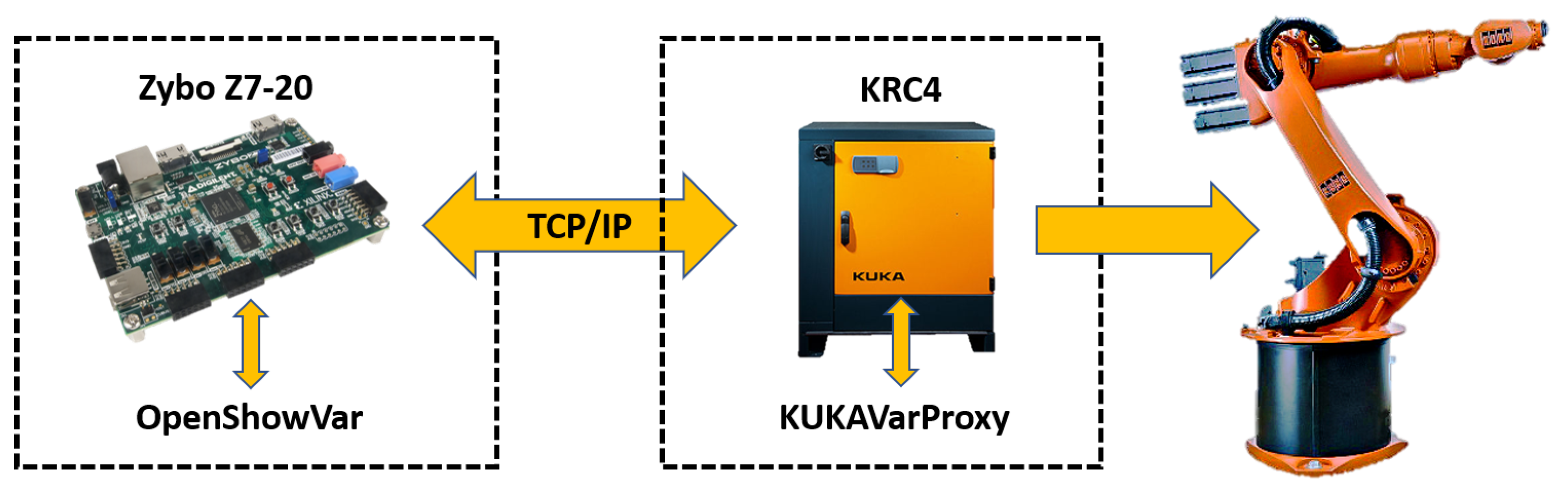
The experimental test-bed is integrated via a KUKA KR16 industrial robot equipped with a hand-in-eye camera. The communication framework was based on the open source KUKAVARPROXY server application as it is shown in
Figure 1. With this server application running in the robot controller, the read/write system and user-defined variables can be written. This framework allows full robot control that is translated to a Zybo Z7-20 module (Pullman, WA, USA). The Zybo Z7-20 is also used as a smart distributed module since it works as a TCP client and an interface to the KUKA Robot using OpenShowVar in a similar way to that described by [
23]. Lastly, the client application is programmed in Zybo Z7-20 to supervise the robotic system status.
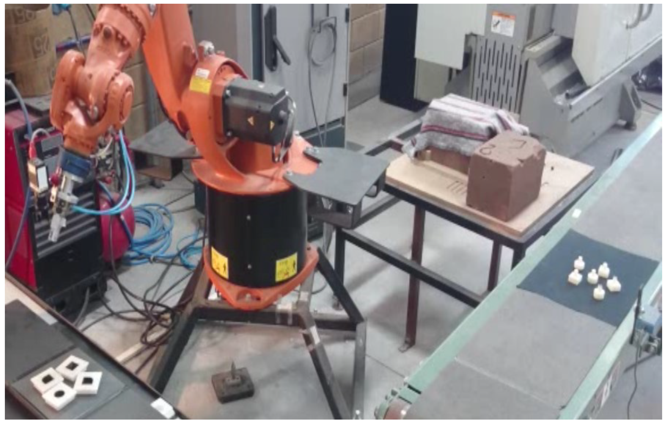
Additionally, the test-bed is comprised of a belt conveyor and a working table as shown in
Figure 2. The intention is to train the FuzzyARTMAP network with simple objects’ geometries so that the industrial robot may be able to grasp for further handling operations. In
Section 3, a comprehensive explanation of the BOF and the network’s training can be found.
3. The BOF Descriptor and the Fuzzy ARTMAP
This section addresses the method described in [
3] to generate the BOF vector descriptor. The FuzzyARTMAP ANN in charge of classifying the BOF vectors [
4] is also described. As explained earlier, the proposed methodology is intended for fast object recognition which requires the training of the FuzzyARTMAP to occur first; additionally, the training would have to happen offline and using sets of images from the work-pieces as input. This procedure was carried out with a Matlab script in an external computer. Once the training was completed, the object’s categorical representation was implemented in the Zybo Z7-20 module.
3.1. BOF
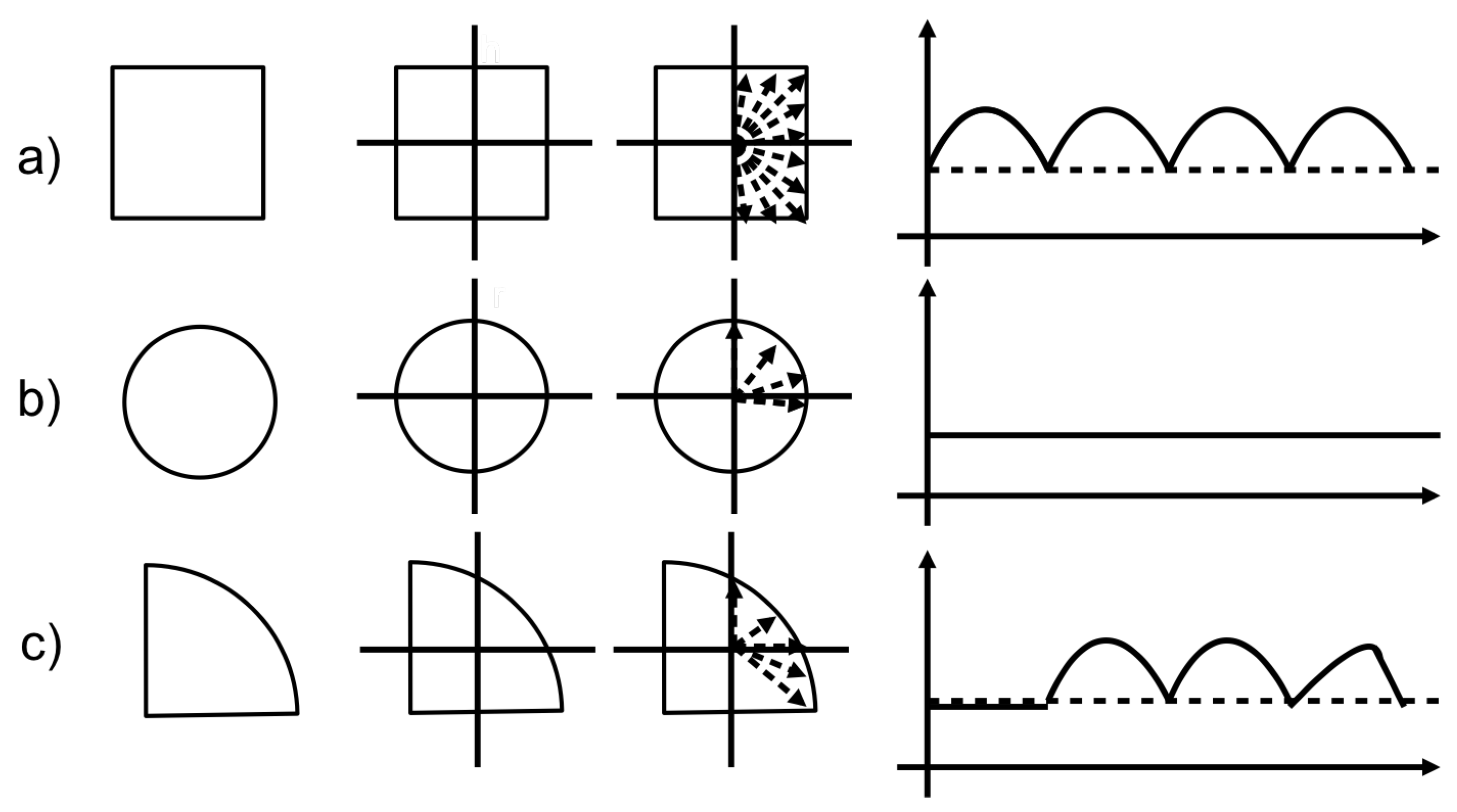
The BOF descriptor of an object is invariant to rotation, scaling, and translation, making it well suited for assembly and part-ordering applications. It is a representation of the contour of the object through a one-dimensional function, through the distance between the centroid of the body to each of the points that belong to the perimeter, and as a function of the angle as shown in
Figure 3.
The process begins when the objects are segmented from the scene and the Regions Of Interest (ROI) are formed. In this work, it is assumed that there is a single object in the scene. A previous process performs the ROI segmentation from the image, histogram equalisation, and background removal.
The algorithm for its extraction is as follows:
The region of interest is segmented from the original image and a new image is formed.
The image is converted into a binary image () from a threshold (). The background is assigned a logical ‘0’ and the object a logical ‘1’.
The centroid of the object is calculated with:
A two-dimensional arrangement known as a weight matrix is obtained
.
where:
;
;
;
;
.
The Boundary Points (BP) are obtained from two thresholds
and
.
The Euclidean distance between the centroid and each boundary point is calculated.
Each distance obtained in the previous step is normalised with the maximum distance between the centroid and a boundary point. The product from this process is the BOF vector.
3.2. Fuzzy ARTMAP
The Adaptive Resonance Theory (ART) developed by Stephen Grossberg at Boston University is a well-established, associative brain and competitive model. It was introduced as a theory of the human cognitive process. ART is applied and working in situations where it is called the stability-plasticity dilemma suggesting that connectionist models should be able to adapt and switch between its plastic and stable modes. That is, a system should exhibit plasticity to accommodate new information regarding unfamiliar events while still being able to remain in a stable condition if familiar or irrelevant information is being presented. The theory has evolved into many real-time architecture variants for unsupervised learning; the ART-1 algorithm for binary input patterns being one [
24]. Supervised learning is also possible through ARTMAP [
25] which uses two ART-1 modules capable of learning the correspondence between input patterns and desired output classes through training, this is the case seen in our research with the object’s representation. For analogue values, an appropriate ANN for supervised learning is the FuzzyARTMAP (FAM) [
4]. The learning process and subsequent selection of the BOF descriptor of an object are carried out through this network.
All objects to be recognised are learned by the FAM and represented categorically. Our research is focused on the classification of categories, that is, on the recognition of objects, however the learning is done off-line. The set of weights from all learned categories is transferred to the embedded system from a personal computer. It is important to mention that our BOF descriptor not only represent salient object features but also the manufactured part to be manipulated by the robot.
The procedure for FAM classification is as follows:
The input vector I uses the complement coding as given in Equation (
6).
a are the BOF elements where:
;
.
Activation
T is obtained from Equation (
7).
where the fuzzy AND, or intersection, operator ∧ is defined by
and the norm
is defined as
to any vector
p or
q with dimension M.
are the weight vector elements, where
,
,
> 0 and
.
The system is said to make a category choice when, at most, one F2 node can become active at a given time. The category choice is indexed by
J, where
were
T is the winner category. In case more than one
is maximal, the category
j with the smallest index is chosen. In particular, nodes become committed in order
. When the
Jth category is chosen,
and
for
.
Resonance occurs if the match function of the chosen category
J meets the vigilance criterion
given by Equation (
9).
were
. If Equation (
9) is not satisfied, the next category is chosen and
verified again. Mismatch reset occurs otherwise.
4. Embedded System Architecture
This section describes the architecture for the embedded system that integrates the digital machine for the extraction of the BOF descriptor and the digital machine for the FAM classifier, namely, the ES-BOF&FAM.
The electronic board used for design, testing and final implementation was the Zybo Z7-20 from Digilent. It contains the 7z020clg400-1 integrated circuit based on the Zynq-7000 family (AP SoC, Xilinx All Programmable System-on-Chip (San Jose, CA, USA)). The AP SoCs has a hybrid architecture that integrates an ARM Cortex-A9 processor (Cambridge, Cambs, UK), the Processing System (PS), and a Field Programmable Gate Array (FPGA) from the Xilinx 7-series(San Jose, CA, USA) family which acts as the Programmable Logic part. (PL). Viviado from Xilinx was used as a tool for the design, routing, synthesis, simulation and generation of the bitstream. The hardware description language to create the system in programmable logic (PL) was VHDL. Some IP modules ( Intellectual Property) designed by Xilinx were also integrated. For the programming and debugging of the algorithm that runs in the PS, Xilinx SDK and the C programming language were used.
The acquisition of video frames is carried out through a low-cost sensor, the OV7670 CCD (Santa Clara, CA, USA), with a maximum resolution of 640 × 480 pixels, a 1/6” lens and a frame rate of 30 fps in progressive mode. Pixels are sent to the ES-BOF&FAM through an 8-bit parallel port and the IC port for control and configuration.
Due to the parallelisation characteristics that FPGAs allow, some parts of the process, for the extraction of the BOF and for the classifier (the FAM network), were implemented in the PL of the Zynq chip. Other procedures are run on the PS taking advantage of specific algorithm libraries.
Processes such as communication and control of the video sensor; conversion of colour pixels to grayscale; image binarisation; histogram calculation; extraction of boundary points from the object; calculation of the object centroid, the orientation angle, distance; and the complement coding to conform the BOF vector are carried out in the FPGA. In the case of the FAM classifier, there is the modulus of the minimums of the inputs and weights. The accumulator and the multiplication of the factor is calculated offline.
The processes that are executed in the PS of the Zynq programmed in C are the highest-to-lowest sorting of the T; the integration of the weights of new categories to the FAM module; the main control of the system; the control and communication of the Ethernet network interface; those defined by commands for the control of the video sensor and, in general, the data management of the PL part. The algorithm for obtaining the ROI is performed by another method not addressed in this document.
4.1. General Architecture
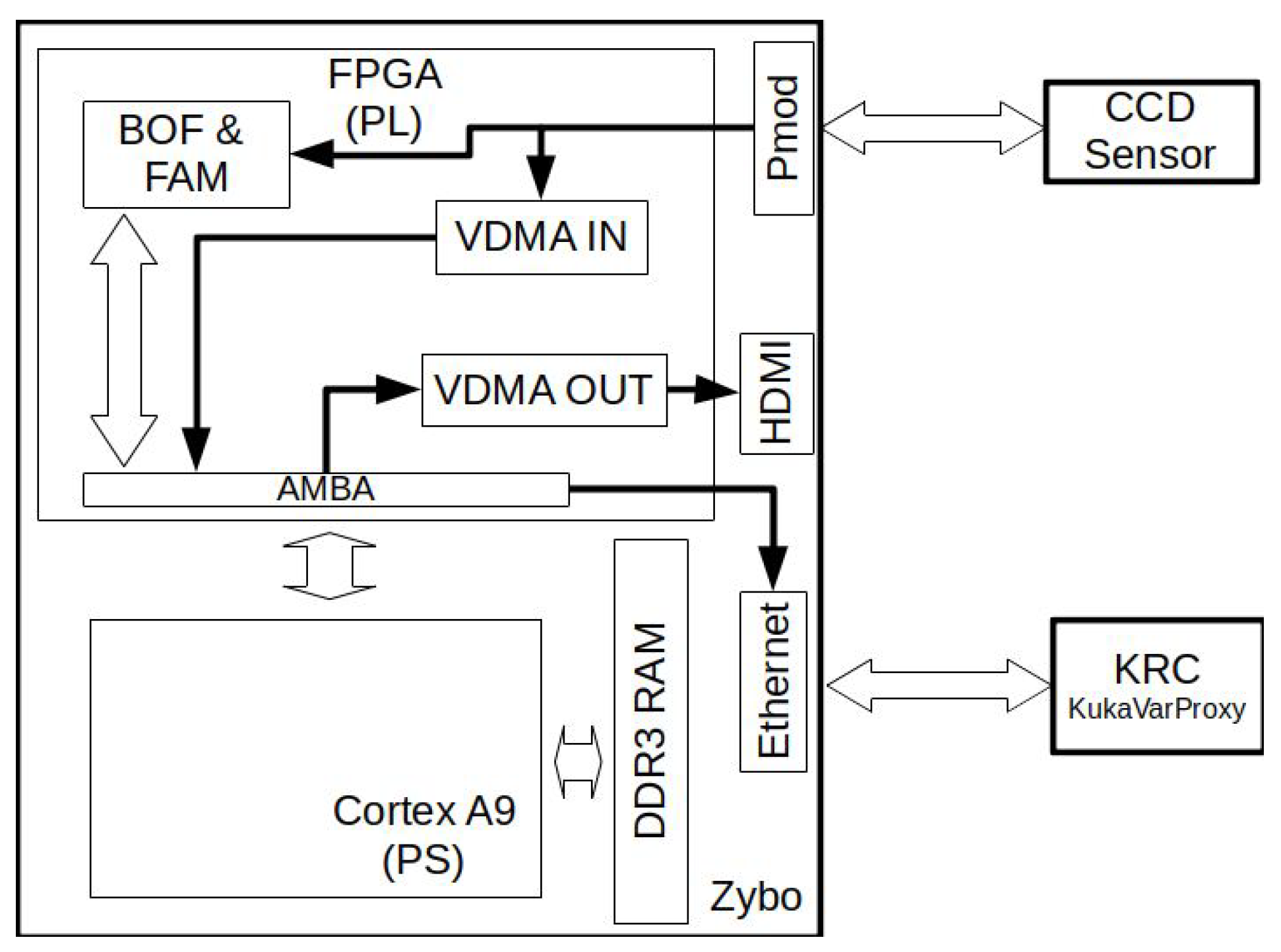
In the
Figure 4, the architecture of the embedded system is shown. The CCD sensor is connected to a PMOD port on the Zybo card via the GPIO pins. A client sends the data from the Ethernet interface to control the system parameters.
As mentioned earlier, the BOF descriptor and the FAM classifier are in the PL part of the Zynq and are connected via the AMBA bus ( Advanced Microcontroller Bus Architecture) to the PS. In particular, communication is carried out using the AXI4lite ( Advanced eXtensible Interface) standard; the reason for using AXI4lite being the amount of data to be transmitted as it does not warrant using another protocol for information burst messaging. Moreover, the CCD transmits the raw pixels to the BOF extractor, which transfers the information to the FAM classifier module.
4.2. Digital Machine for the BOF Extraction
To calculate the BOF, a pipeline process is carried out for each frame. In the first stage, the conversion from RGB to gray scale, the calculation of the histogram, and the determination of the binarisation threshold are carried out. In the second stage, the ROI is binarised and the centroid is calculated. In the third stage, the BOF is generated and stored. Starting from the fourth frame, the BOF is obtained in each subsequent frame.
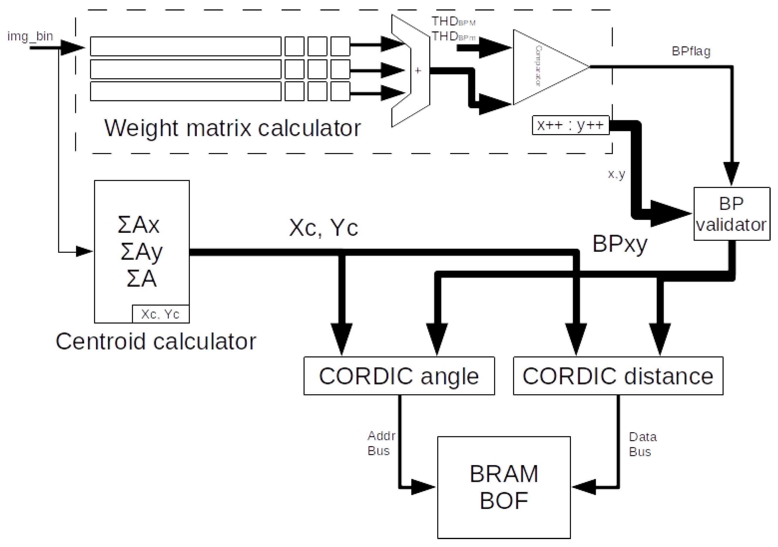
In
Figure 5, the digital machine for BOF extraction is shown. The input is the binary image of the object’s ROI and the output is the BOF vector. The BOF vector is stored in a BRAM (Block RAM) that is subsequently accessed from the FAM classifier module, although it can also be read from the PS.
4.2.1. Centroid Calculator
To obtain the
y
values for Equations (
1) and (
2), it is necessary to obtain the object’s area first. The area is calculated by increasing the variable sum_A by 1 each time clk_pixel changes while the object is in the scene, which is a condition verified by the WMC (Weight matrix calculator) module. Likewise, the
and the
values are calculated increasing its value
x and
y, respectively; where
x and
y are pointers along the ROI.
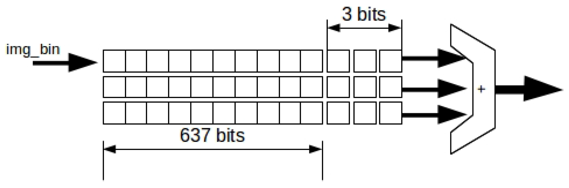
4.2.2. Boundary Points (BP) Extractor
In the third stage, I_WM is calculated according to Equation (
3). For this, we have the WM calculator shown in the
Figure 6. It is a combination of 3 shift registers (wmr_1, wmr_2 and wmr_3) (wmr is a weight matrix register) and a 4-bit parallel adder. The input to the module is img_bin and the output is a nibble in a range from 0 to 9. The size of each wmr is 1 bit and the width depends on the ROI. This is wmr_{1,2 y 3}
= ROI
. In order to know the maximum of the necessary resources after the synthesis, it is considered that the ROI width is equal to 640 pixels.
All elements of the three wmr registers are initialised with ‘0’. The first pixel in the image is placed at position wmr_1 (639). In the next cycle, the bits of wmr_1 are shifted one position to the right and so on until the first pixel of the image reaches the first position of the register, that is wmr_1 (0). In the next loop, wmr_1 (0) passes its value to the second register, wmr_2 (639). The same thing happens when wmr_2 (0) is reached and passed to wmr_3 (639).
When the first pixel of the image reaches the wmr_3 (0) register, a sum of the last 3 bits of the three wmr registers is performed. The BP of the object is obtained with the Equation (
4). This is done through a two-level comparator segmented by the thresholds THD_BPm and THD_BPM. Any pixel in img_wmr that matches this constraint is accepted as border. The values for THD_BPm and THD_BPM are determined to be 2 and 4, respectively. However, these values can be modified from the PS; we would modify the values because, in some cases, especially with small ROIs, it is necessary to reduce this margin. It should be noted that the value of nine in img_wmr represents a pixel that is exactly on the solid part of the object and a value less than 9 is close to the borders of the object.
The comparator’s output, BP_flag, is connected to the BP validator module, which determines if the coordinates x and y are a boundary point. To generate the coordinates x and y, two counters are used: coord_x that goes from 0 to ROI and coord_y that goes from 0 to ROI . The width depends on the concatenated value of the maximum of coord_x and coord_y for a maximum ROI, this is 10 bits for coordinates in x axis and 9 bits for coordinates in y axis.
4.2.3. BOF Vector Extraction
Each time a boundary point is detected, both the angle
and the distance
D (calculated with Equation (
5)) of the vectors [(Xc, Yc), (X
, Y
)] are calculated. This is precisely the information to be sent to the robot, the angle
and the centroid of the part to be grasped. In terms of HDL synthesis, the elements
and
are implemented directly with basic arithmetic operations. To obtain the angle
and the square root of (
5), the CORDIC method was used, which has already been implemented in reconfigurable hardware with a low error rate [
26].
Each element of the BOF vector is stored according to the corresponding position in its angle, that is, the element that corresponds to the angle, corresponds to the first direction of BRAM_BOF. The distance between the centroid and the BP is what is stored in that location. Thus, in the first memory address, we have the easternmost vector of the object with respect to the image at .
It was found that 180 elements making up the BOF vector was enough for the recognition process [
3]. Hence, the BRAM_BOF contains 180 locations,
of range for each element of the BOF. Since there is a probability that there is more than one BP with a separation smaller than
, it is taken as a general rule that the last value is overwritten to the previous one.
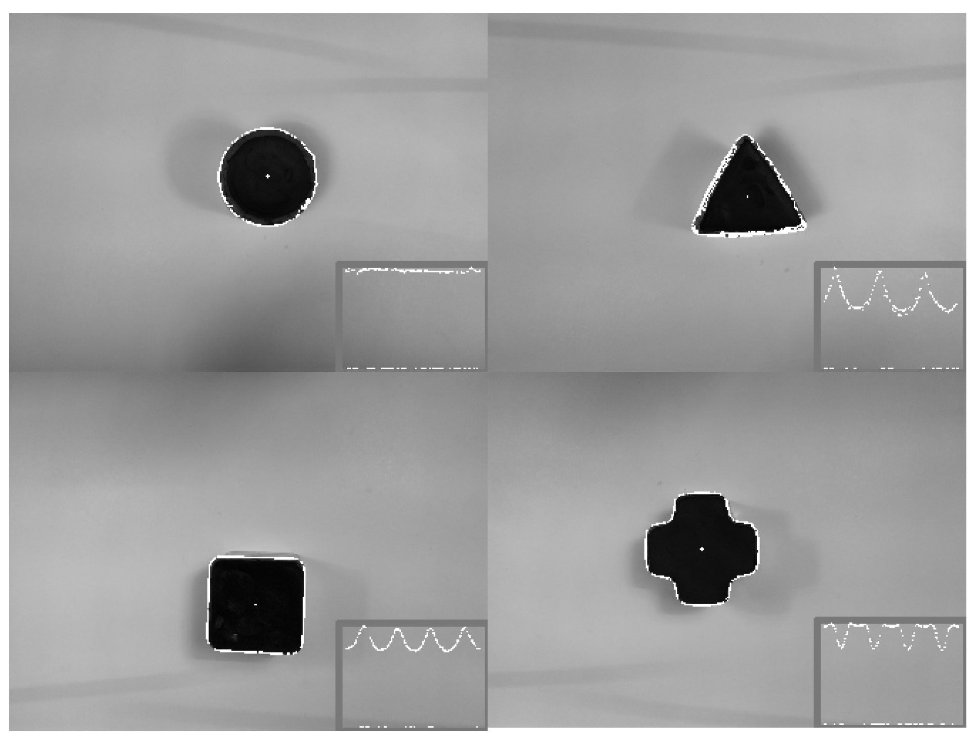
BOF values are normalised using the BOF max. This value is obtained by comparing the elements of the vector one by one with the last largest one. The
Figure 7 shows 4 objects with their centroid and BP superimposed. In addition to their corresponding BOF, all of them are obtained by the digital BOF extraction machine.
It is necessary to choose a suitable number type in VHDL to consume less hardware resources and to obtain acceptable precision based on our specific application for object recognition in the robot’s workspace. In ref. [
27], it is stated that floating point is more accurate for ANN calculations; however, more hardware resources are unnecessary if we consider the ROI corresponding to the workspace (object to be recognised). As mentioned, the spatial resolution of the camera was 640 × 480 pixels and in practice it would never be necessary to use this resolution for the workpiece. Therefore, it was considered appropriate to work with a spatial resolution of up to 80%, of that resolution, which corresponds to 512 pixels for the ROI. This value was also considered as the maximum distance value to be processed whereas the minimum value would be
which corresponds to 0.000000001 in base 2. This value can be represented by 9-bit fixed point and guarantee the best performance and resource usage for the FAM classification.
4.3. Digital Machine of the FAM Classifier
The BOF uses complement coding according to the Equation (
6). Since the learning of the FAM is made offline, the weight vector W for each category T
is initialised from the PS program. Either way, the weight vectors can be modified while the system is running, especially when there is a new category, although the total number of classifier structures are fixed from the biststream load to the PL.
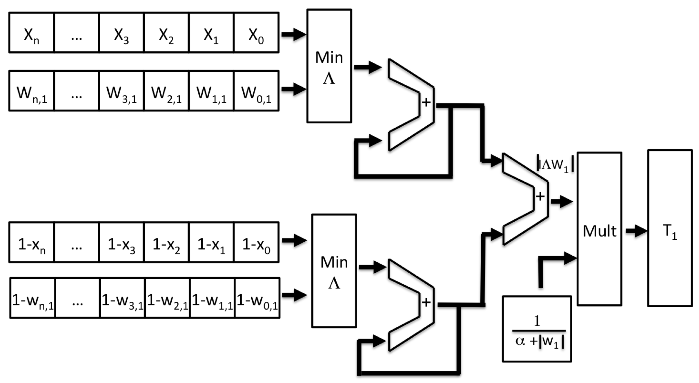
Figure 8 shows the architecture of the FAM classifier corresponding to a single category as given by Equation (
7). The inputs X in this case, the BOF to be recognised, the weights and its complement vector are divided into two groups to make the fuzzy minimum comparison “∧” faster. Thus, the inputs and the weights are compared by the Min_∧ module. Simultaneously, the complement of both vectors (the input one and the weights) are compared by a module identical to Min_∧. The length of the
n inputs is the size of the BOF vector, 180.
In each cycle, a pair of vector elements are processed and accumulated with the last pair. At first, the adder’s feedback “+” is set to zero. After 180 clock cycles, the equation is completed.
The factor is calculated offline and registers on the PL. As mentioned, it is also accessible from the PS. In another module, also implemented in VHDL, the previous factor is multiplied by which corresponds to the category T.
T
corresponds to a single object learned by the FAM ANN. Thus, for the recognition of more objects, as many T
as desired are required. One of the advantages of using reconfigurable hardware is the possibility of generating one or more instances of any entity, provided there are free resources in the FPGA. The
Figure 9 shows multiple FuzzyARTMAP classifiers corresponding to each learned object.
When all the T
have finished calculating, they are stored in several registers in the PL, which are accessed from the PS by a program that sorts them from highest to lowest using the bubble algorithm. Thus, the term T
is obtained from the Equation (
8) which corresponds to a possible winning category.
To corroborate the above,
of the Equation (
9) must be satisfied. The upper term has already been calculated, however the lower term
is calculated with a sequential accumulator every time we have a new element of BOF. If it is not fulfilled, it is necessary to repeat this process with another T
.
4.4. The Processing System (PS)
The PS intervenes in most of the functions to read and write data between the different digital machines, acting as an orchestrator. It also performs the following tasks:
Configuration of ports with peripherals.
Configuration of digital machines for BOF; FAM and their parameters ; THD_BPm and THD_BPM; and others.
TCP/IP communication over the stack lwIP (lightweight IP) with other nodes for sending and receiving commands. This is achieved through sockets.
With an OpenShowVar implementation in C, one is able to send commands and receive status to/from the KUKA robot.
Asynchronous serial communication for program loading and algorithm debugging. This is only applicable to certain occasions.
Control of interruptions triggered by the socket.
Reading the registers T from the PL through the AXI4Lite protocol and later their sorting using the bubble algorithm.
Configuration of the VDMA IN and VDMA OUT blocks in case it is required to use them and they are included in the reconfigurable hardware.
Configuration and control of the CCD OV7670 (e.g., image equalisation).
5. Tests and Results
The tests to compare the time taken for each of the steps, both for the extraction of the BOF and the FAM classifier, are CPU A and CPU B. Both computers have a Intel Core i7 processor (Santa Clara, CA, USA)with different model (3610QM and 2600S) and 8 GB RAM. CPU A runs at 2.3 GHz while CPU B runs at 2.8 GHz. For both computers, the method was developed in two programming languages, C++ and Matlab. The C++ compiler version was gcc 4.9 and, for Matlab, version 18 was used.
The
Table 1 shows the time elapsed in each stage of the process for each platform, the two CPUs and the ES-BOF&FAM.
The test at the workstations was synchronised with a time measurement function. However, since the operating system uses the CPU extensively, the time obtained averaged over 1000 iterations. In addition, to lessen the effect of the operating system on the test, GNU/Linux was used since it is more likely to reduce the number of unnecessary processes at the time of the experiment.
Regarding what was implemented in the FPGA, the time measurement was performed in each stage by counting the number of clock cycles between the frequency of the main clock. This clock is 50 MHz, a value that depends on the speed of the pixel capture for the CCD sensor. However, the classification runs at 125 MHz.
The tests were carried out using the same image captured by the CCD sensor with a resolution of 640 × 480 pixels. A copy of this image was transmitted to the two CPUs. The used libraries are: OpenCV for C++ to load and process the image and the Graphics library for Matlab. In both cases, the image is stored in RAM. In contrast, the ES-BOF&FAM does not store any data in the RAM of the PS, nor in a BRAM of the PL; the processing is online, so that the capture of video frames is ahead one clock cycle to the calculation of the BP and the centroid. The difference between the performance of both CPUs, whether in C++ or Matlab, is very small. While it is observed that what was developed in C++ ends earlier than in Matlab. Note that the total elapsed time for object recognition in ES-BOF & FAM is less than a fourth part of the elapsed time using any CPU running the C++ program.
With the 15 objects shown in
Figure 10, the ES-BOF&FAM was proven from which the mean of the MSE (Mean Squared Error) between results from ES-BOF & FAM and from the CPU with Matlab was 0.0042
. The logic resources are indicated in
Table 2; here, it is shown that 9.09% of LUTs and 36.07% of available BRAM was used for the PL of the XC7Z010-1CLG400C. This utilisation includes raw image processing, BOF extractor (BOF module), and 100 FAM classifiers (100 objects). In order to figure out the amount of resources in case the FAM classifier increases, three iterations with 20, 100 and 200 FAM classifiers were calculated.
The orchestrator code uses 0.19% of the ZYBO’s RAM (DDR 512 MB). It should be noted that the PS RAM is not used to store temporary data for image processing or the FAM classifier; this is done in the PL. OpenCV, in C ++, uses approximately 3.7 MB to store such an image. However, to calculate the I_WM, the PL only requires 3 BRAMs of 640 by 1 bit wide. This represents 0.7% of ZYBO’s total BRAM.
In terms of the use of detectors, it is important to make a comparison with detectors such as SURF + BRIEF and the one presented in this work. These detectors are similar to the BOF, in terms that they are used for feature detection in object recognition tasks. In comparison, the BOF encodes on its own the object description.
Table 3 shows a comparison between the performance of a SIFT-based and SURF-based method for object detection implemented in FPGA + CPU and the one presented in this work.
General aspects to highlight in
Table 3 is the use of less logic resources as follows:
Registers: 3876 compared with 23,700 in [
28] and 8238 in [
14] for only 5 categories.
DSP: 15% usage compared to 28% in [
14] and 100% in [
28]
BRAM: 36% usage compared to 46% in [
28] and in comparison up to 91% in [
14]
Also, our solution does not use the PS RAM to process data. In ref. [
14], the performance to detect characteristic points and calculate their descriptors is presented. However, it does not include the match and recognition time. Another advantage in our approach is that more information is obtained in a single step, such as the centroid of the object and the angle of rotation. In other cases, this information would still have to be obtained, increasing latency and overall processing time during object recognition for robot tasks.
6. Conclusions
The speed process has been faster with the Zybo Z7-20 module using software and digital machines, compared to the algorithm implemented in an ordinary computer. In the embedded system, the whole process takes a fourth the time spent on a computer with the same algorithm developed in C++. It is easy to observe that there is a big difference between the time required to calculate the distances D and the angle in the ES-BOF & FAM compared to the time for those same actions in the CPU. This time could even be shortened if a CCD sensor with higher capture rate were used. In terms of computational resources, the use of the RAM in the CPU for this method is not efficient because, in the best case, each video frame is stored only once and the space is overwritten in each processing step requiring 3.7 MB. In comparison, the only data stored temporarily in our BOF method is in the PL and it only needs 3 × 640 × 1 bit of BRAM type memory. The communication framework with an industrial robot controller was tested, the robot responded to motion commands by moving the arm onto the respective object according to its centroid values. The gripper can be oriented for grasping purposes taking the orientation angle as a reference. The results presented in this paper were focused on the fast extraction of these parameters as well as the object learning through the BOF learning. The object’s centroid and boundary points were calculated while acquiring the progressive image frame; all that was done with the intention of readying it for neural processing. The remaining time was devoted to recognise the object, which was always achieved with learning times as low as 1.466 ms which is rather encouraging for real-time applications with robots.
Multimodal learning processing will require smart robots to respond within the human average response time, about 200 ms, for a safe operation. In this regard, new collaborative robots in the shop floor would demand an increased capability to work with human operators in multimodal scenarios where vision, auditory and somatosensory information would fuse for processing motor coordination actions within this time frame. The results in this paper are a step forward to this direction demonstrating that the hardware integration of the video sensor, image processing, descriptor generator and the ANN classifier can accomplish cognitive decisions on a single chip.


 ,
, 


