
A Multi-Objective Design Optimization for a Permanent Magnet Synchronous Machine with Hairpin Winding Intended for Transport Applications


Abstract
:1. Introduction
2. Preliminary Design Process
2.1. Assumptions and Constraints
- The diameter of the wheels must be ≥203.2 mm.
- The maximum power P required from the battery must not exceed 80 kW.
- The maximum allowed DC-link voltage VDC must not exceed 600 V.
- There are no limitations concerning the number and the type of electric motors.
2.2. Machine Sizing Equations
2.3. Power Losses
2.4. Power Density
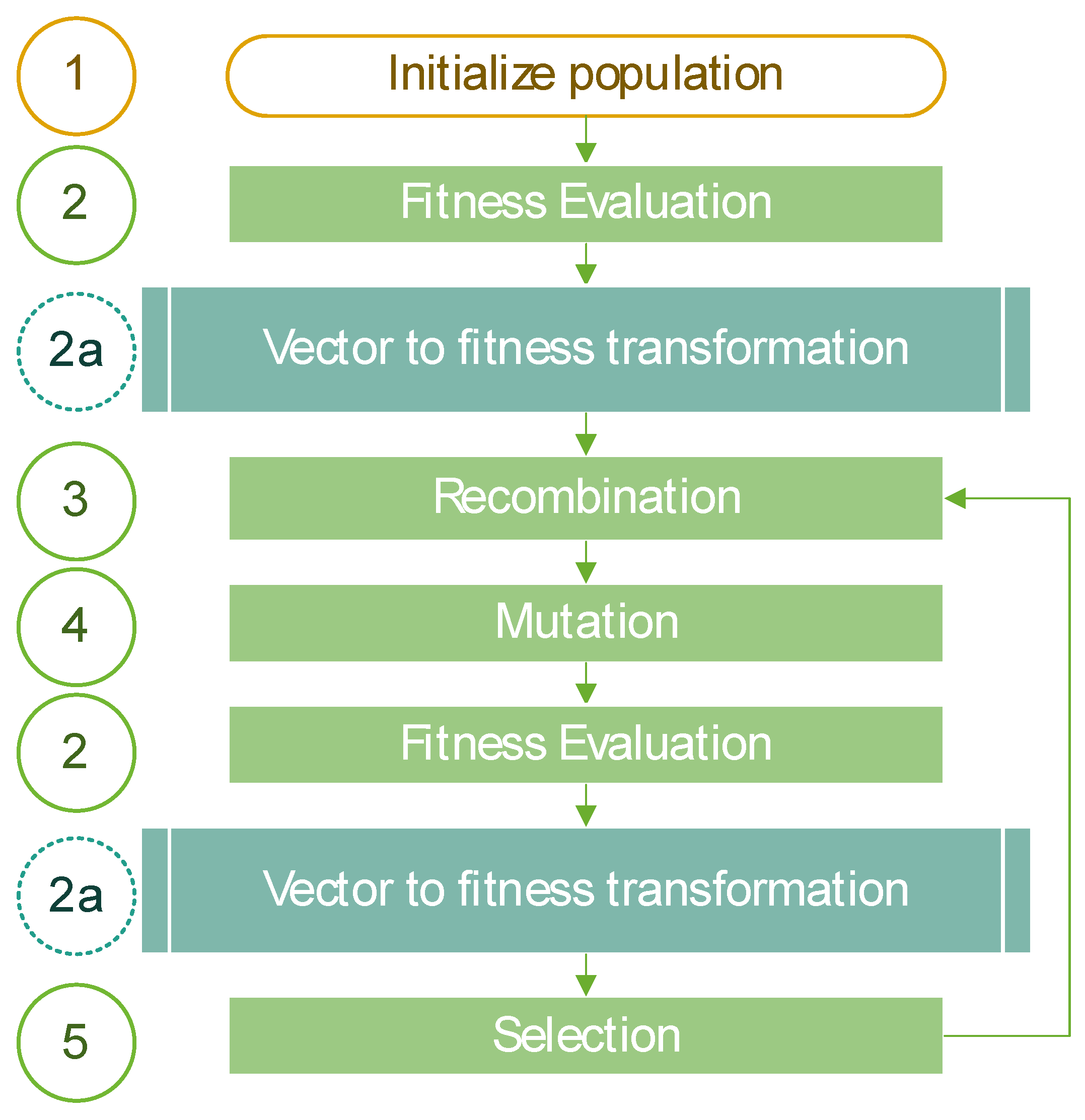
3. Optimization Process
4. Results
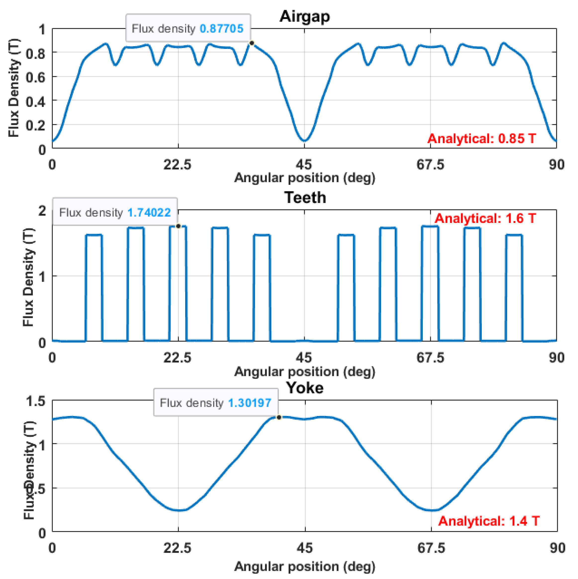
4.1. Preliminary Sensitivity Analysis and Validation of the Analytical Model
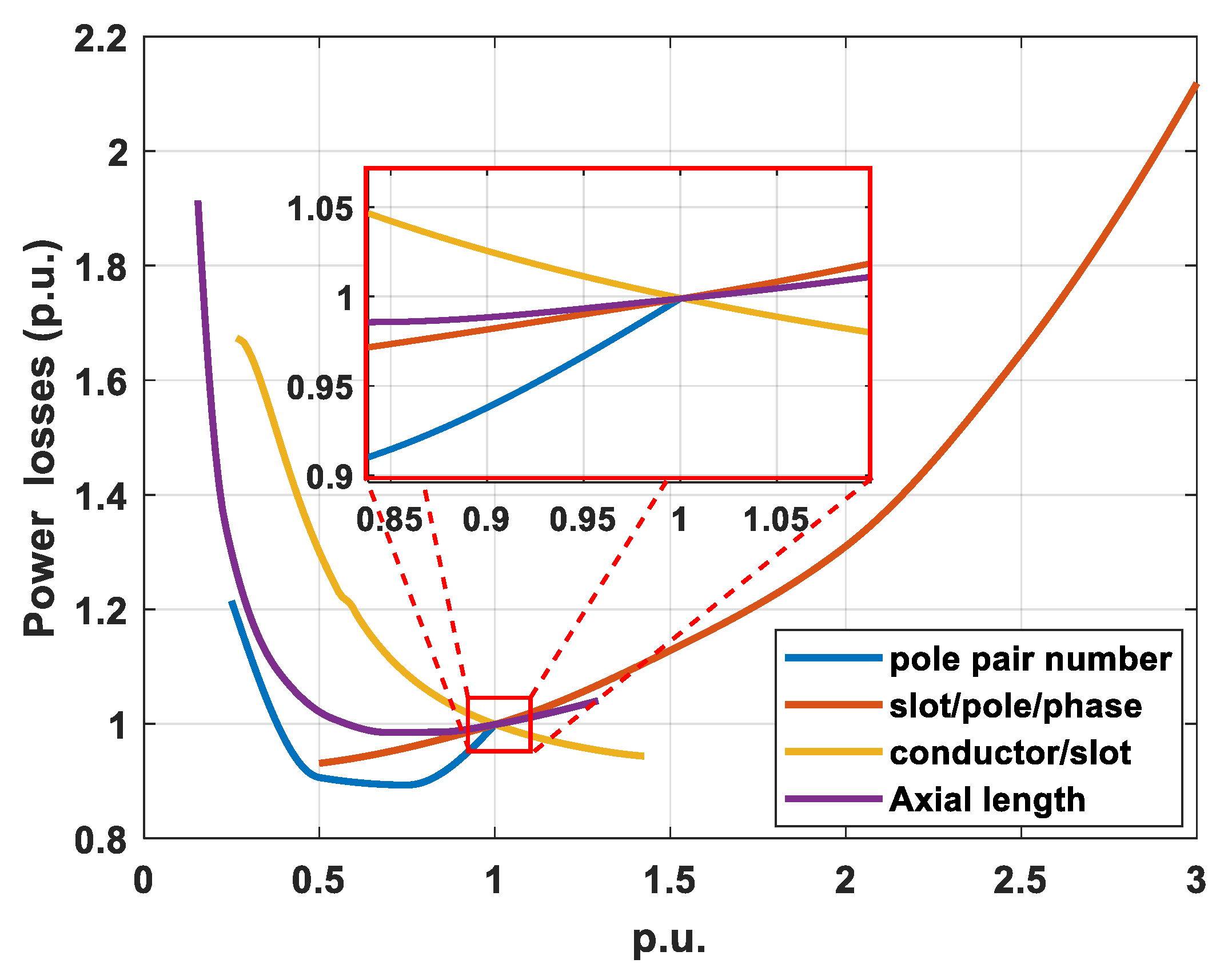
4.2. Effective Parameters
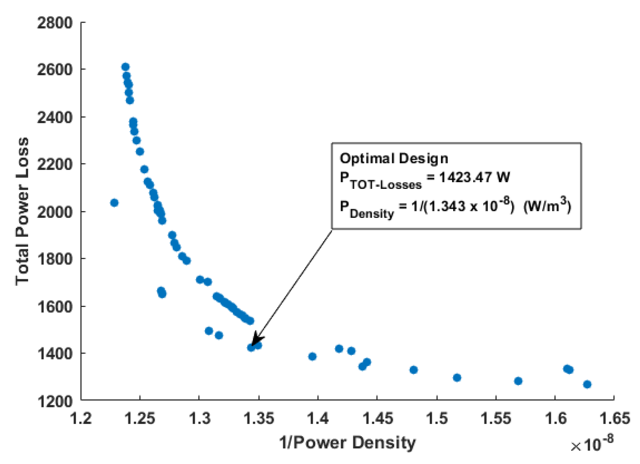
4.3. MOEA Results and Comparison
5. Conclusions
Author Contributions
Funding
Conflicts of Interest
References
- Zhao, Y.; Li, D.; Pei, T.; Qu, R. Overview of the rectangular wire windings AC electrical machine. CES Trans. Electr. Mach. Syst. 2019, 3, 160–169. [Google Scholar] [CrossRef]
- Arzillo, A.; Nuzzo, S.; Braglia, P.; Franceschini, G.; Barater, D.; Gerada, D.; Gerada, C. An Analytical Approach for the Design of Innovative Hairpin Winding Layouts. In Proceedings of the International Conference on Electrical Machines (ICEM), Gothenburg, Sweden, 23–26 August 2020; pp. 1534–1539. [Google Scholar]
- Nuzzo, S.; Barater, D.; Gerada, C.; Vai, P. Hairpin Windings: An Opportunity for Next-Generation E-Motors in Transportation. IEEE Ind. Electron. Mag. 2021, 2–10. [Google Scholar] [CrossRef]
- Islam, S.; Husain, I.; Ahmed, A.; Sathyan, A. Asymmetric Bar Winding for High-Speed Traction Electric Machines. IEEE Trans. Transp. Electrif. 2019, 6, 3–15. [Google Scholar] [CrossRef]
- Scuiller, F.; Zahr, H.; Semail, E. Maximum Reachable Torque, Power and Speed for Five-Phase SPM Machine With Low Armature Reaction. IEEE Trans. Energy Convers. 2016, 31, 959–969. [Google Scholar] [CrossRef]
- Soltani, M.; Nuzzo, S.; Barater, D.; Franceschini, G. Considerations on the Preliminary Sizing of Electrical Machines with Hairpin Windings. In Proceedings of the 2021 IEEE Workshop on Electrical Machines Design, Control and Diagnosis (WEMDCD), Modena, Italy, 8–9 April 2021; pp. 46–51. [Google Scholar]
- Popescu, M.; Goss, J.; Staton, D.A.; Hawkins, D.; Chong, Y.C.; Boglietti, A. Electrical Vehicles—Practical Solutions for Power Traction Motor Systems. IEEE Trans. Ind. Appl. 2018, 54, 2751–2762. [Google Scholar] [CrossRef] [Green Version]
- Sun, X.; Shi, Z.; Lei, G.; Guo, Y.; Zhu, J. Analysis and Design Optimization of a Permanent Magnet Synchronous Motor for a Campus Patrol Electric Vehicle. IEEE Trans. Veh. Technol. 2019, 68, 10535–10544. [Google Scholar] [CrossRef]
- Hernandez, O.S.; Morales-Caporal, R.; Rangel-Magdaleno, J.; Peregrina-Barreto, H.; Hernandez-Perez, J.N. Parameter Identification of PMSMs Using Experimental Measurements and a PSO Algorithm. IEEE Trans. Instrum. Meas. 2015, 64, 2146–2154. [Google Scholar] [CrossRef]
- Dang, L.; Bernard, N.; Bracikowski, N.; Berthiau, G. Design Optimization with Flux Weakening of High-Speed PMSM for Electrical Vehicle Considering the Driving Cycle. IEEE Trans. Ind. Electron. 2017, 64, 9834–9843. [Google Scholar] [CrossRef]
- Feng, G.; Lai, C.; Kar, N.C. An Analytical Solution to Optimal Stator Current Design for PMSM Torque Ripple Minimization With Minimal Machine Losses. IEEE Trans. Ind. Electron. 2017, 64, 7655–7665. [Google Scholar] [CrossRef]
- Zhao, W.; Wang, X.; Gerada, C.; Zhang, H.; Liu, C.; Wang, Y. Multi-Physics and Multi-Objective Optimization of a High Speed PMSM for High Performance Applications. IEEE Trans. Magn. 2018, 54, 1–5. [Google Scholar] [CrossRef]
- Jung, D.S.; Kim, Y.H.; Lee, U.H.; Lee, H.D. Optimum Design of the Electric Vehicle Traction Motor Using the Hairpin Winding. In Proceedings of the 2012 IEEE 75th Vehicular Technology Conference (VTC Spring), Yokohama, Japan, 6–9 May 2012. [Google Scholar] [CrossRef]
- Xue, S.; Michon, M.; Popescu, M.; Volpe, G. Optimisation of Hairpin Winding in Electric Traction Motor Applications. In Proceedings of the IEEE International Electric Machines & Drives Conference (IEMDC), Hartford, CT, USA, 17–20 May 2021; pp. 1–7. [Google Scholar] [CrossRef]
- Riviere, N.; Villani, M.; Popescu, M. Optimisation of a High Speed Copper Rotor Induction Motor for a Traction Application. In Proceedings of the IECON 2019—45th Annual Conference of the IEEE Industrial Electronics Society, Lisbon, Portugal, 14–17 October 2019; Volume 1, pp. 2720–2725. [Google Scholar] [CrossRef]
- Preci, E.; Gerada, D.; Degano, M.; Buticchi, G.; Gerada, C.; Nuzzo, S.; Barater, D. Hairpin Windings: Sensitivity Analysis and Guidelines to Reduce AC Losses. In Proceedings of the 2021 IEEE Workshop on Electrical Machines Design, Control and Diagnosis (WEMDCD), Modena, Italy, 8–9 April 2021; pp. 82–87. [Google Scholar] [CrossRef]
- Devito, G.; Nuzzo, S.; Barater, D.; Franceschini, G.; Papini, L.; Bolognesi, P. Design of the Propulsion System for a Formula SAE racing car based on a Brushless Motor. In Proceedings of the IEEE Workshop on Electrical Machines Design, Control and Diagnosis (WEMDCD), Modenta, Italy, 8–9 April 2021; pp. 318–324. [Google Scholar]
- Formula SAE Rules 2021 Version 1.0. Available online: www.fsaeonline.com/cdsweb/gen/DocumentResources.aspx (accessed on 19 November 2021).
- Pyrhonen, J.; Jokinen, T.; Hrabovcova, V. Design of Rotating Electrical Machines; John Wiley & Sons Ltd.: Chichester, UK, 2013. [Google Scholar]
- Coello, C.A.C.; Lamont, B.G.; Van Veldhuizen, A. Evolutionary Algorithms for Solving Multi-Objective Problems; Springer: New York, NY, USA, 2007; Volume 5. [Google Scholar]


| Parameter | Condition |
|---|---|
| Motor topology | Surface-mounted PM |
| Motor’s location | Rear-axle |
| Maximum torque to wheels | 600 Nm |
| Reduction ratio | 10 |
| Motor rated torque | 30 Nm |
| Base speed | 12,740 rpm |
| Parameter | Value |
|---|---|
| Mechanical power P | 40 kW |
| Line-to-line Voltage V | 540 V |
| Surface current density J | 13 A/mm2 |
| Airgap flux density Bag | 0.85 T |
| Maximum tooth flux density Bt | 1.6 T |
| Maximum yoke flux density By | 1.4 T |
| Linear current density A | 70 A/mm |
| Targeted efficiency | 95% |
| Parameter | Value |
|---|---|
| Core material | M330-50A |
| PM material | N28AH |
| Cooling system | Natural convention |
| Stator winding | Distributed, full-pitch, single layer |
| Parameter | Symbol |
| Fill factor | kff |
| Outer rotor diameter [mm] | D |
| Axial length [mm] | L |
| PM span [deg] | αPM |
| Number of phases | m |
| Number of slots-per-pole-per-phase | q |
| Pole pair number | p |
| Parameters | Round Winding | Hairpin 1st Design | Hairpin Optimal Design | Improvement |
|---|---|---|---|---|
| pole number | 6 | 8 | 8 | - |
| slot/pole/phase | 1 | 2 | 4 | - |
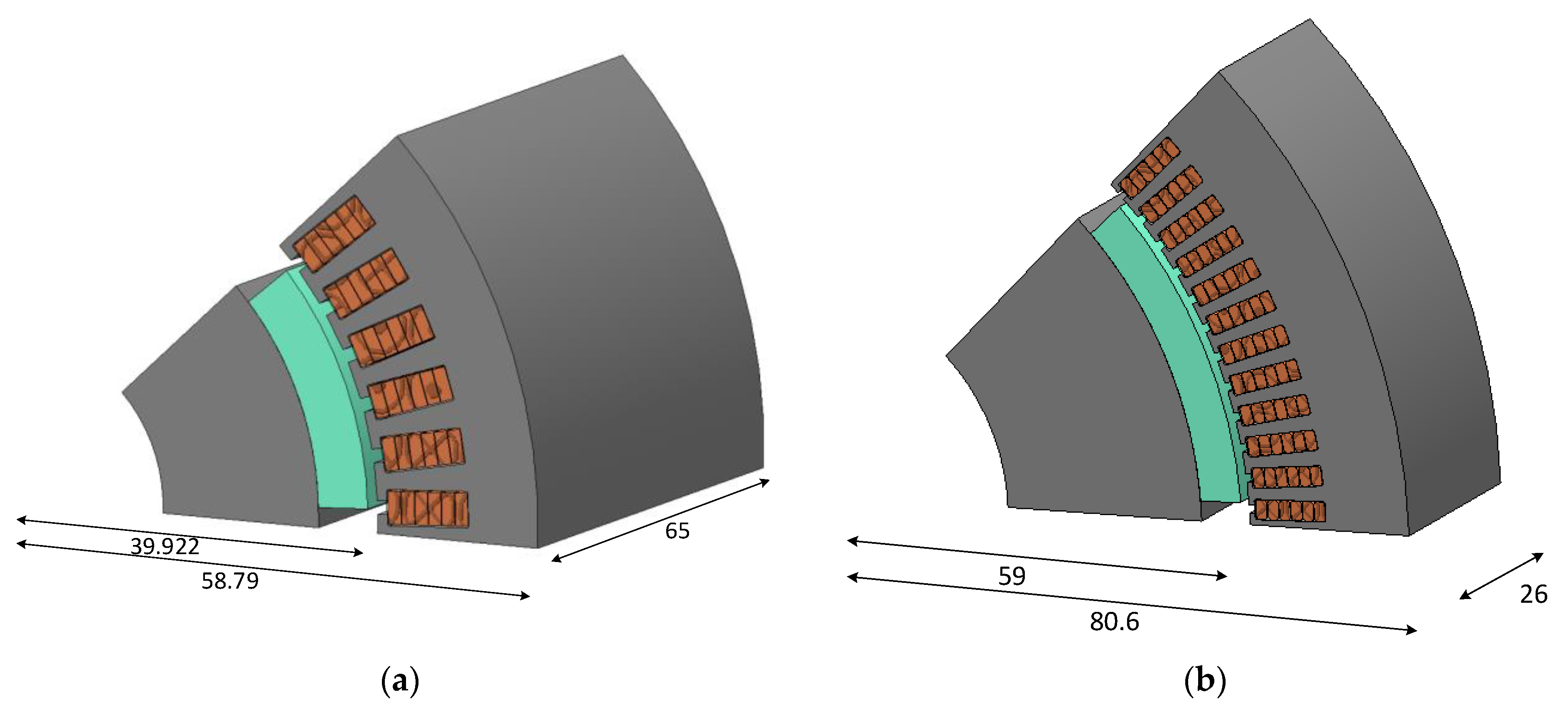
| axial length | 65 | 65 | 26 | - |
| conductors/slot | 11 | 6 | 6 | - |
| rotor radius | 45 | 39.922 | 59 | - |
| Tooth width | 10 | 2 | 1.635 | - |
| Yoke thickness | 14 | 7.7 | 13.35 | - |
| outer radius | 85 | 58.79 | 80.6 | - |
| Fill factor | 60% | 85% | 85% | - |
| Peak current (A) | 140 | 80.56 | 63.7 | - |
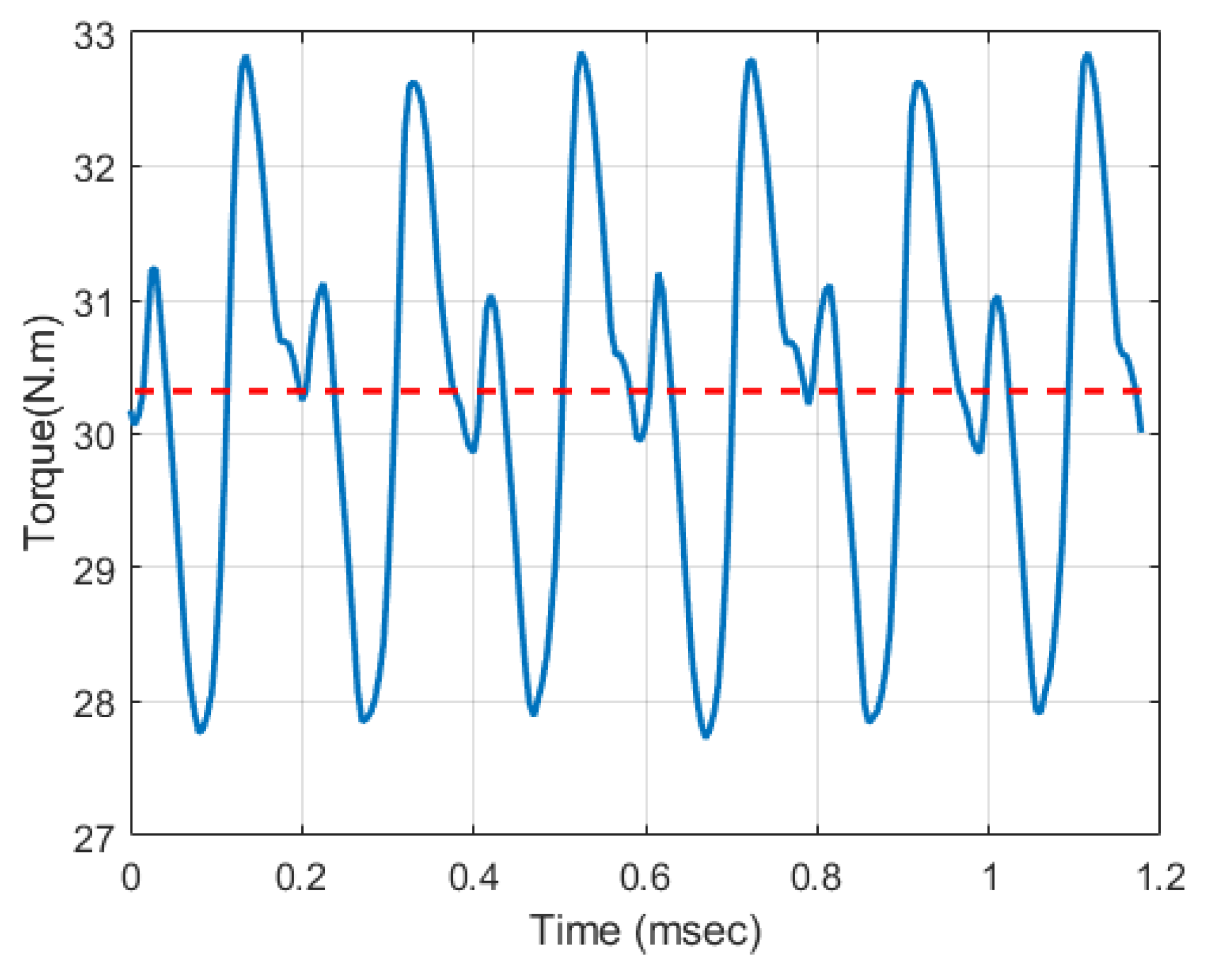
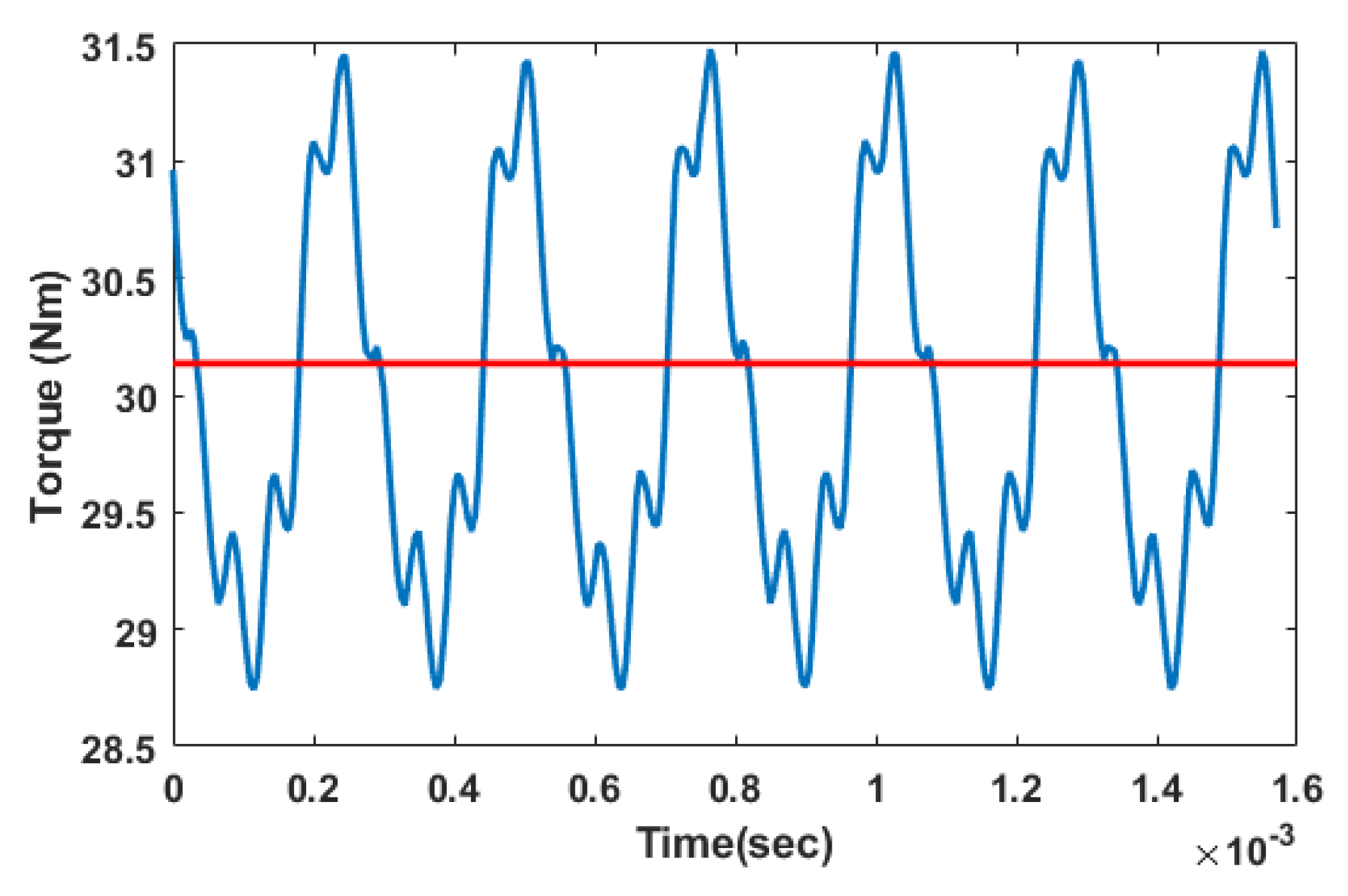
| Torque ripple (%) | 16% | 17% | 8.97% | 9.03% |
| Power loss (kW) | 2 | 1.47 | 1.42 | 10.55%, |
| Efficiency | 95.2% | 96.45% | 96.6% | 0.15% |
| volume power density (MW/m3) | 16.75 | 67.3 | 74.4 | 12.3% |
| volume torque density (kNm/m3) | 13.21 | 49.65 | 55.76 | 3.4% |
Publisher’s Note: MDPI stays neutral with regard to jurisdictional claims in published maps and institutional affiliations. |
© 2021 by the authors. Licensee MDPI, Basel, Switzerland. This article is an open access article distributed under the terms and conditions of the Creative Commons Attribution (CC BY) license (https://creativecommons.org/licenses/by/4.0/).
Share and Cite
Soltani, M.; Nuzzo, S.; Barater, D.; Franceschini, G. A Multi-Objective Design Optimization for a Permanent Magnet Synchronous Machine with Hairpin Winding Intended for Transport Applications. Electronics 2021, 10, 3162. https://doi.org/10.3390/electronics10243162
Soltani M, Nuzzo S, Barater D, Franceschini G. A Multi-Objective Design Optimization for a Permanent Magnet Synchronous Machine with Hairpin Winding Intended for Transport Applications. Electronics. 2021; 10(24):3162. https://doi.org/10.3390/electronics10243162
Chicago/Turabian StyleSoltani, Mohammad, Stefano Nuzzo, Davide Barater, and Giovanni Franceschini. 2021. "A Multi-Objective Design Optimization for a Permanent Magnet Synchronous Machine with Hairpin Winding Intended for Transport Applications" Electronics 10, no. 24: 3162. https://doi.org/10.3390/electronics10243162
APA StyleSoltani, M., Nuzzo, S., Barater, D., & Franceschini, G. (2021). A Multi-Objective Design Optimization for a Permanent Magnet Synchronous Machine with Hairpin Winding Intended for Transport Applications. Electronics, 10(24), 3162. https://doi.org/10.3390/electronics10243162