Article

Identification of Buffer and Surface Traps in Fe-Doped AlGaN/GaN HEMTs Using Y21 Frequency Dispersion Properties

by
P. Vigneshwara Raja
1,
Nandha Kumar Subramani
1,
Florent Gaillard
1,
Mohamed Bouslama
2,
Raphaël Sommet
1 and
Jean-Christophe Nallatamby
1,*
1
XLIM Laboratory, CNRS, UMR 7252, University of Limoges, 19100 Brive, France
2
III-V Lab, 91120 Palaiseau, France
*
Author to whom correspondence should be addressed.
Electronics 2021, 10(24), 3096; https://doi.org/10.3390/electronics10243096
Submission received: 29 October 2021 / Revised: 6 December 2021 / Accepted: 9 December 2021 / Published: 13 December 2021
(This article belongs to the Special Issue Analysis and Test of Microwave Circuits and Subsystems)

Abstract

:
The buffer and surface trapping effects on low-frequency (LF) Y-parameters of Fe-doped AlGaN/GaN high-electron mobility transistors (HEMTs) are analyzed through experimental and simulation studies. The drain current transient (DCT) characterization is also carried out to complement the trapping investigation. The Y22 and DCT measurements reveal the presence of an electron trap at 0.45–0.5 eV in the HEMT structure. On the other hand, two electron trap states at 0.2 eV and 0.45 eV are identified from the LF Y21 dispersion properties of the same device. The Y-parameter simulations are performed in Sentaurus TCAD in order to detect the spatial location of the traps. As an effective approach, physics-based TCAD models are calibrated by matching the simulated I-V with the measured DC data. The effect of surface donor energy level and trap density on the two-dimensional electron gas (2DEG) density is examined. The validated Y21 simulation results indicate the existence of both acceptor-like traps at EC –0.45 eV in the GaN buffer and surface donor states at EC –0.2 eV in the GaN/nitride interface. Thus, it is shown that LF Y21 characteristics could help in differentiating the defects present in the buffer and surface region, while the DCT and Y22 are mostly sensitive to the buffer traps.

1. Introduction

AlGaN/GaN HEMT technology has already demonstrated their supreme potential for the RF and microwave power applications [1]. However, during the abrupt drain/gate voltage swings, electrically active traps present in the device take a finite time (i.e., characteristic time constant of carrier capture/emission process) to respond to the applied VDS/VGS signal variations, resulting in a delayed drain current (IDS) switching in the RF and microwave electronics [2,3,4,5,6,7]. This transient and recoverable reduction in IDS is known as RF current collapse. The charge trapping and de-trapping phenomena induce microwave output power loss, restrict the maximum achievable power-added efficiency (PAE), and also undermine the transistor reliability [2,3,4,5,6,7]. Hence, the characterization of traps in the HEMT is essential for improving the epilayer crystalline quality. The drain current transient (DCT) spectroscopy [8,9,10,11,12,13,14,15,16,17,18] and low-frequency (LF) output-admittance (Y22) parameters [15,16,19,20,21,22,23,24,25,26,27] are the well-estimated techniques to characterize the deep-level defects present in the AlGaN/GaN HEMT structures.
The Fe-doping in the GaN buffer plays a decisive role in reducing vertical leakage currents, increasing breakdown voltage, and also improving the carrier confinement in the 2DEG through the electrical compensation mechanism. Nevertheless, the Fe-related acceptors promote electron trapping in the HEMTs. Meneghini et al. [12] experimentally verified that the acceptor-type traps in the GaN buffer layer are mainly responsible for the current collapse in the AlGaN/GaN HEMTs with Fe-doped buffer. Hence, a controlled Fe-doping (a trade-off) is necessary to achieve a high RF performance. The surface traps may arise from the dangling bonds, as-grown surface defects, process-induced surface damage, and foreign contaminations. The surface traps also restrict the RF and microwave performance of the unpassivated HEMT devices [1,2,3,4]. The nitride passivation and field plate structures were employed to mitigate the surface trapping effects [1,28]. Nevertheless, surface trapping influences in the HEMT device characteristics are not well understood yet. Nesle et al. [20] analyzed the low-frequency dispersion behavior of output conductance and transconductance of the AlInN/GaN HEMTs by using the Y22 parameters. Potier et al. [22] applied LF Y22 characterization to explore the trapping mechanism in the AlGaN/GaN and AlInN/GaN HEMTs. The 2D physics-based TCAD simulation studies are helpful to understand the physical phenomena involved in the LF dispersion due to the traps [7,16,25,29,30]. In our earlier works [7,16,25], it has been shown that the LF Y22 experiments coupled with the simulation analysis are effective in identifying deep-level defects in the buffer region.
The trap signatures in the HEMT can also be determined by means of frequency dispersion behavior of the forward transfer-admittance (Y21) properties [21,24]. Yamaguchi et al. [21] presented an equivalent small-signal circuit model to correlate the buffer and surface traps with the Y22 and Y21 frequency dispersions. Benvegnu et al. [24] detected two electrically active traps at 0.25 eV and 0.61 eV in the AlGaN/GaN GH50 HEMT using the LF Y21 parameters. To extend their research studies, experimental and simulation investigations for the Y21 and Y22 parameters are carried out in this work. Particularly, the buffer and surface trapping influences in the Y21 frequency dispersion spectra are clearly distinguished by using the validated simulations. Thus, it has been demonstrated that Y21 parameters can differentiate the buffer and surface traps in the AlGaN/GaN HEMT devices. The Y21 results may be useful for controlling the buffer and surface trapping phenomena in the commercial microwave AlGaN/GaN HEMTs. Furthermore, Y22 and DCT spectroscopy of the HEMT are examined to complement the trapping investigation. The electrically active traps (which are more detrimental in undermining the HEMT performance) can be identified from the DCT and Y-parameter trap characterization studies. Therefore, the outcomes of this work are envisioned to provide an effective input to the GaN crystal growth community to improve the quality of the GaN/AlGaN/GaN structure layers.

2. Experiment

The AlGaN/GaN HEMT devices were grown on 70 um thick Silicon Carbide (SiC) substrate by using the metal–organic chemical vapor deposition (MOCVD) technique. The epilayer includes a 1.7 µm GaN buffer layer, 22 nm AlGaN barrier layer, and 3 nm GaN cap layer. The compensational Fe-doping was incorporated in the GaN buffer region. A 150 nm thick SiN passivation layer was employed in the ungated surface. The AlGaN/GaN HEMT device features a 150 nm gate length, 50 µm gate width with six fingers (6 × 50 um size), and a source-terminated field plate. For intellectual property protection, further device details cannot be described.

2.1. DCT Characterization

An Agilent B1500A Semiconductor device parameter analyzer was utilized to acquire the DC characteristics of the HEMT. Figure 1 depicts the experimental setup used for drain current transient (DCT) spectroscopy, which can also be referred as current-mode Deep Level Transient Spectroscopy (I-DLTS). The DCT experiments were carried out by using two pulse generators (Agilent HP 81110A) and two digital phosphor oscilloscopes (Tektronix DP07054 DPOs) to monitor IDS. This setup was synchronized through a waveform generator (Agilent 33250A) and was controlled by a computer. Each DPO acquires the transients with different time windows over six decades, the first between 10−8 s and 10−2 s and the second between 10−4 s and 102 s. These two acquisitions allow obtaining a full transient spectrum over 10 decades. The HEMT was placed on the thermal chuck of the probe station, whose temperature can be varied from −65 to 200 °C.
In the DCT experiment, the HEMT was initially biased at a trap-filling condition for a fixed time period of 100 ms to induce the carrier capture process in the device; then, the respective terminal voltage was changed to a de-trapping bias condition to observe the carrier emission phenomena. Note that the trap-filling pulse was applied either on the drain or gate of the transistor terminals (i.e., drain-lag or gate-lag filling pulse [2,7]), and the subsequent IDS transient recovery was measured over the time frame of 10−6 s to 1 s. The DCT experiments were conducted for various operating temperatures ranging from 25 to 125 °C, which allowed us to calculate the trap activation energy (Ea) and capture the cross-section (σn) by using Arrhenius’ law [16,22,25].

2.2. Y-parameter Characterization

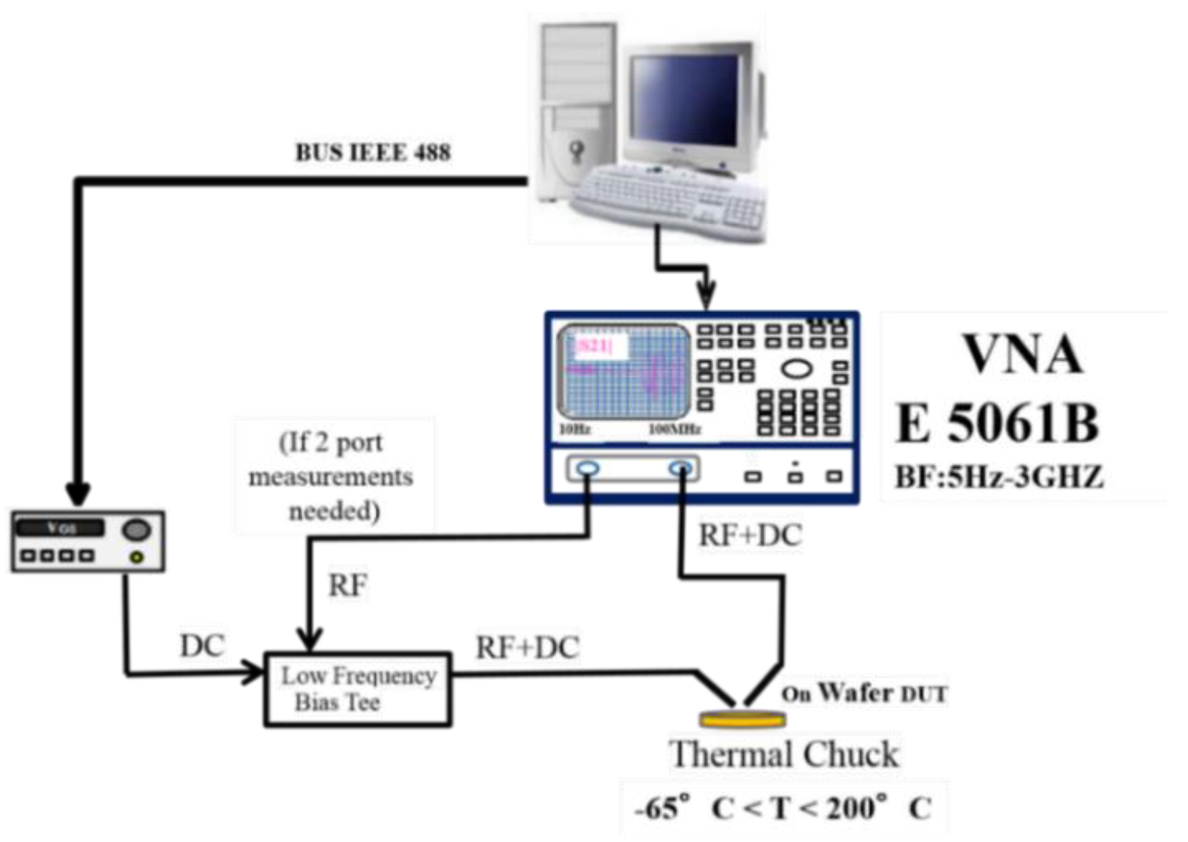
The schematic of the LF Y-parameter measurement setup is shown in Figure 2. The Agilent E5061B vector network analyzer (VNA) can measure the S-parameter of the HEMT devices over the frequencies ranging from 5 Hz to 3 GHz, and it is integrated with the internal bias system. As shown in Figure 2, the power supply voltage was fed through the DC port of the LF bias tee to gate terminal voltage for VGS, and another RF port of bias tee was connected to VNA. The drain of the HEMT device was connected to the internal bias system of the VNA for VDS and also acquiring S-parameters. Prior to the Y-parameter characterization, a traditional short open load through (SOLT) procedure was carried out for the VNA calibration. The Y21 and Y22 parameters were extracted from the S-parameter measurements at a particular bias condition (VDS = 10 V, IDS = 50 or 150 mA/mm; VDS = 20 V, IDS = 50 mA/mm) over the frequencies ranging from 10 Hz to 1 MHz.
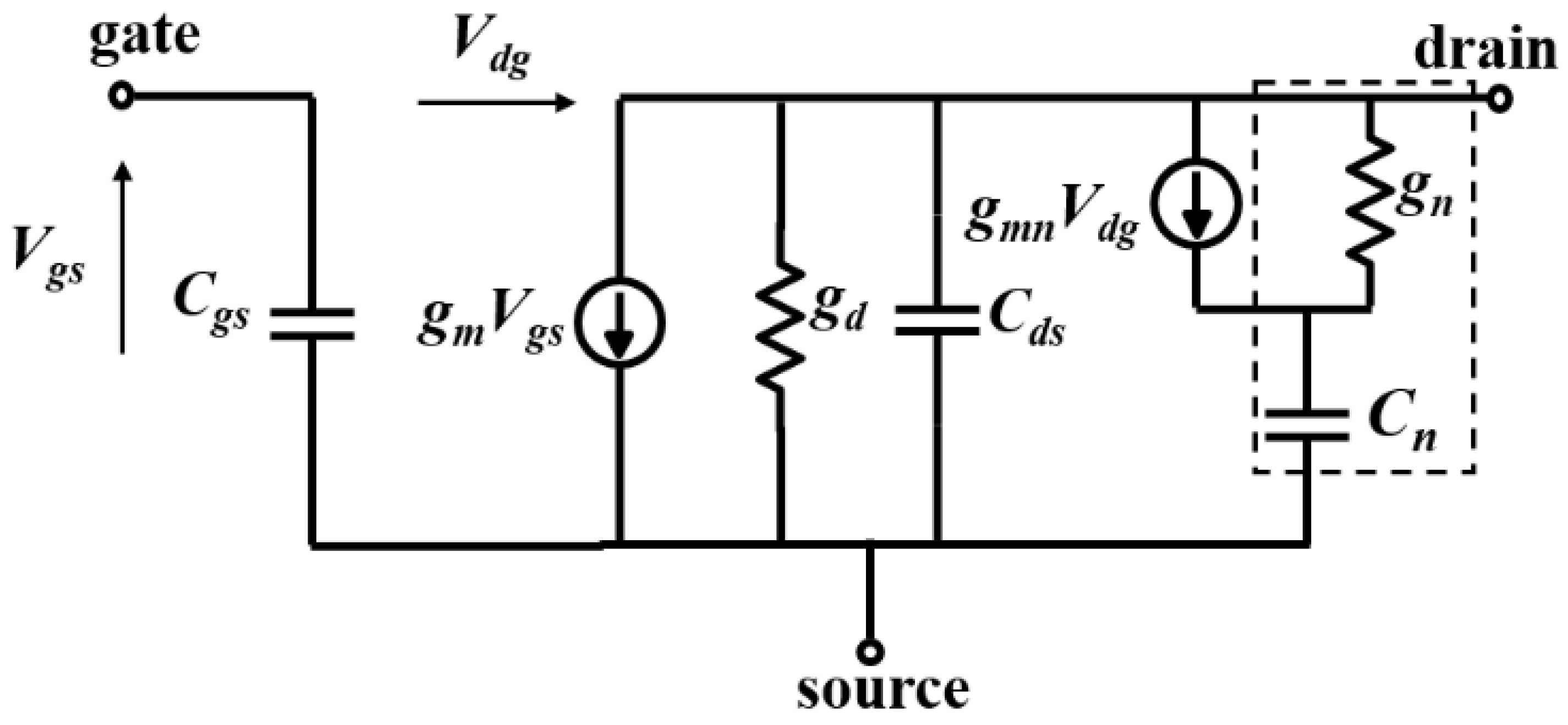
The trapping influences on the transconductance ( g m ) and output conductance ( g d ) frequency dispersion properties are accounted by including an additional parasitic RC network at the output of the HEMT equivalent small signal circuit model [19,22,24]. Figure 3 represents the small signal equivalent circuit model of the HEMT incorporating single trap signatures ( g n , C n ) . At low signal frequencies, the Y21 and Y22 parameters can be expressed as follows [22,24]:
Y 21 ( ω ) = ( g m g m n   ( ω   τ n ) 2 1 + ( ω   τ n ) 2 ) j g m n   ( ω   τ n ) 1 + ( ω   τ n ) 2
Y 22 ( ω ) = ( g d + ( g m n + g n )   ( ω   τ n ) 2 1 + ( ω τ n ) 2 ) + j ( g m n + g n )   ( ω   τ n ) 1 + ( ω   τ n ) 2
τ n = C n g n
The carrier emission time constant ( τ n ) associated with the trap is extracted from the frequency ( f I , p e a k ) that corresponds to the peak maximum of the imaginary part of the LF Y21 and Y22 spectral characteristics [22]
f I , p e a k = f Im   { Y 21 } = f Im     { Y 22 } = 1 2 π   τ n
The number of peaks in the Im {Y21} or Im {Y22} spectra indicate the number of electrically active traps existing in the HEMT device, unless the time constants of the trap overlap with each other. The Y21 or Y22 parameters were measured at different temperatures (25 °C to 100 °C) to determine the trap parameters from the Arrhenius plot.

3. Simulation Details

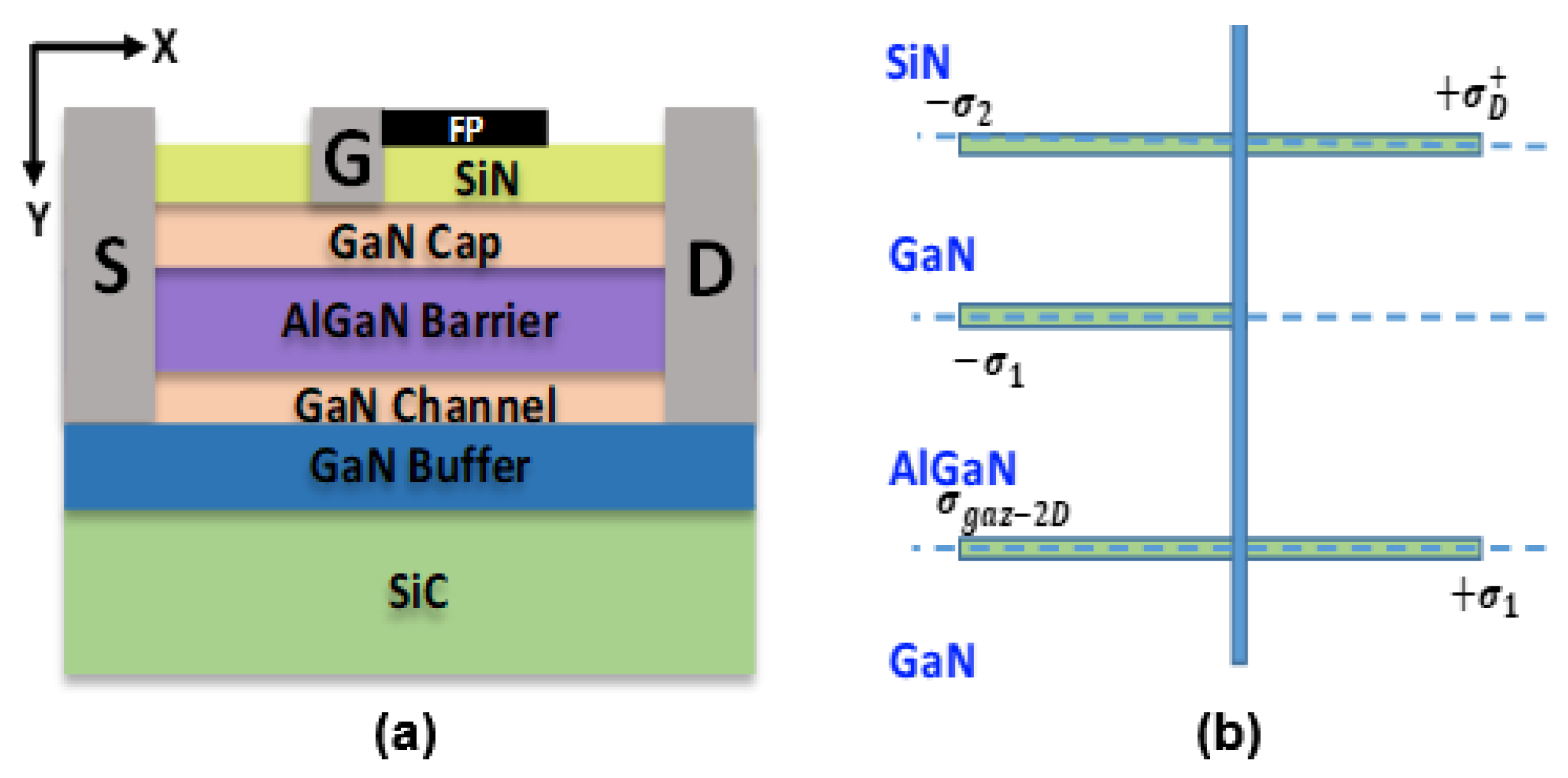
The Sentaurus TCAD tool from Synopsys Inc. (Mountain View, CA, USA) [31] is utilized for the numerical device simulations. Figure 4 shows the typical 2D device structure of the AlGaN/GaN HEMT (150 nm gate length) considered for the physical simulation. The simulated device emulates the structure of the HEMT used in our experimental studies.
The metal work function (ΦG) of the gate Schottky contact is 4.7 eV, whereas the Ohmic contact is employed for the drain and source. As illustrated in Figure 4b, the polarization charge is defined at each material interface according to the well-known research work of Ambacher et al. [32]. The polarization charge σ1 essentially depends on the Al mole fraction in the barrier layer. The values of σ1 (at either side of the barrier layer) and σ2 (at GaN/nitride interface) [25,33] are 1.4 × 1013 cm−2 and −2 × 1012 cm−2, respectively. The drift–diffusion charge transport model, Fermi–Dirac statistics, lack of bandgap narrowing in the intrinsic carrier concentration, and thermionic emission at heterointerface are considered in the physics-based TCAD model [31]. The carrier mobility due to the phonon scattering (lattice temperature dependent) is activated, along with the Canali field-dependent mobility model to incorporate the carrier saturation velocity [31]. The carrier generation–recombination models such as SRH recombination statistics, Auger recombination, and radiative recombination model in the direct bandgap materials (GaN and AlGaN) are selected [31]. Note that the studied HEMT device was fabricated on the SiC substrate, and because of its high-thermal conductivity [2,6,7,16,30], the device’s self-heating effects are less pronounced at lower bias voltages. From the experiments, the self-heating effects in the IDS-VDS and IDS-VGS properties were found to be minimal up to the drain voltage of VDS ≤ 10 V. In this work, the static I-V and Y-parameter simulations are carried out for VDS ≤ 10 V so that the thermal effects are not considered in the simulations.
The buffer trap and surface donor parameters identified from the DCT and Y-parameter measurements are taken in the TCAD physical model to incorporate the trapping phenomena. Accordingly, the surface states (σD+) are introduced at the SiN/GaN cap interface as donor-like states at EC –0.2 eV [25,30] with a density of 2 × 1013 cm−2. The electron and hole capture cross-sections of the surface donors are 3 × 10⁻¹⁸ cm2 and 10−20 cm2, respectively. The acceptor traps are placed in the buffer region at EC –0.45 eV below the conduction band. A uniform trap concentration of NTA = 1017 cm−3 is considered for the Fe-related trap at EC –0.45 eV existing in the buffer region. The electron and hole capture cross-section values of the acceptor traps are 5 × 10⁻¹⁶ cm2 and 10−20 cm2, respectively. The net recombination rate due to the trap-assisted carrier transition is computed by using the SRH recombination ( R n e t S R H ) in the TCAD simulator [31].
R n e t S R H = n   p n i e 2 τ p   ( n + n 1 ) + τ n   ( p + p 1 )
n 1 = n i e   exp     ( E t r a p / k T )
p 1 = n i e   exp   ( E t r a p / k T )
where E t r a p is between the trap energy position and intrinsic energy level, n is the electron concentration in the conduction band, n i e denotes the intrinsic carrier density, p represents the hole concentration in the valence band, k represents the Boltzmann’s constant, T is the temperature, and τ n and τ p are the electron and hole lifetimes, which are modeled as doping, electric field, and temperature-dependent factors in the SRH recombination.
As an effective approach, the DC properties of the HEMT are simulated and validated with the measured data to calibrate the material and physical model parameters [6,7,25,30]. In a mixed mode circuit configuration, the HEMT is represented as a two-port network for admittance (Y)–parameter simulation. At the specified bias point, the Sentaurus device calculates the complex Y-matrix by performing small signal AC analysis. In fact, the Y-matrix computation is a measure of small current change ( δ i ) in the circuit in response to a small voltage perturbation ( δ v ) , as given by [31]
δ i = Y   ·   δ v = ( A + j   ω   C )   ·   δ v
In the complex Y-matrix, the real part A denotes the conductance matrix, the imaginary part C signifies the capacitance matrix, and ω represents the frequency of small signal variation. Then, the Y21 and Y22 parameters are acquired from the RF extraction library of Sentaurus Visual at each frequency point.

4. Results and Discussion

4.1. Measured DCT Spectroscopy

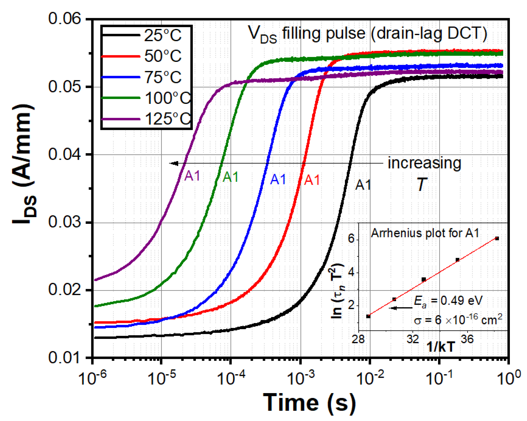
The drain current transient (DCT) spectroscopy is a powerful tool to examine the temporal evolution of the carrier trapping and de-trapping phenomena in the GaN HEMT [8,9,10,11,12,13,14,15,16,17,18]. Figure 5 depicts the DCT recovery spectra of the AlGaN/GaN HEMT acquired with the drain-lag filling pulse at increasing temperature levels. Here, the drain-lag filling pulse indicates that VDS is switched from 10 to 20 V for 100 ms during the initial trap-filling phase, and then, it is changed again to 10 V, while VGS is maintained at a fixed bias to obtain the IDS = ≈50 mA/mm; hence, it can be called drain-lag DCT spectroscopy [2,7,34]. The increasing IDS step (A1) in the DCT spectra may indicate the electron de-trapping process from an electrically active trap located below the conduction band edge (EC–ETA) [10,16]. The mid-time of the IDS step relates the emission time constant associated with the trap level. The further details of the DCT technique can be given in Refs. [8,9,10,11,12,13,14,15,16]. From Figure 5, it is noticed that the carrier emission time constant decreases with increasing temperature, specifying that the emission rate of A1 follows the Arrhenius relation [9,14]. The emission time constant ( τ n ) and activation energy ( E a ) of the trap are related with the following Arrhenius expression [16,22,25]
ln ( τ n   T 2 ) = E a k T   ln ( σ n   v t h     N C g   T 2 )
where σ n denotes the trap capture cross-section, T indicates the temperature, v t h is the carrier thermal velocity, N C is the density of states in the conduction band, and g is the degeneracy factor. The time constant of A1 is extracted at each temperature, and the Arrhenius plot is displayed in the inset of Figure 5. The trap energy (0.49 eV) and the capture cross-section (6 × 10⁻¹⁶ cm2) of A1 are identified from the Arrhenius plot based on Equation (9).
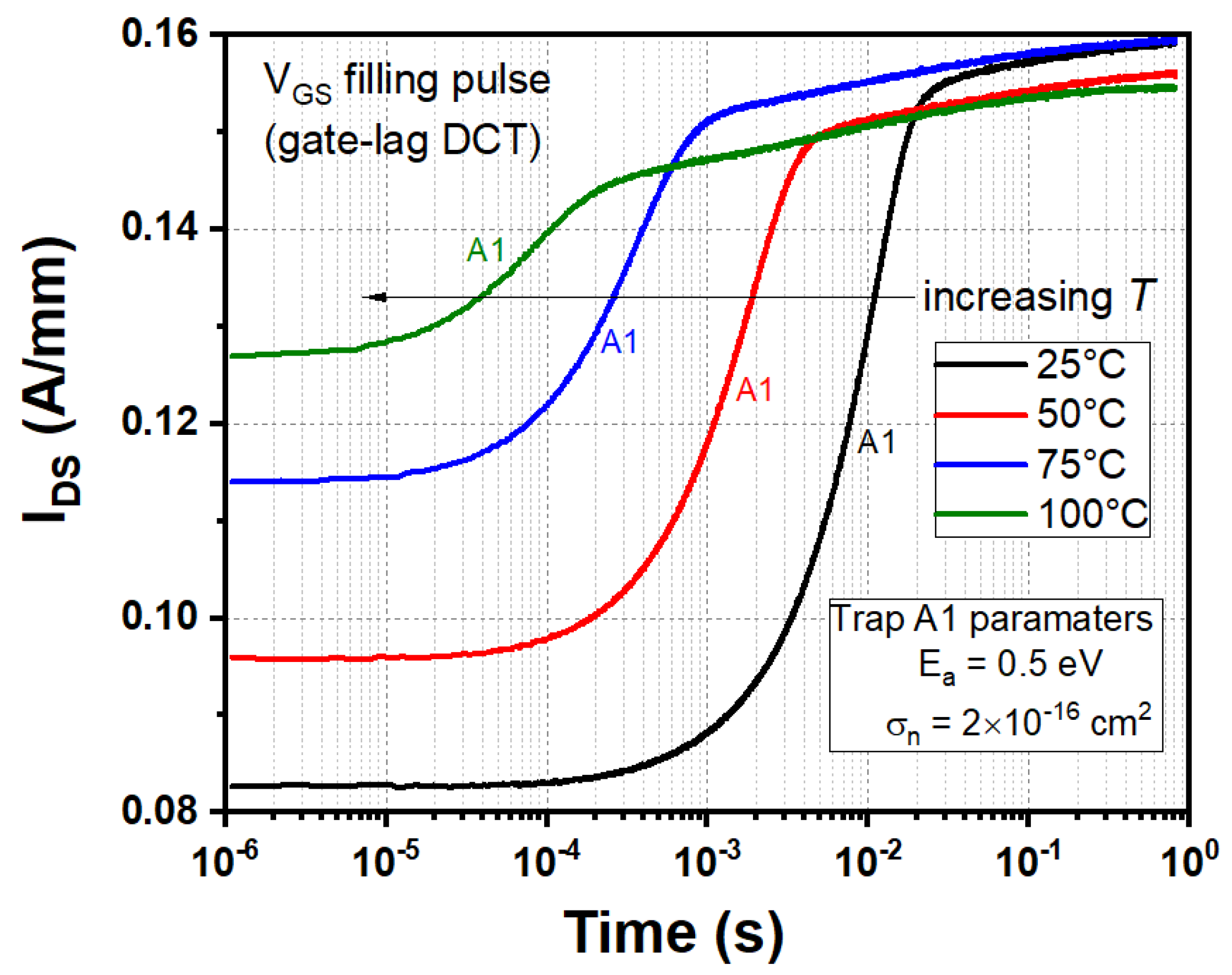
Figure 6 displays the DCT spectra of the HEMT obtained with the gate-lag filling pulse; here, the VGS pulse is changed from −2.3 to −6 V (ON-state to OFF-state) during the initial trap-filling phase (100 ms), and then, it is restored again to −2.3 V, whereas VDS is fixed, i.e., gate-lag DCT spectroscopy [2,7]. The Arrhenius investigation of the gate-lag DCT (Figure 6) reveals the identical trap A1 parameters such as ≈0.5 eV and ≈2 × 10⁻¹⁶ cm2, as detected by the drain-lag DCT spectroscopy. Similar activation energy and capture cross-section (≈0.45 eV, ≈5 × 10⁻¹⁶ cm2) are identified for the trap A1 from the Y22 measurements (discussed in Section 4.3). This specifies that the DCT and Y22 results are complement to each other for trap characterization.

4.2. Calibration of TCAD Physical Model

The 2D device simulations offer an efficient way of providing a deep understanding of device physics and exploring varying constraints in a given scenario. Nevertheless, the TCAD model calibration is absolutely necessary for performing physically meaningful simulations, and this process is not rather straightforward. The surface donor theory [35,36] indicates that the donor states are primarily responsible for the 2DEG formation in the GaN-based HEMT devices. Thus, the selection of surface donor parameters is a crucial step in the TCAD simulations. Ťapajna et al. [37] identified remarkably higher interface state densities (Dit in range of 5–8 × 10¹² eV−1 cm−2) at the insulator (Al2O3)/GaN cap interface with the trap energies ranging from EC –0.5 to –1 eV in the metal–oxide-semiconductor HEMT (MOS-HEMT) structures by using C-V characteristics. The authors found from the simulation studies that the high interface density is located near the barrier conduction band (Dit > 1013 eV−1 cm−2), which hinders the accumulation of electrons in the AlGaN barrier. Matys et al. [38] used two complementary photo-electric techniques (photo-assisted C-V and light intensity-dependent photo-capacitance) to identify the energetic distribution of the interface state density (Dit(E)) at the oxide/III–V heterointerface. They detected a continuous U-shaped Dit(E) distribution increasing toward the conduction and valence bands from the middle of the bandgap, and the interface states placed near to the valence band edge show a donor-like behavior. Moreover, it was observed that Dit(E) rises with the increasing Al content in the SiO2/AlxGa1-xN/GaN structure. So, the above reports [37,38] suggest that the interface states have a continuous energy distribution at the insulator/GaN interface. However, a discrete surface donor state is considered in the widely accepted surface donor model theory [35,36]. According to that, in this work, a distinct energetic position accounts for the donor traps existing at the GaN cap/SiN interface. Furthermore, it is observed from the TCAD simulation analysis that the ionized surface donor density (NTD+) is almost equal to the 2DEG density (ns) in the GaN channel layer (i.e., NTD+ns in cm−2) under thermal equilibrium conditions, confirming that a single donor state is sufficient to emulate the 2DEG generation mechanism in the AlGaN/GaN HEMT. The effect of surface donor energy and density on the 2DEG of the AlgaN/GaN HEMT under thermal equilibrium (zero-bias) condition is presented below.

4.2.1. Influence of ETD and NTD on 2DEG

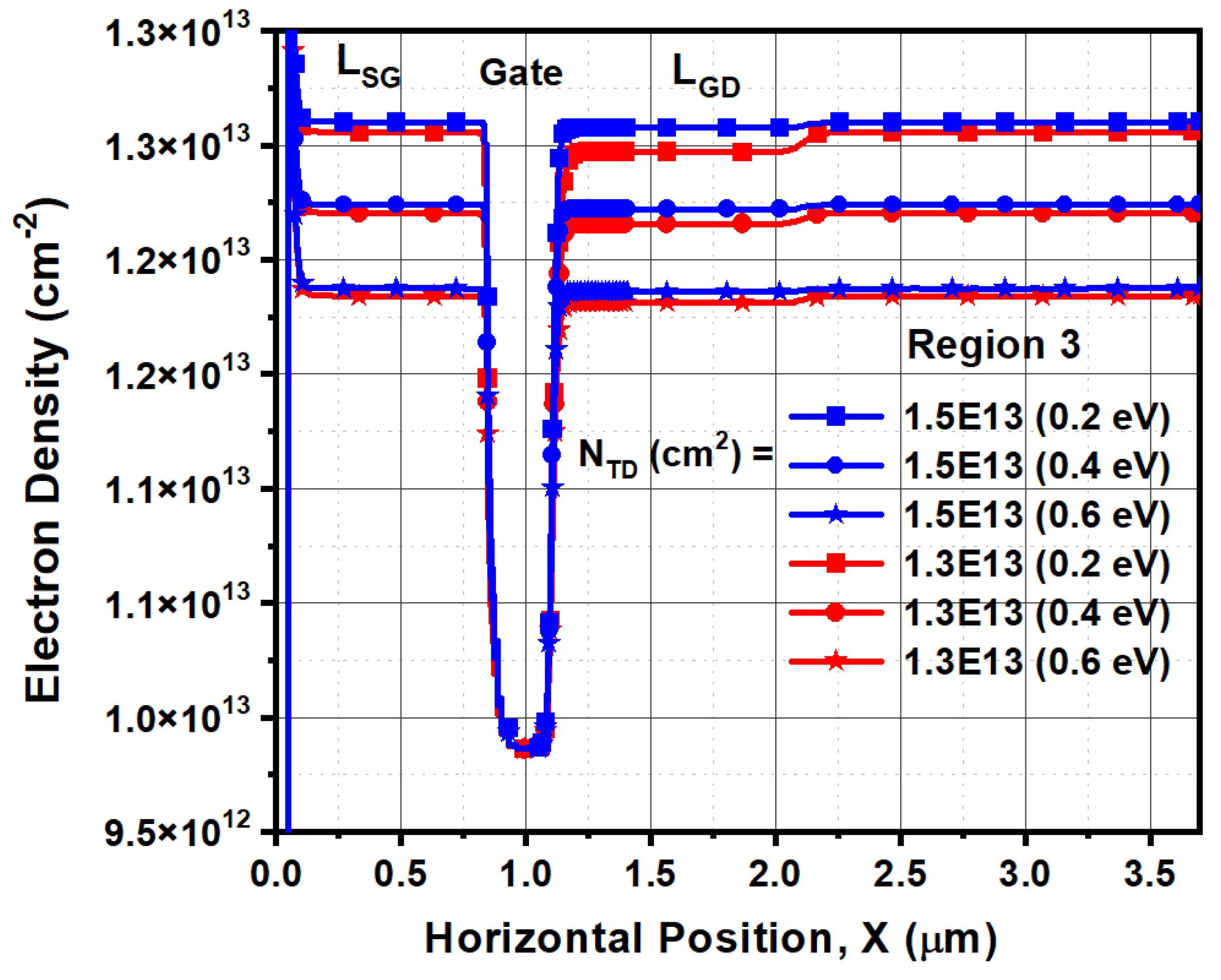
The 2DEG variations in the GaN channel layer are simulated by varying the surface donor density (NTD) at different surface donor energies (ETD) and are plotted in Figure 7. Three regions of interest are seen in Figure 7, when the surface donor density is increased from 1012 to 1.5 × 1013 cm−2 for all donor energies. In Region 1, the surface donor density (NTD) is found to be too low (≤4 × 1012 cm−2) so that NTD does not show any considerable impact on the 2DEG. In Region 2, a linear increase in the 2DEG is noticed upon increasing the donor density and is independent of the surface donor energy (ETD), as observed from Figure 7 and Figure 8. On the other hand, the 2DEG density becomes more independent of NTD in Region 3, but at the same time, ETD modulates the 2DEG in the channel, as shown in Figure 7 and Figure 9.
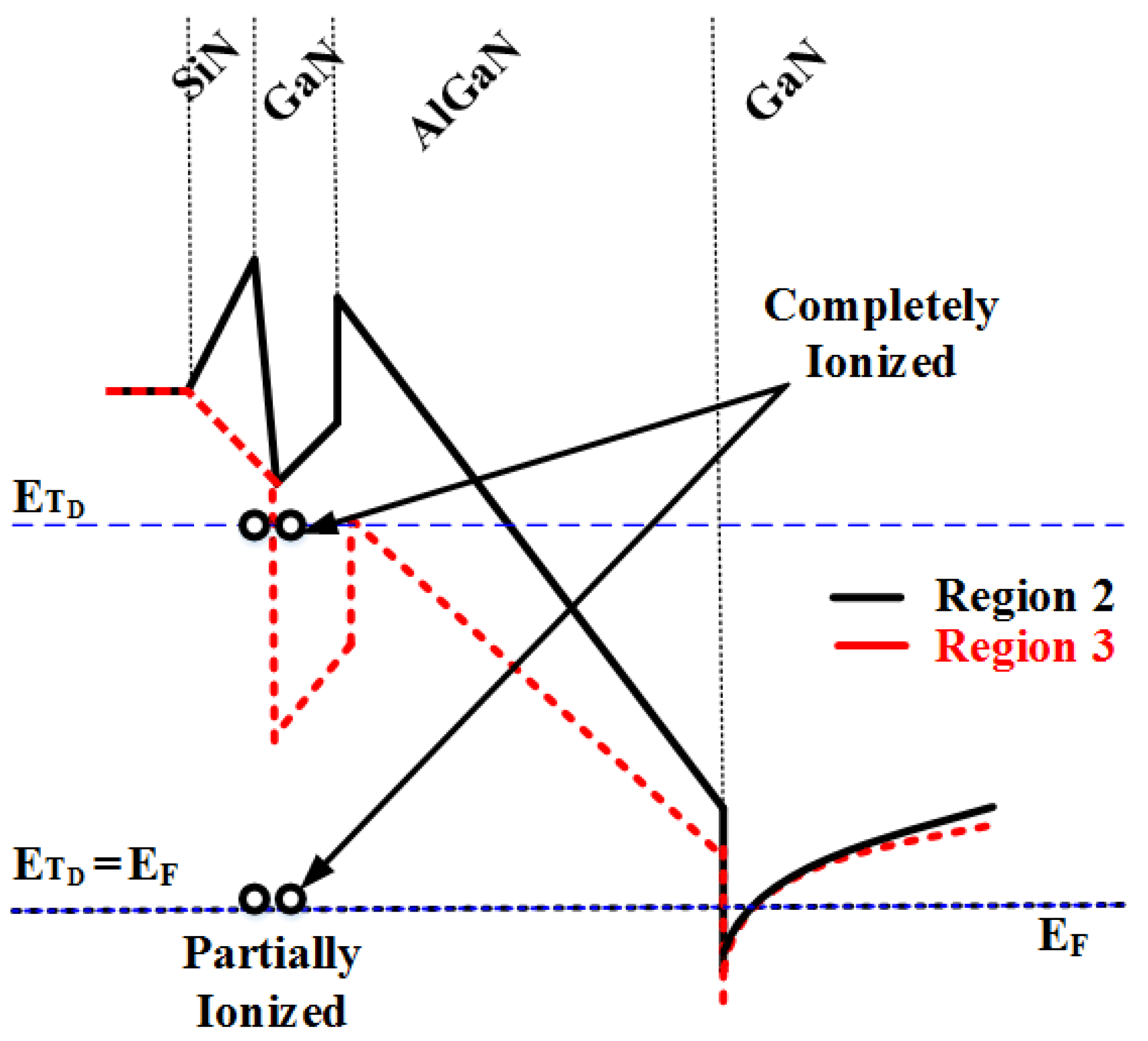
The threshold limit between Regions 1 and 2 principally depends on the interface state density (σ2) present at the Nitride/GaN interface [33]. It is visualized that the initial rise in the NTD compensates for the negative interface charge density up to the threshold value (until the end point of Region 1); thereafter, any further increase in the donor density promotes the electrons to the 2DEG at the heterointerface (in Region 2). Due to the electron donation process, the donor traps are ionized and left behind positively charged donor states (NTD+); as a result, the electric field in the AlGaN barrier is found to decrease with the increasing 2DEG density. Nonetheless, the electric field is adequately high enough to move the conduction band (EC) edge close to the surface in Region 2. Subsequently, the ETD locates effectively above the Fermi level (EF) position to ionize the donor states at the surface, as shown in Figure 10. In this case, the NTD is not adequate to pinning the EF at the ETD position [33].
In Region 3, the considered surface donor density is significantly higher, thereby resulting in a decreased electric field in the barrier layer, and ultimately, ETD aligns with the EF, as realized in Figure 10; hence, the Fermi level (EF) is pinned at the donor energy position in Region 3 (Fermi-level pinned region). As a consequence, the 2DEG channel density saturates beyond the donor density value of NTD ≥ 1.4 × 1013 cm−2, because any further increase in NTD strongly reduces the ionization probability of the surface donor traps so that the 2DEG density remains unchanged [33]. On the other hand, if the surface donor energy moves away from the conduction band edge, the donor ionization decreases due to increased AlGaN band bending; thereby, a reduction in 2DEG is observed for deeper donor energies in Region 3 (see Figure 7). Based on these simulation observations and our experimental results, the surface donor traps are positioned at EC –0.2 eV (0.2 eV below the conduction band) with the trap density of NTD = 2 × 1013 cm−2 in the TCAD physical model (discussed in Section 4.4).

4.2.2. Validation of DC Characteristics

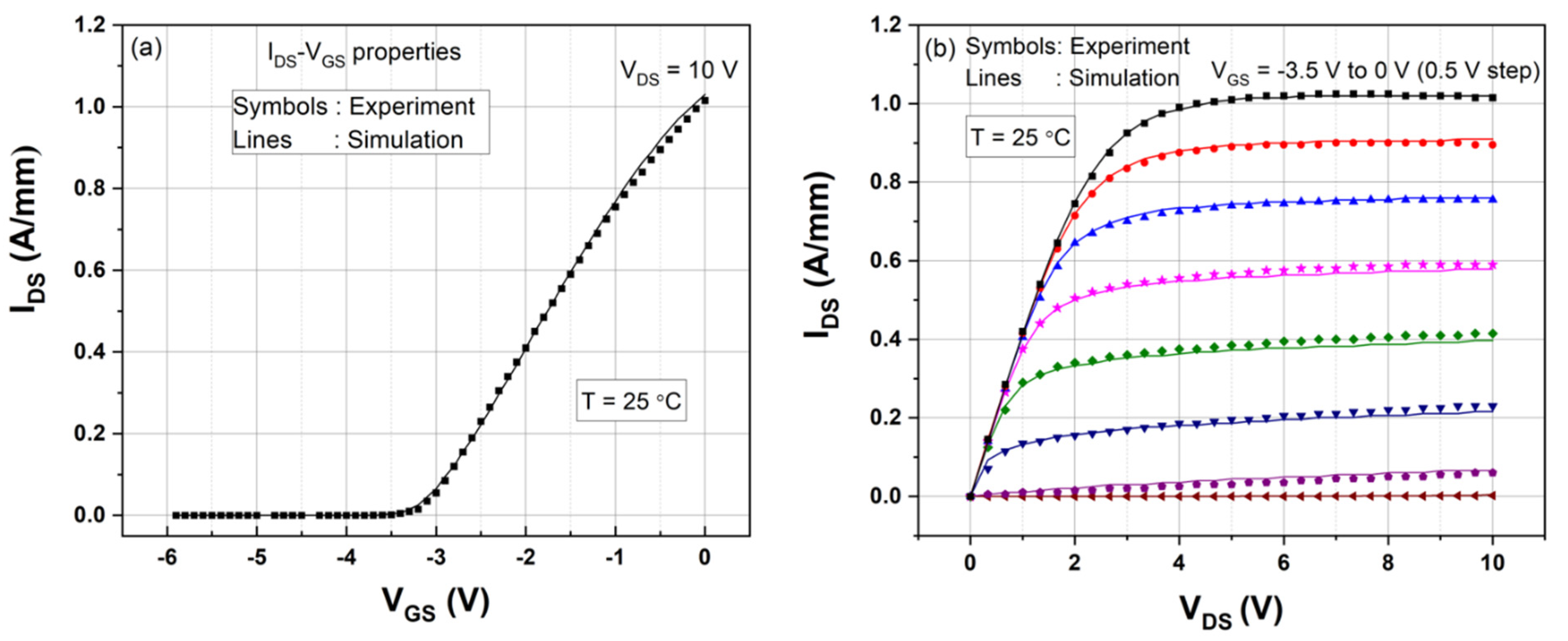
In this section, the DC characteristics of the Fe-doped AlGaN/GaN HEMT are reproduced to calibrate the material and TCAD model parameters for the Y22 and Y21 simulations. The detailed information of the static I-V simulation calibration is given elsewhere [7,25,30]. The initial calibration is performed by adjusting the acceptor-type buffer trap density (NTA) and the gate Schottky contact work function (ΦG) to match with the threshold voltage of the HEMT. Thereafter, the linear and saturation regions of the drain current characteristics are fitted with the measured data through the fine tuning of the carrier mobility and saturation velocity values in the GaN layer. Figure 11 compares the simulated IDS-VDS and IDS-VGS with the measured DC properties at 25 °C. An excellent agreement between the measurement and simulation of static I-V is observed; this demonstrates the validity of our physics-based TCAD model calibration.

4.3. Measured and Simulated Y22 Parameters

The LF Y21 and Y22 parameters can be used to inspect the trapping-induced dispersions in the transconductance (gm) and the output-conductance (gd) properties of the RF and microwave HEMTs (refer Equations (1) and (2)) [22,24]. In general, the capture rate of the trap level is substantially faster than the associated emission rate; therefore, the carrier capture emission rate may be neglected at low frequencies [22]. Due to the longer time constants, the carrier emission rate of a deep-level trap often lies in the low-frequency range (<1 MHz), so the LF Y-parameters are expected to provide the quantitative information of the deep-level electronic defects in the AlGaN/GaN HEMT.
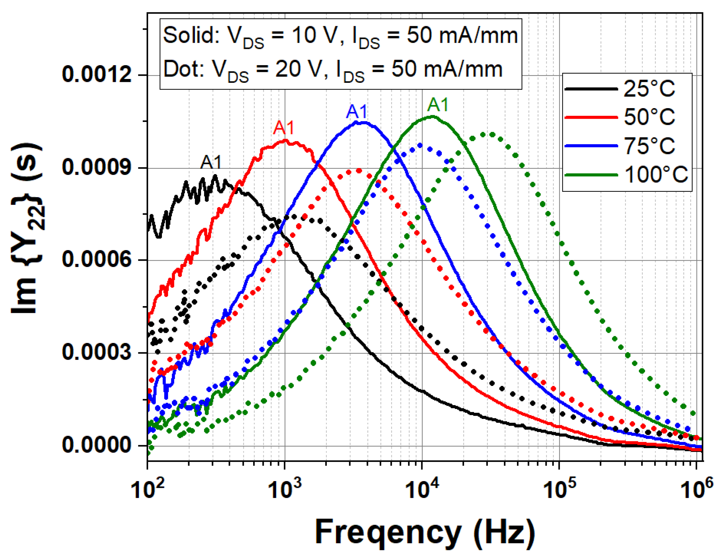
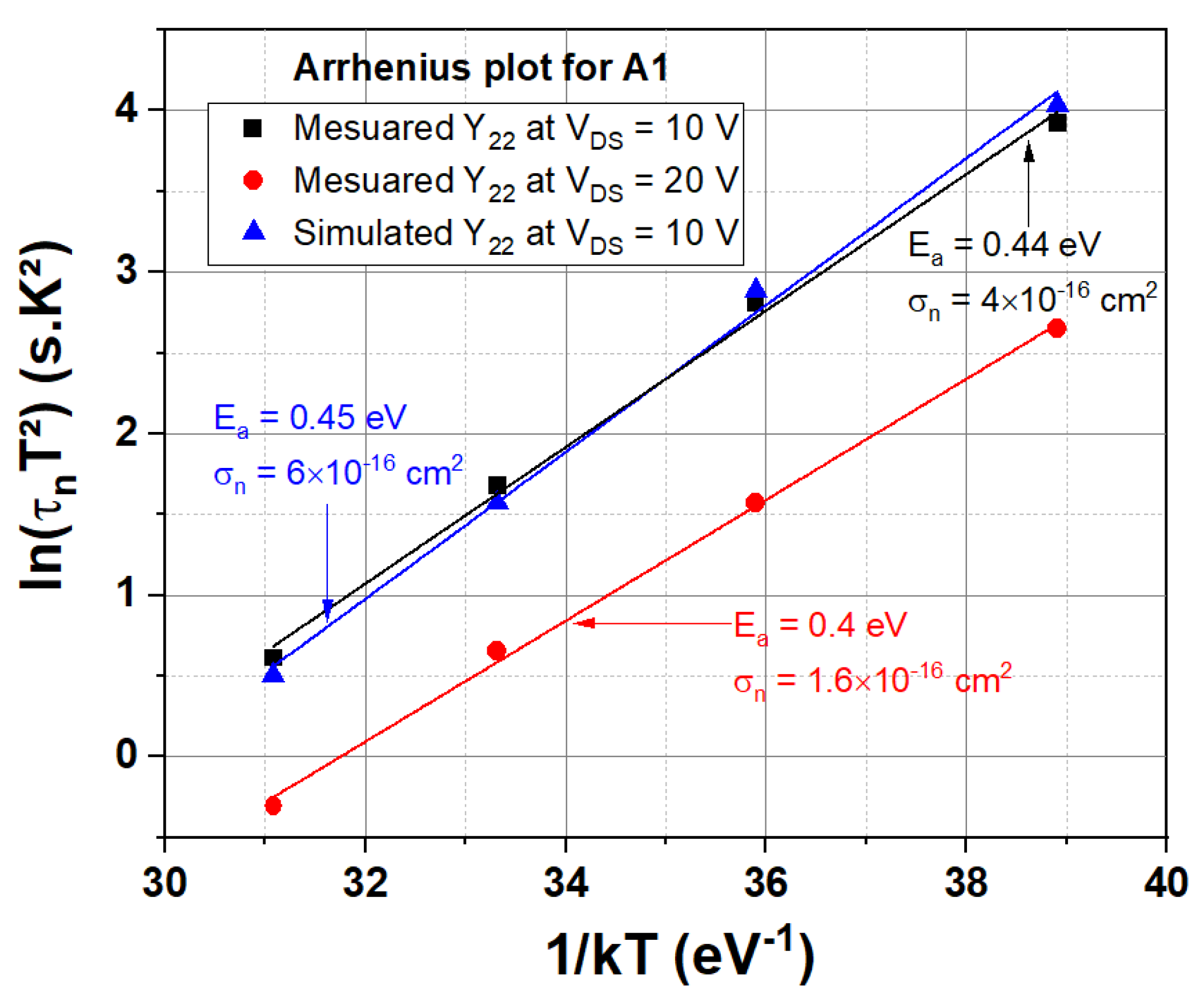
Figure 12 shows the measured LF Y22 spectra of the AlGaN/GaN HEMT acquired with two different bias points (a) VDS = 10 V, IDS = 50 mA/mm and (b) VDS = 20 V, IDS = 50 mA/mm for different chuck temperatures (from 25 to 100 °C). The imaginary part of the Y21 and Y22 parameters such as Im {Y21} and Im {Y22} were extracted from the measured admittance matrix. A distinct positive peak noticed in the Y22 spectra may reveal the existence of trap A1. The emission rate of an electrically active trap is related to the peak frequency of the Im {Y22} spectrum, according to Equation (4). It is observed from Figure 12 that the emission rate of A1 increases with the rise in temperature (for example, peak frequency fI,peak = ≈300 Hz at 25 °C, ≈1000 Hz at 50 °C), revealing that the carrier emission rate of A1 is a thermally-activated transition mechanism [9,14,22]. The Arrhenius plot for A1 is constructed from the Y22 spectra at different temperatures and is depicted in Figure 13. The Arrhenius analysis of the Y22 at VDS = 10 V yields the trap activation energy of 0.44 eV and captures the cross-section of 4 × 10⁻¹⁶ cm2 for A1, which is consistent with the DCT results. As the LF Y22 parameters represent the gd (f) dispersion phenomena [22,24], the buffer trap A1 at EC –0.45 eV is anticipated to induce the output-conductance frequency dispersions during the RF and microwave operation.
The LF Y22 spectra measured at VDS = 10 V are compared with the Y22 at VDS = 20 V for the same IDS = 50 mA/mm in Figure 12. When the VDS is augmented from 10 to 20 V, the peak position of A1 shifts toward higher frequencies because of the field-enhanced carrier emission caused by the Poole-Frenkel (PF) effect [22,39], which is explained as follows: The augmented electric field in the device lowers the potential barrier for trap-assisted thermal emission; now, the trapped carriers need relatively less thermal activation energy to release from the defect state. This potential barrier lowering ( Δ ϕ P F ) is correlated with the applied electric field ( F ) by using the following expression [39]:
Δ ϕ P F = ( q 3 π   ε ) 1 / 2 F = β F
where ε is the dielectric constant of material, and q denotes the elementary charge. In presence of the electric field, ionization energy ( E i ) associated with the trap is reduced by a value of β F as per the equation [39]
E i ( F ) = E i ( 0 ) β F
where E i ( F ) is the field-dependent ionization energy, and E i ( 0 ) = E T is the ionization energy of the defect state without the presence of the electric field, i.e., the zero-field binding energy of the carrier. Equations (10) and (11) suggest that trap activation energy computation may be undervalued at higher electric fields. The Arrhenius plot constructed from the Y22 at VDS = 20 V is shown in Figure 13. A quite lower trap activation energy of ≈0.4 eV is obtained for A1 at the VDS = 20 V condition because of the field-assisted electron emission. Some correction factor may be introduced in the Arrhenius analysis to calculate the exact activation energy at higher VDS operations. For further information, please refer to the work of Oishi et al. [27]; the authors developed an analytical model to mitigate the PF effects on the thermal activation energy computation from the Y22 parameters. Therefore, it is recommended to conduct the DCT and Y-parameter characterizations at lower drain bias voltages to eliminate both the self-heating and PF effects.
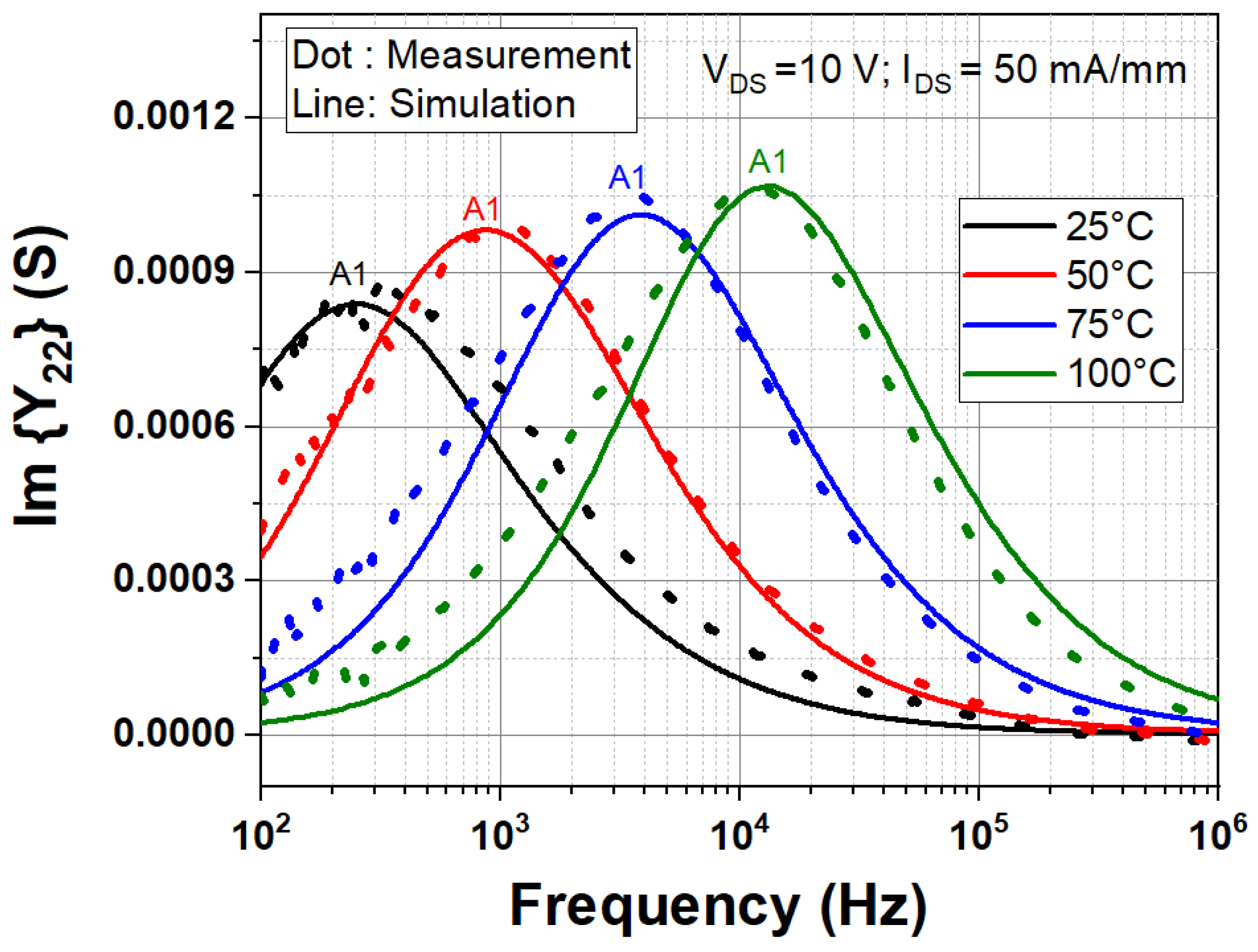
The LF Y22 simulations are carried out at the bias point VDS = 10 V, IDS = 50 mA/mm to determine the spatial location of the trap A1 in the Fe-doped AlGaN/GaN HEMT. As shown in Figure 14, the simulated LF Y22 parameters at VDS = 10 V are in good agreement with the measured spectra for the temperatures ranging from 25 to 100 °C. Hence, the Y22 simulations are validated by including the acceptor-type trap A1 at EC –0.45 eV in the GaN buffer layer. The Arrhenius investigation of the simulated Y22 also provides the same trap energy of 0.45 eV, as noted from Figure 13. The validated Y22 simulation results reveal the existence of the electron trap at EC –0.45 eV in the buffer and confirm that A1 is an acceptor-like state, supporting the reported works in the literature [7,25]. It is also found that the including barrier traps in the HEMT do not induce frequency dispersions in the Y22 characteristics. Therefore, it is shown that the DCT spectroscopy and Y22 parameters are the effective methodologies to characterize the traps in the buffer region of the AlGaN/GaN HEMTs. The deep-level traps in the Fe-doped buffer have been reported in the range of EC –0.4 to –0.7 eV [12,13,14,15,16,24,25,26,29,30]. Based on literature data [12], trap A1 at EC –0.45 eV is attributed to the intrinsic point defects in the GaN buffer, but their concentration depends on the Fe-doping density profile in the buffer. Note that the surface-trapping effects (virtual gate formation during OFF-state stress) may be less pronounced in the studied AlGaN/GaN HEMTs due to the nitride passivation [40]. If the emission time constant of A1 lies within the range of the RF signal period, the buffer trap A1 at EC –0.45 eV is foreseen to prompt the current collapse effects in the RF system.

4.4. Measured and Simulated Y21 Parameters

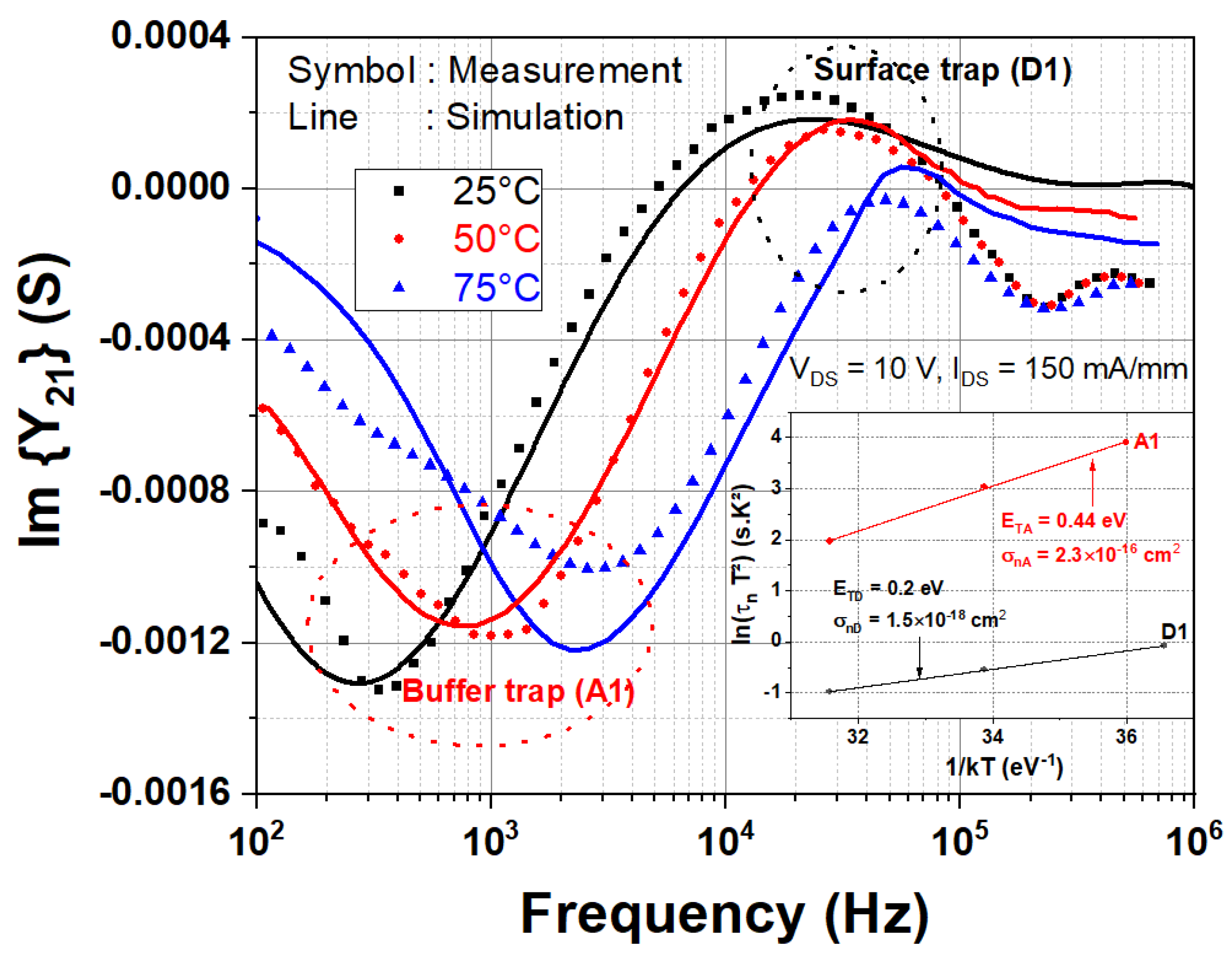
Figure 15 shows the measured and simulated LF Y21 parameters acquired at the bias point of VDS = 10 V and IDS = 150 mA/mm for different temperatures (25 to 75 °C). Negative and positive peaks are noticed in the Y21 spectra of the AlGaN/GaN HEMT, as similar to the work of Benvegnu et al. [24]. The determined trap energy and capture cross-section for the negative peak from the Arrhenius plot (see the inset of Figure 15) correspond to the buffer trap A1 signatures. It is worth remembering that the buffer trap A1 produces positive peaks in the Y22 dispersion spectra. On the contrary, negative peaks in Y21 are related to the buffer trap A1. The simulated Y21 spectra confirm that the acceptor-like buffer traps (A1) generate the negative peaks in the LF Y21 parameter spectra with similar temperature dependency, as observed from Figure 15.
The positive peak D1 position also moves toward higher frequencies with the increasing temperature, specifying that thermal evolution of the emission rate for D1 obeys the Arrhenius’s law [9,14,22]. The trap energy (≈0.2 eV) and captured cross-section (1.5 × 10⁻¹⁸ cm2) of D1 are calculated from the Arrhenius plot shown in the inset of Figure 15. Note that trap D1 is not detected from the DCT and Y22 parameters. Benvegnu et al. [24] obtained a similar trap activation energy of 0.25 eV for the positive peaks in the Y21 spectra of the AlGaN/GaN GH50 HEMTs; however, the energy and physical locations of the trap at 0.25 eV were not reported by them. In our simulation, trap D1 is positioned at an energy level of EC –0.2 eV at the SiN/GaN cap interface (i.e., surface donor states). It is noticed from Figure 15 that the simulated Y21 parameters closely track the measured spectra for various temperatures from 25 to 75 °C. Thus, the positive peaks in the Y21 correspond to the surface trapping phenomena at EC –0.2 eV, supporting the hypothesis of Yamaguchi et al. [21]. The simulated and measured results of the Y21 parameters, with a good match, illustrate the existence of both acceptor-like buffer traps at EC –0.45 eV and surface donor states at EC –0.2 eV at the nitride/GaN interface of the studied AlGaN/GaN HEMT. As Y21 parameters emulate the dispersion nature of gm (f), both the buffer and the surface traps (A1 and D1) are projected to induce the transconductance frequency dispersions during the microwave operation. Therefore, it is demonstrated that the Y21 parameters are able to discriminate traps in the surface and buffer regions, whereas Y22 and DCT properties are mostly sensitive to the buffer traps.
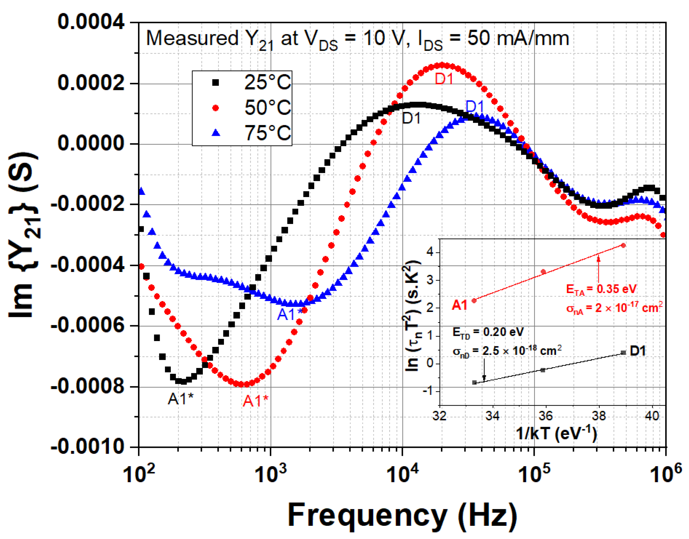
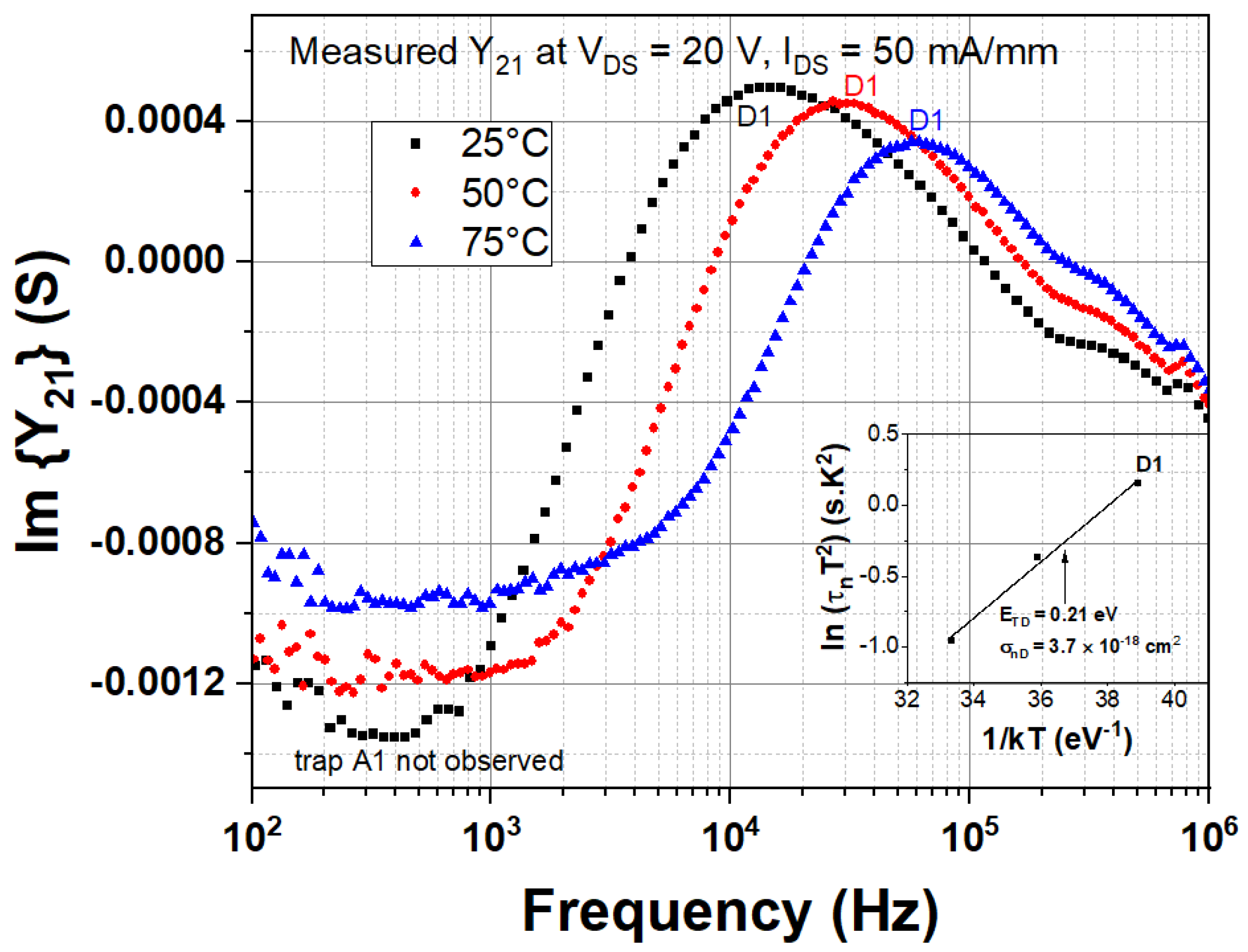
A good calibration practice is needed at each temperature to perform reliable Y21 measurements due to the high input impedance. Note that the Y21 parameter spectra strongly rely on the measurement bias points. Figure 16 displays the measured LF Y21 spectra acquired at VDS = 10 V, IDS = 50 mA/mm for various temperatures (25 to 75 °C). The positive peak D1 reveals the surface donor trap energy at ETD = EC –0.2 eV with the electron capture cross-section of σnD = 2.5 × 10⁻¹⁸ cm2. Arrhenius investigation of the negative peak A1* yields a trap activation energy of ≈0.35 eV, which is quite near to the energetic position of the trap A1 (0.4–0.5 eV). Accordingly, it may be considered that the electronic defect state A1* is located in the buffer layer. On the other hand, the surface trap D1 at EC –0.21 eV is only detected from the Y21 measurements at the bias point of VDS = 20 V, IDS = 50 mA/mm, as observed from Figure 17. The buffer trap A1 is not evident in the Y21 spectra obtained at VDS = 20 V, IDS = 50 mA/mm. These observations suggest that the surface traps are always identified with the same activation energy from the Y21 properties, while a specific bias condition may be required to detect the buffer traps from Y21. The further research investigations are underway to understand the peculiar occurrence of the buffer trap in the LF Y21 characteristics.
In the literature [8,11,40], it is reported that the surface traps may show a weak dependency on temperature, as their capture/emission kinetics is essentially governed by the hopping conduction mechanism and results in a lower thermal activation energy. In this work, both the measured and simulated Y21 properties (Figure 15, Figure 16 and Figure 17) show that the carrier emission rate for the surface trap D1 is a thermally activated process, postulating that the trapping/de-trapping dynamics is carried out through the conventional SRH recombination statistics; this observation is important to model the surface-trapping phenomena in the AlGaN/GaN HEMTs.

5. Conclusions

The charge trapping influences in the Fe-doped AlGaN/GaN HEMT device are investigated using DCT and LF Y-parameter techniques. A single trap at EC –0.45 eV is identified from the DCT and Y22 experiments. On the other hand, LF Y21 spectra reveal two trap levels at EC –0.45 eV (A1) and EC –0.2 eV (D1) in the HEMT structure. The TCAD simulation studies are performed to detect the spatial location of the trap levels in the device. The influence of surface donor energy and density on the 2DEG is analyzed under equilibrium conditions. The simulated LF Y21 parameters, with a good match, illustrate the presence of both acceptor-like buffer traps at EC –0.45 eV and surface donor states at EC –0.2 eV at the nitride/GaN interface. Hence, it is demonstrated that the Y21 parameters are able to discriminate traps in both the buffer and surface regions, while the Y22 and DCT properties are mostly sensitive to the buffer traps. Furthermore, the temperature dependent Y21 frequency dispersions indicate that the carrier trapping/de-trapping dynamics of the surface donor D1 follows the typical Arrhenius relation.

Author Contributions

Project administration, J.-C.N.; Software, P.V.R., N.K.S. and M.B.; Validation, P.V.R. and J.-C.N.; Visualization, F.G.; Writing—original draft, P.V.R., N.K.S., R.S. and J.-C.N.; Writing—review & editing, P.V.R. and J.-C.N. All authors have read and agreed to the published version of the manuscript.

Funding

This research received no external funding.

Data Availability Statement

The data presented in this study are available upon reasonable request from the corresponding author. The data are not publicly available due to the intellectual property protection rights.

Conflicts of Interest

The authors declare no conflict of interest.

References

  1. Mishra, U.K.; Shen, L.; Kazior, T.E.; Wu, Y.F. GaN-based RF power devices and amplifiers. Proc. IEEE 2008, 96, 287–305. [Google Scholar] [CrossRef]
  2. Meneghesso, G.; Verzellesi, G.; Pierobon, R.; Rampazzo, F.; Chini, A.; Mishra, U.K.; Canali, C.; Zanoni, E. Surface-related drain current dispersion effects in AlGaN-GaN HEMTs. IEEE Trans. Electron Devices 2004, 51, 1554–1561. [Google Scholar] [CrossRef]
  3. Tirado, J.M.; Sanchez-Rojas, J.L.; Izpura, J.I. Trapping effects in the transient response of AlGaN/GaN HEMT devices. IEEE Trans. Electron Devices 2007, 54, 410–417. [Google Scholar] [CrossRef]
  4. Faqir, M.; Verzellesi, G.; Chini, A.; Fantini, F.; Danesin, F.; Meneghesso, G.; Zanoni, E.; Dua, C. Mechanisms of RF current collapse in AlGaN-GaN high electron mobility transistors. IEEE Trans. Device Mater. Reliab. 2008, 8, 240–247. [Google Scholar] [CrossRef]
  5. Uren, M.J.; Moreke, J.; Kuball, M. Buffer design to minimize current collapse in GaN/AlGaN HFETs. IEEE Trans. Electron Devices 2012, 59, 3327–3333. [Google Scholar] [CrossRef] [Green Version]
  6. Zhou, X.; Feng, Z.; Wang, L.; Wang, Y.; Lv, Y.; Dun, S.; Cai, S. Impact of bulk traps in GaN buffer on the gate-lag transient characteristics of AlGaN/GaN HEMTs. Solid-State Electron. 2014, 100, 15–19. [Google Scholar] [CrossRef]
  7. Raja, P.V.; Nallatamby, J.C.; DasGupta, N.; DasGupta, A. Trapping effects on AlGaN/GaN HEMT characteristics. Solid-State Electron. 2021, 176, 107929. [Google Scholar] [CrossRef]
  8. Joh, J.; Alamo, J.A.D. A current-transient methodology for trap analysis for GaN high electron mobility transistors. IEEE Trans. Electron Devices 2010, 58, 132–140. [Google Scholar] [CrossRef] [Green Version]
  9. Bisi, D.; Meneghini, M.; De Santi, C.; Chini, A.; Dammann, M.; Brueckner, P.; Mikulla, M.; Meneghesso, G.; Zanoni, E. Deep-level characterization in GaN HEMTs-Part I: Advantages and limitations of drain current transient measurements. IEEE Trans. Electron Devices 2013, 60, 3166–3175. [Google Scholar] [CrossRef]
  10. Chini, A.; Soci, F.; Meneghini, M.; Meneghesso, G.; Zanoni, E. Deep levels characterization in GaN HEMTs-Part II: Experimental and numerical evaluation of self-heating effects on the extraction of traps activation energy. IEEE Trans. Electron Devices 2013, 60, 3176–3182. [Google Scholar] [CrossRef]
  11. Meneghesso, G.; Meneghini, M.; Bisi, D.; Rossetto, I.; Cester, A.; Mishra, U.K.; Zanoni, E. Trapping phenomena in AlGaN/GaN HEMTs: A study based on pulsed and transient measurements. Semicond. Sci. Technol. 2013, 28, 074021. [Google Scholar] [CrossRef]
  12. Meneghini, M.; Rossetto, I.; Bisi, D.; Stocco, A.; Chini, A.; Pantellini, A.; Lanzieri, C.; Nanni, A.; Meneghesso, G.; Zanoni, E. Buffer traps in Fe-doped AlGaN/GaN HEMTs: Investigation of the physical properties based on pulsed and transient measurements. IEEE Trans. Electron Devices 2014, 61, 4070–4077. [Google Scholar] [CrossRef]
  13. Axelsson, O.; Gustafsson, S.; Hjelmgren, H.; Rorsman, N.; Blanck, H.; Splettstoesser, J.; Thorpe, J.; Roedle, T.; Thorsell, M. Application relevant evaluation of trapping effects in AlGaN/GaN HEMTs with Fe-doped buffer. IEEE Trans. Electron Devices 2015, 63, 326–332. [Google Scholar] [CrossRef]
  14. Bergsten, J.; Thorsell, M.; Adolph, D.; Chen, J.T.; Kordina, O.; Sveinbjörnsson, E.Ö.; Rorsman, N. Electron trapping in extended defects in microwave AlGaN/GaN HEMTs with carbon-doped buffers. IEEE Trans. Electron Devices 2018, 65, 2446–2453. [Google Scholar] [CrossRef]
  15. Bouslama, M.; Gillet, V.; Chang, C.; Nallatamby, J.C.; Sommet, R.; Prigent, M.; Quéré, R.; Lambert, B. Dynamic performance and characterization of traps using different measurements techniques for the new AlGaN/GaN HEMT of 0.15 µm ultrashort gate length. IEEE Trans. Microw. Theory. Tech. 2019, 67, 2475–2482. [Google Scholar] [CrossRef]
  16. Raja, P.V.; Bouslama, M.; Sarkar, S.; Pandurang, K.R.; Nallatamby, J.C.; DasGupta, N.; Dasgupta, A. Deep-level traps in AlGaN/GaN-and AlInN/GaN-based HEMTs with different buffer doping technologies. IEEE Trans. Electron Devices 2020, 67, 2304–2310. [Google Scholar] [CrossRef]
  17. Angelotti, A.M.; Gibiino, G.P.; Florian, C.; Santarelli, A. Trapping dynamics in GaN HEMTs for millimeter-wave applications: Measurement-based characterization and technology comparison. Electronics 2021, 10, 137. [Google Scholar] [CrossRef]
  18. Santi, C.D.; Buffolo, M.; Meneghesso, G.; Zanoni, E.; Meneghini, M. Dynamic performance characterization techniques in gallium nitride-based electronic devices. Crystals 2021, 11, 1037. [Google Scholar] [CrossRef]
  19. Umana-Membreno, G.A.; Dell, J.M.; Nener, B.D.; Faraone, L.; Parish, G.; Wu, Y.F.; Mishra, U.K. Low-temperature shallow-trap related output-admittance frequency dispersion in AlGaN/GaN MODFETs. In Proceedings of the IEEE Conference on Optoelectronic and Microelectronic Materials and Devices. Proceedings (Cat. No. 98EX140), Perth, Australia, 14–16 December 1998; pp. 252–255. [Google Scholar] [CrossRef]
  20. Nsele, S.D.; Escotte, L.; Tartarin, J.G.; Piotrowicz, S.; Delage, S.L. Broadband frequency dispersion small-signal modeling of the output conductance and transconductance in AlInN/GaN HEMTs. IEEE Trans. Electron Devices 2013, 60, 1372–1378. [Google Scholar] [CrossRef] [Green Version]
  21. Yamaguchi, Y.; Oishi, T.; Otsuka, H.; Nanjo, T.; Koyama, H.; Kamo, Y.; Yamanaka, K. Modeling of frequency dispersion at low frequency for GaN HEMT. In Proceedings of the IEEE Asia-Pacific Microwave Conference, Sendai, Japan, 4–7 November 2014; pp. 798–800. [Google Scholar]
  22. Potier, C.; Jacquet, J.C.; Dua, C.; Martin, A.; Campovecchio, M.; Oualli, M.; Jardel, O.; Piotrowicz, S.; Laurent, S.; Aubry, R.; et al. Highlighting trapping phenomena in microwave GaN HEMTs by low-frequency S-parameters. Int. J. Microw. Wirel. Technol. 2015, 7, 287–296. [Google Scholar] [CrossRef]
  23. Gustafsson, S.; Chen, J.T.; Bergsten, J.; Forsberg, U.; Thorsell, M.; Janzén, E.; Rorsman, N. Dispersive effects in microwave AlGaN/AlN/GaN HEMTs with carbon-doped buffer. IEEE Trans. Electron Devices 2015, 62, 2162–2169. [Google Scholar] [CrossRef]
  24. Benvegnù, A.; Bisi, D.; Laurent, S.; Meneghini, M.; Meneghesso, G.; Barataud, D.; Zanoni, E.; Quere, R. Drain current transient and low-frequency dispersion characterizations in AlGaN/GaN HEMTs. Int. J. Microw. Wirel. Technol. 2016, 8, 663–672. [Google Scholar] [CrossRef]
  25. Subramani, N.K.; Couvidat, J.; Hajjar, A.A.; Nallatamby, J.C.; Sommet, R.; Quéré, R. Identification of GaN buffer traps in microwave power AlGaN/GaN HEMTs through low frequency S-parameters measurements and TCAD-based physical device simulations. IEEE J. Electron Devices Soc. 2017, 5, 175–181. [Google Scholar] [CrossRef]
  26. Subramani, N.K.; Couvidat, J.; Hajjar, A.A.; Nallatamby, J.C.; Floriot, D.; Prigent, M.; Quéré, R. Low-frequency noise characterization in GaN HEMTs: Investigation of deep levels and their physical properties. IEEE Electron Device Lett. 2017, 38, 1109–1112. [Google Scholar] [CrossRef]
  27. Oishi, T.; Otsuka, T.; Tabuchi, M.; Yamaguchi, Y.; Shinjo, S.; Yamanaka, K. Bias dependence model of peak frequency of GaN trap in GaN HEMTs using low-frequency Y₂₂ parameters. IEEE Trans. Electron Devices 2021, 68, 5565–5571. [Google Scholar] [CrossRef]
  28. Green, B.M.; Chu, K.K.; Chumbes, E.M.; Smart, J.A.; Shealy, J.R.; Eastman, L.F. The effect of surface passivation on the microwave characteristics of undoped AlGaN/GaN HEMTs. IEEE Electron Device Lett. 2000, 21, 268–270. [Google Scholar] [CrossRef]
  29. Subramani, N.K.; Couvidat, J.; Hajjar, A.A.; Nallatamby, J.C.; Quéré, R. Low-frequency drain noise characterization and TCAD physical simulations of GaN HEMTs: Identification and analysis of physical location of traps. IEEE Electron Device Lett. 2017, 39, 107–110. [Google Scholar] [CrossRef] [Green Version]
  30. Subramani, N.K.; Sahoo, A.K.; Nallatamby, J.C.; Sommet, R.; Rolland, N.; Medjdoub, F.; Quéré, R. Characterization of parasitic resistances of AlN/GaN/AlGaN HEMTs through TCAD-based device simulations and on-wafer measurements. IEEE Trans. Microw. Theory. Tech. 2016, 64, 1351–1358. [Google Scholar] [CrossRef]
  31. Sentaurus TCAD User Guide; Version N-2017.09; Synopsys Inc.: San Jose, CA, USA, 2017.
  32. Ambacher, O.; Foutz, B.; Smart, J.; Shealy, J.R.; Weimann, N.G.; Chu, K.; Murphy, M.; Sierakowski, A.J.; Schaff, W.J.; Eastman, L.F. Two dimensional electron gases induced by spontaneous and piezoelectric polarization in undoped and doped AlGaN/GaN heterostructures. J. Appl. Phys. 2000, 87, 334–344. [Google Scholar] [CrossRef]
  33. Longobardi, G.; Udrea, F.; Sque, S.; Hurkx, G.A.; Croon, J.; Napoli, E.; Šonský, J. Impact of donor traps on the 2DEG and electrical behavior of AlGaN/GaN MISFETs. IEEE Electron Device Lett. 2013, 35, 27–29. [Google Scholar] [CrossRef]
  34. Mukherjee, J.; Malik, A.; Vinayak, S.; Rawal, D.S.; Dhaka, R.S. Deep trap characterization and the kink effect in AlGaN/GaN HEMTs. IETE Tech. Rev. 2020, 1–8. [Google Scholar] [CrossRef]
  35. Smorchkova, I.P.; Elsass, C.R.; Ibbetson, J.P.; Vetury, R.; Heying, B.; Fini, P.; Haus, E.; DenBaars, S.P.; Speck, J.S.; Mishra, U.K. Polarization-induced charge and electron mobility in AlGaN/GaN heterostructures grown by plasma-assisted molecular-beam epitaxy. J. Appl. Phys. 1999, 86, 4520–4526. [Google Scholar] [CrossRef]
  36. Ibbetson, J.P.; Fini, P.T.; Ness, K.D.; DenBaars, S.P.; Speck, J.S.; Mishra, U.K. Polarization effects, surface states, and the source of electrons in AlGaN/GaN heterostructure field effect transistors. Appl. Phys. Lett. 2000, 77, 250–252. [Google Scholar] [CrossRef]
  37. Ťapajna, M.; Jurkovič, M.; Válik, L.; Haščík, Š.; Gregušová, D.; Brunner, F.; Cho, E.M.; Hashizume, T.; Kuzmík, J. Impact of GaN cap on charges in Al2O3/(GaN/)AlGaN/GaN metal-oxide-semiconductor heterostructures analyzed by means of capacitance measurements and simulations. J. Appl. Phys. 2014, 116, 104501. [Google Scholar] [CrossRef]
  38. Matys, M.; Adamowicz, B.; Domanowska, A.; Michalewicz, A.; Stoklas, R.; Akazawa, M.; Yatabe, Z.; Hashizume, T. On the origin of interface states at oxide/III-nitride heterojunction interfaces. J. Appl. Phys. 2016, 120, 225305. [Google Scholar] [CrossRef] [Green Version]
  39. Mitrofanov, O.; Manfra, M. Poole-Frenkel electron emission from the traps in AlGaN/GaN transistors. J. Appl. Phys. 2004, 95, 6414–6419. [Google Scholar] [CrossRef] [Green Version]
  40. Rossetto, I.; Bisi, D.; Santi, C.; Stocco, A.; Meneghesso, G.; Zanoni, E.; Meneghini, M. Performance-limiting traps in GaN based HEMTs: From native defects to common impurities. In Power GaN Devices Materials, Applications and Reliability, 1st ed.; Springer: Basel, Switzerland, 2017; pp. 197–236. [Google Scholar]
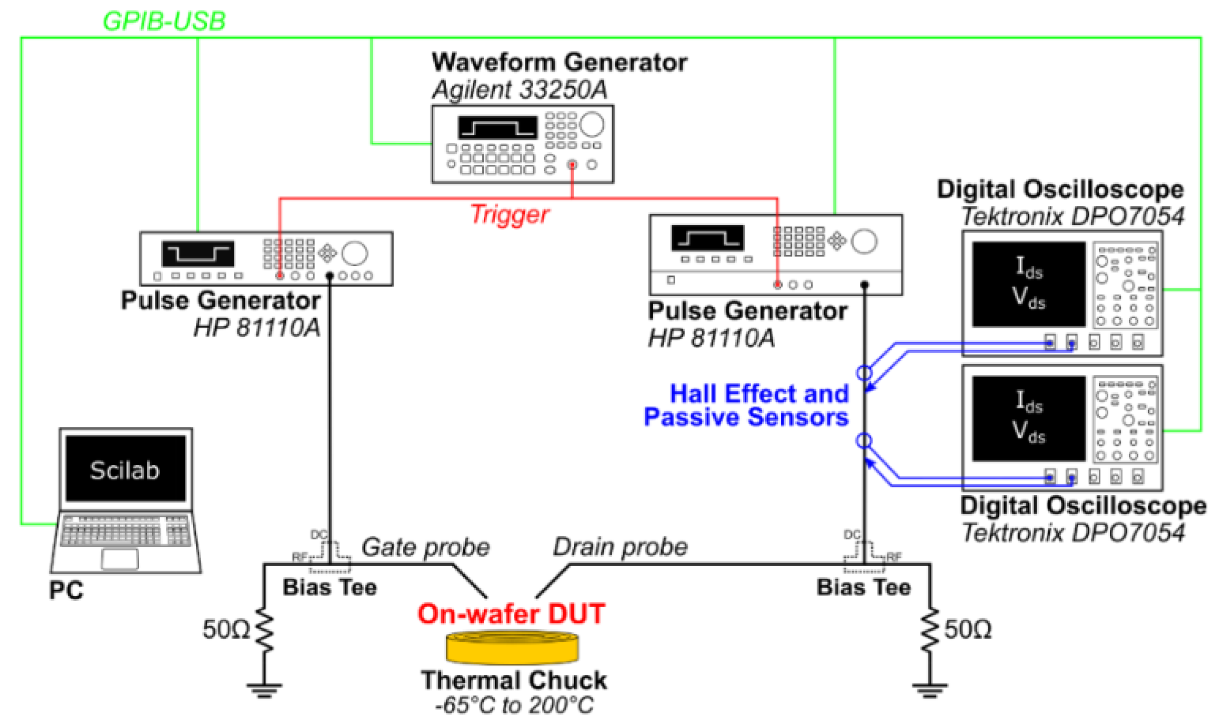
Figure 1. Drain current transient (DCT) spectroscopy measurement setup for AlGaN/GaN HEMT.
Electronics 10 03096 g001
Figure 2. The experimental setup of the LF Y-parameter characterization by using an Agilent E5061B vector network analyzer (VNA).
Electronics 10 03096 g002
Figure 3. HEMT equivalent small signal circuit model accounting single trap signatures (gn, Cn).
Electronics 10 03096 g003
Figure 4. (a) Typical 2D structure of the AlGaN/GaN HEMT (0.15 um gate length) used in the simulations. (b) Distribution of polarization charges at each material interface.
Electronics 10 03096 g004
Figure 5. The drain current transient (DCT) spectroscopy of AlGaN/GaN HEMT acquired with the drain-lag filling pulse (VDS pulsed from 10 to 20 V for 100 ms during the trap-filling phase) at increasing temperature levels. The Arrhenius plot for A1 is displayed in the inset.
Electronics 10 03096 g005
Figure 6. DCT spectra obtained with the gate-lag filling pulse (VG pulsed from −2 to −5 V during the trap-filling phase) also reveal the trap A1 at 0.5 eV.
Electronics 10 03096 g006
Figure 7. The 2DEG density simulated by varying the surface donor density at different donor energies (ETD). Three regions (R1, R2, and R3) are clearly visible in the figure.
Electronics 10 03096 g007
Figure 8. The 2DEG density versus lateral device distance (X) simulated for different ETD and NTD values under thermal equilibrium (zero-bias) conditions for Region 2.
Electronics 10 03096 g008
Figure 9. The 2DEG density versus lateral device distance (X) attained for various ETD and NTD values under the thermal equilibrium condition for Region 3.
Electronics 10 03096 g009
Figure 10. The conduction band variations illustrate the effect of surface donor traps on the 2DEG density in Regions 2 and 3. If ETD aligns with EF, the surface donor traps are partially ionized, whereas when the ETD locates effectively above the Fermi level, all the donor states are completely ionized.
Electronics 10 03096 g010
Figure 11. Simulated (a) transfer (IDS–VGS) and (b) output (IDS–VDS) properties of the Fe-doped AlGaN/GaN HEMT are validated with the measured DC results.
Electronics 10 03096 g011
Figure 12. Measured LF Y22 spectra acquired with two different bias points (Solid) VDS = 10 V, IDS = 50 mA/mm, and (Dot) VDS = 20 V, IDS = 50 mA/mm for different chuck temperatures (25 to 100 °C).
Electronics 10 03096 g012
Figure 13. Arrhenius plots for the trap A1 obtained from the measured Y22 parameters at VDS = 10 V and 20 V are shown along with the simulation case at VDS = 10 V.
Electronics 10 03096 g013
Figure 14. The simulated LF Y22 characteristics at VDS = 10 V are validated with the measured spectra for different temperatures of 25 to 100 °C.
Electronics 10 03096 g014
Figure 15. The simulated and measured LF Y21 parameters at VDS = 10 V, IDS = 150 mA/mm for different temperatures (25 to 75 °C) indicate two traps: A1 at EC –0.44 eV and D1 at EC –0.2 eV. The simulation analysis reveals that trap D1 corresponds to the surface donor states.
Electronics 10 03096 g015
Figure 16. The measured LF Y21 spectra acquired at VDS = 10 V, IDS = 50 mA/mm for different temperatures (25 to 75 °C) reveal a buffer trap A1* at EC –0.35 eV and surface donor at EC –0.2 eV.
Electronics 10 03096 g016
Figure 17. The measured LF Y21 parameters obtained at VDS = 20 V, IDS = 50 mA/mm for various temperatures (25 to 75 °C) show only the surface donor at EC –0.21 eV. The buffer trap A1 is not detected for this bias condition.
Electronics 10 03096 g017
Publisher’s Note: MDPI stays neutral with regard to jurisdictional claims in published maps and institutional affiliations.