1. Introduction
Smart manufacturing is a technology-driven approach that utilizes advanced manufacturing technologies and tools driven or enhanced by integrated information technology.
The goals are manifold and diverse, such as making innovation and the manufacturing process more manageable, providing more flexible production, responding in real time to meet changing demands and conditions, making the manufacturing system collaborative, environmentally effective, etc.
In the strict sense, manufacturing is the fabrication of goods to be sold, and industry has a broader meaning that includes the production of goods, the related ecosystems, and related services, too. The terms smart manufacturing, smart industry, and Industry 4.0 (the fourth industrial revolution) are often used interchangeably. The strong common points drive the transition towards data-focused operations, network-wide integrated information and communication technologies, and increased automation.
A data network is mandatory to interconnect all of the systems for any smart factory, becoming the most important and the most critical asset at the same time. The network must deliver time-sensitive data accurately between the control equipment, such as programmable logic controllers (PLCs) and the controlled devices.
Time-sensitive networking (TSN) was developed by the Institute of Electrical and Electronics Engineers (IEEE) [
1] to enable deterministic communication on standard Ethernet. Prior to the TSN standards, deterministic communication was based on proprietary technologies or non-standardized Ethernet. TSN technology is centrally managed and provides guarantees of delivery and minimized jitter using time scheduling for applications that require determinism.
There is an increasing need for wireless connectivity and real-time data transmission with mobile robots and automatic guided vehicles (AGVs) that move in the factory. 5G, the fifth generation of mobile networks, is foreseen as the key to enhancing and enabling these advances in manufacturing, as it offers low latency and high-speed connections. The integration of 5G technologies in the manufacturing ecosystem has great potential to accelerate the ongoing digital transformation of the manufacturing industry.
Since different uses of the terms edge and cloud computing have been adopted in industrial applications, the terminology used in this article for the computing domains is defined in the following.
Cloud computing is a very centralized paradigm where processing and data storage are realized on centralized servers located in a remote data center.
Edge computing is a distributed computing paradigm that has processing and data storage capability right at “the edge” of a given application’s network, closer to the source of data. As an advantage, collecting and processing data closer to the source reduces latency and brings better performance to high-bandwidth applications.
From the technical point of view, the main differentiating factors between cloud and edge computing are the location of the computing power and the centralized vs. distributed nature. Cloud or edge computing can be used independently or combined, whatever best fits the specific use case.
Industrial edge computing is a system of micro data centers installed at the edge of the network, close to or within the premises of the factories. In edge computing, the computing tasks are executed closer to the end users or devices in terms of geographical and network proximity. This allows for delivering levels of latency and throughput that are not possible with cloud computing. On the one hand, the tasks executed in edge computing are data processing and analytics to be close to where the data is generated and captured. On the other hand, the evolving edge computing and networking technologies (TSN, 5G) make it possible to offload industrial control applications to edge computing to provide control loops with tight delay requirements, too.
Providing an end-to-end solution for smart manufacturing is not straightforward. This paper fills this gap by identifying and analyzing interworking aspects of different fields of communication and computing, i.e., 5G, TSN, and the edge computing domains, to deliver smart manufacturing and suggests approaches and technical aspects to enable the realization of such systems by evaluating different scenarios.
The paper is structured as follows:
Section 2 provides technical details about how 5G and TSN, as well as 3GPP non-public networks can be used for industrial communication networks. This section also introduces edge and cloud computing, considering the manufacturing context.
Section 3 discusses and analyzes the characteristics of the integration options of 5G non-public network (5G NPN) deployment and edge computing scenarios. Further,
Section 4 provides architectural and conceptual analysis of how TSN and edge computing domains can be integrated in order to provide enhanced end-to-end reliability. Finally, the paper discusses and concludes the main findings and outlook regarding the tight integration of different technology domains in the manufacturing scenario.
2. Background
In this section, the different technical enablers are overviewed on how the 5G system (5GS) is harmonized and integrated with communication technologies used in the industry domain to support Industry 4.0 use cases. The section also gives a brief introduction to edge computing, presenting the edge incentives, related standardization status, and cloud management basics.
2.1. 5G Support for Industrial Networks
Nowadays, the communication between industry machines, end devices, controllers, as well as production cells/lines is based on legacy fieldbus technologies or industrial Ethernet technology (e.g., different real-time Ethernet variants), while the larger subnetworks are interconnected on the Internet Protocol (IP) level. Due to the fragmented market of industrial networking technologies, numerous different technologies can be deployed in particular factory premises.
However, over recent years, there has been intensive work to develop a converged, standardized networking technology, which can fulfill the strict requirements of the Industry 4.0 use cases. The result is the set of time-sensitive networking (TSN) standards specified by the IEEE 802.1, which extend the bridged Ethernet to provide a future-proof solution for time-sensitive applications and is expected to replace the different fieldbus technologies and the various legacy real-time Ethernet variants [
2]. The corresponding TSN standards specify the details of deterministic communication, time synchronization, high reliability, as well as enhanced resource management by enabling the support of a wide range of applications that require robust data transport with bounded, ultra-low latency, low jitter, and extremely low loss.
From Release 15, 3GPP focuses on several technology enablers aiming at how 5G can support industrial use cases, and such a way facilitates the seamless integration of 5G systems with industrial networks. On the one hand, the “Ethernet” type packet data unit (PDU) session was introduced by enabling the 5G network to handle Ethernet frames directly. Then, a set of radio- and architecture-level features are defined that enhance the ultra-reliable low latency communication (URLLC), ensuring the bounded latency data transmission on a redundant path over the 5G segment.
Furthermore, in Release 16, the support of TSN is introduced, where the 5G system is modeled as a logical TSN bridge on per a user plane function (UPF) base. By enabling the interconnection of the 5G system with the legacy TSN network segment in a seamless way and ensuring the handling of TSN streams, 3GPP introduced the TSN translator function in the user plane at the User Equipment (device TSN translator) and the UPF side (network TSN translator) that acts as a gateway functionality. In the control plane, a TSN application function (TSN AF) is defined by enabling the 5G control plane to interact with the centralized network configuration (CNC) entity of the TSN segment according to the IEEE 802.1Qcc. The TSN AF reports the capabilities of the 5GS bridge towards the CNC, and based on this information, the CNC configures the 5GS bridge as well as calculates the traffic paths and schedule of a specific TSN stream. Then, the CNC pushes the corresponding bridge configuration (e.g., scheduled traffic, per-stream filtering and policing (PSPF) according to IEEE 802.1Qci, traffic forwarding information) to the 5GS. In order to provide sufficient quality of service (QoS) for the TSN streams in the 5GS segment, the TSN traffic streams are mapped to the corresponding 5G QoS flows. Furthermore, to optimize the transmission over the 5G radio, the detailed traffic pattern of the TSN streams can optionally also be obtained from the PSPF information by the TSN AF, and it is forwarded to the 5G base stations by allowing more efficient scheduling of the TSN traffic. 5GS also supports the TSN time synchronization feature according to IEEE 802.1AS by enabling the time synchronization of end devices that connects to the TSN system via the 5GS segment.
The 5G Alliance for Connected Industries and Automation (5G-ACIA) published a white paper about the integration of 5G with time-sensitive networking for industrial communication [
3]. The paper extensively discusses and validates the different 5GS-TSN integration options in a factory environment. An integrated 5GS-TSN architecture is defined by covering the industrial backbone network and the machine/production line segments, considering the user and the control plane integration aspects. Then, an integrated 5GS-TSN network deployment is presented in different factory communication scenarios, such as ‘controller-to-controller’, ‘controller-to-device’, and ‘device-to-compute’. The main finding is that valuable benefits can be achieved for industrial use cases with the integration of the 5G and TSN communication networks in the factory environment.
2.2. 5G Non-Public Networks for Industrial Communication
In order to offer customized 5G solutions for serving the needs of particular enterprise customers (e.g., factories), 3GPP introduces the non-public networks (NPN) architecture concept that enables 5GS deployments for private use. According to the 3GPP TS23.501, an NPN could be categorized as:
Standalone NPN (SNPN), which is deployed in an isolated way from the public network and operated by an NPN operator;
Public network integrated NPN (PNI-NPN), which is deployed with the support of a public land mobile network (PLMN), e.g., by allocating one (or more) network slice instances for the NPN.
In [
4], 5G-ACIA describes four variants of NPN deployment options. The first one is the standalone NPN, while the other three belong to the PNI-NPN and differ in the degree of interaction and infrastructure sharing with the public network.
In the case of a standalone NPN, all of the 5G network functions are located in a certain enterprise (e.g., factory) premises, and the complete 5G infrastructure is totally separated from the public network. The industrial party or a third-party integrator is responsible for operating and maintaining the SNPN as the NPN operator. However, it is possible to establish a roaming agreement with a mobile network operator (MNO), so the public network can also be reached in this case.
The second deployment option is the PNI-NPN with a shared radio access network (RAN), in which case all 5G core network functions (including user and control plane) remain isolated. Thus, the traffic is handled on-premises, however, the RAN is shared with the public network. In order to fulfill the required communication service requirements, proper local radio planning and dimensioning are required for the NPN.
The third deployment option is the PNI-NPN with a shared RAN and control plane, where the 5G control plane is also shared. The segregation between the private and public networks can be ensured by using network slicing. Since the User Equipment (UE) is also PLMN subscriber, seamless mobility between the NPN and the public network is guaranteed. In order to enable the proper management of this deployment option, the interaction between the MNO’s management system and the industrial party’s management system is required.
The fourth deployment option is when the NPN is hosted by the public network, where NPN is provided by an MNO. All user and control plane network functions are deployed in the public network and can be used for both public and private network purposes. It should be considered that in this case, all of the traffic is routed via the public network, so the separation of the public network and NPN segments can be ensured by using network slicing. Since all NPN subscribers are also subscribers of the public network, roaming is enabled between the PLMN and the NPN.
In 3GPP, the 5G-TSN support and the non-public networks currently are on separate tracks; however, the evolution towards an integrated solution is expected. In [
5], the 5G integration with TSN for different NPN deployment options is discussed. SNPN enables the most flexible and tight integration of legacy industrial TSN and 5G NPN network deployment, considering the user plane design and the network management. In the dedicated user plane and shared control plane option, it is proposed to deploy the dedicated control plane function for TSN traffic handling on-premises. In the NPN hosted by the public network scenario, a dedicated slice is required for the TSN services.
2.3. Edge Computing Overview
This section aims to give a brief introduction to edge computing by summarizing the most relevant incentives for using edge computing in industrial environments, briefly overviewing the related standardization activities and the related work in the area of edge computing and industrial networking. Generic edge and cloud computing scenarios and some examples with the Kubernetes cloud management platform are also provided.
2.3.1. Edge Computing Incentives in Manufacturing
Edge computing [
6,
7] provides an ecosystem where the execution environment (e.g., compute and storage resources) is closer to the location where it is needed in contrast with a remote cloud. The proximity of the edge premises results in reduced latency between a client and the server application, so edge computing can support use cases where ultra-low latency and high-reliability characteristics are crucial. The typical usage of edge computing in smart manufacturing could be to perform tasks on the edge infrastructure that are intensive in complexity, computation, memory, and storage. For example, various analytics and monitoring tasks can be executed in the edge domain, utilizing the cloud capabilities (e.g., resource scalability, robustness, flexible application software management) and processing huge amounts of data locally. However, edge computing with (near-) real-time cloud execution capabilities, integrated with 5G NPNs and Ethernet-based industrial networks will be able to provide ultra-low end-to-end latency to support a wide range of the time-critical Industry 4.0 use cases. Moreover, such an edge computing solution enables offloading of the time-critical industrial device (closed-loop) control functions, such as mobile robot control intelligence from the device to the edge domain.
Consequently, edge computing is not limited only to improve the effectiveness of existing use cases, but it can support new or evolved use cases as well:
Edge can host such resource-consuming (industrial control) tasks, which cannot be deployed on a device (due to limited compute resource or battery power). For example, edge computing can enable more complex AI/ML supported control mechanisms for mobile robots (e.g., AGVs), which can improve the efficiency of the service;
The edge-enabled, centralized device control makes it possible to support extensive coordination between different devices (e.g., AGVs, robotic arms), resulting in improvements in productiveness;
Edge computing enables the balance between local (close to the premises where the data is generated) and central cloud-based data processing.
2.3.2. Standardization Overview
Edge computing is a quite fragmented and evolving ecosystem, and additionally, the standards and business models are in the phase of maturing. This section aims to give a quick overview of the status of the main standardization directions.
The global standardization body for mobile communication technology is 3GPP. Several working groups within 3GPP are focusing on edge computing. In the 3GPP SA2 working group, the technical specification on 5G system enhancements for edge computing [
8] and 5G system architecture [
9] specify the details on how user traffic is routed to the appropriate edge application server within 5GS, covering edge application server discovery, UPF selection and connectivity models that enable edge computing for edge-unaware devices. In the 3GPP SA6 working group, TS 23.558 [
10] defines an architecture for edge computing support of the devices with edge-aware capabilities. The proposed architecture includes an edge enabling layer, which facilitates the communication between the application clients and the servers (e.g., optimized edge application server discovery, network exposure capabilities towards the edge application server). In the 3GPP SA5 working group, a study is running on the life-cycle management aspect of the application servers in the edge cloud [
11].
The European Telecommunications Standards Institute (ETSI) multi-access edge computing (MEC) initiative has created an open and standardized information technology (IT) service environment, which allows third-party applications to be hosted at the edge of the mobile network and which is capable of exposing network and context information. It specifies a framework for service delivery, Application Programming Interfaces (API) for exposure and programmability, as well as covering the management and orchestration operations. The ETSI MEC studies federated architecture to support multi-operator, multi-vendor scenarios. The ETSI MEC also makes efforts to propose a synergized architecture leveraging the ETSI MEC and 3GPP specifications [
12].
The Global System for Mobile Communications Association (GSMA) specifies an end-to-end high-level architecture and provides an edge cloud service description mainly from the telco operator perspective. GSMA also describes stakeholder roles and different business models for telco operators in the edge ecosystem.
The 5G Alliance for Connected Industries and Automation (5G-ACIA) also investigates the role and capabilities of edge computing; its enablers and architecture are analyzed, together with how edge computing can be applied to industrial use cases.
2.3.3. Edge and Cloud Computing Scenarios and Examples with the Kubernetes Platform
Depending on the requirements of industrial applications and services and the connectivity options of the factory, different computing environments can be set up as a combination of edge and cloud computing.
Standalone Edge: Only edge computing is deployed on-premises as a fully functional cluster. Some factories are not Internet-connected yet or are located in remote areas with poor network availability. This option enables local processing capabilities, without interconnection towards a Cloud;
Integrated Edge and Cloud: Contains both edge and cloud, where edge computing extends cloud computing, and cloud computing contains the control plane for both;
Federated Edge(s) and Cloud: Contains several edges or both edge and cloud, where multiple edge or edge and cloud computing clusters cooperate, with individual but federated control planes.
The combined operation of edge and cloud computing provides intelligent collaboration and flexible migration of services between the cloud and the edge, application-level software migration, and portability between them with fault tolerance as well.
As an illustrative example, we demonstrate the realization of edge and cloud computing scenarios based on Kubernetes (K8s) [
13] clusters as the container orchestration platform. A lightweight virtualization layer is provided by containers, where the software application and all of its dependencies are packaged into container images. Kubernetes is an open-source system for automating deployment, scaling, and management of containerized applications. Kubernetes is becoming the de facto orchestration for enterprise containers and has become a cloud-native standard for deploying complex applications using lightweight and portable containers. It supports workload abstraction, such as pod, deployment, service, etc., and is capable of a rolling upgrade and rollback of applications.
Here, we give a brief summary of Kubernetes basic concepts that are referred to later in the article as well. A Kubernetes cluster is a set of nodes that can either be virtual machines or physical servers connected to the same network that work together to operate as one cloud platform.
Pods are the smallest and most basic deployable objects in Kubernetes. A pod represents a single instance of a running application in the cluster. Pods contain one or more containers, such as Docker containers. When a pod runs multiple containers, the containers are managed as a single entity, share the pod’s resources, and run on the same node. A pod can be considered as a self-contained, isolated “logical host”.
Deployments represent a set of multiple, identical pods. A deployment runs multiple replicas of an application and manages the life cycle of the constituent pods, such as automatically replacing any instances that fail or become unresponsive. In this way, deployments help ensure that one or more instances of applications are available to serve user requests. In addition, a deployment can also perform horizontal scaling, i.e., changing the number of pods within the deployment as necessary.
Services are an abstract way to expose an application running on a set of pods. A service gives a single Domain Name System (DNS) name and IP address representing the set of pods and can load-balance across them.
Figure 1 shows the realization of the edge and cloud computing scenarios with Kubernetes platforms.
A standalone edge can be realized with K3s by Rancher [
14]. It is a lightweight, certified Kubernetes-compliant distribution built for Internet of Things (IoT) and edge computing. The developers aimed to run Kubernetes in low, fixed resource environments. All of the components of K3s run on the edge; therefore, no cloud-side collaboration is involved. If the on-premises hardware resources are powerful enough, a Kubernetes cluster can also be installed and used as a standalone cluster on the edge (
Figure 1 top part).
An integrated edge and cloud solution is provided by KubeEdge [
15], which is made to build edge computing solutions to extend the central cloud. KubeEdge is built upon Kubernetes and provides core infrastructure support for networking, application deployment, and metadata synchronization between the cloud and edge (
Figure 1 middle part). KubeEdge consists of a cloud part and an edge part, both edge and cloud parts are open-sourced.
A federated edge and cloud can be built using Kubernetes cluster federation (KubeFed for short) [
16]. KubeFed allows for coordination of the configuration of multiple Kubernetes clusters from a single set of APIs in a hosting cluster. KubeFed aims to provide mechanisms for expressing which clusters should have their configuration managed and what that configuration should be (
Figure 1 lower part). The benefit is that any resources configured to take advantage of the federation will treat all member clusters as a single distributed cluster.
2.4. Related Work
The authors in [
6] present an extensive overview of edge computing by positioning edge computing and discussing the state of the art related to the edge computing paradigm, characteristics (e.g., big data analytics, resource management, security, and privacy), and requirements (e.g., resource management, real-time application support, scalability) in detail. The paper ends with a summary of open challenges for edge computing, emphasizing service discovery and mobility, robust deployment models, and collaboration between heterogeneous edge computing systems. In [
17], the authors show the multi-access edge computing framework and reference architecture, present an extensive survey about the MEC integration and deployment options into 5G networks, different MEC enablers (e.g., network function virtualization, network slicing), and overview some MEC approaches for latency, compute resources, and energy efficiency optimization in the MEC concept.
In [
18], the authors propose a generic, hierarchical, layered architecture for smart manufacturing based on edge, fog, and traditional cloud computing and discuss which manufacturing processes can be handled by a certain layer considering the industry use case requirements. The paper also presents an illustrative application example.
The authors in [
19] propose a hybrid computing framework considering the device, cloud, and edge compute capabilities, as well as design and evaluate an intelligent resource scheduling strategy to fulfill the real-time requirement in smart manufacturing.
In [
20], the authors present a reference architecture and offer various practical approaches for consideration to embark on the digital journey towards smart manufacturing, as well as analyze the pros and cons of the different approaches.
In [
21], a system architecture is described for an IoT-based manufacturing scenario, covering device, network, data, and application domain. A case study is also presented for active maintenance where the authors build a distributed data processing system in the cloud. In [
22], the use of edge computing in automation and manufacturing industrial contexts is presented, describing the problem space and introducing a reference architecture model for edge computing.
In [
23], the authors give an overview of the existing solutions of edge computing in 5G, and a taxonomy is given in which the edge computing approaches are classified, also showing that the convergence of edge computing and 5G brings new issues to be resolved. In [
24], the authors briefly summarize the different NPN deployment modes and show a case study on how a 5G NPN and edge-enabled system can be used to realize an industrial vision detection system.
In [
25], different 5G-enabled solutions for factory manufacturing are discussed, including out-factory, in-factory, and integrated 5G network deployment options. In the latter case, the authors show how TSN and 5G networks can be integrated in order to ensure URLLC communication towards the factory local edge. As an illustrative example, the remote control of a gantry crane from the edge is also presented.
In [
26], the authors propose to use TSN as the networking solution to interconnect a fog computing node to its environment in a factory (e.g., sensors, actuators) in order to serve industry-grade applications. A detailed system configuration case study and its experimental evaluation are also shown.
The authors in [
27] propose IndustEgde, an edge-cloud collaborative intelligent (ECCI) platform system, where TSN is used for the link layer transport to reduce the system level latency for the real-time industrial applications. In addition to the detailed system design, two case studies for evaluating the effectiveness of IndustEdge have also been carried out.
As presented above in
Section 2.1,
Section 2.2,
Section 2.3.3 and
Section 2.4, the integration of different technical enablers (such as 5G-TSN, NPN) that support industry use cases is a key factor, and such integration is ongoing by focusing mainly on industry communication networking. However, from the end-to-end point of view, it is important to consider not only the details of the networking domain but also the various architectural and deployment aspects and options in the edge computing domain. The goal of the rest of the paper is to investigate different integration options for the NPN deployment models and edge scenarios by emphasizing various edge deployment alternatives which were not investigated by previous works in a detailed way. Our further goal is to analyze how seamless interworking between the TSN and the edge domains can be established to provide a redundant, low latency, end-to-end solution that fits for the industry use case requirements. Consequently, we consider that TSN is not only a networking layer for the edge domain, but it is tightly integrated with it, and some TSN functions are virtualized and deployed in the edge, which is, according to our best knowledge, not studied in detail so far. Furthermore, our intention was to deeply investigate the details of how Kubernetes cloud management features can be applied to support industry use cases with low-latency requirements.
3. Integration of 5G NPN Deployment Options and Edge Computing Scenarios
Considering the end-to-end scope, it is important to investigate how the different edge computing setups can interwork with the 3GPP NPN deployment options. The investigated integration scenarios are summarized in
Table 1. In some industry use cases, the edge computing domain will be deployed locally, in the factory premises (to fulfill the use case requirements), and SNPN is applied. Hence, several combination scenarios of edge computing and SNPN deployments are investigated. Here, it is also considered if the infrastructure of the edge and NPN domains are isolated or shared. Since the footprint of the telco operators enables us to provide edge computing services for factory enterprises, different scenarios are also investigated where PNI-NPN deployment options are combined with an MNO-provided edge solution.
3.1. Standalone NPN with Private, On-Premises Edge
As shown in
Figure 2, in this scenario, all of the user plane and control plane functions required to operate the NPN are physically located on factory premises. The edge deployment that hosts the latency-critical industry applications (e.g., cloud-based mobile robot control) is also on-premises, and dedicated infrastructure is used for the edge. Due to the totally separated infrastructure for the edge and SNPN domains, this scenario ensures the highest isolation for the industry applications running at the edge.
The industrial network domain, which comprises the SNPN and wired network segments, connects the industrial end devices to the edge computing domain. The on-premises edge enables a wide range of deployment alternatives:
A single, standalone data center could be deployed in the factory premises;
Several edge (standalone) data centers could be deployed in different factory buildings, realizing a distributed edge infrastructure for improved robustness, and each data center is managed as a separate edge computing cluster;
Another operation mode is to handle the multiple clusters in a federated way;
Beside the on-premises edge data center(s), a central (public or private) cloud premises is also used for hosting industry applications/application functions with relaxed requirements (e.g., latency).
The private, on-premises edge deployment enables lots of flexibility for the edge owner (typically the industrial party in this scenario or a third-party integrator); however, the edge owner is responsible for the handling of the full cloud stack, including:
The infrastructure layer (e.g., compute and storage resources, as well as cloud networking) has to provide low latency (e.g., near-real-time) and high availability capabilities (support the redundant deployment of application instances)
Maintenance of the virtualization platform, such as container runtime environment (e.g., Docker [
28]) or virtual machine (VM)-based ecosystem;
Maintenance of the cloud orchestration system, e.g., proper installation and management of Kubernetes components (e.g., provide the redundancy of the Kubernetes control plane, Kubernetes cluster configuration, etc.)
Depending on the stakeholder roles, the above tasks could be handled by the industrial party (self-managed deployment), a third-party integrator, or even the MNO. In the two latter cases, the industrial party should only perform the application deployment and life-cycle management, while in the first case, the industrial party is responsible for the proper operation of the full cloud stack. The on-premises edge scenario enables numerous deployment options; the most specific ones are discussed in the next part of the section.
3.1.1. Standalone Edge Data Centers
This alternative is suitable for such industry scenarios, where each component of an application software runs locally at the edge. A typical example could be the edge-enabled (collaborative) control of the fleet of mobile robots, where all of the control components, which are offloaded from the industrial end device, have to be deployed on the on-premises edge due to low latency and on-premises data handling.
One deployment option is to have only a single edge data center on the factory premises. Even in this case, multiple execution environments can be deployed at the edge in order to support the various requirements of applications, e.g., OpenStack supports virtual machines, bare-metal servers, and containers from one control plane or virtual machines and Kubernetes clusters can be run in the same data center when the Kubernetes clusters are deployed on virtual machines.
Alternatively, multiple standalone data centers could be deployed, with different hardware infrastructure and connectivity, as well as platform capabilities. This enables the different data center infrastructures, as well as platforms, to meet the requirements (real-time execution environment, support of hardware acceleration, etc.) of the different industrial applications (e.g., real-time device control applications vs. analytics tools). The data centers are handled as separate clusters from the cloud management perspective.
3.1.2. Federated Edge Data Centers
Multiple data centers deployment in the factory can be handled and managed as a federation. This results in a high level of reliability (different application instances could be deployed on different data center infrastructure), as well as increased scalability, which can also be provided over the distributed edge cloud infrastructure, as shown in
Figure 3.
From the enterprise customer perspective, the multiple clusters are seen as a single distributed one, e.g., Kubernetes supports the federation of clusters and solves the orchestration of clusters in the same way that Kubernetes orchestrates containers, i.e., it leverages commonly used components in Kubernetes. Connecting multiple Kubernetes clusters only requires IP reachability between the gateway nodes of the clusters. An encrypted Virtual Private Network (VPN) tunnel is built over the IP transport network if the clusters are connected over a public network. In the case of two clusters, often, two independent VPN tunnels are set up for redundancy. Inside the factory premises, the VPN tunnels can be omitted, as the inter-cluster networking depends on the underlying network infrastructure of the edge domain.
3.1.3. Integrated Edge Data Centers
A complex industry application can consist of several software components that may have different latency, reliability, etc., requirements, and the components are running in the on-premises edge and in the central cloud premises in a distributed way. The components with strict latency requirements are deployed at the on-premises edge, while components with relaxed latency and data privacy requirements could be deployed at the central (private or public) cloud premises, as shown in
Figure 4.
In this case, cloud management should enable the handling of edge and central clouds in an integrated way, which could be treated, e.g., by KubeEdge [
15].
KubeEdge is an open-source cloud native computing foundation (CNCF) project [
29] that extends Kubernetes to support edge computing sites and edge device management. It is based on a centralized control-plane approach—which means that the cloud manager entity is deployed in the central cloud—considering an edge infrastructure as part of the central cloud, as opposed to Kubernetes federation, where independent clusters are united. The new architectural elements of KubeEdge provide edge computing support. The CloudHub and EdgeHub components provide message-based communication between the master and the edge nodes over a single Transmission Control Protocol (TCP) connection. The device controller supports the control of edge devices as well as the reporting of their status. The edge controller is an extension of the Kubernetes controller, providing event channels and orchestrating state synchronization. KubeEdge also integrates a standardized interface to discover and query edge devices from the containers.
3.2. On-Premises Edge Deployed on Shared NPN Infrastructure
Deployment of non-public networks enables the NPN infrastructure to also host an edge computing workload, as shown in
Figure 5. Here, the NPN can act as a distributed cloud infrastructure resource, resulting in the sharing of the infrastructure of the given NPN deployment model (e.g., SNPN) and the edge cloud.
This scenario enables the handling of the NPN and edge computing domains in a more integrated way, providing the following advantages for the enterprise customer (industrial party in this case):
A single network functions virtualization infrastructure (NFVI) management system could be used to orchestrate the NPN and edge resources (as a distributed cloud infrastructure) that also provides life-cycle management (LCM);
Common exposure API for the NPN network and edge domains, which enables tighter interworking between domains to fulfill end-to-end requirements;
A third-party integrator can manage the edge computing (and the NPN as well) deployment on the shared, distributed infrastructure:
A managed, customized, full-fledged Kubernetes cluster can be offered for the customer, where the master node(s) are created, and all of the required control plane mechanisms are installed. The control plane redundancy/scaling is also managed;
The runtime execution environment is deployed and configured according to the customer (industrial party) needs;
Platform as a service components could be the part of the solution provided by the third-party integrator, e.g., TSN-FRER, time-synchronization support.
Different cloud service models can be supported according to the customer needs, such as infrastructure as a service (IaaS), where the customer can create VMs, containers, install the operating system (OS), etc.; platform as a service (PaaS), where the customer can deploy and manage its applications; as well as software as a service (SaaS), where the customer can directly use the installed software applications;
Considering security and data privacy concerns, third-party managed services (such as software as a service) can also be offered to the customer.
3.3. On-Premises Edge Integrated into PNI-NPN with Shared RAN and Core Control Plane
The deployment of public network integrated non-public network (PNI-NPN) scenarios enables the MNO to provide new offerings for enterprises, such as industrial parties. In the shared RAN and core control plane option, the user plane traffic remains on-premises, while the control plane functions are hosted by the MNO public network (shared RAN and control plane).
The edge computing-related services and features that can be offered for the enterprise customer are quite similar to the listed ones in
Section 3.2, but in this case, instead of a third-party integrator, the MNO can manage the NPN and the edge computing domains in a tightly integrated way.
Since the MNO is more involved in this scenario, this enables the move towards a hybrid scenario for higher availability. The UEs could be allowed to connect to the MNO’s public network, as well as backup industry application instances can be deployed on the edge data centers hosted by the MNO’s sites near the factory premises. In the case of any on-premises user-plane NPN failure, the UEs can roam to the MNO public network and connect to the edge application on the MNO’s sites.
3.4. Edge Integrated with PNI-NPN Hosted by the Public Network
MNO-offered edge computing provides well-defined benefits for the enterprise customers leveraging the proximity to the end devices thanks to the large footprint of an MNO. The geographical density of points of presence (e.g., radio access sites) of an MNO enables the deployment of edge premises even in a 10 km range from the end devices. Considering the 3GPP URLLC features combined with edge computing service provided by the MNO enables the support of industrial use cases, which have low-latency requirements, to become realistic.
One option is when the MNO provides IaaS (connectivity, compute, and storage infrastructure) for a third-party edge service provider, which can use this infrastructure to provide platform services to the customers. The edge service provider may offer a full commercial PaaS for the customer or act as an IaaS provider by enabling other (cloud) service providers to integrate the MNO edge infrastructure into their cloud services, which can be offered to the customers as PaaS and/or SaaS.
Alternatively, an MNO may act as an edge service provider; in this case, the MNO can deploy its own edge platform on its own infrastructure and offer managed edge services (PaaS) directly to the customers.
The integrated public network-hosted PNI-NPN and edge solution offered by the MNO enables the MNO to offer a fully-fledged end-to-end solution for the manufacturing use cases, covering both the connectivity and the compute domains.
Figure 6 shows the case when the edge computing service is offered by the MNO as PaaS (as mentioned above, third-party edge service provider can also provide PaaS).
The MNO can orchestrate the resources required for the PNI-NPN (which could be realized as a network slice), as well as a (customized) Kubernetes can be offered to manage the placement of the enterprise customer application workloads. The management of application instances (placement, life-cycle management) can be handled by the enterprise customer, but it also can be managed by the MNO according to a business relationship.
Depending on the footprint of the MNO, this scenario can support the case when the enterprise owns multiple factory premises. In this case, the crucial point is the selection of an appropriate edge premises that can serve a given industrial use case according to the end-to-end communication service requirements. If the UE is edge-aware according to 3GPP SA6 TS23.558, then the interaction between the edge-enabled client and server supports the fine-grained selection of an application server, considering detailed client and server profile and capability information.
Figure 7 shows another scenario, where the edge is deployed at the factory premises, and the MNO-provided PNI-NPN is used to connect the industrial devices equipped with UE to the on-premises edge.
The key point in the option is the proper selection of UPF that is close enough to the edge premises in order to meet the latency requirements. According to the 5G system architecture specified by the 3GPP working group SA2 [
9], the UPF selection can be performed by considering the UE subscription and/or UE location, which is suitable for industrial scenarios. Depending on the relationship/agreement between the MNO and the enterprise customer (industry party), information from the 3GPP application function (AF) entity could also be used to influence the UPF selection and traffic steering. The on-premises factory network can be considered as a local data network and can be reached from the UPF via the N6 interface [
9].
4. TSN Integration with Edge Computing for Enhanced Reliability
As discussed in
Section 2, the URLLC features and TSN support of the 5G networks, as well as the real-time capabilities of the edge cloud infrastructure, makes it possible that even the time-critical industry device (closed-loop) control (e.g., mobile robot control) functionalities can be offloaded to the edge. It means that the controller applications are virtualized and deployed in the cloud, in a container, or VM environment.
The reliability of such an offloaded application can be improved both in the network and in the edge computing domain. On the network side, the TSN frame replication and elimination (FRER) mechanism, specified by IEEE 802.1CB, is the key enabler for high reliability. The FRER provides a mechanism where the frames are duplicated and transmitted over independent paths between the endpoints. In clause 5.33, 3GPP TS 23.501 specifies several features to support redundant user plane path over the 5GS, which enables the seamless support of TSN FRER when 5GS acts as a virtual TSN bridge.
Similar to network failures, numerous events should be considered in the cloud environment, such as infrastructure failures, failure in the container runtime environment, and pod failure. The current cloud management solution (e.g., Kubernetes) has built-in repair capabilities for failure handling (e.g., automatically restart the failed entity, switch to a (hot-)standby entity); however, these repair processes operate in the seconds timescale, which does not meet the requirements of the industry use cases. Hence, in order to provide seamless end-to-end communication for industry-grade applications, multiple, active application instances should be deployed in the edge domain to secure that in the case of any failure event, at least one application instance remains active and can serve the end device.
However, the deployment of multiple, active application instances in itself is not enough, but the control application handling capabilities of the end devices, as well as the backward compatibility, should also be considered.
In the rest of this section, different end-to-end integrated TSN FRER-edge cloud reliability options will be discussed by considering the end device capabilities. Furthermore, the required cloud features for providing seamless interworking with the TSN FRER are also investigated.
4.1. Multiple Application Instances Handling End Device Capability
In this case, the industry end device can handle multiple application instances (e.g., the device is able to process multiple frames that come from different application instances). This option has fewer challenges for TSN–cloud interworking since arbitrary deployment options of the application instances in the edge domain can be handled by the device. However, typically, the application software on the device side has to be adapted to the simultaneous communication towards multiple application instances. In contrast, in the edge domain, the continuous synchronization among the instances should be handled, so backward compatibility is limited in this case.
Since the device can communicate with multiple application instances, separate TSN streams can be established between a device–application instance pair. The end-to-end redundancy can be realized on a per domain level:
In the cloud domain, the different application instances are deployed using different cloud resources (e.g., nodes/pods) ensured by the orchestration system;
The application instances are connected to different TSN FRER entities by using separate paths in the cloud domain—this can also be managed by the orchestration system. It is important to provide redundant connectivity between the cloud and other (e.g., TSN transport) domains, e.g., the cloud domain can be reached via multiple data center gateways (DC-GW);
In the TSN transport domain (that may include a 5GS virtual TSN bridge as well), the CNC can configure different paths for the replicated frames.
Figure 8 shows two options for the multiple application handling scenario; in the case of option 1, the TSN FRER is provided by the DC GWs, while in option 2, the TSN FRER entity is virtualized and deployed in the edge cloud domain; in the latter case, the TSN FRER could be realized as a platform as a service component. The blue and red lines between the corresponding TSN FRER entities and the end device show the TSN member streams that carry the duplicated packets of the different application instances by using independent network resources (TSN bridges).
It is important to note that due to the per-stream redundancy, the required resources are scaling with the number of application instances (as the frames of all application instances are forwarded to the device).
The multiple application scenario can also provide redundancy without the TSN FRER. In this case—as shown in
Figure 9, illustrated by blue and red lines—a single TSN stream is established between each device and application instance pair.
The centralized network configuration (CNC) can configure independent paths for the TSN streams over the TSN domain. In the uplink direction, the device has to send responses to each application instance.
In any of the above scenarios, the 5G network can be integrated into the communication path seamlessly as a 5G-TSN bridge.
4.2. Single Application Instance Handling End Device Capability
In this case, the industry end device is capable to handle only a single application instance (e.g., the device can process only those frames that come from a given MAC/IP address). Typically, this is the case in brownfield deployment when a device control application functionality is offloaded to the edge. The main advantage is that the existing application software can be reused (at least on the device side), so backward compatibility can be provided. To ensure reliability, multiple virtualized application instances are running in the edge domain; however, the end device is still capable of handling a single application instance. Therefore, it is required to hide the multiple application instances from the device by emulating a single application instance and related TSN FRER function. In order to fulfill the above requirement, the FRER functionality, as well as the TSN talker/listener entities, should also be virtualized and moved into the cloud domain to handle the TSN and the application instance deployments in a coordinated way.
Figure 10 shows an illustrative deployment example in the (edge) cloud domain for this case, as well as how the emulation should look like for the end device.
The upper part of the figure shows a possible edge computing deployment: The edge domain is connected to other domains via multiple DC GW nodes, and it is also assumed that the underlying network between the data center nodes can offer redundant paths. To increase deployment flexibility, the required TSN functions are virtualized and comprised of a TSN interworking functionality (TSN IWF). It includes the talker/listener functions as well as the TSN FRER functionality. Furthermore, TSN IWF compromise the features needed for emulating a single application instance towards the device—the details will be discussed in
Section 4.2.1 and
Section 4.2.2. As it can be seen in the deployment view, the multiple application instances are running on different server nodes, and in order to avoid a single point of failure, multiple TSN IWF instances are also deployed. However, since the device is not capable of handling multiple application instances, a single application and a single TSN-IWF entity has to be emulated towards the device, as shown in the lower part of the figure.
4.2.1. Architectural Aspects of the Single (Emulated) Application Handling
Due to the emulation, the TSN functions (FRER, talker/listener) should be virtualized, and the TSN FRER and cloud redundancy should be handled in a coordinated way. The proposed architecture for the TSN FRER integration into the (edge) cloud environment can be seen in
Figure 11.
The main architectural principle is to separate the management of the application instances and the TSN functions, so separate application and TSN clusters are defined within the edge cloud domain. In the TSN cluster, the talker/listener and FRER functions are configured by the TSN controller entities (centralized user configuration—CUC, CNC), while in the application cluster, the life-cycle management of the application instances, is handled by the cloud orchestrator (e.g., Kubernetes). The main reason behind this separation is to minimize the unwanted interference between the clusters if any type of event (e.g., a failure) occurs in one of them. For example, if an event (e.g., failure) impacts a TSN function, no actions are needed to perform in the application cluster. If an application instance fails and is re-deployed to another node, then only the connection between the new instance and the corresponding TSN function must be configured.
Another architectural principle is to enable separated TSN-FRER and TSN talker/listener virtualized components, since it provides that the emulation of a single application instance towards the device could be supported by special features of the TSN talker/listener entities, such as IP/MAC address translation. As part of the TSN IWF, the TSN cluster may contain additional support functions for emulating a single application instance (details in
Section 4.2.2).
As shown in
Figure 12, the architecture enables flexible deployment of TSN IWF components and application instances in the edge domain. One option could be when the TSN talker/listener and FRER functions are deployed in a single pod/node. In the second option, TSN talker/listener and FRER functions are deployed on different nodes. A third option could be that the TSN FRER function is deployed on the network interface card (NIC) of a node as a virtual switch in order to ensure faster data processing. Furthermore, the separation of the TSN talker/listener and FRER functionality enables that only the talker/listener functionality is moved to the virtualized domain, and the TSN FRER functionality is provided by the DC GWs—this is shown as option 4.
4.2.2. Details of the Emulation of Single TSN-FRER and Application Instance
This section discusses the details of how the complexity of the application deployment is hidden from the industrial end device, and a single application instance is emulated.
One part of the emulation is to guarantee that only one frame is sent to the device in a communication cycle; it means that selection of one application (as well as TSN talker/listener and FRER) instance is needed, which is used as a serving instance (note: due to fast failover, all application instances generate the control message, but only one of them will be sent to the device).
The selection of the serving application instance can be managed in the application cluster if the application software is aware of the multiple instances. The instances should have the capability to discover themselves and communicate with each other in order to perform the selection and handle the case if the serving instance cannot work anymore.
Another alternative is to handle the selection by using the emulation support functionality of the TSN IWF entities. In this case, the application instances can be agnostic to the selection coordination. In this case, the corresponding TSN talker will send the frames to the device, while the messages from the other application instance(s) are blocked by the other TSN IWF entities. If the serving application instance cannot work anymore, then the other TSN IWF entities will be informed (e.g., the cloud management can handle it, or the TSN IWFs can automatically recognize each other). Then, the selection coordination functionality of the TSN IWF instances is applied, and the message coming from the newly selected application instance is sent towards the device.
In addition to the application coordination, the emulation of a single TSN FRER entity is also needed, which requires extensions to the existing IEEE 802.1CB TSN FRER operation. The issue is that the replication function of the FRER uses a sequence number parameter (GenSeqNum) to identify the duplicated frames. The existing IEEE 802.1CB specification does not allow for the free modification of the ”GenSeqNum” parameter. However, if a change of TSN FRER instance is needed in the cloud (virtualized) domain, then the ”GenSeqNum” parameters of the new and the old FRER instances will not be coordinated, which leads to an unnecessary frame loss.
In order to resolve the above issue, the following improvements are discussed in the IEEE TSN working group:
Allow modification of the ”GenSeqNum” parameter to any valid value in the ”BEGIN” event, which is the global event that resets all of the FRER functions;
A new event called ”SEQUENCE_CHANGE” is proposed, which could be triggered via external entities or management intervention. In these cases, the ”GenSeqNum” is set to a specific provided value.
By using the above modifications, the seamless change between TSN FRER instances deployed in the virtualized domain can also be enabled.
5. Kubernetes Capabilities for Industrial Edge Cloud
Non-cloud environments present a challenge at implementation because support is often required for both the application and the infrastructure. A cloud or edge computing platform provides a well-known environment where applications can be deployed with advantages, such as the ability to scale and provide fault tolerance.
General cloud platforms that edge computing sites can be built on are not prepared for industrial applications with special requirements concerning low latency or high reliability because of performance uncertainties and capability gaps of these cloud platforms.
Container-based software deployment technology is highly standardized, widely used, available in open source, and works on a variety of platforms. Containers make it possible to manage applications independently from their underlying technologies, and since factories are often highly heterogeneous environments, this independence is essential. Containers can significantly reduce the integration burden on end users of the software.
Supported by the Cloud Native Computing Foundation [
29], Kubernetes is emerging as a primary choice for container orchestration for cloud-based deployments. There are lightweight and minimal versions of Kubernetes to be ideally applicable in edge domains, and different proposed Kubernetes architectures to be used in edge environments that support either all-in-one edge installation or different levels of cooperation between the edge and cloud computing domains presented in
Section 2.3.3.
These aspects underpin that Kubernetes-based solutions are analyzed in this chapter. The focus is on the features and capabilities related to industrial application requirements presented in the previous chapters.
5.1. Infrastructure Accelerators
Infrastructure accelerators are hardware devices that provide specialized functions either to guarantee the quality-of-service measures or offload some work from the Central Processing Unit (CPU); examples are Field Programmable Gate Arrays (FPGAs), Graphics processing units (GPUs), or (Smart) network interface cards (NICs). Industrial applications with real-time and latency-sensitive requirements make such accelerators more important in edge computing environments. To use them in a virtualized edge cloud, mechanisms are needed to bypass the system software and the virtualization platform for directly exposing the hardware to the applications.
Kubernetes can handle such hardware devices with a device plugin framework [
30]; however, it is in the beta stage and showing no activity in the project since 2018. Its operation is to advertise system hardware resources towards pods (e.g., /smart/NICs, SR/IOV devices, GPUs) and requires the hardware vendor to implement the device plugin.
To run TSN functions on a general server, specialized NICs might be required to guarantee bounded latency and jitter for time-sensitive traffic. As shown in the integrated edge–TSN-FRER architecture in
Section 4.2.1, the application and the TSN functions are split; therefore, only some nodes of the edge cloud must have these NICs. Those nodes can be labeled, and Kubernetes provides mechanisms for the placement of the application components presented in the following subsection.
5.2. Placement of Application Components
A Kubernetes deployment object allows us to specify, among others, which container images to use for the application, the number of replicas for the pods, and which rules for the placement related to the nodes and pods have to be followed. For example, the number of replicas is two for each of the TSN and application components (see
Figure 8 and
Figure 9).
The placement rules are specified by affinity and anti-affinity rules related to nodes and pods, too, which is a mature feature in Kubernetes. To assure that TSN-FRER pods are deployed into nodes that are labeled to have the special NIC capability, a node affinity rule is applied in the deployment description (see, for example,
Figure 12). In addition, a pod anti-affinity rule is also specified such that a TSN-FRER pod cannot be placed on a node that already runs another TSN-FRER pod to assure node level resiliency. With appropriate node and pod affinity rules, the desired placement can be specified for all of the cases, and the Kubernetes pod scheduler will place the pods accordingly by selecting among the available nodes that satisfy them.
5.3. Kubernetes Resource Management Aspects for Low-Latency Workloads
While the deterministic behavior of the network can be provided by 5G/TSN features, cloud services generally do not offer guarantees and can exhibit non-deterministic performance due to shared compute and network resources.
For production workloads, the Kubernetes resource management must be understood by its operator. In a pod specification, it can be optionally specified how much of each resource a container requires. The most common resources to specify are CPU and memory (RAM). When the resource request is specified for containers in a pod, the scheduler uses this information to decide on which node to place the pod and also reserves, at least, the requested amount of that system resource specifically for that container to use. When a resource limit is specified for a container, those limits are enforced so that the running container is not allowed to use more of that resource than the limit has set. If the node where a pod is running has enough of a resource available, it is possible (and allowed) for a container to use more of the resource than its request for that resource specifies. However, a container is not permitted to use more than its resource limit. In case of a CPU limit, the pod will be throttled if it exceeds its limit and can be evicted if it exceeds the memory limit [
31]. To properly set requests and limits, the resource usage of the application must be known by measurements, for example.
The low-latency operation of a container can be affected by the CPU resource settings. Limits and requests for CPU resources are measured in CPU units. One CPU, in Kubernetes, is equivalent to 1 vCPU/core for cloud providers, and one hyperthread on bare-metal processors and fractional units are allowed, such as 500m meaning 500 millicore, i.e., half CPU.
When the request is set to a value less than the limit, the scheduling decision is made by considering the request. The requested resource amount is guaranteed for the container, but the container is allowed to use resources up to the specified limit if the node has enough free resources. Pods with such containers are in the burstable QoS class. If both for CPU and memory resources the requests and limits are set to the same values for all of the containers in a pod, then it is in the guaranteed QoS class.
The CPU request value is used by the Kubernetes pod scheduler; however, the CPU limit value is enforced by using the completely fair scheduler (CFS) that is the default process scheduler in Linux for normal tasks that have no real-time execution constraints. CFS CPU bandwidth control is a kernel feature on the host that runs the containers and allows the specification of the maximum CPU bandwidth available to a group or hierarchy of processes. The limit value for a container is enforced by the CFS for all of the processes running inside the container, i.e., group of processes. The bandwidth allowed for a group is specified by using a quota and period. Within each given “period” (microseconds), a group is allowed to consume only up to “quota” microseconds of CPU time. When the CPU bandwidth consumption of a group exceeds this limit (for that period), the tasks belonging to its hierarchy will be throttled and are not allowed to run again until the next period starts.
When the container CPU limit is set, the resulting value is converted to its millicore value and multiplied by 100. The resulting value is the total amount of CPU time that a container can use every 100 ms. A container cannot use more than its share of CPU time during this interval. The default quota period is 100 ms, and the minimum resolution of a CPU quota is 1 ms; this can be set on the host level. If the application running in the container realizes a periodic control loop, then the quota period is to be adjusted in accordance with the periodicity of the control loop for the control process to be scheduled for each control time period. Still, CFS is for normal tasks that have no real-time execution constraints. In the Linux kernel, there are other schedulers available for real-time scheduling: real-time first-in-first-out, real-time round-robin, and deadline scheduler. Currently, the usage of these schedulers is not implemented in Kubernetes.
Unfortunately, there is a negative side effect of CPU limits, as the CPU limit is enforced by restricting the total amount of CPU time that a container can use every 100 ms. For example, if the limit is set for 400 m, then the container can run 40 ms in each 100 ms time window; however, when a request is not processed within 40 ms, then 60 ms waiting (throttling the process) will prolong the response time, and this can happen several times until the request processing is finished. Unfortunately, because of a Linux kernel bug fixed only in kernel version 4.19, a container can be throttled even without the CPU usage getting close to the limits. Because of this, it is recommended to define no CPU limits or to disable the enforcement of CPU limits at the Kubernetes platform level, but this can be done only in a self-managed cluster. In addition, without limits, no prevention mechanisms are provided by the Kubernetes platform, and alternative ways are required to prevent high CPU usage for pods, such as monitoring the CPU usage and adjusting the requests accordingly.
There are Kubernetes tools that support better performance isolation for selected pods to serve workloads sensitive for, e.g., CPU throttling or context switches. The CPU manager [
32] is a beta feature in Kubernetes that can allocate exclusive CPUs to certain pod containers. The pod must be in the guaranteed QoS class, and whole numbers of CPU cores must be specified in the request and limit, e.g., 1000 m or 3000 m, to allocate exclusive cores. This way, the containers within these pods do not share the CPU resources with others, and as a result, better performance is expected.
To provide low-latency performance enhancements in a Kubernetes platform, further low-latency features can be configured on the nodes of the cluster. These cover hardware settings and tuning of the software on the nodes, especially the Linux kernel. For the best response times, it is recommended to disable power management options in the BIOS, as various CPU sleep states can affect how quickly the system responds to external events. Another option is to update the kernel to kernel-rt, an optimized kernel designed to maintain low latency, consistent response time, and determinism, in contrast with the normal one, which focuses on throughput-oriented operations and fair scheduling of tasks. The optimized nodes are to be labeled, and node selectors for the pods will ensure the placement on them. The CPU cores of the node can also be partitioned to serve the Kubernetes management processes in one partition and to serve latency-sensitive workloads in another partition not to interfere with each other.
5.4. Kubernetes Networking Aspects
Networking requirements are about facilitating connectivity between the industrial network domain and the applications deployed in the edge domain. The requirements on connectivity typically vary between different types of edge applications. Kubernetes natively provides Layer 3 IP traffic handling within the cluster and from external hosts to services. The Kubernetes network model assigns IP addresses to pods and services. By default, a Kubernetes pod has only one network interface, and all of the traffic goes through this interface, such as communication between the Kubernetes API and the pod, the Kubernetes probes for liveness and readiness, and the user traffic. However, this default single pod network interface interconnected with the Kubernetes cluster networking is not appropriate for directly connecting to an external TSN network segment to forward the Layer 2 TSN traffic directly to a pod. Kubernetes has the option to attach multiple network interfaces to pods that can be attached to a different network. This feature is provided by the Multus container networking interface (CNI) plugin [
33] Multus is a meta-plugin in the sense that it can call multiple other CNI plugins for the different interfaces. With Multus, a secondary network interface for the TSN traffic can be defined for a pod in the pod specification. For this secondary interface, another CNI plugin, the Macvlan plugin can be used. The Macvlan plugin functions like a switch already connected to the host interface of the node the pod is running on. These virtual interfaces share the physical network device of the host but have distinct MAC addresses. The nodes in the Kubernetes cluster designated for receiving TSN traffic are configured to have a secondary physical NIC for this purpose, to be used by the secondary interfaces of the pods and connect to the TSN network.
Network service mesh [
34] is another, more abstract-level initiative to extend the networking capabilities of Kubernetes. It allows for heterogeneous network configurations and on-demand, dynamic, negotiated connections with a minimal need for changes to Kubernetes. It extends the Kubernetes API with functions to facilitate connectivity between containers running services or with external endpoints, and the payload type can be Ethernet or Multiprotocol Label Switching (MPLS) in addition to IP. It also provides resiliency as it can auto-heal connections between pods and network services if various system elements restart or if the network service fails without disturbing the client pod.
5.5. Resiliency and Healing Methods in Kubernetes-Based Edge Cloud Solution
General cloud platforms are designed for applications that can tolerate more prolonged interruptions, such as several minutes of outage per month, but this is certainly not the case for all kinds of industrial applications. Applications with a short period control loop also require low-latency operations from the edge cloud. However, some application components, such as analytics or data acquisition, do not have such strict restrictions, and therefore can utilize built-in Kubernetes mechanisms for resilience.
In Kubernetes, as a general cloud platform, a Kubernetes service object provides load balancing between the multiple pods that serve as the backing endpoints of that service, therefore, the incoming requests are distributed among them. If a pod fails and it is detected, it will be removed from the list of endpoints, but the other pods can still serve requests. This operation provides a certain level of resilience.
For application components without strict low-latency requirements, the hot standby resilience can be a satisfactory solution that utilizes built-in Kubernetes mechanisms. The hot standby operation among two pods in a service is not supported natively; however, it can be constructed by using leader-elector sidecar containers combined with readiness probes assuring that only one pod out of the two is in the ready state. Therefore, the load balancer can forward messages only to this single active pod. If the failure of the single active pod is detected, then the other pod will change its state to ready and take over the duty. As soon as the failure of the first active pod is detected by the Kubernetes platform, a new pod will be started after some time to replace the old one and will now serve as the hot standby pod. As the minimum interval for the readiness probes is 1 s, the failure detection and switchover time is also in this order of magnitude.
Therefore, for application components with strict low-latency requirements below the second time-frame order of magnitude, the active-active application is desirable for seamless resiliency. To guarantee industrial grade resilience with a very short switchover time, the multiplication of the application components is needed, and they have to be operated in the active-active model. To map this operation into Kubernetes objects, separate deployments and services have to be constructed for the individual application and TSN functions, running single pods for each active instance. Within the deployments, the standard Kubernetes respawn mechanism will restore the pods in case of failure. Still, at the application level, the device is always controlled by at least one application instance because of the multiplication. If the device can handle multiple application instances, it can connect to these separate services; if a single application instance must be emulated, then the multiplication is hidden, and the applications or the TSN talker/listener entities make the selection among the services.
Kubernetes built-in mechanisms are used for fault recovery for pods that are part of a deployment. The Kubernetes system monitors the status of the pods, and if a pod fails, another identical pod will be launched. This is a reactive respawn and can have quite a long service interruption until the new pod is available to serve requests. However, this feature can be used to automatically restore the failed application components in the active-active resilience model to ensure multiple active components at the end of the recovery process. This method is ideal for stateless applications; however, for stateful applications where the state must be restored in the new pod instance, the application must handle this and must be aware of restarts and state restorations, which can also add time to the service interruption. To store the state, Kubernetes persistent storage or some third-party database application is also required.
6. Discussion
This paper focused on various interworking aspects of 5G NPNs, TSN, and the edge computing domains in order to provide an integrated end-to-end solution for industry use cases. Furthermore, the required Kubernetes cloud management features for supporting the integration are also extensively analyzed.
By considering the NPN and edge computing integration options, the on-premises edge, together with the standalone NPN, provides a lot of freedom for the industry player in the NPN and edge deployment customization. The data center hardware and software portfolio can be configured and managed according to the specific application requirements. GPUs can be deployed to support compute-intensive tasks (e.g., video feed processing, AI acceleration). SmartNICs can also be applied to support load balancing, path optimization, and these enable the offloading of networking-related functions (e.g., virtualized TSN FRER functionality) from the server to the NIC. Furthermore, the data center hardware infrastructure and networking can be designed for ensuring high reliability (e.g., multiple active application instances can be deployed to use separated infrastructure resources). The factory local edge also ensures that sensitive data (e.g., device control application data) is kept within the factory premises. Since virtualized TSN functions (e.g., FRER) can be deployed in the edge data center, the seamless interworking between the TSN and the cloud domains can also be established, ensuring end-to-end reliability. On the other hand, it should be noted that resource scalability often requires hardware upgrades (e.g., installation of new server nodes) in this case.
If the standalone NPN and the edge are handled by the same owner/integrator, the tightest interworking between the different domains (legacy industrial LAN, TSN, 5G, and edge computing domains) can be ensured, resulting in an integrated end-to-end solution by leveraging the seamless interworking between the domains (e.g., integrated TSN FRER and cloud-based reliability solutions for end-to-end robustness).
As discussed in
Section 3.1.1,
Section 3.1.2,
Section 3.1.3, the integration of standalone NPN and on-premises edge enables several deployment options, and when the cloud infrastructure consists of cooperating Kubernetes central and edge clusters, then the deployment must decide on whether distributed or centralized Kubernetes control-plane approach is the more suitable. The centralized control-plane approach induces the risk of separation of an edge cluster from the central cloud as it is not possible to provision nor to reconfigure workloads hosted on unreachable nodes at the edge. At the same time, the distributed control-plane approach can manage workloads on each site even in the case of a disconnected network between the edge and central sites.
On the other hand, however, the edge computing management platforms (e.g., Kubernetes) have to be customized to fulfill the specific requirements of industry applications. Hence, if the on-premises edge is deployed, configured, managed, and operated by the industrial party, it requires extra skills and knowledge in the cloud (virtualization) and networking domains. As shown in
Section 3.1 and
Section 3.2, several on-premises edge deployment options are possible, but the management of all these options is not yet fully supported by the consumer Kubernetes toolset, so specific custom resources and configurations have to be applied as mentioned, especially in
Section 5.3 and
Section 5.4.
The PNI-NPN with a shared RAN and core control plane option enables the MNO to be more involved in the enterprise/industrial deployment. From the enterprise customer perspective, this option could be a good equilibrium since the (sensitive) user plane traffic still remains on-premises, enabling the support of low-latency communication securely, but some control-plane tasks can be handled by the MNO. From edge computing perspective, it means that the MNO can provide a PaaS solution for the enterprise customer. However, the edge infrastructure is still deployed on the factory premises so that the infrastructure capabilities can be adjusted to the specific requirements of the industrial applications.
The option when the public network hosts the PNI-NPN could be suitable for such industry use cases when the service requirements are relaxed, and it is not critical if the data goes outside the factory premises. Furthermore, this scenario is suitable for such use cases where service continuity is essential, e.g., when the UE moves to a new location and a different edge server is selected, thus, the minimization of the service interruption is a crucial point for industry applications. However, if the footprint of the MNO enables the deployment of edge computing resources close enough to the factory premises, then applications with low-latency requirements can also be supported. In PNI-NPN deployment, both scalability and reliability can efficiently be ensured in the mobile network. If the related edge computing solution (deployed on a factory premises or provided by the MNO as a PaaS) can ensure these to the same extent, then the end-to-end solution can utilize these advantages. As discussed in
Section 3.4, many business and technical alternatives are possible when the MNO and third-party providers could offer IaaS or PaaS for the enterprise customers. The PaaS solution enables less flexibility than an on-premises, private edge since the edge cloud infrastructure cannot be reached directly, which causes difficulties, e.g., configuring a seamless TSN FRER–edge reliability integration. On the other hand, this option facilitates the efficient management of such application deployment, where some application functions are deployed at the edge and others are deployed in a central cloud.
In
Table 2, the most important characteristics of the above-mentioned integration scenarios of the NPN deployment and edge computing options are summarized and compared. The customization term covers the flexibility of the application deployment in the current scenario as well as indicates how the specific features (e.g., direct hardware access of the edge infrastructure) can be realized. The maintenance term covers the management complexity of the current scenario. We also intend to give insights into the scalability, latency, and reliability capabilities of the edge deployment.
Considering Kubernetes as the edge computing container orchestration platform: Currently, the standard Kubernetes distribution needs to be customized to some extent to fulfill the requirements dictated by demanding industrial applications. Many aspects involve the configuration and setup of the hardware resources hosting the cloud platform, in this case, Kubernetes. They can be adjusted if the hardware is in the supervision of the owner/integrator, and then custom options can be set, such as providing real-time support at the operating system level of the data center servers. At the Kubernetes-level configuration, it is recommended to define no CPU limits or disable enforcing CPU limits for supporting low-latency workloads. In addition to that, Kubernetes tools can support better performance isolation for selected pods to serve sensitive workloads by partitioning the Kubernetes nodes and running such workloads only on nodes tuned for low latency.
However, as Kubernetes is highly customizable, this is viable, but still, common industrial extensions, add-ons that provide platform-level solutions for the problems could drive the usage of Kubernetes better in industrial edge computing environments. For example, to launch multiple application instances with intrinsic data replication between them either in hot standby or active-active resiliency mode and provide a single service to hide them from the device side, could be a desirable service construction object in industrial environments.
It also must be noted that when a service is deployed in an edge computing environment, the configuration of the edge cloud features, including the internal networking and the networking (5G connectivity) between the edge computing platform and the devices, has to be done together. Considering the integration of the edge computing reliability method with TSN FRER, one main finding is that, currently, the Kubernetes-provided failover methods are not suitable for industry-grade applications, so multiple active application instances have to be deployed in the edge. From the industry device capability perspective, two alternatives can clearly be identified: (1) the device can simultaneously handle multiple application instances, and (2) the industry can handle only a single application instance.
The multiple application instances handling scenario fits to greenfield deployments or for such cases when the device software is written in a way to be able to handle multiple application instances. The main drawback of this option from the viewpoint of legacy deployment is that the industrial end device software has to be adapted to the simultaneous communication towards multiple application instances. In this case, the end-to-end reliability can be provided on a per-domain basis by properly configuring the placement of the application and TSN FRER instances in the edge domain and the disjoint paths for the TSN streams in the TSN domain. It is important to mention that in this scenario, reliability can be provided even without TSN FRER; in such a case, each stream between the device and an application instance has to be configured by the CNC to use independent paths in the TSN domain.
The single application instance handling scenario does not require new capability on the device side, so it provides backward compatibility and fits for legacy/brownfield deployments. On the other hand, this option requires tight interworking of the TSN FRER and edge computing domain in order to hide the multiple application instances from the device. For the most efficient interworking, the TSN FRER functionality should be virtualized and moved into the cloud domain. Furthermore, the coordination of the selection of the application and TSN FRER instance that currently serves the end device, as well as the capability of seamless application instance change (e.g., in case of failure), is a must.
7. Conclusions
In this paper, we deeply analyzed how the integration of the edge computing and a 5G-enabled industrial network can provide an end-to-end solution that fulfills the requirements of the Industry 4.0 use cases.
One main finding is that the 3GPP NPN and edge computing deployment options can be combined in numerous ways, enabling different types and levels of interactions between the domains. However, the benefits of edge computing—especially in the context of specific industry use case requirements—can only be leveraged if the domains are deployed and managed in a coordinated way. A general rule-of-thumb is that the stricter use case requirements require more properly integrated NPN and edge domains; however, this should not only cover the purely technical aspects but the different business ownership options and the various edge computing deployment and service models (e.g., self-managed deployment, IaaS, and PaaS) must also be considered.
Another finding is that the strict industry use case requirements can only be fulfilled by a deployment where there is tight interworking between the edge computing and the industry network domains. It means that some networking functionalities (e.g., TSN FRER) should be virtualized and deployed in the edge domain, as well as the edge infrastructure must be capable of providing specific network and application support features (e.g., workload placement to SmartNICs, resource isolation, and seamless L2 networking support).
Summing up, the different technology domains (i.e., 5G-TSN support, 5G NPN, and cloud computing) are evolving in a loosely connected way, but Industry 4.0 support requires a converged end-to-end solution where it is not enough just to optimize the characteristics of the domains independently. Instead, the active interworking and harmonization between the operation of the domains is a must.


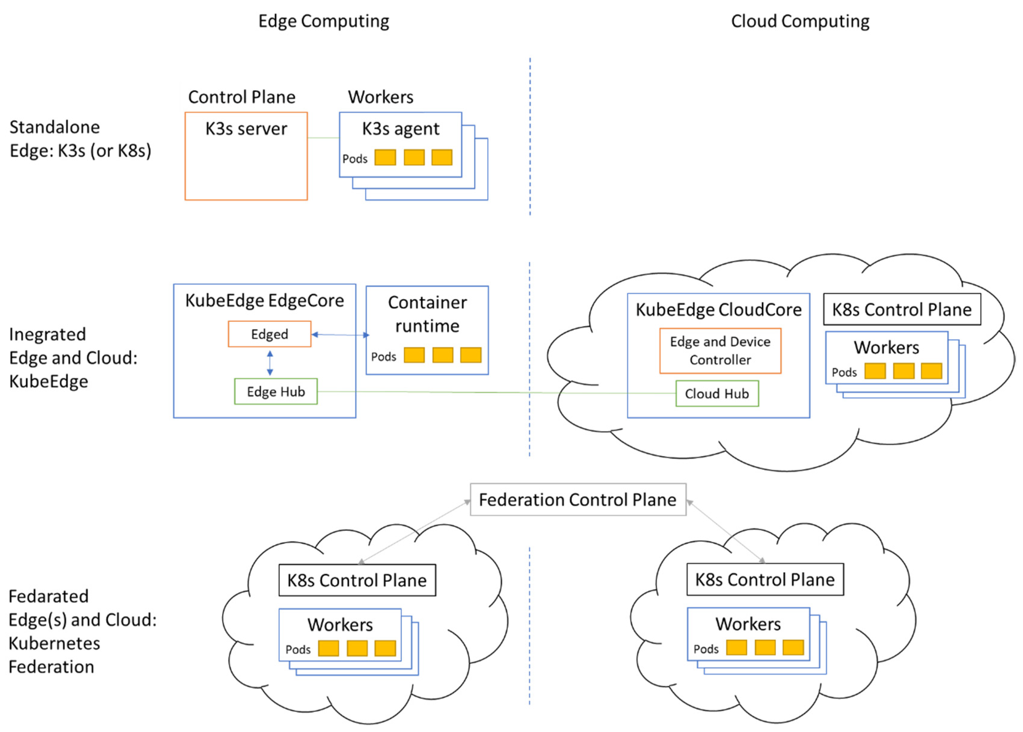
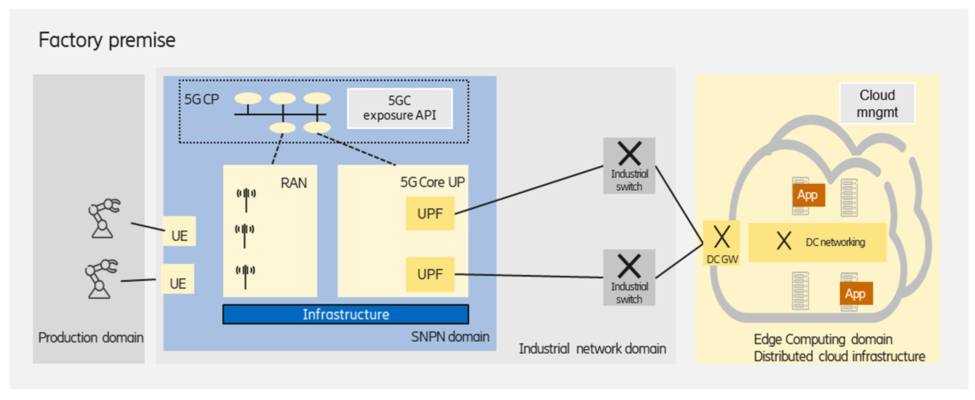


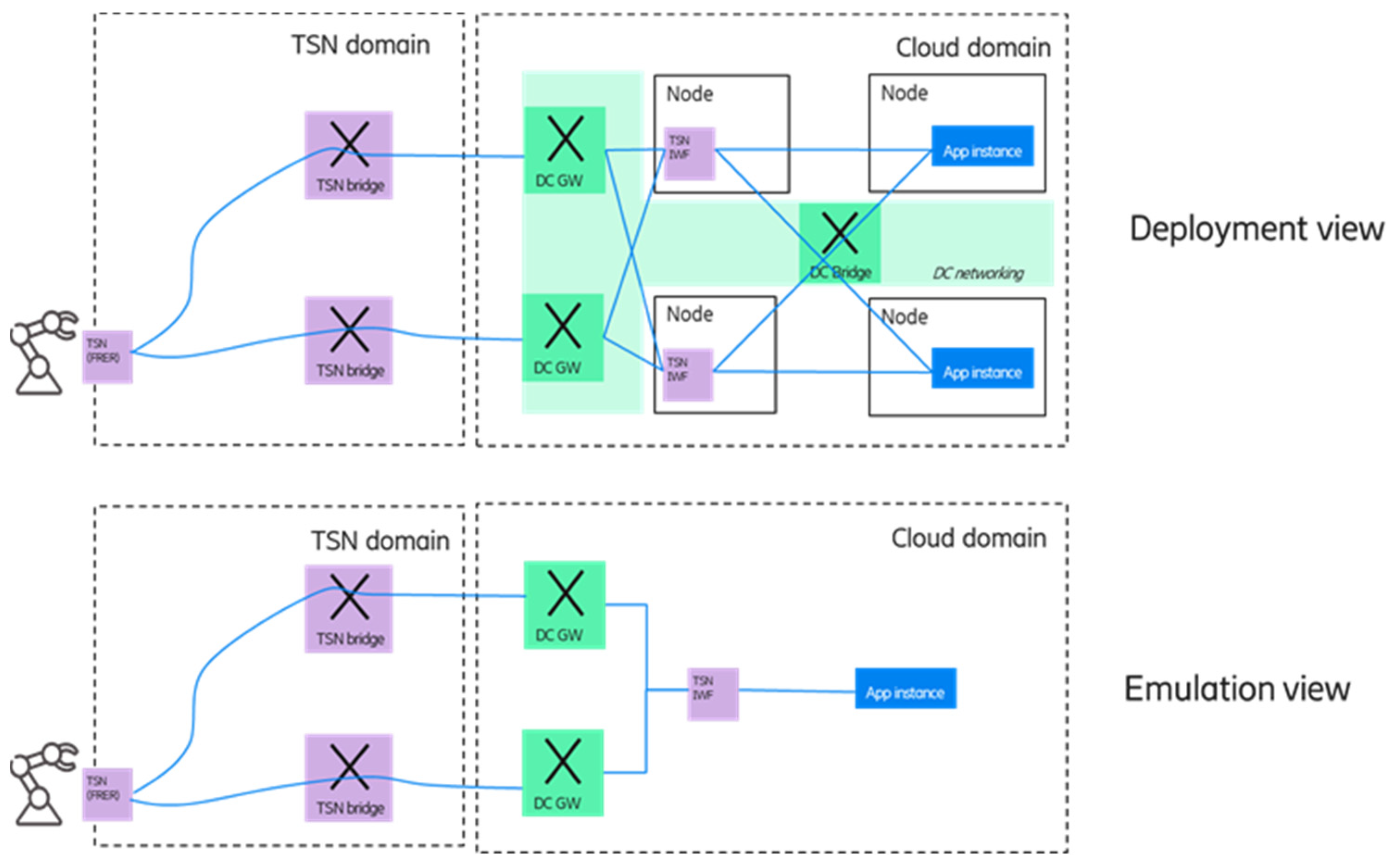
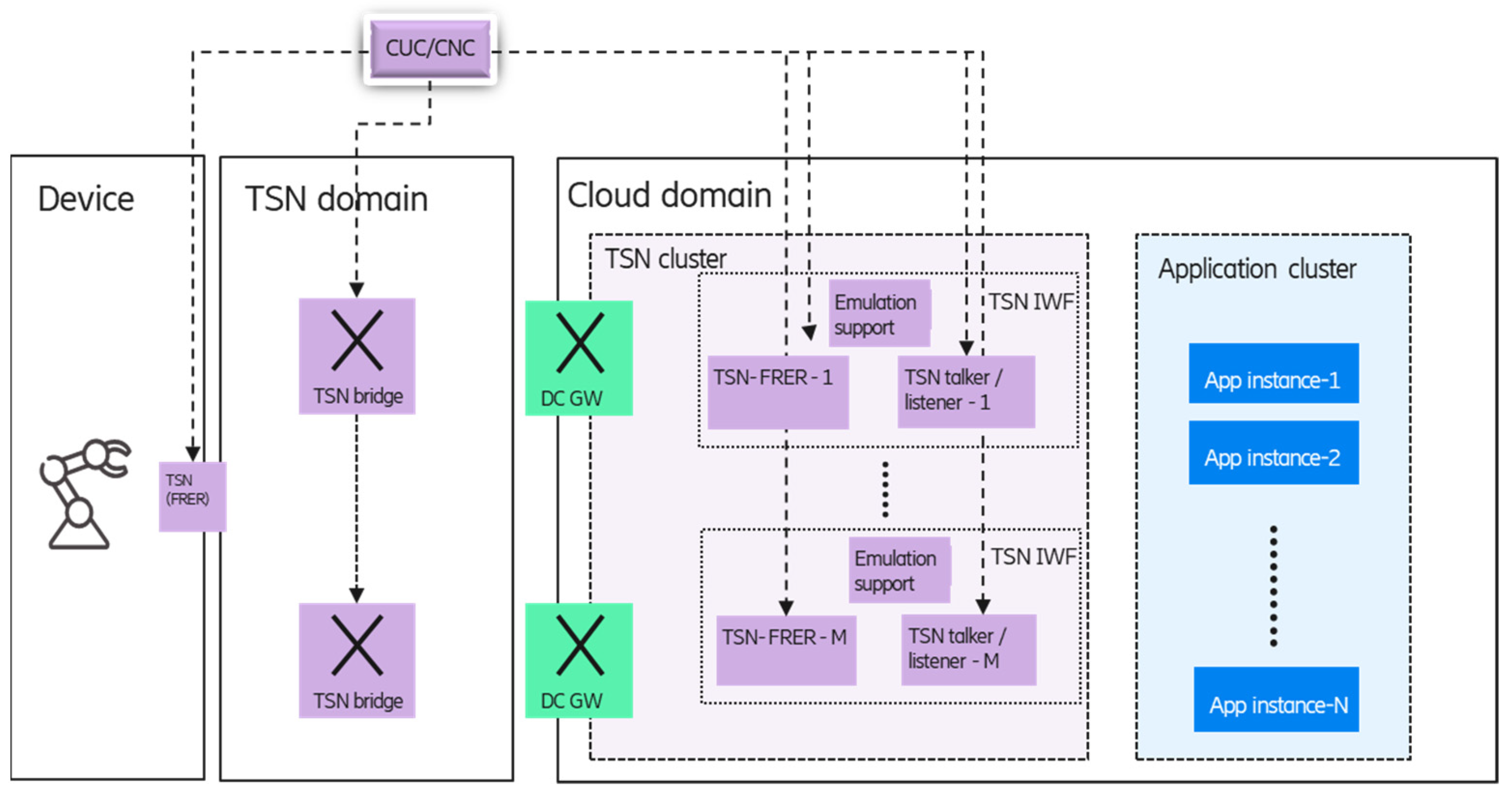


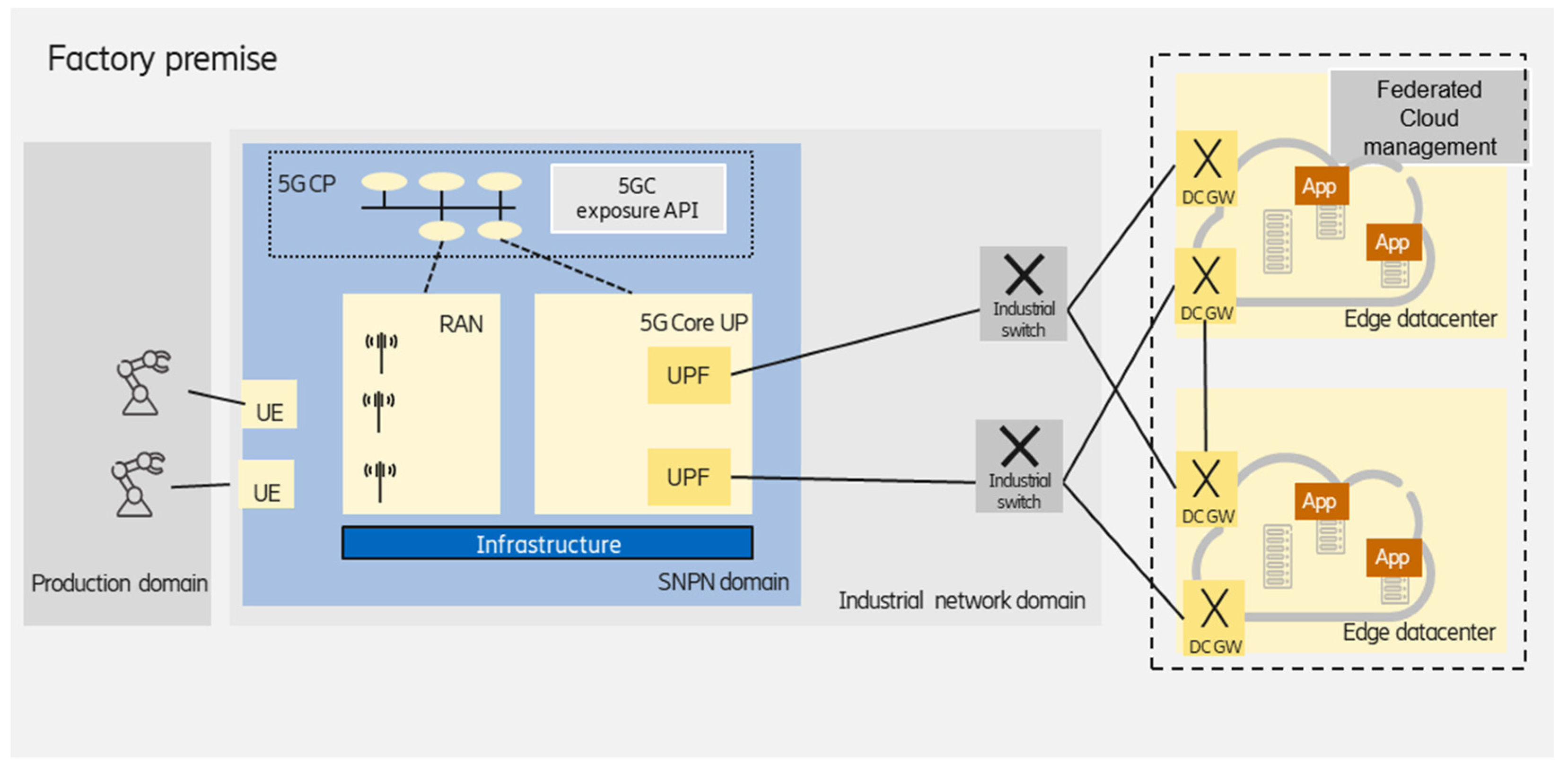
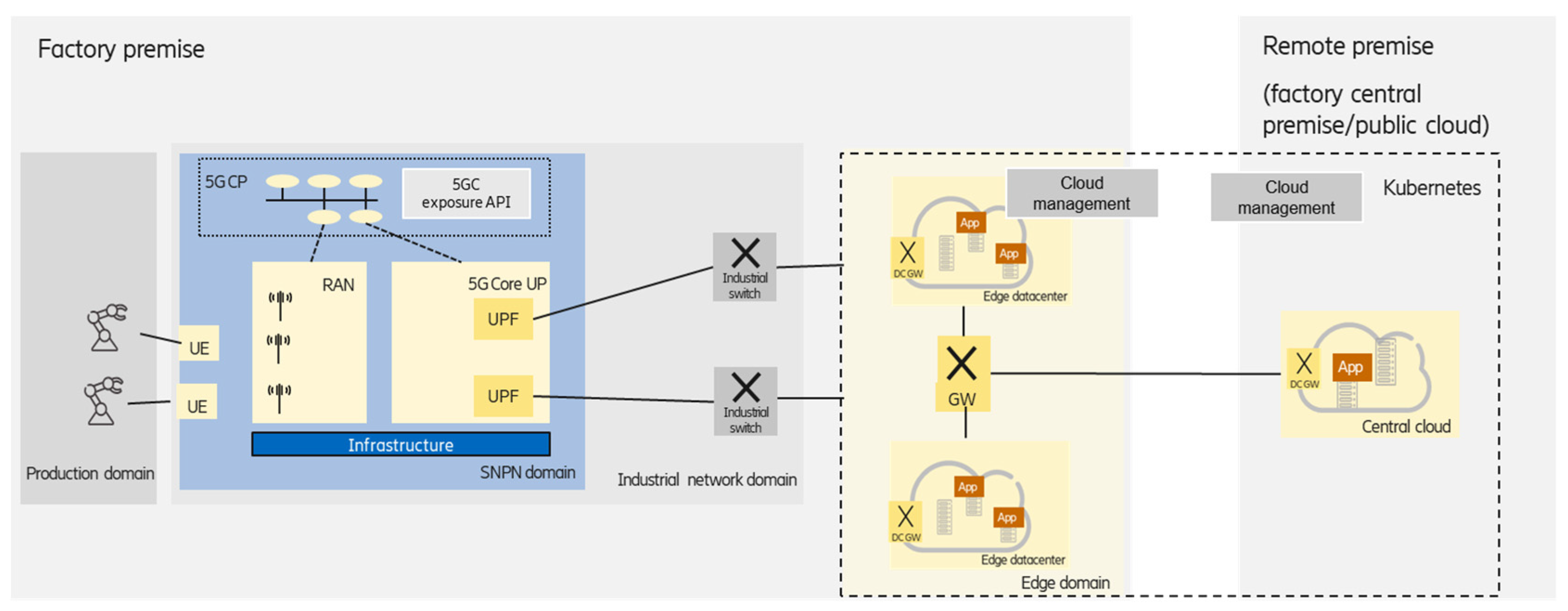
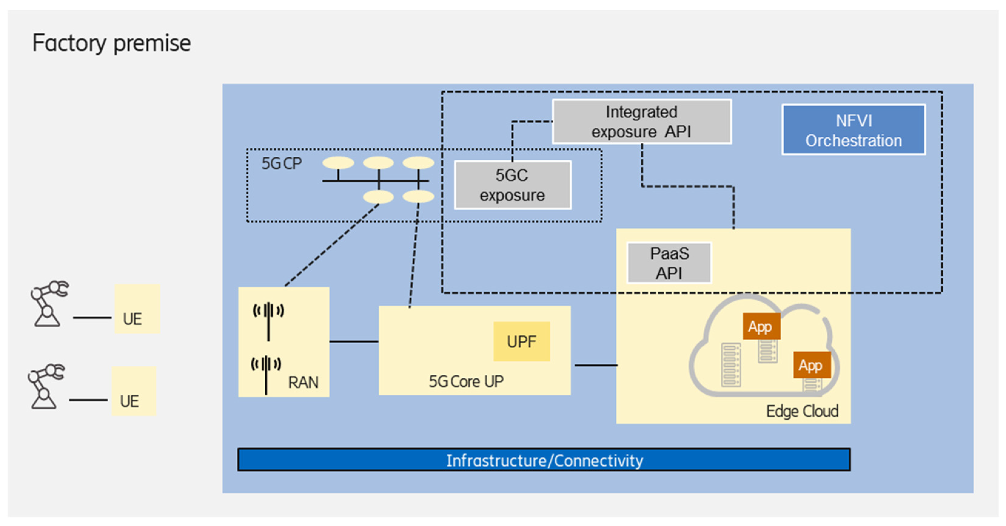
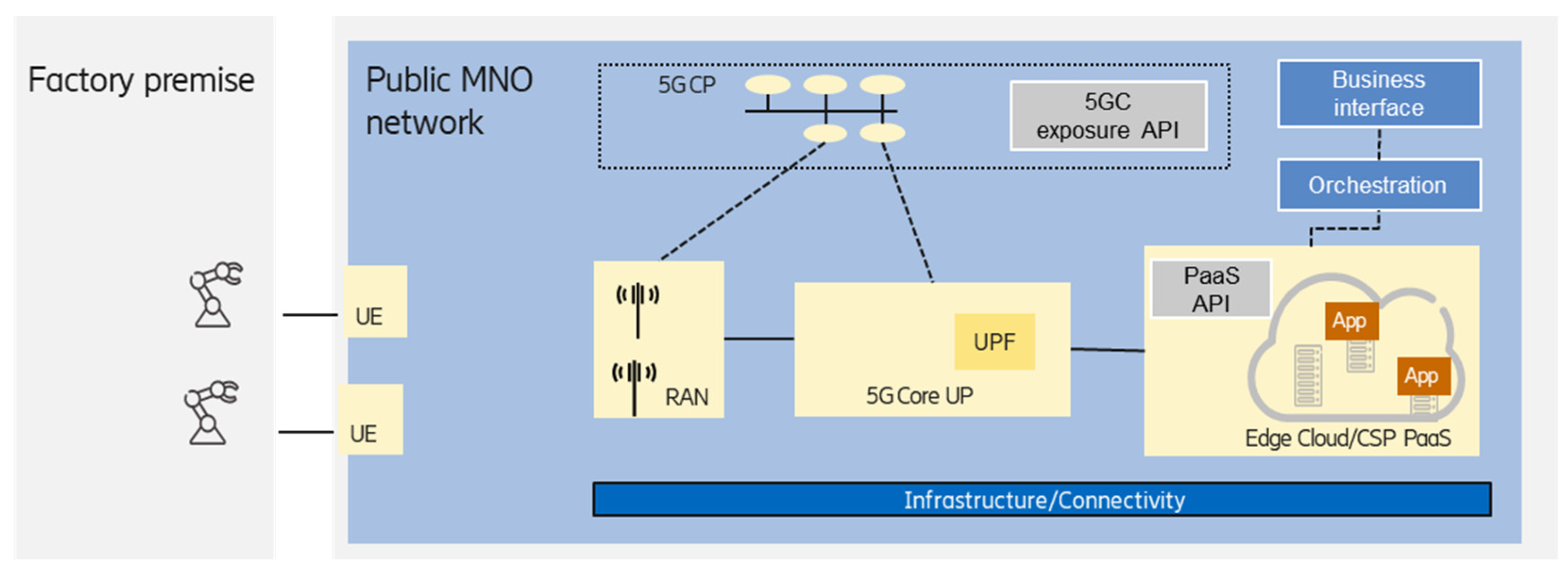
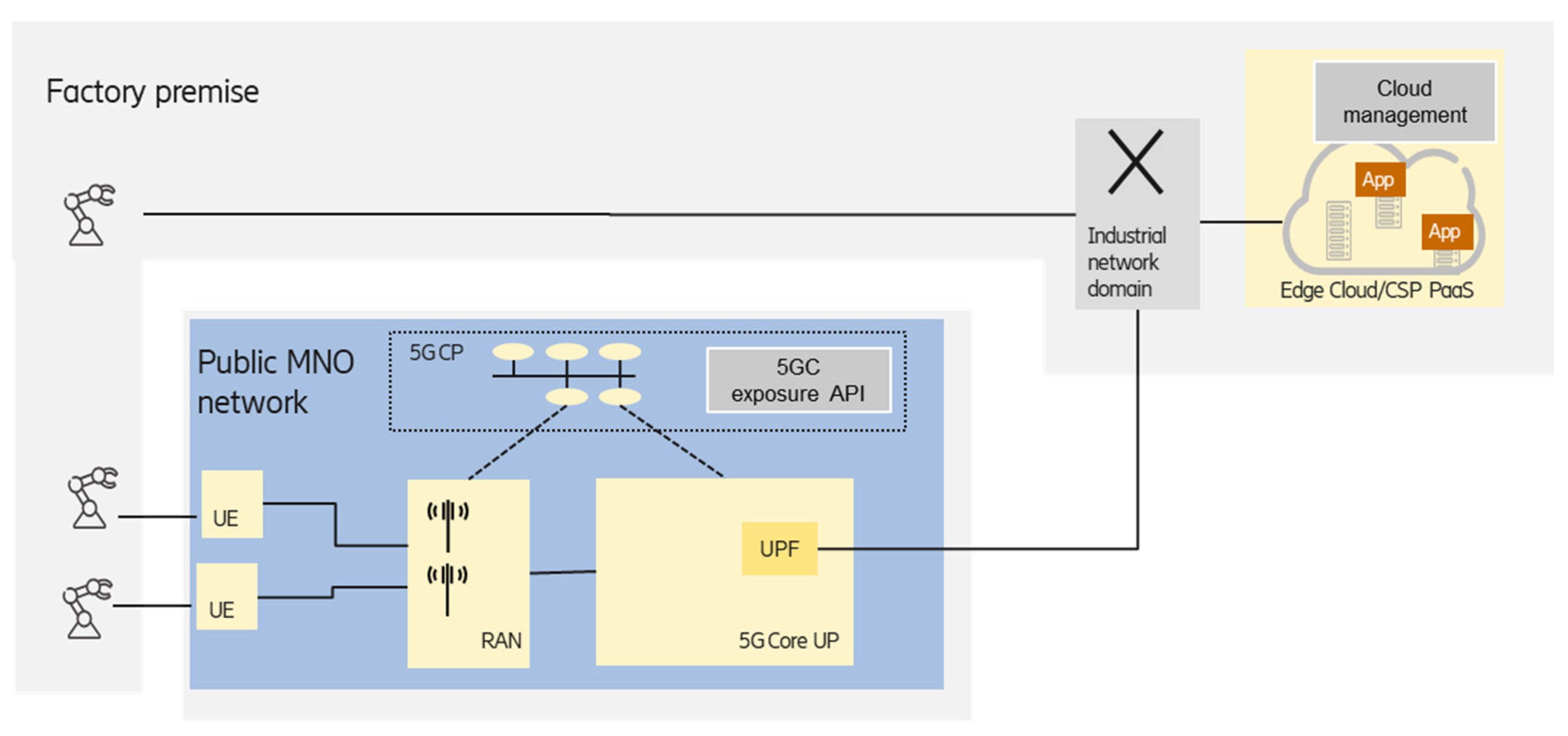
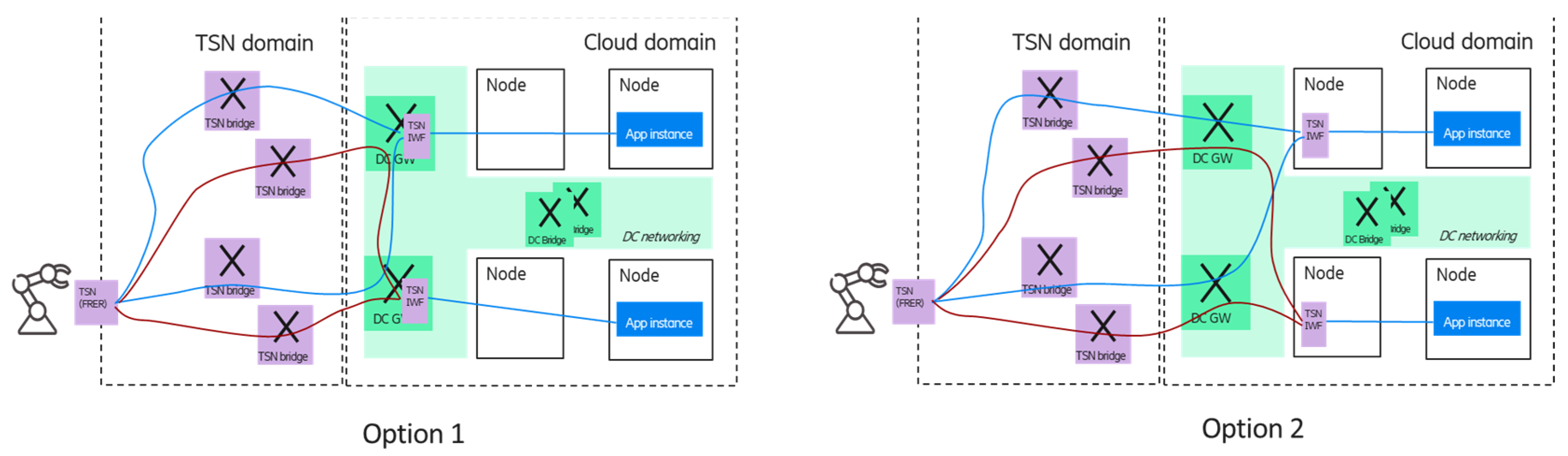
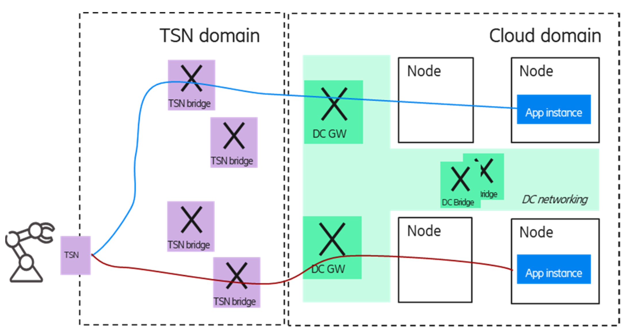
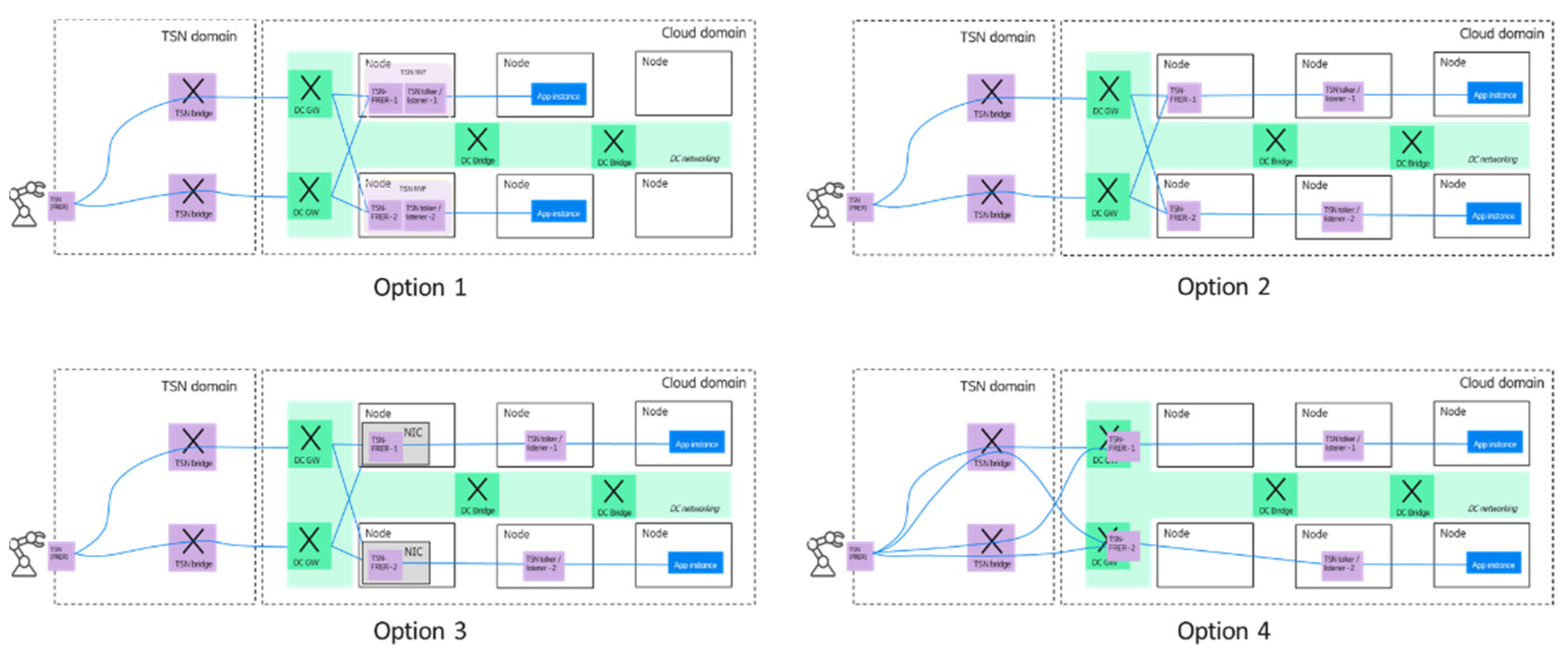