Article

An Active Voltage Coordinate Control Strategy of DFIG-Based Wind Farm with Hybrid Energy Storage System

College of Electrical Engineering, Sichuan University, Chengdu 610065, China
*
Author to whom correspondence should be addressed.
Electronics 2021, 10(24), 3060; https://doi.org/10.3390/electronics10243060
Submission received: 7 November 2021 / Revised: 5 December 2021 / Accepted: 6 December 2021 / Published: 8 December 2021

Abstract

:
In a power system with wind farms, the point of common coupling (PCC) usually suffers from voltage instability under large wind speed variations and the load impact. Using the internal converter of a doubly fed induction generator (DFIG)-based wind turbine to provide voltage support auxiliary service is an effective scheme to suppress the voltage fluctuation at PCC. To satisfy the reactive power demand of the connected grid, an active voltage coordinate control strategy with the hybrid energy storage system of the wind farm is proposed. The dynamic reactive power balance model is established to show the interaction between the reactive power limitation of the wind farm and the reactive power compensation demand of the grid. This indicates the initial conditions of the active voltage coordinate control strategy. According to the critical operating point and the operation state of the DFIG, the active and reactive power coordinate control strategy composed of active ω-β coordinate control and active β control is proposed to enhance the reactive power support capability and stabilize the grid voltage. To compensate the active power shortage, an auxiliary control strategy based on the hybrid energy storage system is introduced. The simulation results show that the proposed strategy can suppress the voltage fluctuation effectively and make full use of primary energy.

1. Introduction

The doubly fed induction generator (DFIG)-based wind turbine, as the main model in the current wind power industry [1], has been widely used because of the excellent control performance of the active and reactive power [2,3]. However, the increasing penetration of wind power brings more complex challenges to the connected system [4,5]. Long-distance and large-capacity high voltage transmission technology is generally adopted for wind farms which are located at the ends of the grid with an insufficient support capacity of the voltage [6,7]. The random fluctuation of wind speed and the impact load may lead to the voltage change at the point of common coupling (PCC) of the wind farm, the decrease in power quality, and the increase in equipment operation risk, which seriously threaten the voltage stability of the grid [8].
At present, many countries have formulated different standards for voltage control of wind farms [9,10,11]. The standard [12] in China specifies that the wind farm should be able to control the PCC voltage within 97~107% of the nominal voltage during normal operation. It is a common method in wind farms to stabilize the voltage of PCC by using reactive power compensation equipment such as capacitor and reactor banks [13], on-load tap changers [14], and static VAR compensators (SVCs) [15]. However, the reactive power compensation devices have the disadvantages of high cost and voltage overshoot. Therefore, considering the requirements of real-time reactive power compensation, using the internal converter of DFIG to provide voltage support auxiliary service is an effective scheme to reduce the adverse effects of wind speed variation and load impact.
With the steady growth of the wind power installed capacity [16], the active voltage support of wind farms to the power grid is required to ensure the stability of the connected system. The active voltage support refers to the ancillary service that wind farms can spontaneously participate in the reactive power regulation of the power grid and provide the support for the stable operation and the rapid recovery after faults of the power grid. Considering the operation demand of the power grid with the high proportion of wind power, it is of great significance to exploit the voltage support capacity of the wind farm to the power grid to improve the reactive power environment and promote the wind power consumption of the power system. The limitation of reactive power (LRP) of DFIGs was used to improve the voltage control strategy in [17,18], and the reactive power support capability of the wind farm was verified. A reactive power dispatch method was proposed in [19], in which the lifetime of the converter was considered to optimize the reactive power environment of the wind farm. The reactive power and voltage characteristics were adaptively adjusted according to the LRP of DFIG in [20] to improve the voltage support capability. However, the voltage problem of the wind farm caused by the rapid fluctuation of wind speed and the impact load cannot be solved by voltage control without considering the reactive power demand of the connected grid. In [21], the coordinated voltage control method was proposed, which was further improved in [22]. The available reactive power reserve of the wind farm was predicted, which enables the PCC voltage to be maintained within a reasonable range. The coordinate control methods of DFIG and other reactive power compensation devices were studied in [23] to improve voltage stability. However, the above methods ignore the influence of active power on LRP and voltage, which may lead to insufficient reactive power reserve in wind farms. The controller structure was modified to improve LRP in [18,24], while the active voltage control of the wind farm was formulated in [25] by adjusting the output active power according to the LRP. Nevertheless, the output active power reduction in a wind farm may lead to the waste of primary energy. Therefore, in the case of wind speed variation and load impact, it is necessary to propose a wind farm voltage control strategy considering voltage stability and energy utilization.
The application of energy storage provides a new method for optimizing the output power of the wind farm. In [26], an optimal operation strategy for active–reactive optimal power flow with embedded wind generation and battery storage was proposed, which was further improved in [27,28] and was applied to the electricity market in [29]. In [30], a distributed consensus control method for output power of DFIG and energy storage was proposed, which could realize energy management under different wind speeds. A system consisting of wind turbines, supercapacitors, and power converters was built in [31,32], and the supercapacitors can be used to reduce wind turbine output fluctuations. A hybrid energy storage system (HESS) is considered a new power supply technology. The application of HESS in DFIG can ensure the rational utilization of wind energy and maintain the active power of the wind farm. Generally, HESS includes lithium-ion batteries (LIBs), supercapacitors (SCs), etc. DFIG with HESS could satisfy a wide range of compensation requirements of PCC, that is, it can deal with the adverse effects of wind speed variation and load impact. Different from the wind farm level HESS, integrating the HESS technology into the wind turbine generator level could avoid high computational workload and centralized processing of a large amount of data. The structure of the HESS connected to the DC link in the DFIG could realize the timely dispatch and regulation of the output power in the wind turbine generator level. The structure of DFIG with HESS could optimize the operation characteristics of the DFIG, which is conducive to ensuring the stability of power in the wind farm and make the coordinated control of multiple units facilitate [33,34].
To make the DFIG-based wind farm support the voltage of PCC effectively, and make full use of the primary energy, this paper makes the following contributions:
(1)
A novel active voltage coordinate control strategy is proposed, which consists of the active and reactive power coordinate control strategy and the HESS-based auxiliary control strategy. The proposed control strategy enables the wind farm to spontaneously participate in the voltage regulation of the power grid. The more complete reactive power support auxiliary services of the wind farm could be provided based on the proposed strategy.
(2)
An active and reactive power coordinate control strategy of the wind farm is proposed. This strategy can satisfy the different operation states of the DFIG based on the active ω-β coordinate control and the active β control. Moreover, the LRP of the wind farm can be effectively improved to satisfy the reactive power demand of the connected system in the wind speed variations.
(3)
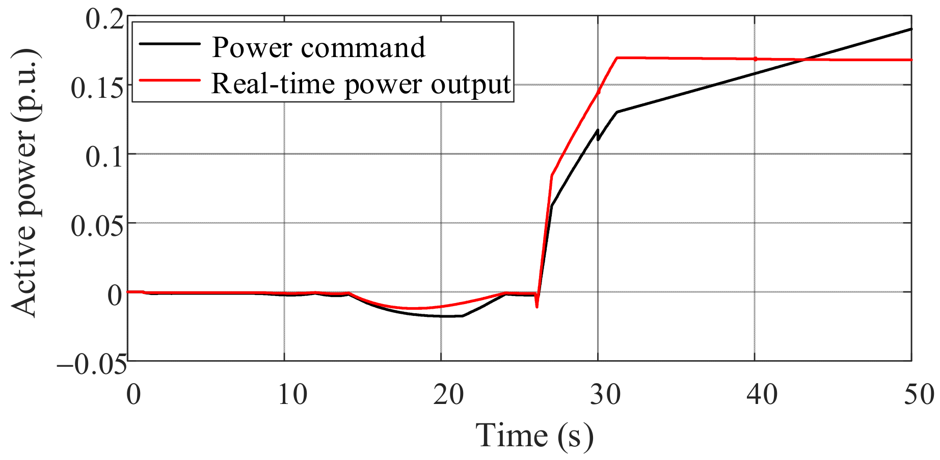
An auxiliary control strategy in DFIG based on the hybrid energy storage system (HESS) is proposed. The energy management in DFIG can be realized based on the proposed strategy. The reasonable utilization of the HESS reduces the power flow fluctuation of the local connected power grid and maintains the wind energy utilization. The proposed control strategy can respond to high frequency and low frequency commands to realize power compensation.
The rest of this paper is organized as follows: In Section 2, the operation characteristics of the DFIG-based wind farm are discussed. The structure of the active voltage coordinate control strategy is proposed in Section 3. The active voltage coordinate control strategy with HESS is proposed in Section 4. Section 5 discusses the simulation results of the proposed strategy, while the conclusion of the work is in Section 6.

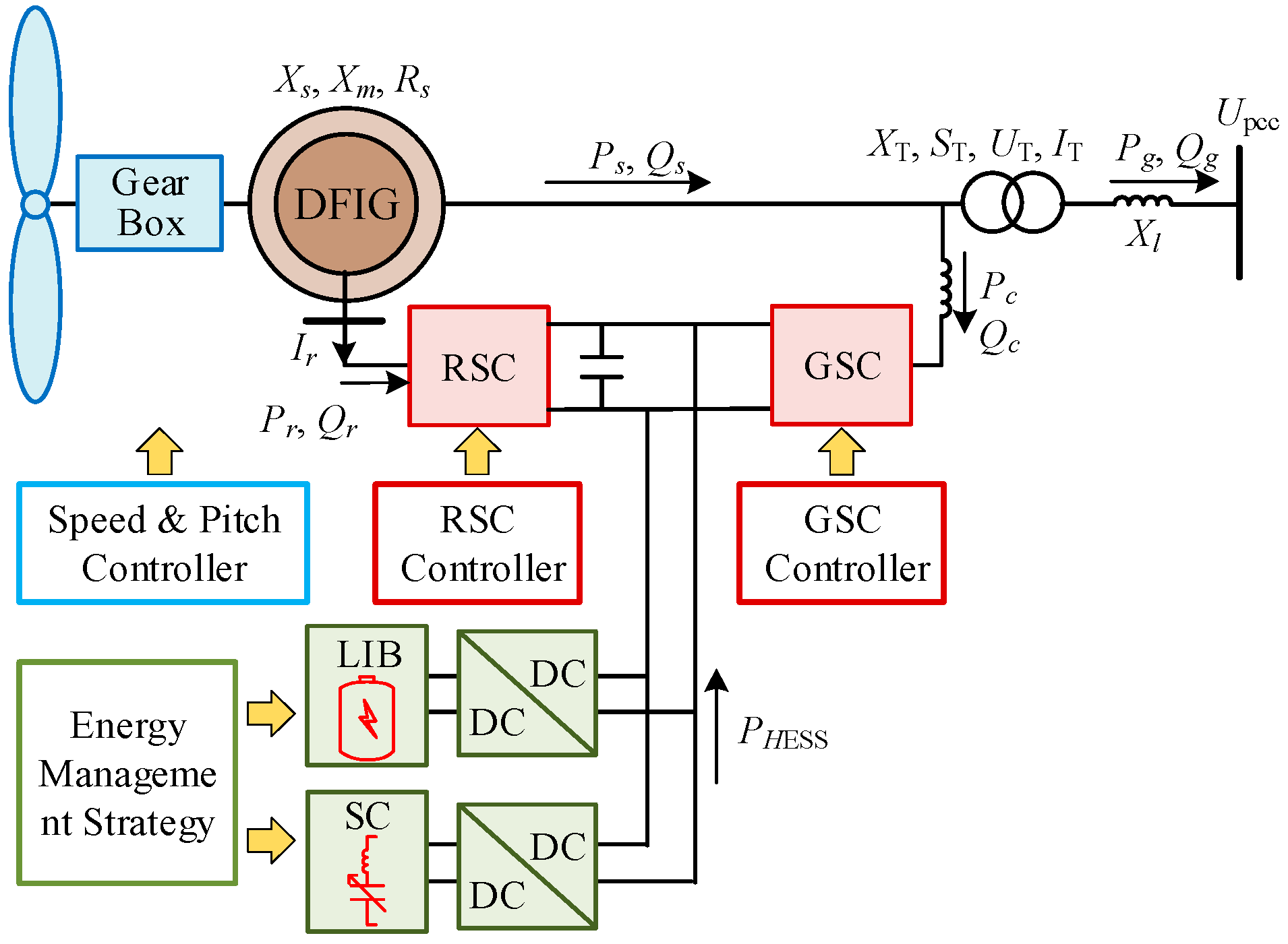
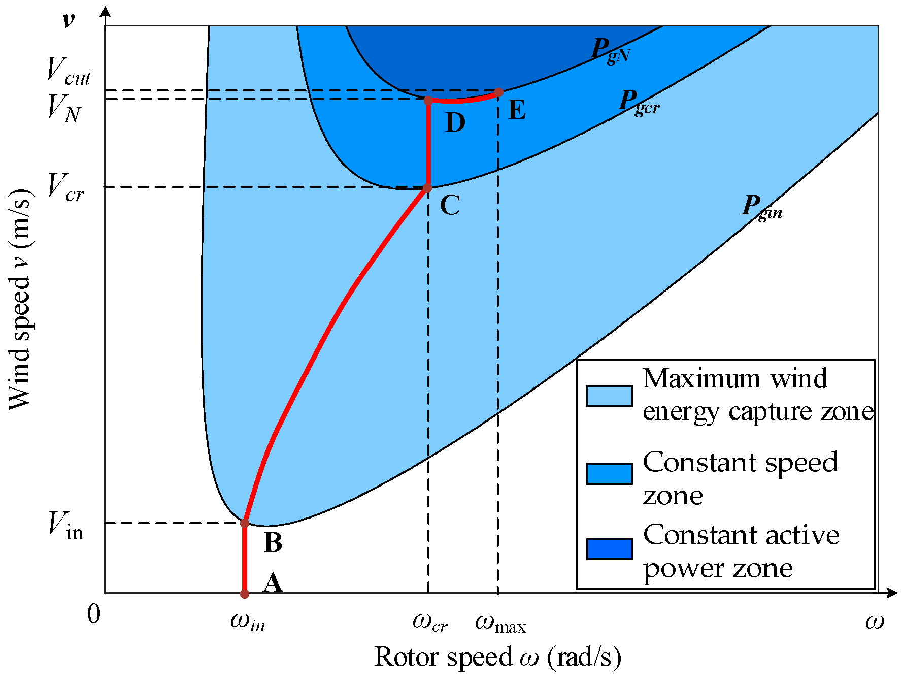
2. Operation Characteristics of DFIG-Based Wind Farm

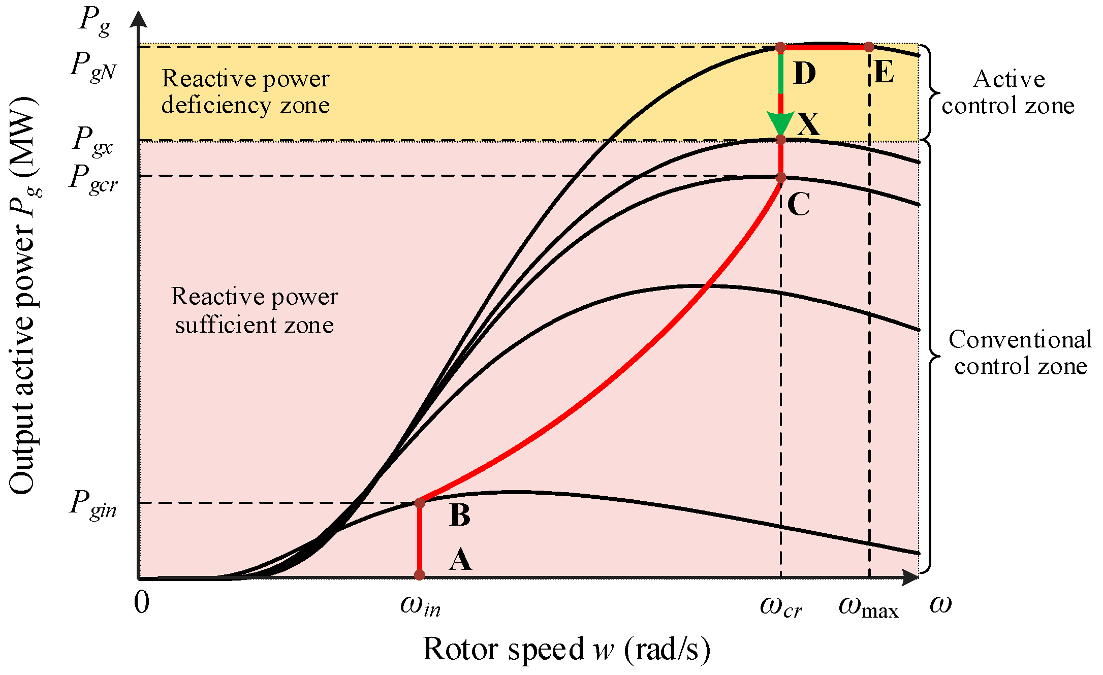
2.1. Power Characteristics of DFIG-Based Wind Turbine

Figure 1 presents the overall schematic diagram of a hybrid energy system consisting of the DFIG and the HESS. The main part of the proposed hybrid energy system structure is composed of three kinds of energy sources: DFIG, LIB, and SC. For the DFIG, the stator windings associated with the DFIG are connected to the grid directly, and the interface between the rotor and the AC system is a DC link composed of a back-to-back converter. By adjusting the rotor current, the rotor side converter (RSC) could realize the decoupling control of active power and reactive power in the DFIG stator side. Constant DC voltage control and constant reactive power control are applied to the grid side converter (GSC). For HESS, the LIB, and SC are connected with an additional Buck/Boost converter, respectively. It is assumed that the mechanical loss, copper loss, and iron loss of the DFIG with HESS are ignored to simplify the analysis.
The stator windings adopt the generator convention and the rotor windings adopt the motor convention. The direction shown in Figure 1 indicates the positive direction of the power flow, and the actual direction of the active and reactive power shall be determined according to the operation mode of DFIG. The wind turbine is used to capture the kinetic energy carried by the flowing air and convert it into mechanical energy. In the actual control system, there is a correlation between wind speed v, rotor speed ω, and the output active power Pg of a DFIG. The operation state and the control strategy of DFIG are different under wind speed variations. Because it is difficult to accurately detect the wind speed in operation, the corresponding optimal rotor speed command cannot be given directly. Therefore, the rotor speed closed-loop control is not used, and the output mechanical power of the wind turbine Pm is controlled to achieve indirect control of ω generally. Due to the neglect of DFIG system losses, the active power output from the wind turbine is equal to that from DFIG to the power grid, that is, Pm = Pg. The relationship among Pg, v, and ω of the DFIG is shown in Figure 2. The red curve indicates the power characteristics of the DFIG, which could be divided into four zones: the start-up zone (AB), maximum wind energy capture zone (BC), constant speed zone (CD), and constant active power zone (DE).
When v is less than the cut-in wind speed Vin, the DFIG operates in the AB zone and could be connected to the power grid at the appropriate time relying on the control system. When the value of v is between Vin and Vcr (the critical wind speed of the BC zone), the maximum power point tracking control could be realized and the optimal output power of DFIG Popt can be achieved. The aerodynamic model used to simulate wind energy acquisition by the wind turbine can be expressed as [35]:
P m = 1 2 ρ π R 2 C p ν 3
where ρ, R, λ, and β are the air density, the radius of wind turbine impeller, the tip speed ratio, and the pitch angle, respectively. The power coefficient Cp is a function of λ and β, and the variable λ can be defined as the ratio of the linear velocity at the tip of the wind turbine blade to the wind speed. When the DFIG operates in the BC zone and the wind speed changes, Popt can be acquired by maintaining the maximum value of Cp, namely, setting the pitch angle at the best angle and adjusting the rotor speed ω to make λ equal to the optimal value λopt. The corresponding rotor speed is ωopt. The optimal output power of DFIG based on (1) is expressed as:
P o p t = K o p t ω o p t 3
where parameter Kopt is the wind turbine correlation coefficient. The power constraint and rotor speed limit determine that the wind turbine is required to change working states with the variation of wind speed v.
As v increases to the range [Vcr, VN], where the variable VN denotes the rated wind speed, the steady-state operation point of DFIG is located in the CD zone. At this time, ω of DFIG has reached the critical rotor speed ωcr to avoid over-speeding and the pitch angle control could be used to maintain the rotor speed constant. Nevertheless, the output active power is less than the rated value PgN until the wind speed reaches VN. When v is greater than VN, DFIG ensures that the output active power does not exceed the limitation via increasing β, and operates in DE zone. The specific value of parameter ω is used to infer the operation state of DFIG in this paper. The rotor speed can be further adjusted by modifying the reference value of DFIG output active power.

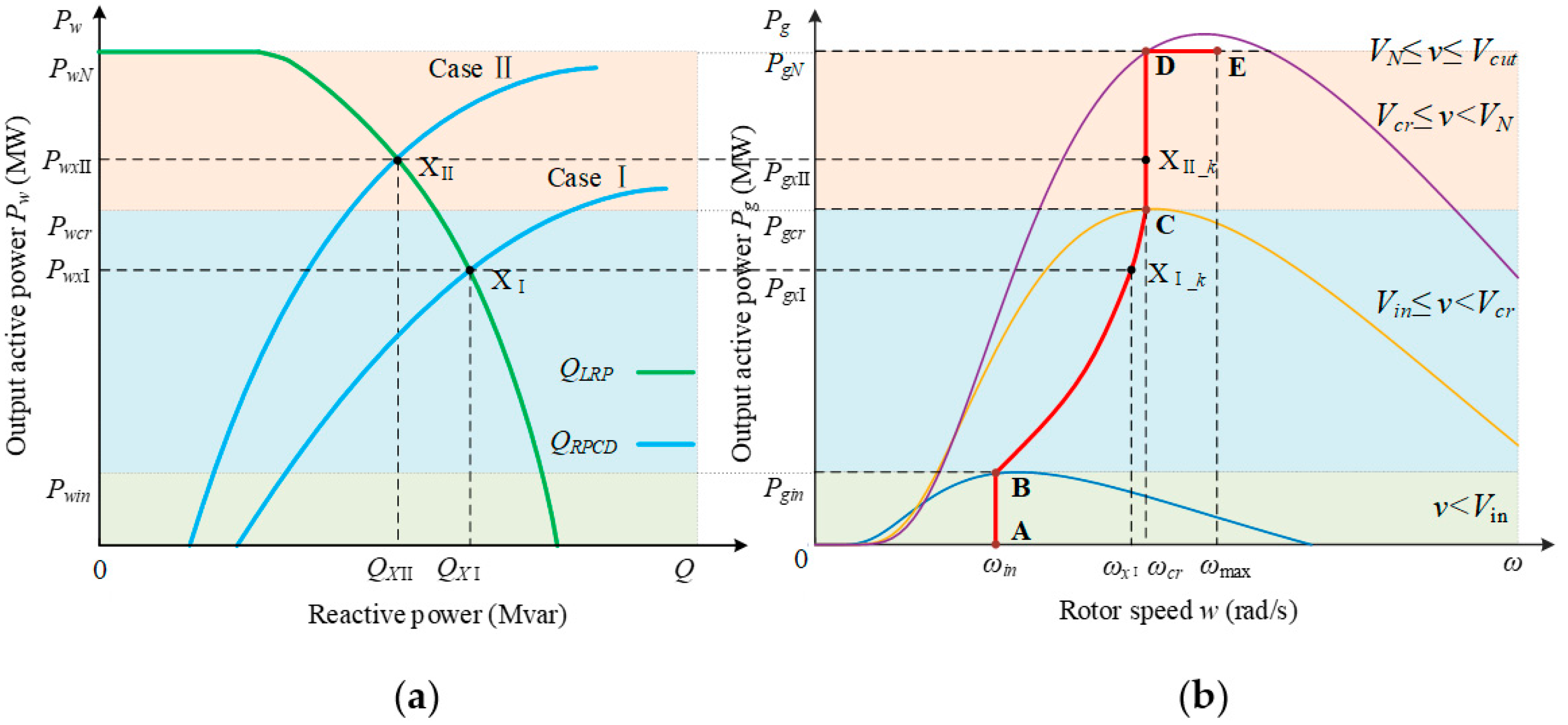
2.2. LRP of a DFIG-Based Wind Farm

The output active power of DFIG is mainly affected by wind energy, while the output reactive power is determined by the reactive power control scheme. The constraints of stator and rotor current are mainly considered in the stator side reactive power operation range of the DFIG. Based on the operation parameters, the equivalent circuit of DFIG with the stator branch, the rotor branch, and the excitation branch can be established. The effective value of DFIG rotor current Ir represented by the stator side output power can be expressed as:
I r = 2 ( R s 2 + X s 2 ) ( P s 2 + Q s 2 ) + 6 U s 2 ( P s R s + Q s X s ) + 9 U s 4 3 X m U s
where Xs and Xm are the stator reactance and the excitation reactance, respectively. Parameter Rs is the stator resistance. The amplitude of stator voltage is represented by the variable Us. Ps and Qs denote the stator side active power and reactive power of the DFIG, respectively. The power output range of the DFIG stator side can be shown as:
( P s + 3 U s 2 R s 2 ( R s 2 + X s 2 ) ) 2 + ( Q s + 3 U s 2 X s 2 ( R s 2 + X s 2 ) ) 2 = 9 U s 2 X m 2 I r 2 4 ( R s 2 + X s 2 )
Limited by the capacity of the RSC, the maximum allowable value of rotor current in long-term operation is Irmax. Without considering the stator resistance, the feasible range of the stator power is shown as follows:
P s 2 + ( Q s + 3 U s 2 2 X s ) 2 ( 3 U s X m I r max 2 X s ) 2
Under steady-state circumstances, whether DFIG is in super-synchronous or sub-synchronous operation, the stator side is in a generation state. The trajectory of Ps and Qs is an approximate semicircle with ( 0 , 3 U s 2 / 2 X s ) as the center and 3 U s X m I r max / 2 X s as the radius. The stator side reactive power limitation of DFIG with certain Ps is expressed as follows [36]:
{ Q s max = 3 U s 2 2 X s + ( 3 U s X m I r max 2 X s ) 2 P s 2 Q s min = 3 U s 2 2 X s ( 3 U s X m I r max 2 X s ) 2 P s 2
Different from the stator side, the grid side reactive power limitation Qcmax and Qcmin are determined by the slip rate s and Ps, shown as:
{ Q c max = S c 2 ( s 1 s P s ) 2 Q c min = S c 2 ( s 1 s P s ) 2
where Sc is the MVA capacity of GSC. Considering the capacity of reactive power generation at stator side and grid side, the reactive power limitation of the DFIG can be presented as:
{ Q g max = Q s max + Q c max Q g min = Q s min + Q c min
Assume that the number of DFIGs in the wind farm is n, and the output active power of the wind farm Pw is obtained from the sum of Pg of each DFIG. The actual output reactive power of the wind farm shall consider the reactive power loss. The reactive power loss of a wind farm is mainly composed of box-type transformers, step-up transformers, collecting lines, and transmission lines. The LRP of a wind farm can be expressed as:
Q L R P = i = 1 n Q g i max j = 1 J ( ( P T j 2 + Q T j 2 ) X T j U T j 2 + S T j I z j % ) k = 1 L ( P l k 2 + Q l k 2 U l k 2 X l k )
where J and L are the number of transformers and lines in the wind farm. Parameters PT and QT are the active power and reactive power passing through the transformer, respectively. Parameters XT, ST, UT, and Iz refer to the equivalent reactance, the rated capacity, the rated voltage, and the no-load current of the transformer, respectively. The percent sign is the conventional expression of the transformer. Parameters Pl and Ql are the active power and reactive power passing through the transmission line, respectively. Parameters Ul and Xl are the rated voltage and reactance of the line. The second and third terms in (9), respectively, represent the sum of reactive power losses estimation of transformers and lines in the wind farm.
The output active and reactive power range of the wind farm can be approximately shown in Figure 3. The green line in Figure 3 describes the LRP function based on Pw. It is obvious that the LRP of the wind farm can be improved by reducing the value of Pw.

2.3. RPCD of the Connected Power Grid

The power flow variation of the wind farm may lead to PCC voltage Upcc fluctuation. Although the reactance of high-voltage transmission lines is much greater than the resistance, the influence of wind farm active power output variation on Upcc should be considered because the active power output of the wind farm far outweighs the reactive power. The load impact of the power grid may also cause the instability of the PCC voltage. The voltage Upcc considering the influence of the wind farm output power, the electrical distance, and the impact load can be represented as:
U pcc = F ( P w ,   Q w ,   Δ Q B ,   X L ,   R L ,   U G )
where Pw and Qw are the output active power and reactive power of the wind farm, respectively. Parameter ΔQB is the charging power of the outgoing transmission line of the wind farm. Variable X L and R L , respectively, represent the equivalent reactance and resistance of the wind farm outgoing transmission lines with PCC as the terminal, while variable U G is the terminal voltage of the power grid.
According to (10), voltage Upcc is strongly related to reactive power Qw and active power Pw. It is necessary to explore the reactive power potential of the wind farm deeply in a steady state and energetically inject reactive power into the power grid according to the RPCD when the wind speed fluctuates, so as to realize the active voltage coordinate control of PCC. The RPCD of the power grid related to the target value Upcc_tar of PCC voltage can be expressed as:
Q R P C D = G ( U pcc _ tar ,   P w ,   Δ Q B ,   X L ,   R L ,   U G )
It should be noted that the RPCD of the power grid is affected by the grid structure of the wind farm connected to AC main network. Equations (9) and (11) constitute the dynamic reactive power balance model of the wind farm and the connected power grid, which indicate the interaction between the reactive power output capacity of the wind farm and the reactive power demand of the grid.

3. Structure of the Proposed Active Voltage Coordinate Control Strategy

Based on the dynamic reactive power balance model, the LRP–RPCD operation curve could be acquired. The interaction between LPR and RPCD is revealed in Figure 3a, and the wind farm could compensate the reactive power required by the grid when QLRPQRPCD. The intersection X indicates that QLRP = QRPCD, which means that the reactive power output capacity of the wind farm can precisely satisfy the grid requirements for voltage control. If the RPCD changes beyond the feasible range, that is, QLRPQRPCD, the LRP of the wind farm has difficulty satisfying the demand of voltage control and the voltage instability may be induced by the insufficient reactive power of the grid. Under this circumstance, the operating state of the wind farm is required to be adjusted positively. From the trend of the RPCD curve and LRP curve, the active power reduction in the wind farm could improve the LRP of the wind farm, and the reactive power potential of the wind farm can be further explored, so as to maintain the voltage stability of PCC.
The operation characteristics of the wind farm can be represented by the superposition of DFIGs. It is obvious that the critical operation point X represents the reactive power reserve characteristics of the wind farm. Since Pw of a wind farm is closely related to the output power of DFIGs, there is a mapping relationship between critical operation point X and the operation state of the kth unit shown in Figure 3b. Because of the different interactions between the wind farm and the grid, the intersection X may correspond to the different operating states of the DFIG. In case I, when the output active power of wind farm is PwxI and the corresponding DFIG output active power is PgxI with the real-time rotor speed ωxI calculated by (2), DFIG operates in the BC zone. While for case II, the DFIG works at a constant speed and the corresponding output active power of wind farm is PwxII. The rotor speed ωxII of the DFIG is corresponding to point X. The physical meaning of ωx can be expressed as the rotor speed when the reactive power capacity of the wind farm meets the reactive power demand of the power grid. The analysis of the relationship between point X and the operation state of the DFIG contributes to further exploring the active voltage support control strategy of the wind farm under different operation conditions.
To suppress the voltage fluctuation of PCC caused by the wind speed variation and the load impact, the existing LRP of the wind farm is utilized first. When the reactive power reserve of the wind farm is insufficient, an active voltage coordinate control strategy is proposed to adjust the operation state of the wind farm. The structure of the proposed control strategy is shown in Figure 4, which could enhance the support capacity of the wind farm to the connected power grid under voltage fluctuate conditions. As shown in Figure 4, if the LRP of the wind farm is inadequate to meet the RPCD of the system, the active voltage coordinate control needs to be activated, and the critical operating point X can be used as the starting point of the active voltage coordinate control. The interaction between the source and the grid is considered by active voltage coordinate control. The proposed active control strategy could adjust the output power of the DFIG to stabilize the voltage, which can make full use of the primary energy and suppress the voltage fluctuation of PCC caused by the wind speed variation and the impact load.

4. Active Voltage Coordinate Control Strategy with HESS

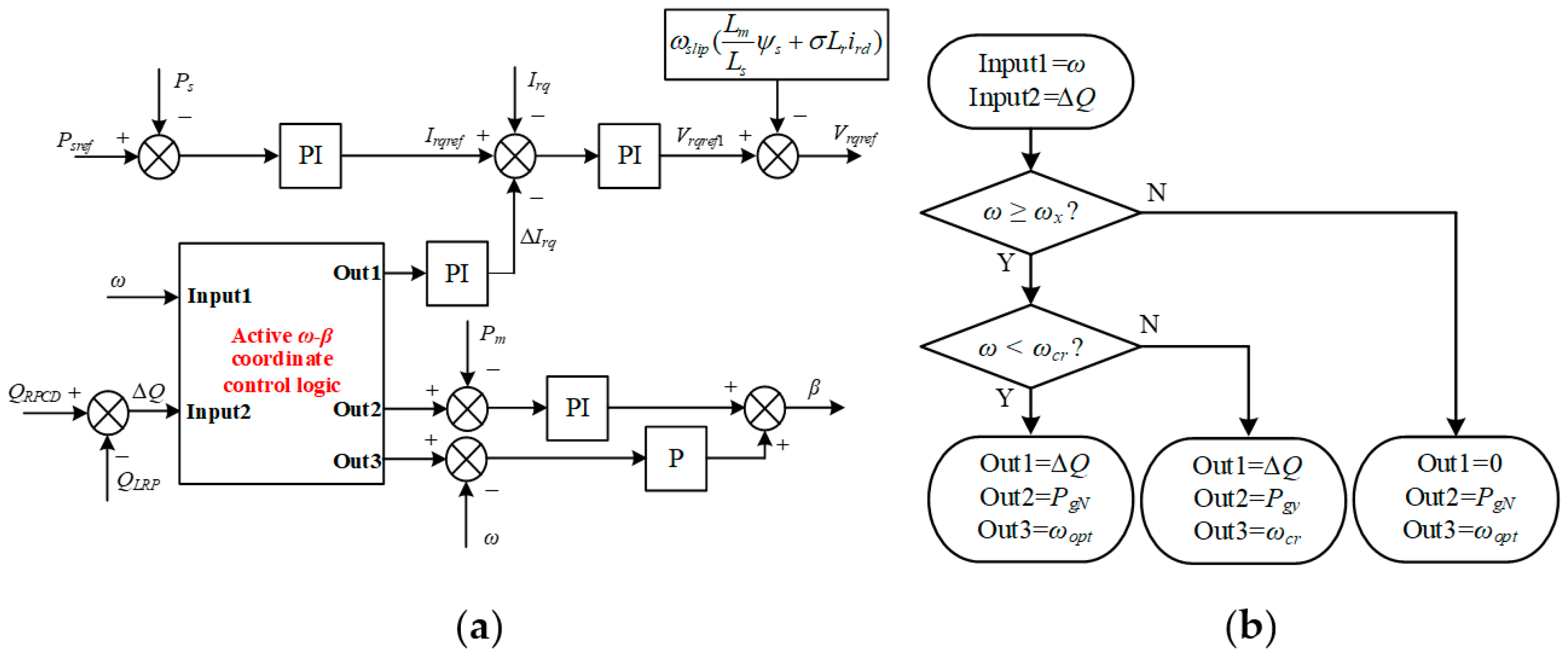
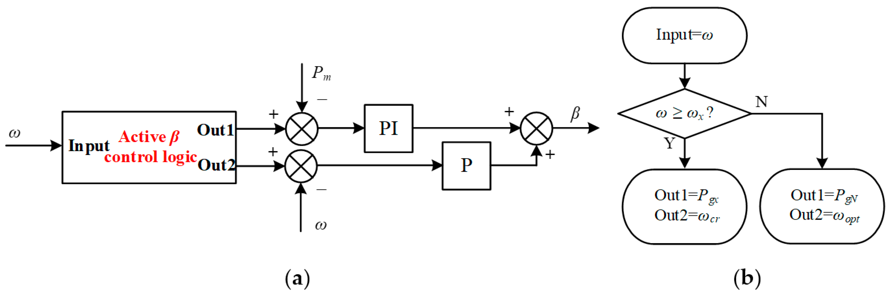
4.1. Active and Reactive Power Coordinate Control Strategy

When point X is located in the BC zone, the rotor speed satisfies ωinωx < ωcr, and point X divides the operation zone of DFIG into two parts, that is, reactive power sufficient zone and reactive power deficiency zone. The rotor speed satisfies the constraint, ωinω < ωx, in the reactive power sufficient zone. Due to the LRP of the wind farm being greater than the RPCD of the grid, the wind farm can output enough reactive power to support the PCC voltage by setting the appropriate reference value of the reactive power outer loop control. The reactive power distribution scheme represented by the reactive power reference value Qgiref of the ith DFIG is formulated according to the proportion of the reactive power limitation Qgimax to QLRP, shown as:
Q g i r e f = Q g i max Q L R P Q R P C D
The reactive power distribution scheme means that when the power grid needs a wind farm to provide reactive power support, the LRP of each DFIG is used as the basis to distribute the reactive power output assignment of the unit. This scheme ensures that the operating parameters of DFIG do not exceed the limitation. From the perspective of response speed, the DFIG gives priority to the reactive power generation of GSC. For the reactive power distribution of the ith DFIG, the following two circumstances need to be considered. When Qgiref is less than Qcimax of the ith DFIG, set the reactive power reference value Qciref of GSC equal to Qgiref, while the RSC operates in the original state. When Qgiref exceeds Qcimax, the variable Qciref is taken as the limit value, while the stator side of DFIG generates reactive power to supplement the residual reactive power demand. The reactive power distribution is completed in the control system of each DFIG, expressed as:
{ Q c i r e f = Q g i r e f Q g i r e f Q c i max Q c i r e f = Q c i max & Q s i r e f = Q g i r e f Q c i max Q g i r e f > Q c i max
when ωxω < ωcr, the ith DFIG works in the reactive power deficiency zone. With the increase in the wind speed, the reactive power capacity of the wind farm decreases gradually, which is difficult to satisfy the reactive power demand of the system. Therefore, an active ω-β coordinate control strategy based on the LRP–RPCD operation curve is proposed, which could reduce the PCC voltage drop by combining the active and reactive power capacity of the wind farm. The active ω-β coordinate control strategy is used by the RSC and the wind turbine. According to (12) and (13), the reference values of reactive power in the active voltage coordinate control can be obtained. Figure 5 shows the power variation characteristics of DFIG with the active ω-β coordinate control strategy based on the LRP–RPCD operation curve. The original power curve is shown by the red solid line, while the blue line is the power characteristics curve under the active control.
Due to the function of the additional control, the operation points on the blue line in Figure 5 could satisfy QLRP = QRPCD, which means that the wind farm can adjust the PCC voltage according to the command value based on considering the reactive power capacity. When ω increases to ωcr and the output active power just makes QLRP = QRPCD, the corresponding operation point of the DFIG is the final state, as the point Y in Figure 5. Parameter Pgy is calculated based on (1).
However, with the further increase in the wind speed, it is difficult to reduce the output active power only under the additional control. The pitch angle control is adopted in this stage. Pgy is the reference value of pitch compensation. The pitch angle control in the active ω-β coordinate control strategy is expressed in Figure 6a, and the control logic is shown in Figure 6b. Because of the pitch angle intervention, the operation points will converge to point Y, as shown in the green dashed line in Figure 5.
When ωx = ωcr, the critical operating point X is located in CD zone of the DFIG. When ω is less than ωx, the voltage control can be realized by adjusting the reactive power output of the DFIG owing to the sufficient reactive power margin. When ω rises to ωcr, the pitch angle control is used to further reduce the active power of DFIG and the active β control strategy is proposed. The power variation characteristics of a DFIG under this circumstance are shown in Figure 7.
Due to the sufficient reactive power reserve of the wind farm, the critical operating point X can be used as the final operating point of the active β control strategy. The compensation reference value of the pitch angle control is Pgx, and the operation point converges to point X finally. The active β control strategy and the control logic are expressed in Figure 8. To ensure the equipment safety, DFIG operation in the DE zone should be avoided.

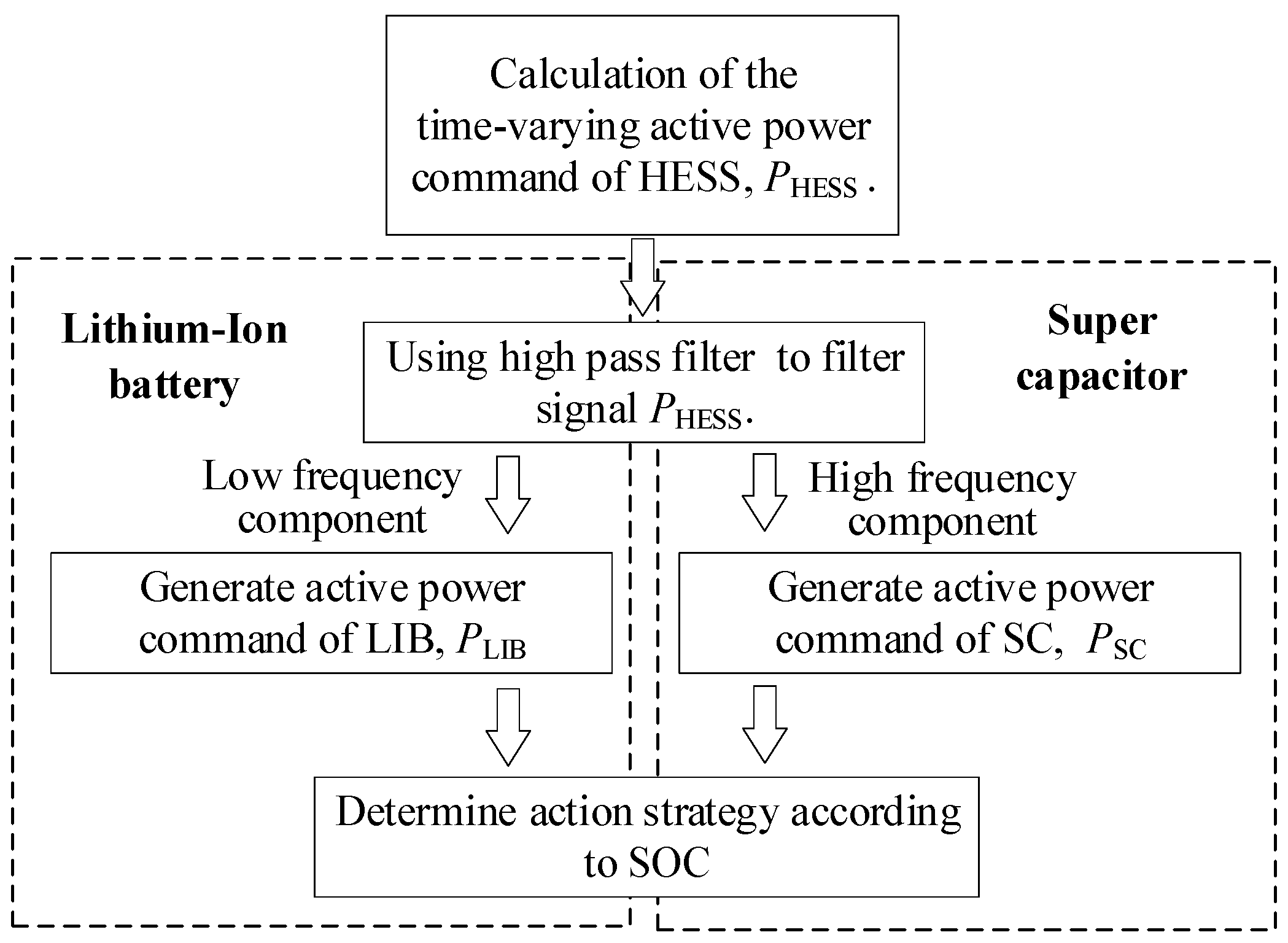
4.2. HESS-Based Auxiliary Control Strategy
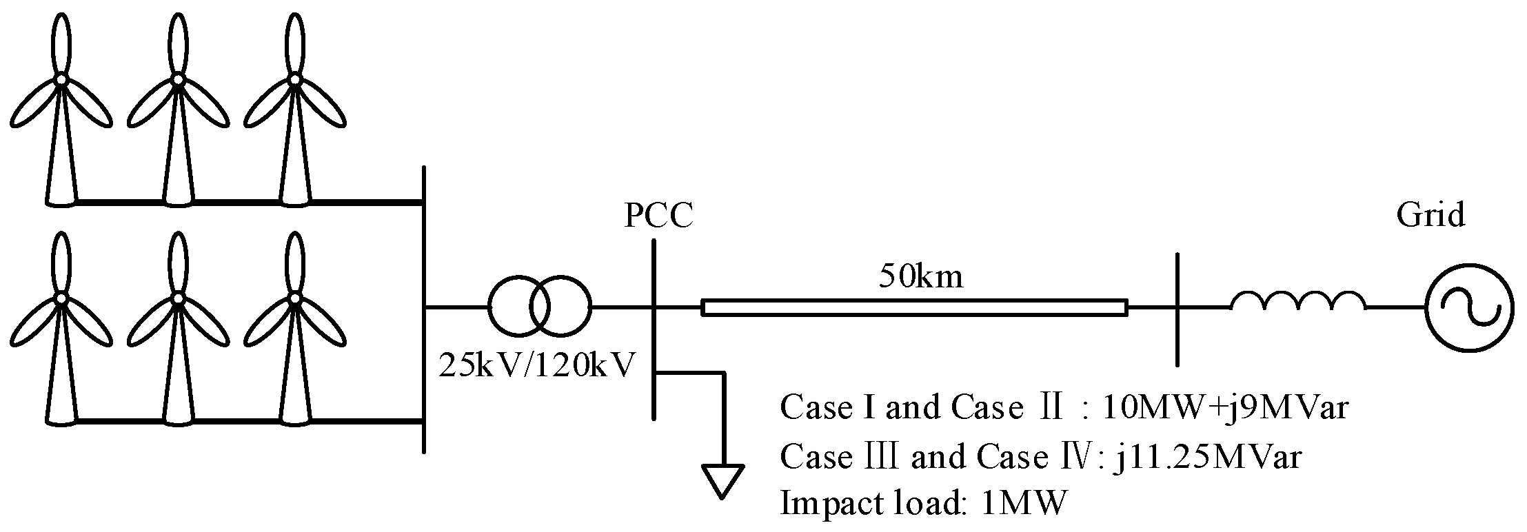
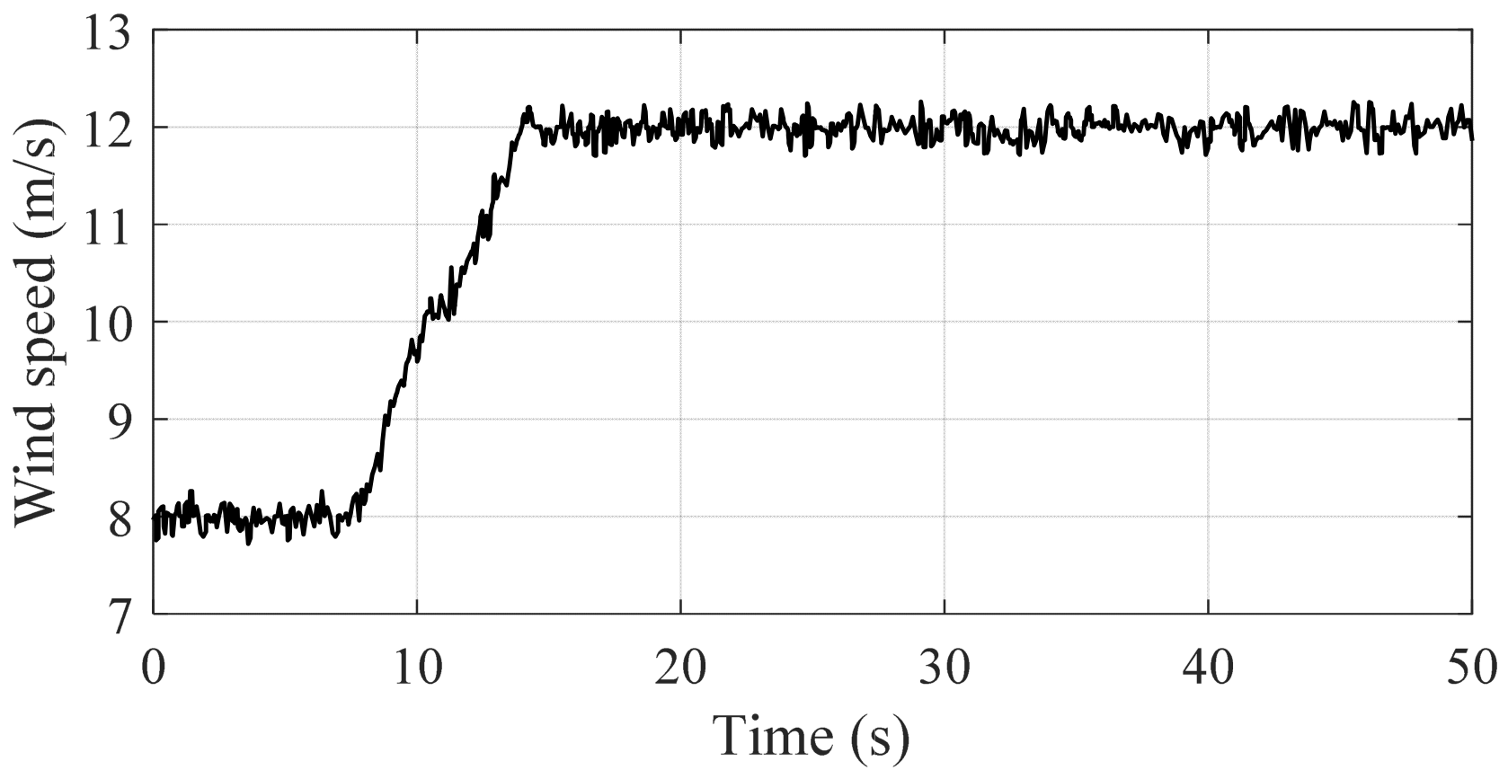
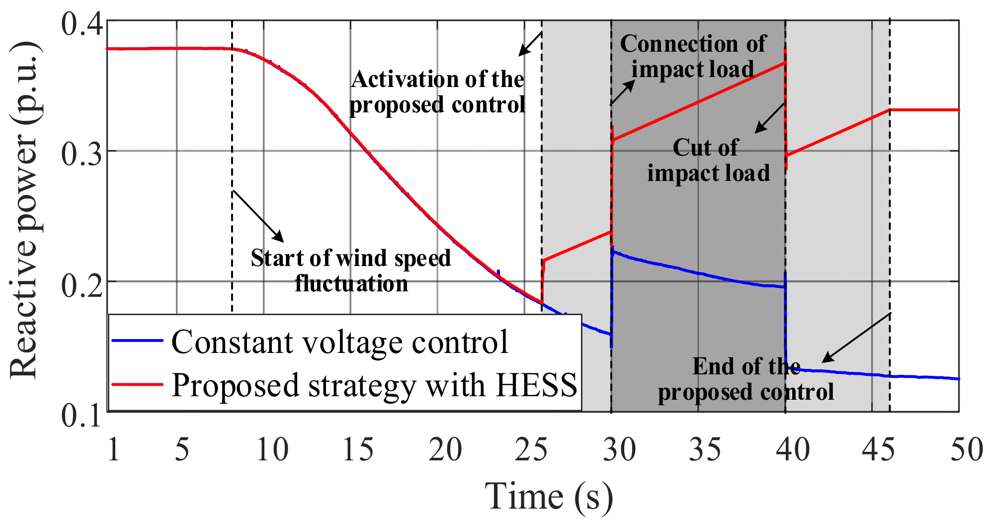
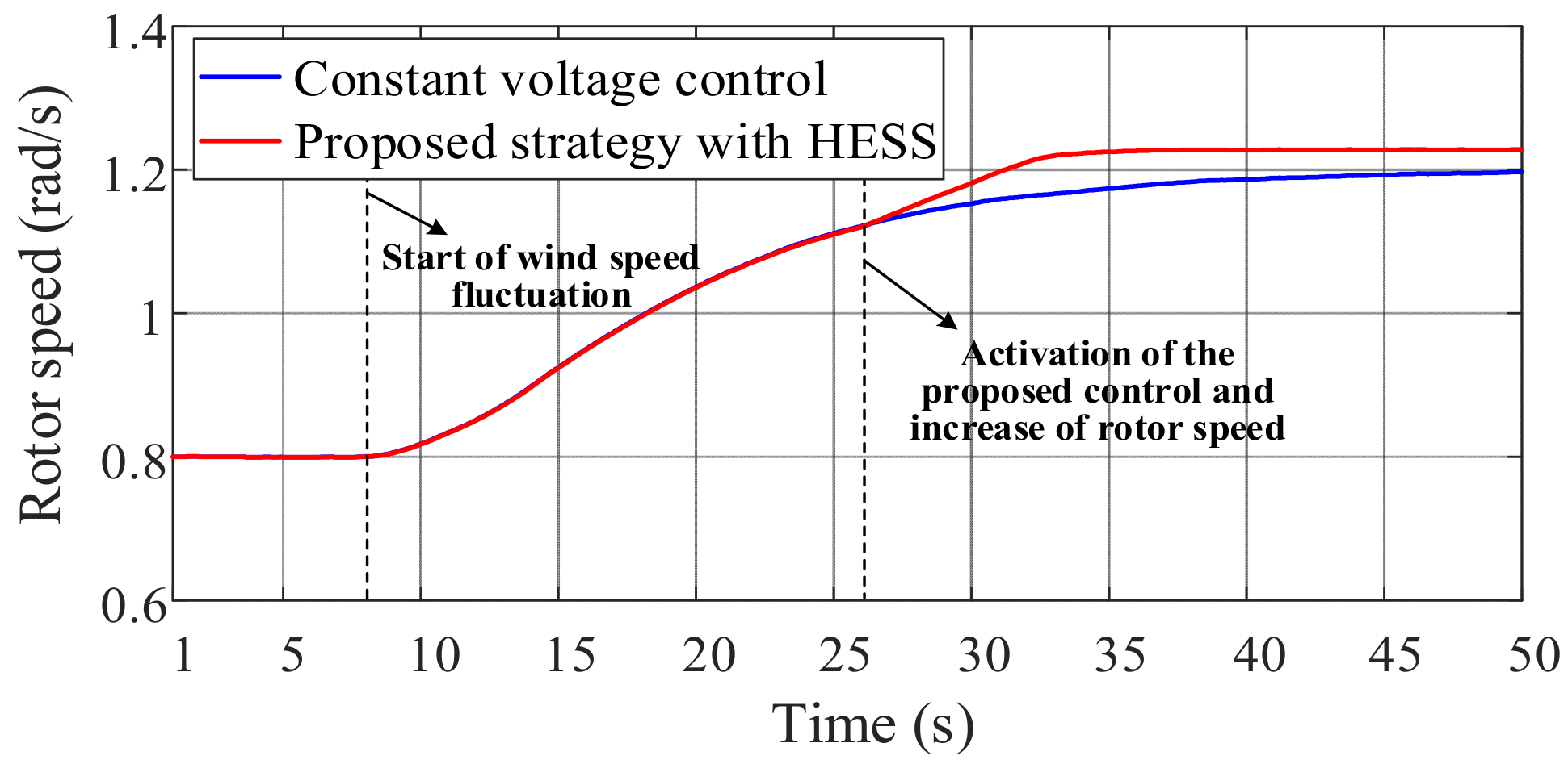
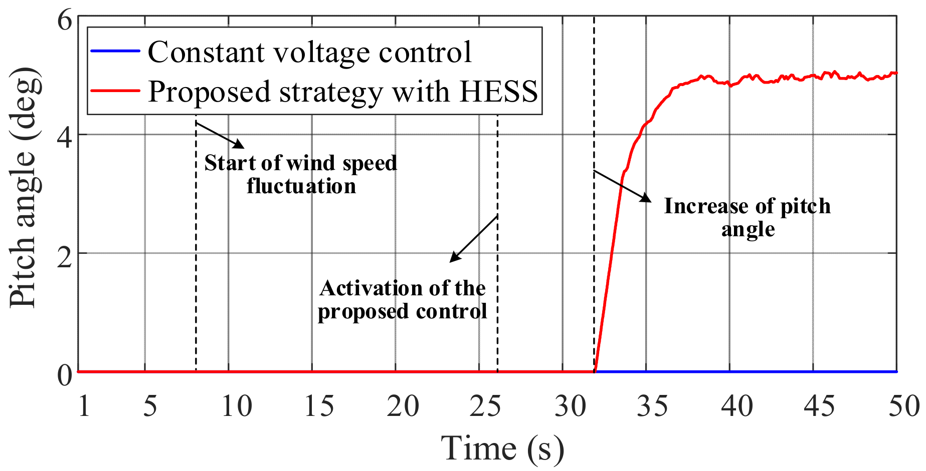
The proposed active and reactive power coordinate control strategy based on the LRP–RPCD operation curve reduces the active power output of the wind farm, which leads to incomplete utilization of the primary energy. HESS should be involved in the active voltage coordinate control of the DFIG, which could improve the availability of wind energy. In addition, HESS could deal with the PCC voltage fluctuation caused by the impulse load. The LIB in HESS is used to stabilize the voltage of the DC link and the fast response characteristics of the SC can cope with instantaneous power fluctuation caused by the impact load. To compensate the active power shortage, the HESS-based auxiliary control strategy is proposed in this paper. The purpose of the auxiliary control strategy is to adjust the working state of energy storage elements automatically according to the instructions and to realize the active voltage coordinate control of the DFIG based on the system operation parameters, so as to make full use of wind power resources. The energy losses for the LIB and the SC should be considered. Since this paper focuses on the control link, the discharge stage of HESS is mainly shown.
When ωωx, the energy flow in HESS is managed by the proposed auxiliary control strategy. The HESS-based auxiliary control strategy sets the critical operating point X as a dynamic reference point to define the initial state and establishes the criterion based on ωx and ωcr. The proposed control strategy of HESS is described in Figure 9.
The active power command PHESS of the HESS connected to the DFIG is calculated based on the real-time power. By comparing the relationship between ω, ωx, and ωcr, the piecewise function of PHESS can be expressed as:
P HESS = { K o p t ω 3 P g + P l o ω x < ω < ω c r ( P N K o p t ω 3 ) ω max ω c r ( ω ω max ) + P N P g + P l o ω ω c r
where Plo is the impact load. The HESS-based auxiliary control strategy allocates instructions according to the output power characteristics of energy storage elements, which can effectively realize energy control. The high-pass filter is used to filter the power instruction of HESS, and the high-frequency component is used as the active power command PSC for the SC. While the remaining part of the command PHESS after high pass filtering is used as the active power command PLIB of LIB energy storage. If the output active power of the energy storage element is greater than zero, it means discharging. Otherwise, it means charging. The relations of the HESS power distribution are shown as follows:
P SC ( D ) = D T f 1 + D T f P HESS ( D )
P LIB ( D ) = 1 1 + D T f P HESS ( D )
where D is a differential operator. The variable Tf is the filtering time constant, which is determined according to the frequency of power fluctuation that needs to be suppressed by the SC.
The HESS-based auxiliary control strategy takes the state of charge (SOC) as the judgment basis to assist in the realization of the active voltage coordinate control. In order to protect the energy storage equipment, the SOC limitation of the LIB and the SC should be considered by the HESS-based auxiliary control strategy, that is, the components will not be charged or discharged when the power limit is reached. By real-time monitoring the SOC of the LIB and the SC, the energy management strategy could ensure that components can respond to the power demand at any time, and avoid overcharge and over-discharge. The proposed HESS-based auxiliary control strategy could be represented in Table 1.
The addition of HESS enhances the disturbance resistance of DFIG. Due to the proposed HESS-based auxiliary control, the power shortage of the wind turbine could be compensated effectively. In addition, when the active voltage support function of DFIG is developed, the superposition of the voltage support function and the power compensation function could be realized. The DFIG with HESS is conducive to ensuring the stability of power in the wind farm. The HESS shall be installed on each DFIG to excavate the active voltage support capacity of the wind farm effectively.

5. Simulation

The simulation model is built in Matlab/Simulink. The system includes a wind farm and a grid shown in Figure 10. The wind farm consists of six DFIGs (1.5 MW) with the same parameters and control strategy. The total capacity of the wind farm is 9 MW. The wind farm is connected to the power grid through a 25 kV/120 kV transformer and a 50 km transmission line. After calculation, the value of Vcr is 12 m/s, while the rated wind speed of the DFIG is 14 m/s. The critical rotor speed ωcr is 1.2 p.u., when the synchronous speed is set as the reference value. The impact load is 1 MW. The acceptable range of PCC voltage is 0.97 p.u.–1.03 p.u. The capacity of the lithium-ion battery (LIB) in HESS is 255 kWh at USD 600 per kWh and the rated power is 85 kW. The capacity of the supercapacitor (SC) in HESS is 22 kWh at USD 3600 per kWh and the rated power is 215 kW. The maximum voltage on the low voltage side of the DC-DC converter is 750 V [37]. The installation cost of a single HESS is about USD 232,200.
In order to verify the effectiveness of the proposed strategy, two operation scenarios are considered, i.e., the critical operation point X is located in the BC zone and the CD zone, respectively. At the same time, the constant voltage control and the active voltage coordinate control without HESS are used as comparative verifications.

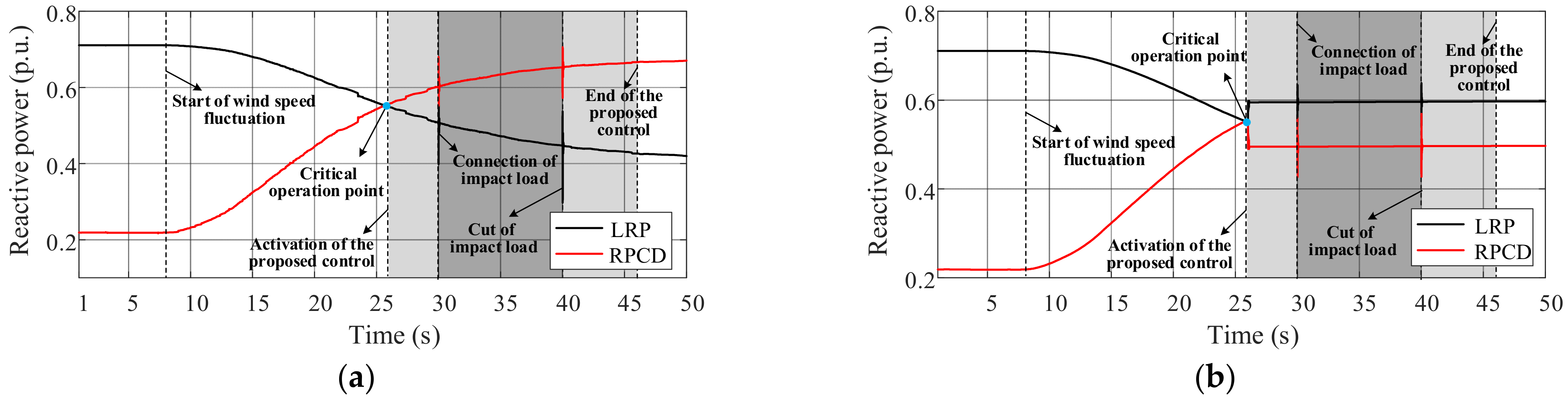
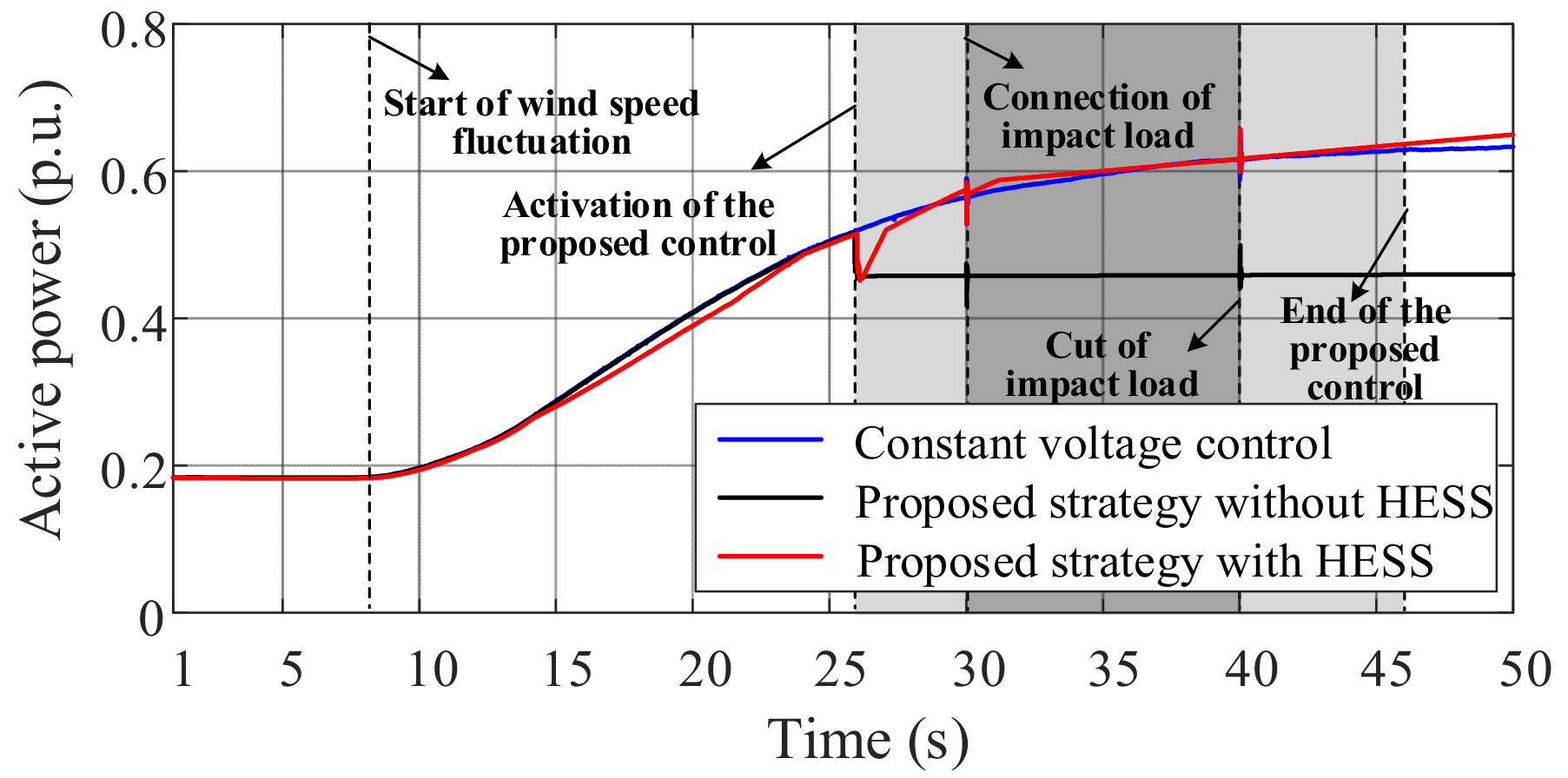
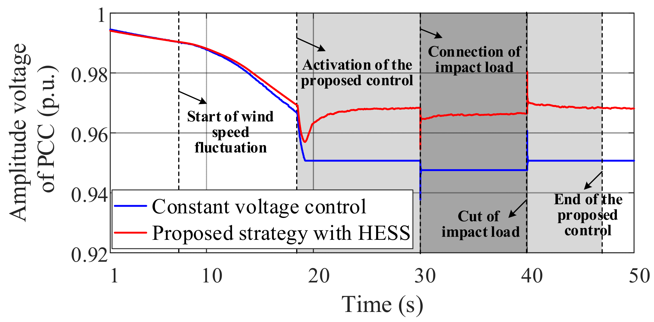
5.1. Case I: ωin ≤ ωx < ωcr

This case considers the point X located in the BC zone satisfies ωinωx < ωcr. The load in case I is 10 MW + j9Mvar. The impact load is 1 MW, which is connected at 30 s and cut off at 40 s. The wind speed increases from 8 m/s to 12 m/s within 6 s. The wind speed model is shown in Figure 11.
The increase in the wind speed leads to the decrease in the PCC voltage amplitude from 0.995 p.u. to 0.966 p.u. when the constant voltage control is only adopted by the DFIG. The impact load caused the voltage of PCC to drop further to 0.96 p.u. The voltage amplitude of PCC is shown in Figure 12.
In the scene of wind speed change, the reactive power decreased from 0.378 p.u. to 0.125 p.u., when the constant voltage control is only adopted by the DFIG, as shown via the blue line in Figure 13. Although more reactive power is output by DFIG after the impact load is connected, this cannot stabilize the voltage fluctuation of PCC. In the actual system, the rotor speed which is proportional to the wind speed changes slowly. At around 50 s, the rotor speed of the wind turbine increases to the critical speed under the variation of the wind speed shown via the blue line in Figure 14. The pitch angle remains at 0°, emerged via the blue line in Figure 15.
The real-time LRP–RPCD curve of the system under the constant voltage control is shown in Figure 16a, and the LRP curve decreases from 0.711 p.u. to 0.421 p.u., while the RPCD curve increases from 0.219 p.u. to 0.670 p.u. At the time of 25.753 s, the LRP of the wind farm is equal to the RPCD of the power grid and the corresponding rotor speed of the intersection is 1.118 rad/s satisfying ωinωx < ωcr.
The simulation results of the active voltage coordinate control and the constant voltage control are compared in this case. After 25.753 s, based on the LRP–RPCD operation curve, the active voltage coordinate control start-up by using the active ω-β coordinate control strategy and the active β control strategy. Under this condition, the voltage amplitude of PCC is increased to 0.991 p.u. When the DFIG adopts active voltage coordinate control, the changing situation of the PCC voltage is shown by the red line in Figure 12. With the active voltage coordinate control, the reactive power increases to 0.331 p.u. under the change process as shown via the red line in Figure 13. The curve of the rotor speed and the pitch angle is shown by the red line in Figure 14 and Figure 15, respectively. The rotor speed increases from 0.8 p.u. to 1.228 p.u., while the pitch angle rises to about 5°. Based on considering 0.1 p.u. margin, the active voltage coordinate control makes the LRP curve of the wind farm increase significantly and essentially satisfies the RPCD of the grid, as shown in Figure 16b. The effective action of the active voltage coordinate control ensures the stability of the system.
The output active power of the wind farm is shown in Figure 17, which is used to verify the system response of HESS. When the constant voltage control is adopted only, the output active power of the wind farm increases from 0.184 p.u. to 0.634 p.u. under the wind speed variation condition, as shown via the blue line in Figure 17. While the output active power of the wind farm is reduced to 0.459 p.u., when the active voltage coordinate control without HESS is used by the DFIG, shown by the black line in Figure 17. The output active power reduction in the wind farm caused by the active voltage coordinate control leads to the waste of primary energy.
To improve the utilization rate of the wind energy and ensure the power flow stability of the grid, HESS is used to maintain the output active power of the wind farm constant. Because of the HESS, the wind energy could be fully utilized, that is, the output active power of the DFIG with active voltage coordinate control is basically consistent as that with constant voltage control, shown by the red line in Figure 17. The output power of the LIB and the SC is shown in Figure 18, and the power command curve and the real-time power output curve are shown in Figure 19. The HESS-based auxiliary control strategy is applied in order to ensure a sharing of the energy flow between different elements, and the high pass filter is used to form the power demand of the LIB and the SC, respectively. It can be seen that the application of HESS effectively improves the utilization rate of primary energy, and the fast response characteristics of HESS can effectively suppress the harmful effects caused by the impact load.

5.2. Case II: ωx = ωcr

The load in case II absorbs 11.25 Mvar reactive power. The impact load is 1 MW, which is connected at 30 s and cut off at 40 s. The wind speed increases from 10 m/s to 14 m/s within 6 s. The wind speed curve is shown in Figure 20.
Because of the wind speed variations, a large number of reactive power shortages occur in the system, resulting in the voltage amplitude of PCC dropping from 0.995 p.u. to 0.951 p.u. when the constant voltage control is only adopted by the DFIG, shown via the blue line in Figure 21.
The output reactive power is shown by the blue line Figure 22 is decreases from 0.373 p.u. to 0.027 p.u. under the constant voltage control strategy. As the DFIG works in the CD zone, the variable ω is controlled at about 1.2 p.u. and the pitch angle is around 0.8°. The simulation results of rotor speed and pitch angle are indicated by the blue line in Figure 23 and Figure 24, respectively.
Sufficient active power output is accompanied by the deficiency of the LRP, which makes the wind farm lack the ability to support the PCC voltage. The real-time LRP curve of the wind farm and the RPCD curve of the grid are shown in Figure 25a. At 18.628 s, the LRP curve intersects the RPCD curve. The intersection point indicates that the LRP of the wind farm can meet the requirements of PCC voltage regulation, and the variable ω is 1.2 rad/s satisfying ωx = ωcr.
Obviously, it is difficult to maintain the voltage stability of PCC only by constant voltage control. At 18.628 s, the active voltage coordinate control comes into play to ensure the reactive power output margin of the wind farm. The voltage amplitude of PCC increases to nearly 0.97 p.u., as shown by the black line in Figure 21. During this process, the reactive power is increased, shown via the red line in Figure 22. By increasing pitch angle, the active β control strategy reduces the active power, shown via the black line in Figure 24. As shown by Figure 25b, the LRP of the wind farm is greater than the RPCD, when ω ≥ 1.2 rad/s. The LRP of the wind farm increases to 0.512 p.u., while the RPCD of the system is decreased to 0.394 p.u., and the margin of 0.1 p.u. is considered. The proposed control strategy ensures the reactive power support capacity of the wind farm under the condition of PCC voltage fluctuation.
The output active power of the wind farm is shown in Figure 26. When the constant voltage control is adopted only, the Pw of the wind farm increases from 0.196 p.u. to 0.878 p.u. under the wind speed variations, shown via the blue line in Figure 26. While the active power output by the wind farm is reduced when the active voltage coordinate control without HESS is used by the DFIG, shown by the black line in Figure 26.
To improve the utilization rate of the wind energy and ensure the power flow stability of the grid, HESS is used to maintain the output active power of the wind farm constant. The active power output by the wind farm under the action of the HESS is shown by the red line in Figure 26. The active power curve obtained by the proposed strategy with HESS is smoother than that obtained by the proposed strategy without HESS.
With the start of active voltage coordinate control, HESS realizes power control based on the auxiliary control strategy. The output power of the LIB and SC are shown in Figure 27. The power command and the real-time power of the HESS are indicated in Figure 28.
Figure 27 and Figure 28 show that the power command of HESS can be calculated accurately with the HESS-based auxiliary control strategy, and LIB and SC can output active power according to the command value. Under the action of HESS, the target of compensating for the power shortage of DFIG can be realized. As an auxiliary device, HESS has a positive effect on the realization of active voltage coordinate control strategy.
The above simulation results show that the proposed active voltage coordinate control strategy with HESS could combine the control characteristics of DFIG with the power compensation characteristics of HESS. The development of active voltage support capability of the wind farm provides an effective way to solve the resource shortage of fast reactive power regulation in the new power system.

6. Conclusions

In this paper, the interaction between the LRP of the wind farm and the RPCD of the grid is discussed in detail. On this basis, an active voltage coordinate control with HESS of DFIG-based wind farm is proposed to reduce the negative impact of the excessive wind speed variation and the load impact on the voltage stability of the connected system.
The results show that the proposed strategy can expand the reactive power capacity of DFIG and effectively excavate the active voltage support capacity of the wind farm. With the condition of considering the DFIG operation states, the influence of wind speed variation on the PCC voltage can be significantly suppressed by using the active and reactive power coordinate control strategy with active ω-β coordinate control and active β control. The HESS-based auxiliary control strategy can compensate the output active power of the wind farm. The introduction of HESS ensures the power flow stability of the local power grid and the utilization rate of primary energy. The proposed control strategy provides technical support for the coordinated control of the source and the power grid in the new power system.
However, the proposed strategy may increase the complexity of the DFIG control. The introduction of HESS aggravates the loss of DFIG, for example, the switching losses in the DC/DC converters are increased as mentioned in [38]. In addition, the proposed strategy may increase the construction cost and the maintenance cost of the wind farm. The area required by the construction of the wind farm has also been expanded accordingly.

Author Contributions

Conceptualization, Y.S., Y.W., Q.Z., J.L. and Z.Z.; methodology, Y.S., S.C. and Y.L.; software, Y.S., S.C. and Y.L.; validation, Y.S., S.C. and Y.L.; formal analysis, Y.S. and Y.L.; investigation, Y.S.; resources, Y.S.; data curation, Y.S.; writing—original draft preparation, Y.S.; writing—review and editing, Y.S.; visualization, Y.S.; supervision, J.L. and Z.Z.; project administration, Y.W. and Q.Z.; funding acquisition, Y.W. All authors have read and agreed to the published version of the manuscript.

Funding

This research was funded by the Science and Technology Project of State Grid Corporation of China: Key Control Technologies of Wind Power Transient Active Support, grant number 4000-202055048A-0-0-00.

Data Availability Statement

Data is contained within the article.

Conflicts of Interest

The authors declare no conflict of interest.

References

  1. Liserre, M.; Cárdenas, R.; Molinas, M.; Rodriguez, J. Overview of Multi-MW Wind Turbines and Wind Parks. IEEE Trans. Ind. Electron. 2011, 58, 1081–1095. [Google Scholar] [CrossRef]
  2. Liu, J.-H.; Cheng, J.-S. Online Voltage Security Enhancement Using Voltage Sensitivity-Based Coherent Reactive Power Control in Multi-Area Wind Power Generation Systems. IEEE Trans. Power Syst. 2021, 36, 2729–2732. [Google Scholar] [CrossRef]
  3. Llrab, C.; Oacv, B.; Ercd, C.; Jmg, D.; Ajsf, C. Generalized Predictive Control applied to the DFIG power control using state-space model and voltage constraints. Electr. Power Syst. Res. 2020, 182, 106227. [Google Scholar]
  4. Tian, X.; Wang, W.; Li, X.; Chi, Y.; Li, Y.; Tang, H. Fault ride through strategy of DFIG using rotor voltage direct compensation control under voltage phase angle jump. CSEE J. Power Energy Syst. 2019, 5, 515–523. [Google Scholar] [CrossRef]
  5. Mu, G.; Wang, J.; Yan, G. The mechanism of DFIGs grouping tripped off from power grid. CSEE J. Power Energy Syst. 2018, 4, 103–111. [Google Scholar] [CrossRef]
  6. Suppioni, V.P.; Grilo, A.P.; Teixeira, J.C. Control methodology for compensation of grid voltage unbalance using a series-converter scheme for the DFIG. Electr. Power Syst. Res. 2016, 133, 198–208. [Google Scholar] [CrossRef]
  7. Liu, Y.; Lin, Z.; Li, M.; Wu, Q.H. On the state-dependent switched energy functions of DFIG-based wind power generation systems. CSEE J. Power Energy Syst. 2020, 6, 318–328. [Google Scholar] [CrossRef]
  8. Guo, Q.; Sun, H.; Wang, B.; Zhang, B.; Wu, W.; Tang, L. Hierarchical automatic voltage control for integration of large-scale wind power: Design and implementation. Electr. Power Syst. Res. 2015, 120, 234–241. [Google Scholar] [CrossRef]
  9. Berndt, H.; Hermann, M.; Kreye, H.D.; Reinisch, R.; Scherer, U.; Vanzetta, J. Network and System Rules of the German Transmission System Operators; Verband der Netzbetreiber: Berlin, Germany, 2007. [Google Scholar]
  10. Alberta Electric Power System Operator. Wind Power Facility Technical Requirements; Alberta Electric Power System Operator: Calgary, AB, Canada, 2004. [Google Scholar]
  11. ELTRA Transmission System Planning. Specifications for Connecting Wind Farms to the Transmission Network. 2nd ed. Standard ID: ELT1999–411a. 26 April 2000. Available online: https://www.doc88.com/p-7436285682320.html?r=1 (accessed on 6 December 2021).
  12. China Electric Power Research Institute. Technical Rule for Connecting Wind Farm to Power System. Standard ID: GB/T 19963–2011. 2011. Available online: https://www.chinesestandard.net/PDF/English.aspx/GBT19963-2011 (accessed on 6 December 2021).
  13. Kafshgari, N.A.; Ramezani, N.; Nouri, H. Effects of high frequency modeling & grounding system parameters on transient recovery voltage across vacuum circuit breakers for capacitor switching in wind power plants. Int. J. Electr. Power Energy Syst. 2019, 104, 159–168. [Google Scholar]
  14. Abulanwar, S.; Hu, W.; Chen, Z.; Iov, F. Adaptive voltage control strategy for variable-speed wind turbine connected to a weak network. IET Renew. Power Gener. 2016, 10, 238–249. [Google Scholar] [CrossRef]
  15. Bian, X.Y.; Geng, Y.; Lo, K.L.; Fu, Y.; Zhou, Q.B. Coordination of PSSs and SVC Damping Controller to Improve Probabilistic Small-Signal Stability of Power System With Wind Farm Integration. IEEE Trans. Power Syst. 2015, 31, 2371–2382. [Google Scholar] [CrossRef] [Green Version]
  16. Global Wind Energy Council. Global Wind Report 2019; Global Wind Energy Council: Brussels, Belgium, 2020; Available online: https://gwec.net/global-wind-report-2019/ (accessed on 7 December 2021).
  17. Ghosh, S.; Isbeih, Y.J.; Bhattarai, R.; El Moursi, M.S.; El-Saadany, E.F.; Kamalasadan, S. A Dynamic Coordination Control Architecture for Reactive Power Capability Enhancement of the DFIG-Based Wind Power Generation. IEEE Trans. Power Syst. 2020, 35, 3051–3064. [Google Scholar] [CrossRef]
  18. Dong, Z.; Li, Z.; Du, L.; Liu, Y.; Ding, Z. Coordination Strategy of Large-Scale DFIG-Based Wind Farm for Voltage Support With High Converter Capacity Utilization. IEEE Trans. Sustain. Energy 2020, 12, 1416–1425. [Google Scholar] [CrossRef]
  19. Tian, J.; Zhou, D.; Su, C.; Chen, Z.; Blaabjerg, F. Reactive Power Dispatch Method in Wind Farms to Improve the Lifetime of Power Converter Considering Wake Effect. IEEE Trans. Sustain. Energy 2016, 8, 477–487. [Google Scholar] [CrossRef] [Green Version]
  20. Li, Y.; Xu, Z.; Zhang, J.; Meng, K. Variable Droop Voltage Control for Wind Farm. IEEE Trans. Sustain. Energy 2017, 9, 491–493. [Google Scholar] [CrossRef]
  21. Zhao, H.; Wu, Q.; Guo, Q.; Sun, H.; Huang, S.; Xue, Y. Coordinated Voltage Control of a Wind Farm Based on Model Predictive Control. IEEE Trans. Sustain. Energy 2016, 7, 1440–1451. [Google Scholar] [CrossRef] [Green Version]
  22. Zhao, H.; Wu, Q.; Wang, J.; Liu, Z.; Shahidehpour, M.; Xue, Y. Combined Active and Reactive Power Control of Wind Farms Based on Model Predictive Control. IEEE Trans. Energy Convers. 2017, 32, 1177–1187. [Google Scholar] [CrossRef] [Green Version]
  23. Li, J.; Wang, S.; Ye, L.; Fang, J. A coordinated dispatch method with pumped-storage and battery-storage for compensating the variation of wind power. Prot. Control. Mod. Power Syst. 2018, 3, 2. [Google Scholar] [CrossRef] [Green Version]
  24. Londero, R.R.; Affonso, C.M.; Vieira, J.P.A. Long-Term Voltage Stability Analysis of Variable Speed Wind Generators. IEEE Trans. Power Syst. 2014, 30, 439–447. [Google Scholar] [CrossRef]
  25. Ouyang, J.; Tang, T.; Yao, J.; Li, M. Active Voltage Control for DFIG-based Wind Farm Integrated Power System by Coor-dinating Active and Reactive Powers under Wind Speed Variations. IEEE Trans. Energy Convers. 2019, 34, 1504–1511. [Google Scholar] [CrossRef]
  26. Gabash, A.; Li, P. Active-Reactive Optimal Power Flow in Distribution Networks With Embedded Generation and Battery Storage. IEEE Trans. Power Syst. 2012, 27, 2026–2035. [Google Scholar] [CrossRef]
  27. Gabash, A.; Li, P. On the control of main substations between transmission and distribution systems. In Proceedings of the 14th International Conference on Environment and Electrical Engineering (EEEIC), Krakow, Poland, 10–12 May 2014. [Google Scholar]
  28. Mohagheghi, E.; Alramlawi, M.; Gabash, A.; Blaabjerg, F.; Li, P. Real-Time Active-Reactive Optimal Power Flow with Flexible Operation of Battery Storage Systems. Energies 2020, 13, 1697. [Google Scholar] [CrossRef] [Green Version]
  29. Gabash, A.; Li, P. On Variable Reverse Power Flow-Part II: An Electricity Market Model Considering Wind Station Size and Location. Energies 2016, 9, 235. [Google Scholar] [CrossRef] [Green Version]
  30. Khazaei, J.; Nguyen, D.H. Distributed Consensus for Output Power Regulation of DFIGs with On-Site Energy Storage. IEEE Trans. Energy Convers. 2018, 34, 1043–1051. [Google Scholar] [CrossRef]
  31. de Carvalho, W.C.; Bataglioli, R.P.; Fernandes, R.A.; Coury, D.V. Fuzzy-based approach for power smoothing of a full-converter wind turbine generator using a supercapacitor energy storage. Electr. Power Syst. Res. 2020, 184, 106287. [Google Scholar] [CrossRef]
  32. Kadri, A.; Marzougui, H.; Aouiti, A.; Bacha, F. Energy management and control strategy for a DFIG wind turbine/fuel cell hybrid system with super capacitor storage system. Energy 2019, 192, 116518. [Google Scholar] [CrossRef]
  33. Baros, S.; MD, I. A Consensus Approach to Real-Time Distributed Control of Energy Storage Systems in Wind Farms. IEEE Trans. Smart Grid 2019, 10, 613–625. [Google Scholar] [CrossRef]
  34. Kim, J.; Muljadi, E.; Gevorgian, V.; Hoke, A.F. Dynamic Capabilities of an Energy Storage-Embedded DFIG System. IEEE Trans. Ind. Appl. 2019, 55, 4124–4134. [Google Scholar] [CrossRef]
  35. Prajapat, G.P.; Senroy, N.; Kar, I. Estimation based enhanced maximum energy extraction scheme for DFIG-wind turbine systems. Sustain. Energy Grids Networks 2020, 26, 100419. [Google Scholar] [CrossRef]
  36. Rahimi, M. Coordinated control of rotor and grid sides converters in DFIG based wind turbines for providing optimal reactive power support and voltage regulation. Sustain. Energy Technol. Assess. 2017, 20, 47–57. [Google Scholar] [CrossRef]
  37. Ju, C.; Wang, P.; Goel, L.; Xu, Y. A Two-layer Energy Management System for Microgrids with Hybrid Energy Storage con-sidering Degradation Costs. IEEE Trans. Smart Grid 2017, 9, 6047–6057. [Google Scholar] [CrossRef]
  38. Kawan, Y.K.; Gabash, A. Impact of Series Resonant Power Conditioning System Losses in Optimal Power Flow. In Proceedings of the 2018 IEEE International Conference on Environment and Electrical Engineering and 2018 IEEE Industrial and Commercial Power Systems Europe (EEEIC/I&CPS Europe), Palermo, Italy, 12–15 June 2018; pp. 1–6. [Google Scholar]
Figure 1. The overall structure system of the DFIG with HESS.
Electronics 10 03060 g001
Figure 2. The operation characteristics of DFIG based on Pg, v and ω.
Electronics 10 03060 g002
Figure 3. The power characteristics of energy generation from the DFIG-based wind farm. (a) The interaction between the LPR and the RPCD. (b) The active power characteristics of DFIG.
Electronics 10 03060 g003
Figure 4. The structure of the active voltage coordinate control strategy.
Electronics 10 03060 g004
Figure 5. The power variation characteristics of DFIG with the active ω-β coordinate control strategy based on the LRP–RPCD operation curve.
Electronics 10 03060 g005
Figure 6. The active ω-β coordinate control strategy and the control logic. (a) The active power control and the pitch angle control in the active ω-β coordinate control strategy. (b) The active ω-β coordinate control logic.
Electronics 10 03060 g006
Figure 7. The power variation characteristics of DFIG with the active β control strategy based on the LRP–RPCD operation curve.
Electronics 10 03060 g007
Figure 8. The active β coordinate control strategy and the control logic. (a) The pitch angle control in the active β control strategy. (b) The active β coordinate control logic.
Electronics 10 03060 g008
Figure 9. The schematic diagram of the proposed HESS-based auxiliary control strategy.
Electronics 10 03060 g009
Figure 10. The schematic diagram of simulation system.
Electronics 10 03060 g010
Figure 11. The fluctuating wind speed in case I.
Electronics 10 03060 g011
Figure 12. The voltage amplitude of PCC in case I.
Electronics 10 03060 g012
Figure 13. The output reactive power of the wind farm in case I.
Electronics 10 03060 g013
Figure 14. The rotor speed of the DFIG in case I.
Electronics 10 03060 g014
Figure 15. The pitch angle of the DFIG in case I.
Electronics 10 03060 g015
Figure 16. Real-time LRP and RPCD curves in case I. (a) Constant voltage control. (b) Active voltage coordinate control with HESS.
Electronics 10 03060 g016
Figure 17. The output active power of the wind farm in case I.
Electronics 10 03060 g017
Figure 18. The output power of LIB and SC. (a) Output power of LIB. (b) Output power of SC.
Electronics 10 03060 g018
Figure 19. The power command curve and the real-time power output curve of HESS in case I.
Electronics 10 03060 g019
Figure 20. The fluctuating wind speed in case II.
Electronics 10 03060 g020
Figure 21. The voltage amplitude of PCC in case II.
Electronics 10 03060 g021
Figure 22. The output reactive power of the DFIG in case II.
Electronics 10 03060 g022
Figure 23. The rotor speed of the DFIG in case II.
Electronics 10 03060 g023
Figure 24. The pitch angle of the DFIG in case II.
Electronics 10 03060 g024
Figure 25. Real-time LRP and RPCD curves in case II. (a) Constant voltage control. (b) Active voltage coordinate control with HESS.
Electronics 10 03060 g025
Figure 26. The output active power of the wind farm in case II.
Electronics 10 03060 g026
Figure 27. The output power of LIB and SC in case II. (a) Output power of LIB. (b) Output power of SC.
Electronics 10 03060 g027
Figure 28. The power command curve and the real-time power output curve of HESS in case II.
Electronics 10 03060 g028
Table 1. The HESS-based auxiliary control strategy.
ModeOperating ConditionsState
PHESSSOCLSOCSLIBSC
1>0 > SOC min L > SOC min S DischargeDischarge
2 > SOC min L < SOC min S DischargeOver discharge protection
3 < SOC min L > SOC min S Over discharge protectionDischarge
4 < SOC min L < SOC min S Over discharge protectionOver discharge protection
Publisher’s Note: MDPI stays neutral with regard to jurisdictional claims in published maps and institutional affiliations.

