
The Study of Bending and Twisting Input Modalities in Deformable Interfaces

Abstract
:1. Introduction
2. Materials Instruction
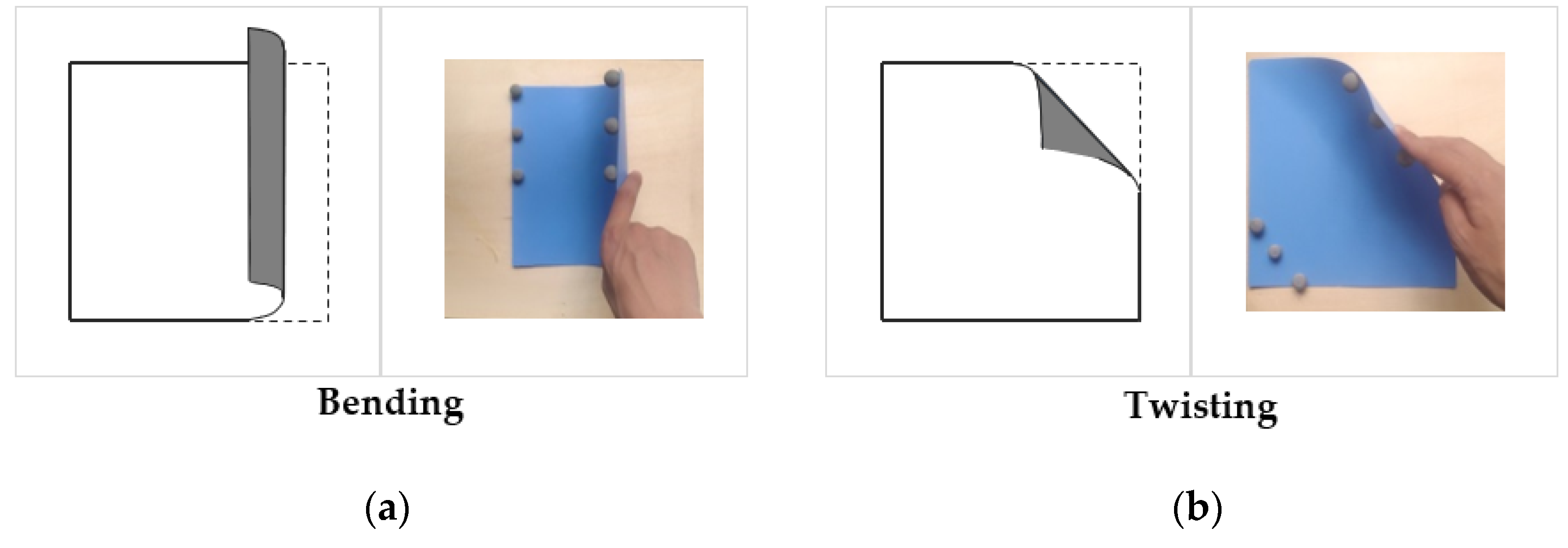
2.1. Input Modes
- The deformation gestures must be universal (that is, they can be realized on as many materials as possible), because different materials allow different forms of deformation; plastic sheets are the most similar type of flexible display material that is currently available [18];
- The deformation gestures must give the feeling of using real thing [19];
- The deformation gestures must have a high degree of consistency in orientation [10];
- The deformation gestures must have powerful powerful metaphors [19].
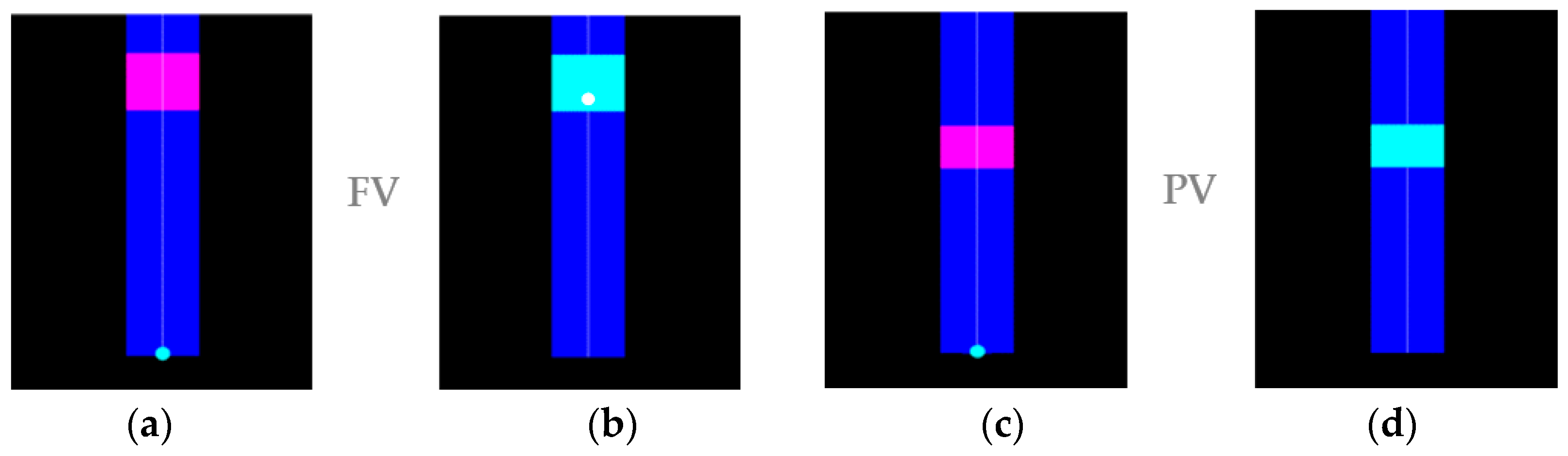
2.2. Visual Feedback
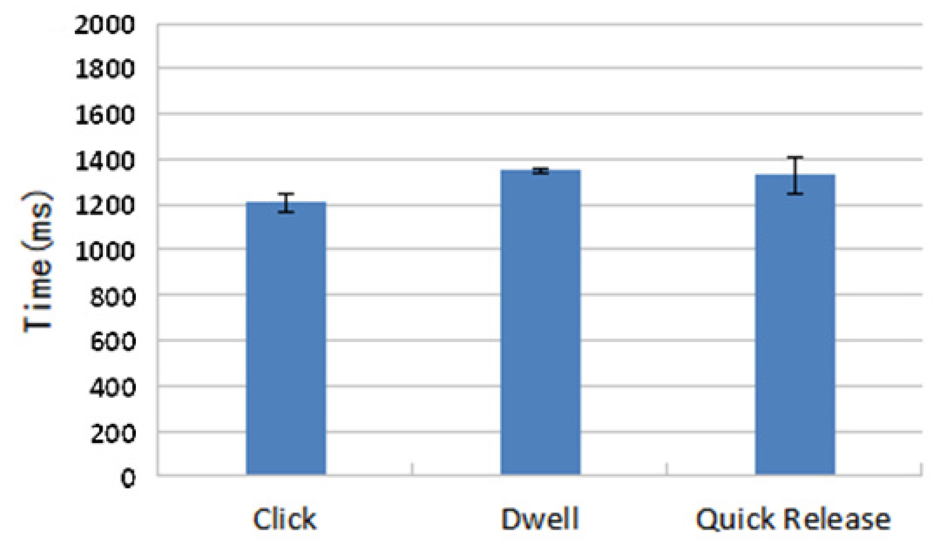
2.3. Selection Technologies
- Click: Move the cursor by bending or twisting the FlexSheet. When the cursor appears within the target rectangle, click the task button to complete the target selection;
- Dwell: Bending or twisting the FlexSheet to move the cursor until it appears within the target, then keep the cursor in the target for a specified period of time to complete the target selection (in our experiment, a delay of 0.7 seconds was used);
- Quick Release: Move the cursor by bending or twisting the FlexSheet. When the cursor appears in the target, quickly remove the FlexSheet from the deformed state.
3. Controlled Experiment
3.1. Participants
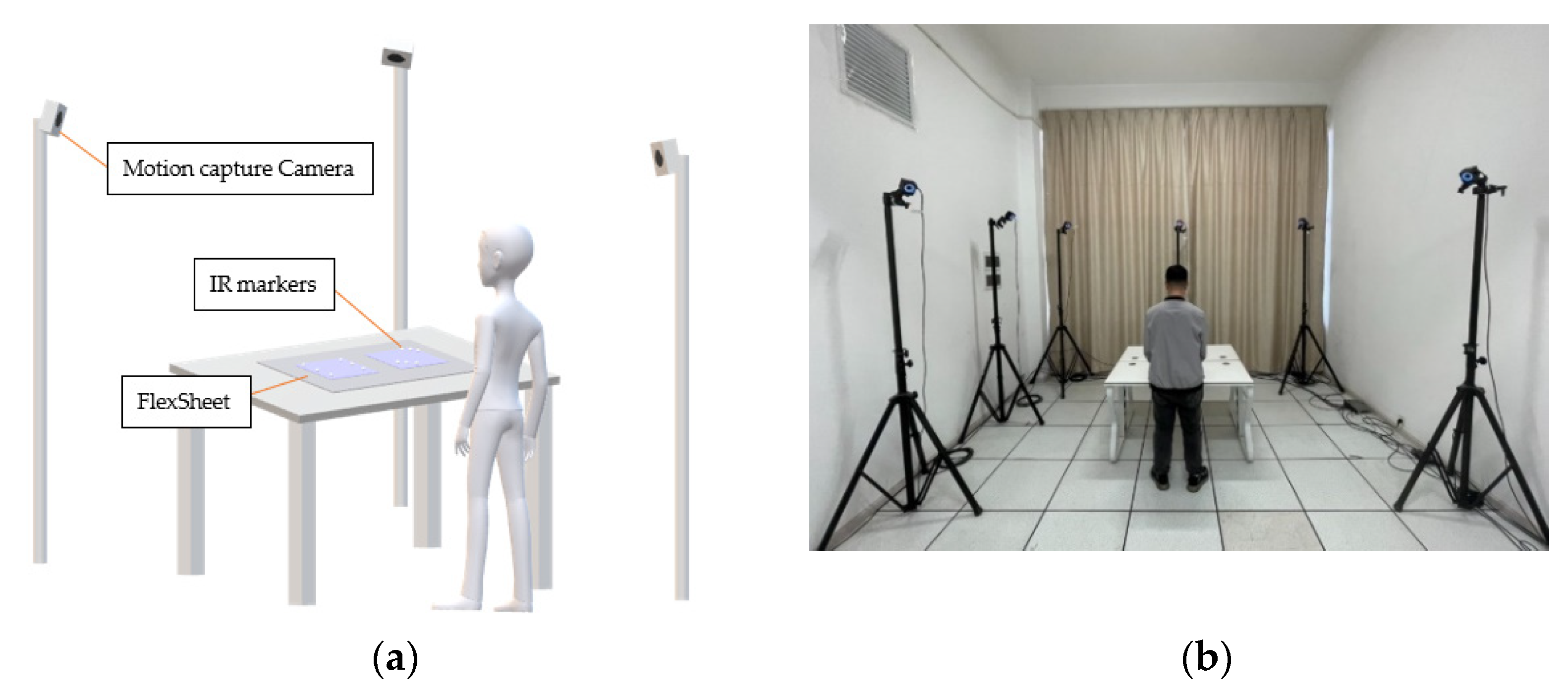
3.2. Apparatus and Environment
3.3. Task
3.4. Performance Measures
3.5. Procedure and Design
- Selection modes (Bending and Twisting);
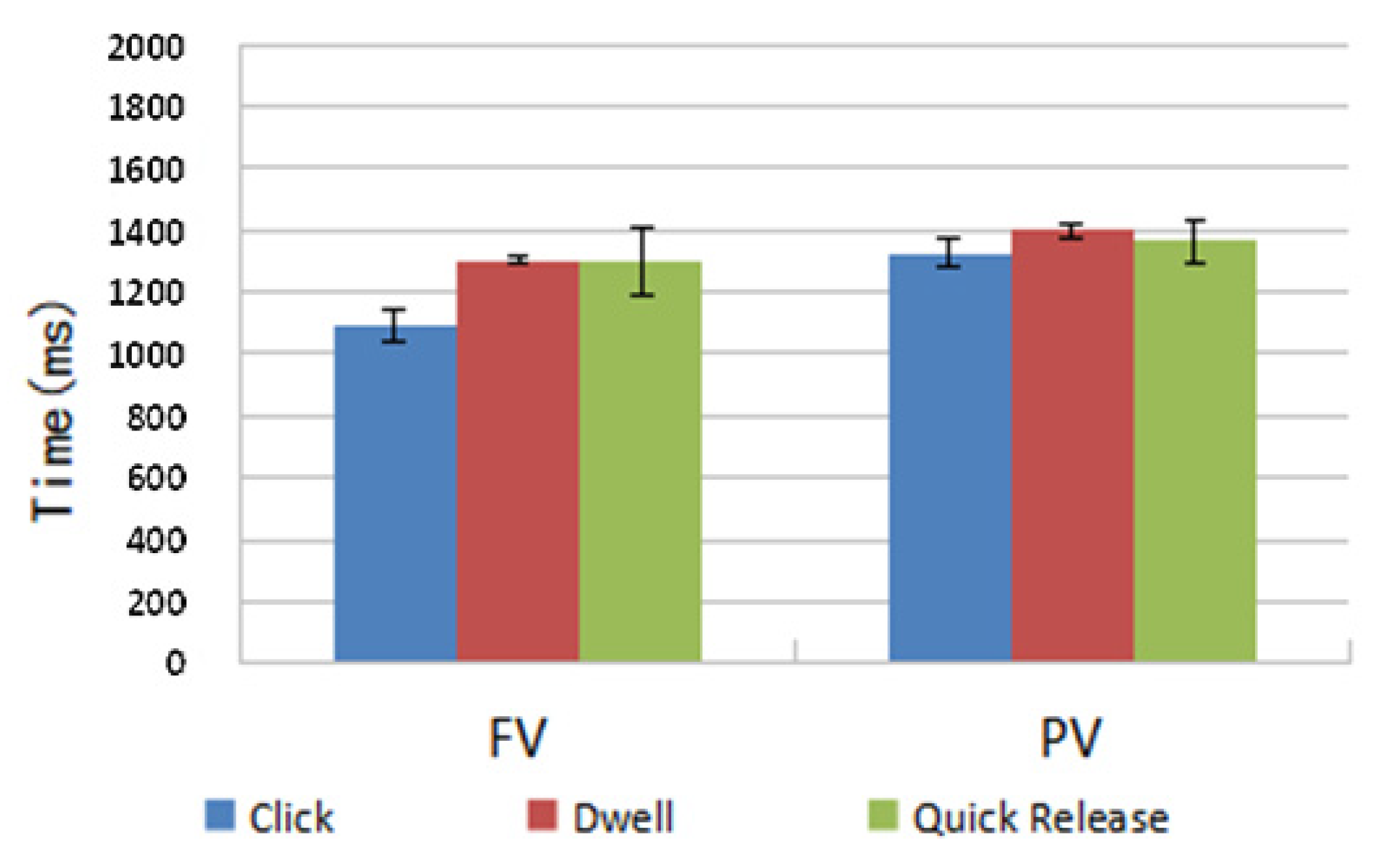
- Visual feedback conditions (FV and PV);
- Selection technologies (Click, Dwell and Quick Release);
- Target distance (D = 37, 72, 109, 144);
- Target width (W = 15, 18, 22.5, 30, 45);
- 12 Participants
- 3 Repetitions
4. Results
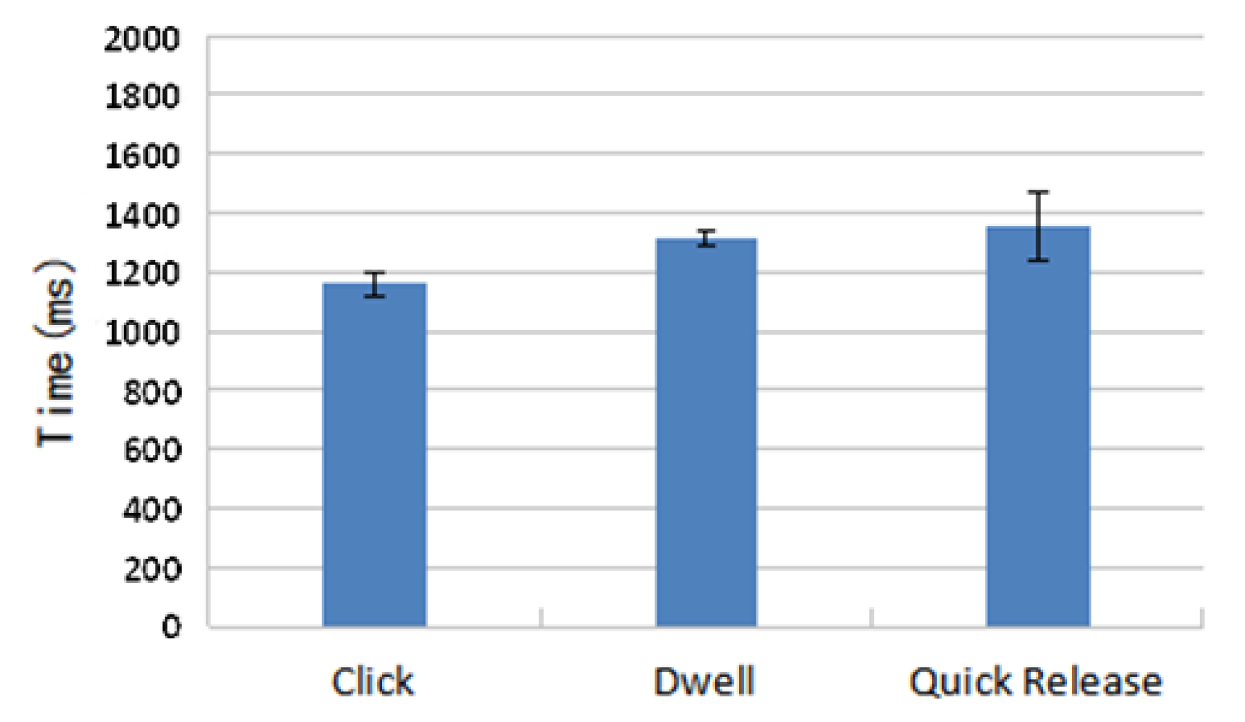
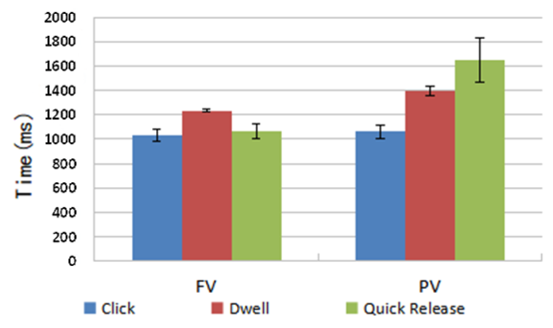
4.1. Time
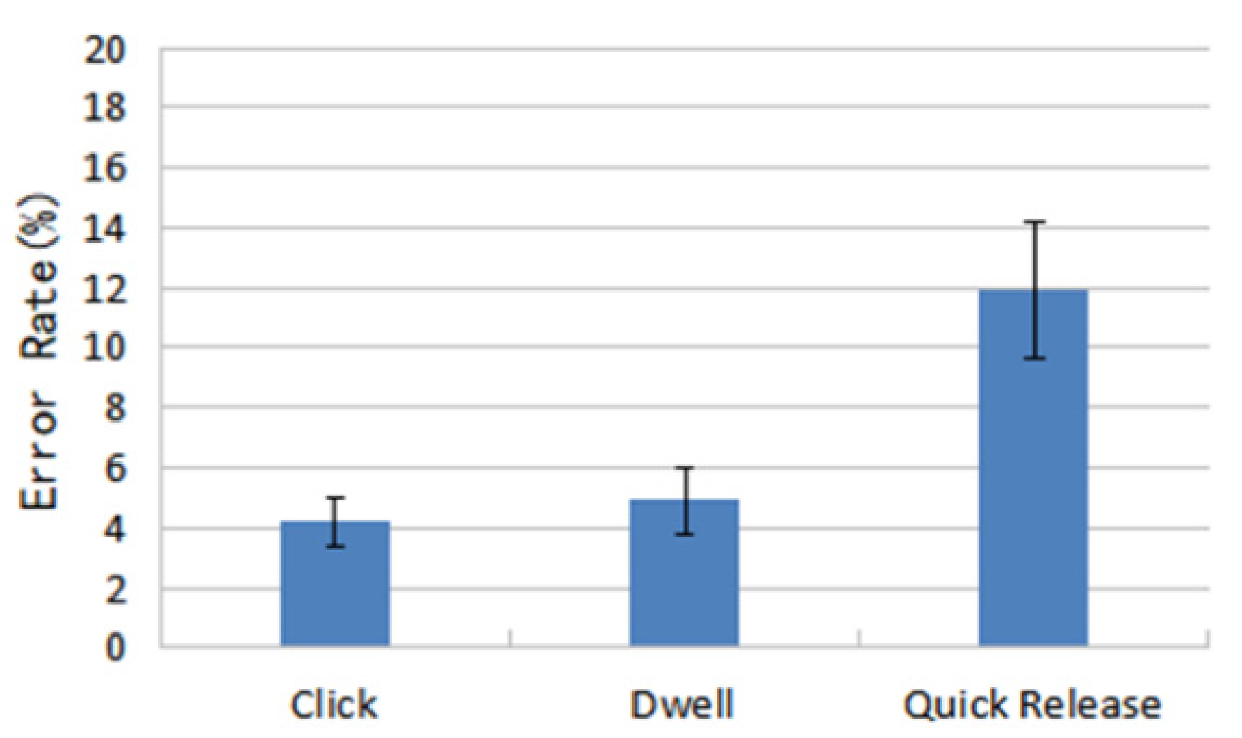
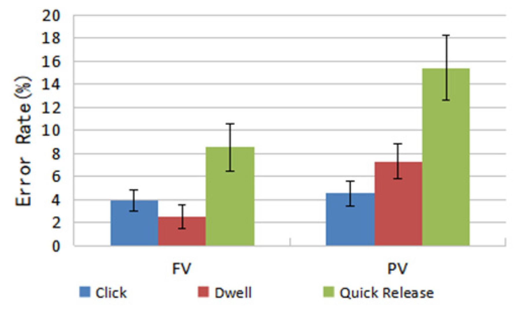
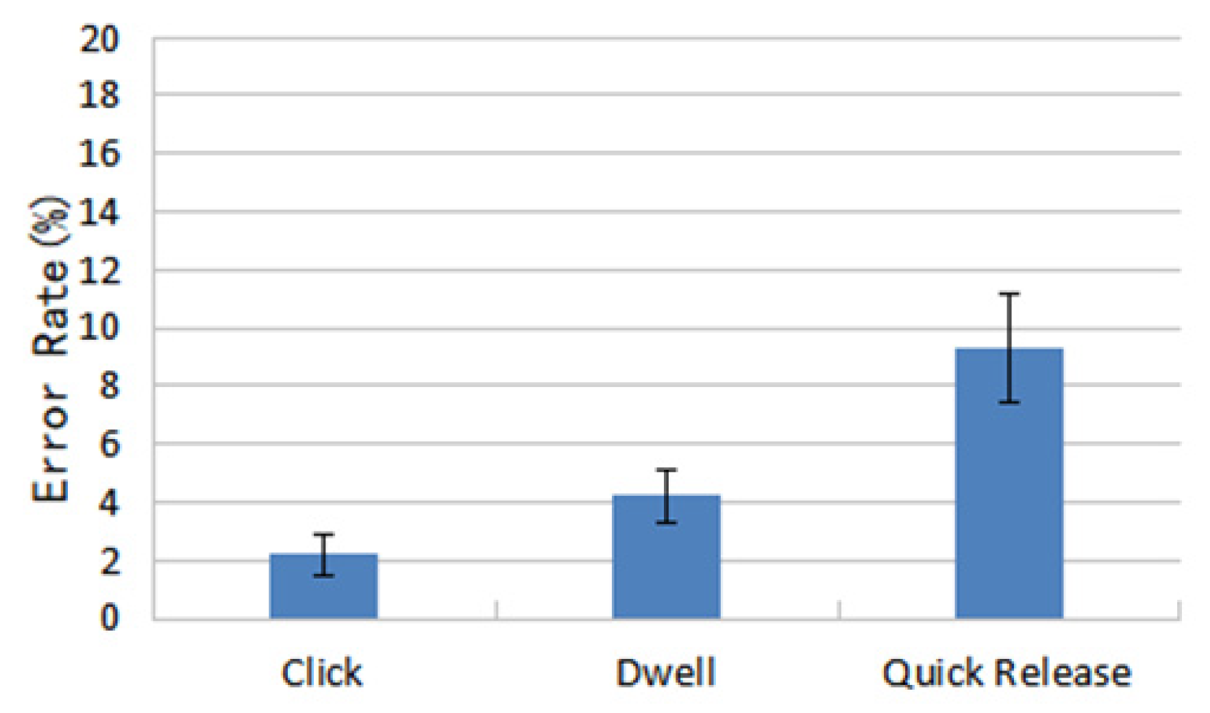
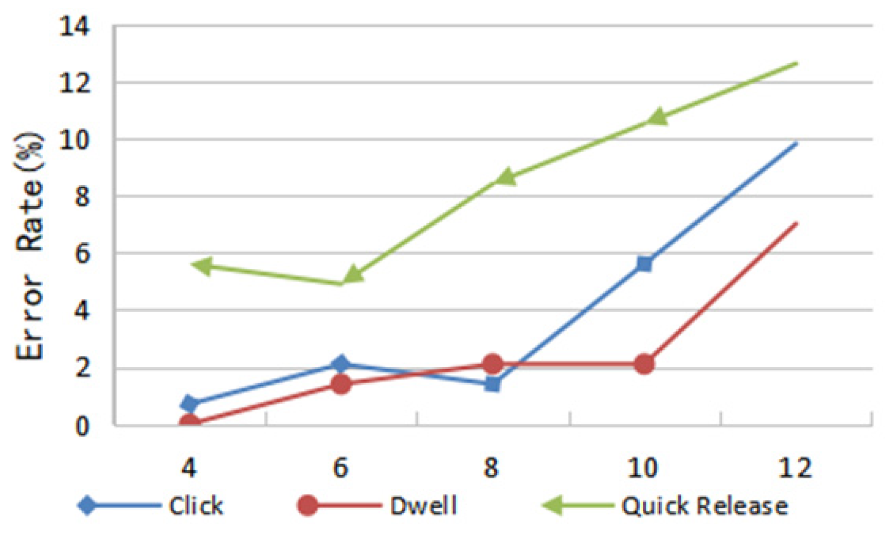
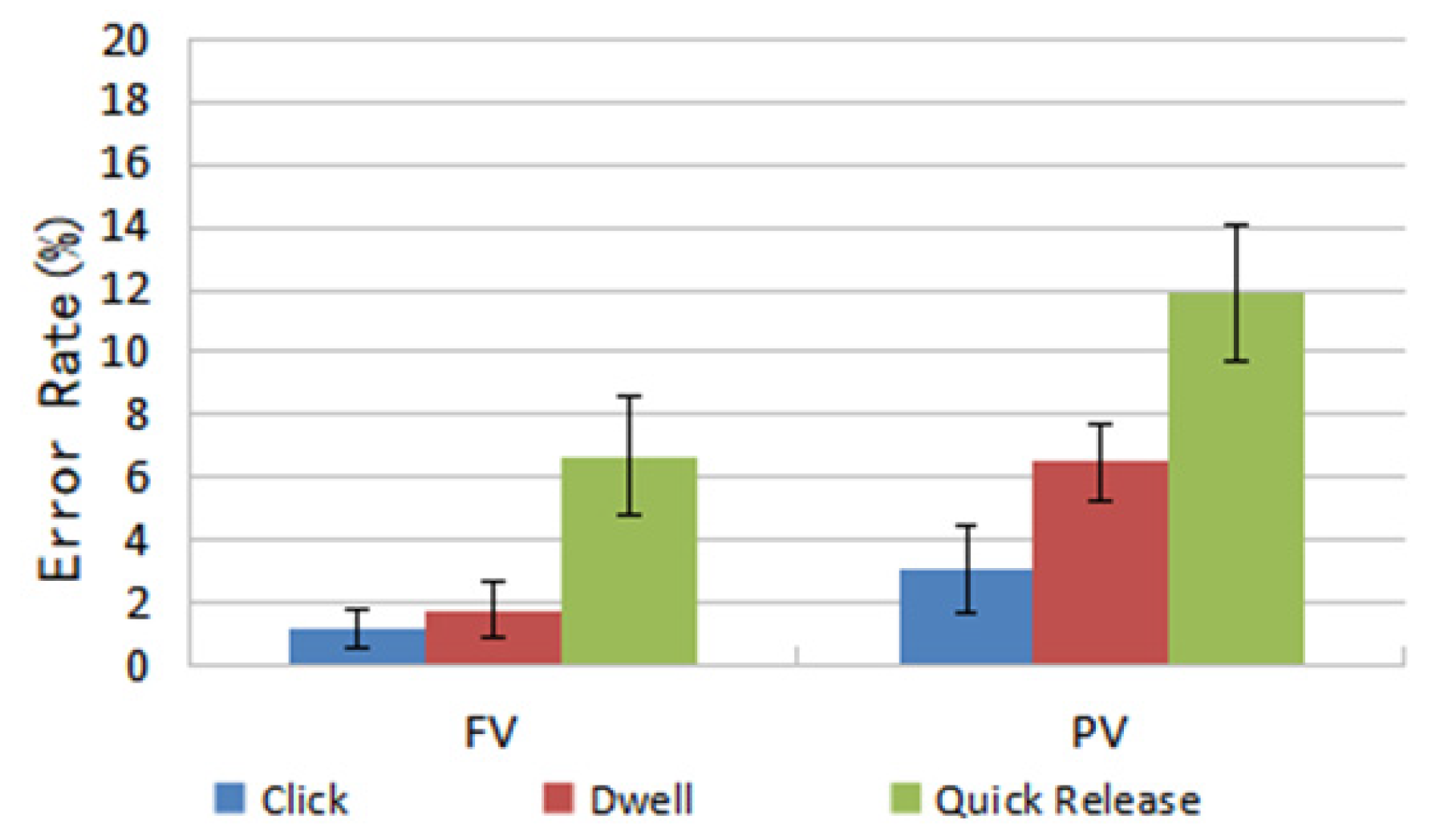
4.2. Accuracy
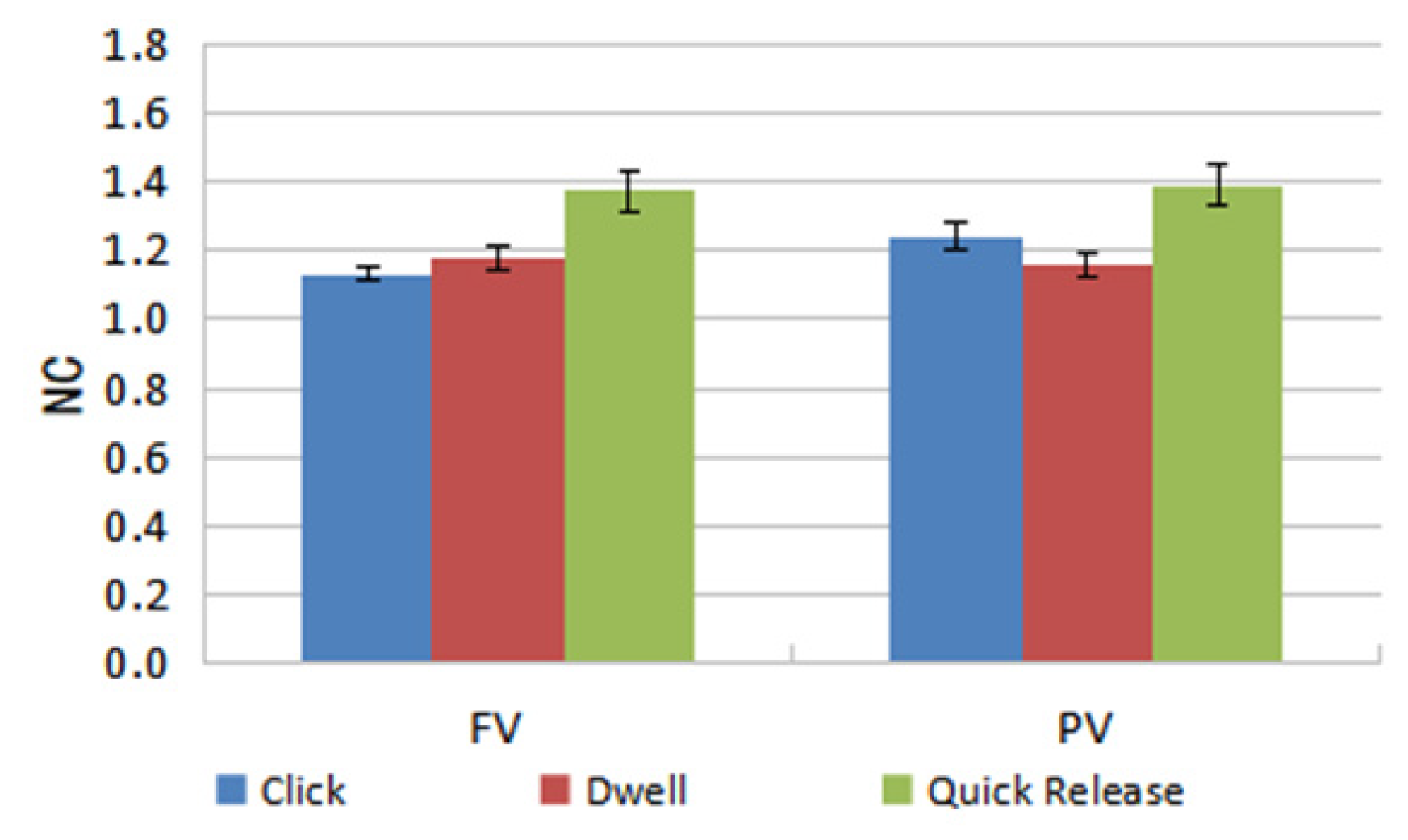
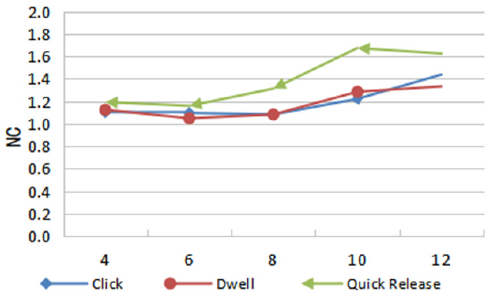
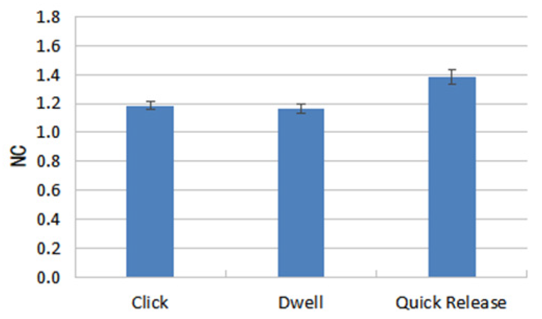
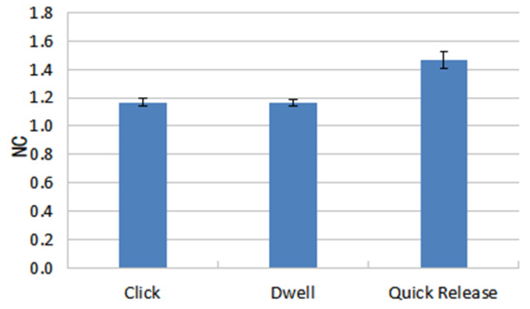
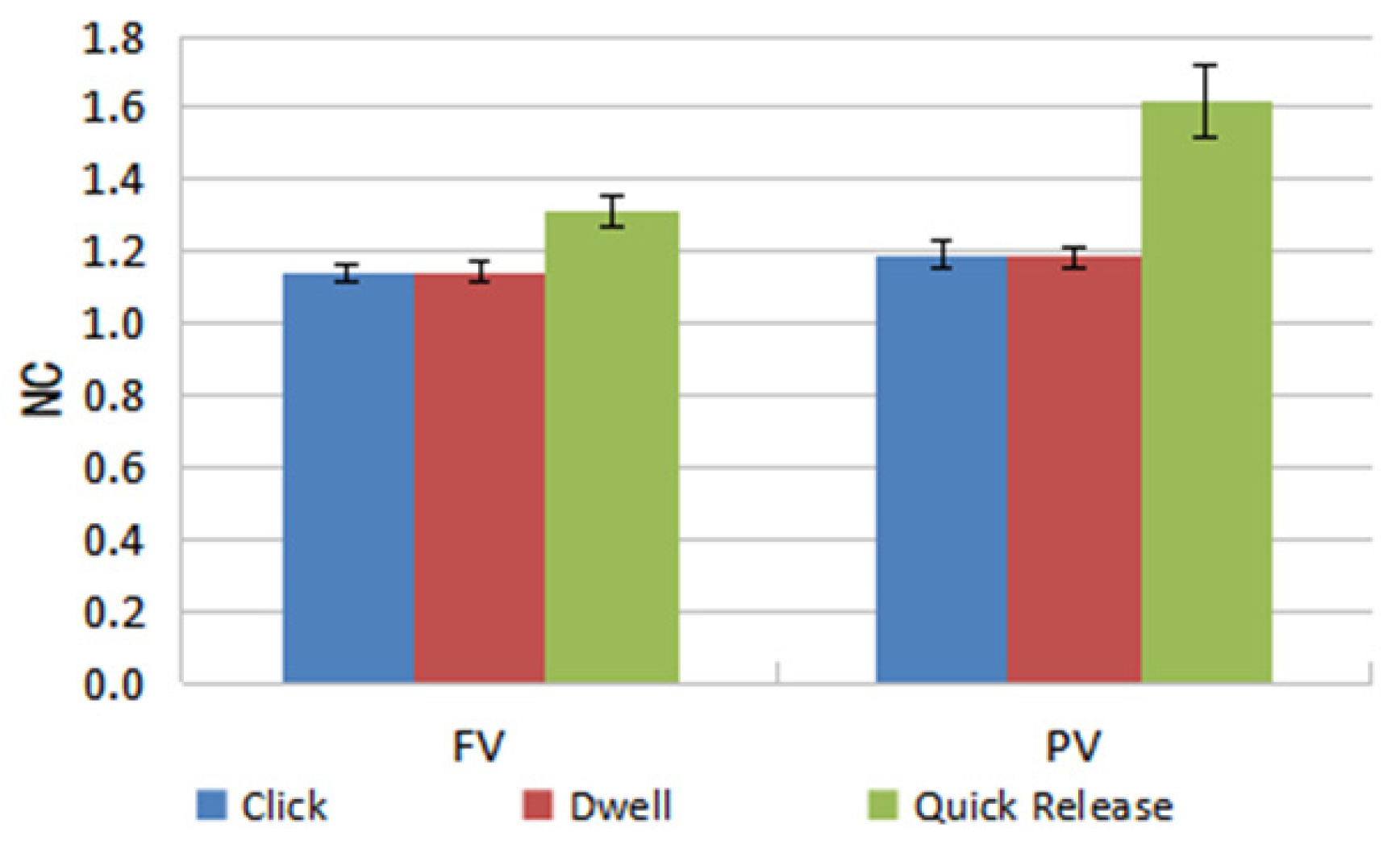
4.3. Indication of Control
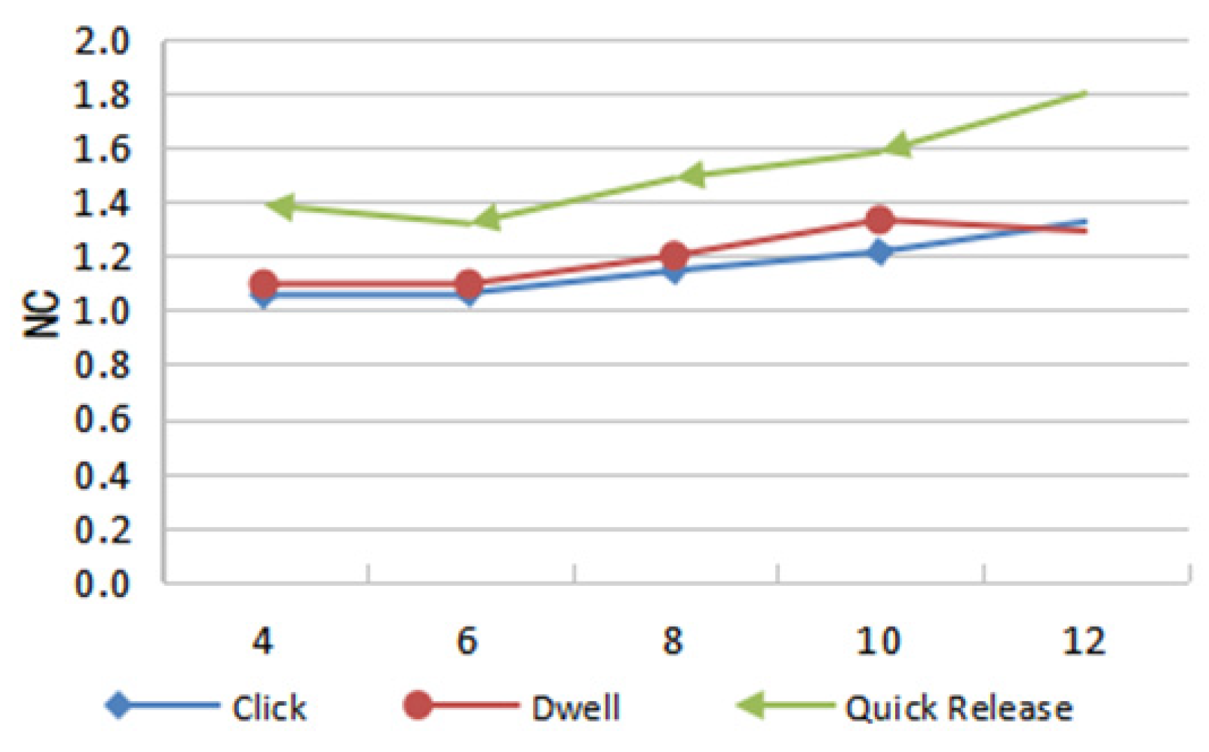
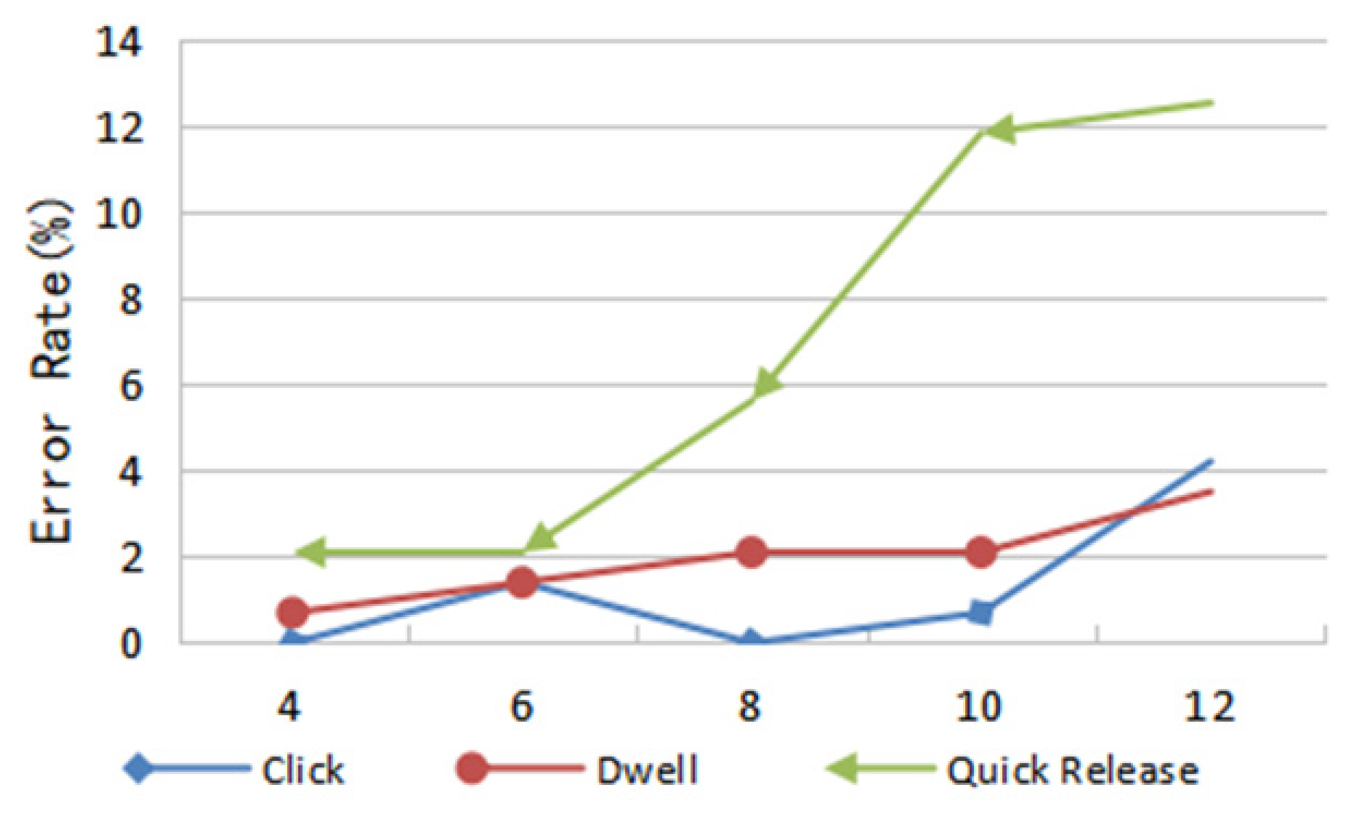
4.4. Optimum Number of Deformation Levels
5. Discussion and Conclusions
Author Contributions
Funding
Acknowledgments
Conflicts of Interest
References
- Inoue, Y.; Itoh, Y.; Onoye, T. TuVe: A flexible display with a tube. In SIGGRAPH Asia 2018 Emerging Technologies (SA’18); Association for Computing Machinery: New York, NY, USA, 2018; pp. 1–2. [Google Scholar]
- David, H.; Roel, V. Organic user interfaces: Designing computers in any way, shape, or form. ACM 2008, 51, 48–55. [Google Scholar]
- Mone, G. The future is flexible displays. Commun. ACM 2013, 56, 16–17. [Google Scholar] [CrossRef]
- Girouard, A.; Eady, A.K. Deformable User Interfaces: Using Flexible Electronics for Human mputer Interaction. In Proceedings of the International Flexible Electronics Technology Conference, Ottawa, ON, Canada, 7–9 August 2018. [Google Scholar] [CrossRef]
- Lahey, B.; Girouard, A.; Burleson, W.; Vertegaal, R. PaperPhone: Understanding the Use of Bend Gestures in Mobile Devices with Flexible Electronic Paper Displays. In Proceedings of the SIGCHI Conference on Human Factors in Computing Systems (CHI’11), New York, NY, USA, 5–10 May 2011; pp. 1303–1312. [Google Scholar] [CrossRef]
- Gomes, A.; Priyadarshana, L.; Carrascal, J.P.; Vertegaal, R. WhammyPhone: Exploring Tangible Audio Manipulation Using Bend Input on a Flexible Smartphone. In Proceedings of the 29th Annual Symposium on User Interface Software and Technology (UIST’16 Adjunct), Tokyo, Japan, 16–19 October 2016; pp. 159–161. [Google Scholar]
- Gallant, D.T.; Seniuk, A.G.; Vertegaal, R. Towards more paper-like input: Flexible input devices for foldable interaction styles. In Proceedings of the 21st Annual ACM Symposium on User Interface Software and Technology (UIST’08), New York, NY, USA, 19–22 October 2008; pp. 283–286. [Google Scholar] [CrossRef]
- Maqsood, S.; Chiasson, S.; Girouard, A. Bend Passwords: Using gestures to authenticate on flexible devices. Pers. Ubiquitous Comput. 2016, 20, 573–600. [Google Scholar] [CrossRef]
- Ramos, G.; Boulos, M.; Balakrishnan, R. Pressure widgets. In Proceedings of the SIGCHI Conference on Human Factors in Computing Systems, New York, NY, USA, 24–29 April 2004; pp. 487–494. [Google Scholar] [CrossRef]
- Watanabe, J.I.; Mochizuki, A.; Horry, Y. Bookisheet: Bendable device for browsing content using the metaphor of leafing through the pages. In Proceedings of the 10th International Conference on Ubiquitous Computing (UbiComp’08), New York, NY, USA, 21–24 September 2008; pp. 360–369. [Google Scholar] [CrossRef]
- Ye, Z.; Khalid, H. Cobra: Flexible displays for mobilegaming scenarios. In Proceedings of the CHI’10 Extended Abstracts on Human Factors in Computing Systems (CHI EA’10), New York, NY, USA, 10–15 April 2010; pp. 4363–4368. [Google Scholar] [CrossRef]
- Schwesig, C.; Poupyrev, I.; Mori, E. Gummi: A bendable computer. In Proceedings of the SIGCHI Conference on Human Factors in Computing Systems (CHI’04), New York, NY, USA, 24–29 April 2004; pp. 263–270. [Google Scholar] [CrossRef]
- Holman, D. Paper windows: Interaction techniques for digital paper. In Proceedings of the SIGCHI Conference on Human Factors in Computing Systems (CHI’05), New York, NY, USA, 2–7 April 2005; pp. 591–599. [Google Scholar]
- Weigel, M.; Steimle, J. DeformWear: Deformation Input on Tiny Wearable Devices. Proc. ACM Interact. Mob. Wearable Ubiquitous Technol. 2017, 1, 23. [Google Scholar] [CrossRef]
- Hosono, S.; Nishimura, S.; Iwasaki, K.; Tamaki, E. Gesture Recognition System using Optical Muscle Deformation Sensors. In Proceedings of the 2019 2nd International Conference on Electronics, Communications and Control Engineering (ICECC 2019), Phuket, Thailand, 13–16 April 2019; pp. 12–15. [Google Scholar]
- Fellion, N.; Pietrzak, T.; Girouard, A. FlexStylus: Leveraging Bend Input for Pen Interaction. In Proceedings of the 30th Annual ACM Symposium on User Interface Software and Technology (UIST’17), Quebec City, QC, Canada, 22–25 October 2017; pp. 375–385. [Google Scholar]
- Herkenrath, G.; Karrer, T.; Borchers, J. Twend: Twisting and bending as new interaction gesture in mobile devices. In Proceedings of the Extended Abstracts on Human Factors in Computing Systems (CHI’08), New York, NY, USA, 5–10 April 2008; pp. 3819–3824. [Google Scholar] [CrossRef]
- Lee, S.S.; Maeng, S.; Kim, D.; Lee, K.P.; Lee, W.; Kim, S.; Jung, S. FlexRemote: Exploring the Effectiveness of Deformable User Interface as an Input Device for TV. In HCI International 2011—Posters’ Extended Abstracts. HCI 2011; Stephanidis, C., Ed.; Communications in Computer and Information Science; Springer: Heidelberg/Berlin, Germany, 2011; Volume 174. [Google Scholar] [CrossRef]
- Lee, S.S.; Kim, S.; Jin, B.; Choi, E.; Kim, B.; Jia, X.; Lee, K.P. How users manipulate deformable displays as input devices. In Proceedings of the SIGCHI Conference on Human Factors in Computing Systems (CHI’10), New York, NY, USA, 10–15 April 2010; pp. 1647–1656. [Google Scholar]
- Borah, P.P.; Sorathia, K. Natural and Intuitive Deformation Gestures for One-handed Landscape Mode Interaction. In Proceedings of the Thirteenth International Conference on Tangible, Embedded, and Embodied Interaction (TEI ’19), Tempe, AZ, USA, 17–20 March 2019; pp. 229–236. [Google Scholar] [CrossRef]
- Ahmaniemi, T.T.; Kildal, J.; Haveri, M. What is a device bend gesture really good for? In Proceedings of the SIGCHI Conference on Human Factors in Computing Systems (CHI’14), New York, NY, USA, 26 April–1 May 2014; pp. 3503–3512. [Google Scholar]
- Warren, K.; Lo, J.; Vadgama, V.; Girouard, A. Bending the Rules: Bend Gesture Classification for Flexible Displays. In Proceedings of the SIGCHI Conference on Human Factors in Computing Systems (CHI’13), New York, NY, USA, 27 April–2 May 2013; pp. 607–610. [Google Scholar] [CrossRef]
- Girouard, A.; Lo, J.; Riyadh, M.; Daliri, F.; Eady, A.K.; Pasquero, J. One-Handed Bend Interactions with Deformable Smartphones. In Proceedings of the 33rd Annual ACM Conference on Human Factors in Computing Systems, New York, NY, USA, 18–23 April 2015; pp. 1509–1518. [Google Scholar]
- Gotsch, D.; Zhang, X.; Carrascal, J.P.; Vertegaal, R. HoloFlex: A Flexible Light-Field Smartphone with a Microlens Array and a P-OLED Touchscreen. In Proceedings of the 29th Annual Symposium on User Interface Software and Technology (UIST’16), New York, NY, USA, 16–19 October 2016; pp. 69–79. [Google Scholar] [CrossRef]
- Ansara, R.; Girouard, A. Augmenting bend gestures with pressure zones on flexible displays. In Proceedings of the 16th International Conference on Human-Computer Interaction with Mobile Devices & Services (MobileHCI’14), New York, NY, USA, 24–27 September 2014; pp. 531–536. [Google Scholar] [CrossRef]
- Kildal, J.; Lucero, A.; Boberg, M. Twisting touch: Combining deformation and touch as input within the same interaction cycle on handheld devices. In Proceedings of the 15th International Conference on Human-Computer Interaction with Mobile Devices and Services (MobileHCI’13), New York, NY, USA, 27–30 August 2013; pp. 237–246. [Google Scholar]
- Borah, P.P. Deformation Gesture-based Input Method for Non-visual Primitive Geometric Shape Drawing. In Proceedings of the Fourteenth International Conference on Tangible, Embedded, and Embodied Interaction (TEI ’20), Sydney, Australia, 9–12 February 2020; pp. 911–915. [Google Scholar] [CrossRef] [Green Version]
- Ernst, M.; Girouard, A. Bending Blindly: Exploring Bend Gestures for the Blind. In Proceedings of the 2016 CHI Conference Extended Abstracts on Human Factors in Computing Systems (CHI EA’16), New York, NY, USA, 7–12 May 2016; pp. 2088–2096. [Google Scholar] [CrossRef]
- Heo, J.S.; Shishavan, H.H.; Soleymanpour, R.; Kim, J.; Kim, I. Textile-based stretchable and flexible glove sensor for monitoring upper extremity prosthesis functions. IEEE Sens. J. 2020, 20, 1754–1760. [Google Scholar] [CrossRef]
- Michelitsch, G.; Williams, J.; Osen, M.; Jimenez, B.; Rapp, S. Haptic chameleon: A new concept of shape-changing user interface controls with force feedback. In Proceedings of the CHI’04 Extended Abstracts on Human Factors in Computing Systems (CHI EA’04), New York, NY, USA, 24–29 April 2004; pp. 1305–1308. [Google Scholar] [CrossRef]
- Burstyn, J.; Banerjee, A.; Vertegaal, R. FlexView: An evaluation of depth navigation on deformable mobile devices. In Proceedings of the 7th International Conference on Tangible, Embedded and Embodied Interaction (TEI’13), New York, NY, USA, 10–13 February 2013; pp. 193–200. [Google Scholar] [CrossRef]


Publisher’s Note: MDPI stays neutral with regard to jurisdictional claims in published maps and institutional affiliations. |
© 2021 by the authors. Licensee MDPI, Basel, Switzerland. This article is an open access article distributed under the terms and conditions of the Creative Commons Attribution (CC BY) license (https://creativecommons.org/licenses/by/4.0/).
Share and Cite
Yin, J.; Bai, S.; Han, Y.; Zhang, X.; Deng, S.; Wang, S. The Study of Bending and Twisting Input Modalities in Deformable Interfaces. Electronics 2021, 10, 2991. https://doi.org/10.3390/electronics10232991
Yin J, Bai S, Han Y, Zhang X, Deng S, Wang S. The Study of Bending and Twisting Input Modalities in Deformable Interfaces. Electronics. 2021; 10(23):2991. https://doi.org/10.3390/electronics10232991
Chicago/Turabian StyleYin, Jibin, Shujie Bai, Yi Han, Xiangliang Zhang, Siyang Deng, and Shuoyu Wang. 2021. "The Study of Bending and Twisting Input Modalities in Deformable Interfaces" Electronics 10, no. 23: 2991. https://doi.org/10.3390/electronics10232991
APA StyleYin, J., Bai, S., Han, Y., Zhang, X., Deng, S., & Wang, S. (2021). The Study of Bending and Twisting Input Modalities in Deformable Interfaces. Electronics, 10(23), 2991. https://doi.org/10.3390/electronics10232991