Abstract
Considering that use of measured current as input of a battery model may cause distortion of the model due to low accuracy of the on-board current sensor and that power can be used to indicate energy transmission in an electric vehicle model, the power input internal resistance model is widely used in simulation of whole electric vehicles. However, since no consideration is given to battery polarization and electro-thermal coupling characteristics, the foregoing model cannot be used to describe the internal temperature change of batteries under working conditions. Three contributions are made in the present study: (1) ternary lithium-ion batteries were taken as the research objects and a second-order RC equivalent circuit model with power as the input was established in the present study; (2) A dynamic heat generation rate model suitable for RC equivalent circuits was built based on coupled electrical and thermal characteristics of lithium-ion batteries; (3) An electric model and a two-state equivalent thermal network model were further built and combined by using the heat generation rate model to form a power input electro-thermal model. Parameters of the model so formed were identified offline, and the battery model was verified with respect to accuracy under seven working conditions. The results show that the maximum root mean square error in voltage estimation, current estimation, and surface temperature estimation is 19.38 mV, 9.51 mA, and 0.19 °C respectively, which indicates that the power input electro-thermal model can describe the electrical and thermal dynamic behavior of batteries more accurately and comprehensively than the traditional power input internal resistance model.
1. Introduction
Power batteries are the “heart” of electric vehicles (EVs), and their performance and status are critical to the power, cruising range, and safety of the EVs [1,2,3]. Among all types of batteries, lithium-ion batteries (LIBs) have been widely used in EVs and hybrid vehicles (HEVs) due to their advantages in energy density, life, low self-discharging rate, etc. [4,5]. Battery models are methods used to describe the electrical, thermodynamic, and aging behaviors of batteries. The accuracy of a battery model may affect the accuracy of state estimation, fault diagnosis, and balancing strategy in a battery management system (BMS), and is of great significance to formulation of vehicle control strategies in simulation of complete EVs.
Electrical models of a battery are used to describe the electrical dynamic behavior of the battery under the excitation of external circuit loads. According to the modeling principle, such electrical models can be divided into electrochemical, data-driven, and equivalent circuit models. Among these models, the equivalent circuit model is widely used due to its simpler structure, less calculation, and higher accuracy than the electrochemical model [6,7,8] and the data-driven model [9,10,11]. Up to now, the equivalent circuit model has developed into many forms, mainly including the internal resistance model, the PNGV model, the GNL model, and the RC model [12,13,14]. The RC model can be further divided into n-order RC models according to the number of RC elements. An RC model of a larger order will have more circuit elements, higher accuracy, and greater amount of calculation. In terms of calculation amount and accuracy, the second-order RC model has the best comprehensive performance.
In actual operation, batteries may have significantly higher internal temperature than external temperature due to heat exchange restrictions and uneven temperature distribution. Yet, the inability of current BMSs to obtain the internal temperature change of batteries may result in modeling and diagnostic errors. In this regard, accurate estimation of batteries’ real-time temperature distribution is essential for performance, life, and safety of the batteries and vehicles.
To obtain the temperature distribution of LIBs, different methods have been proposed in the literature. For example, the numerical calculation method [15,16] was put forward to generally estimate the temperature distribution of single cells or even entire battery packs, but it was inapplicable in online estimation due to its high computational cost; the electrochemical impedance spectroscopy (EIS) measurement-based method was proposed for online estimation of battery internal temperature [17,18], but it was unsuitable for onboard application due to restrictions of the costly and complex EIS measurement system; the over-simplified single-state lumped parameter thermal (LPT) model [19] was intended only for average temperature estimation of batteries, often producing large estimation errors; the two-state LPT model and equivalent electrical network thermal (EENT) model [20,21] was proposed based on the single-state LPT model to effectively capture the surface temperature and internal temperature of LIBs as two states.
The above-mentioned models only unilaterally reflected lithium-ion batteries’ electrical or thermal characteristics, without consideration given to the mutual coupling relationship between them. An electro-thermal model was established by combining the equivalent circuit model and the lumped thermal parameter model [22]. In the electro-thermal model, current is used as input or a known condition, and this causes distortion of the model due to low accuracy of actual vehicle current sensors. Besides, as power is used in complete EV models to indicate energy transmission, that current change occurs due to varying voltage at the battery end with state of charge (SOC), temperature and other factors when the required power is determined also makes the electro-thermal model with current as the input unsuitable for complete EV simulation. Currently, the power input internal resistance (PIIR) model is widely used in EV simulation systems [23], but this model does not consider batteries’ polarization and electro-thermal coupling characteristics, and cannot be used to describe the internal temperature change of batteries under working conditions. Therefore, for EV simulation systems, it is necessary to build a power input electro-thermal (PIET) model that can accurately and comprehensively describe the electrical and thermal dynamic behavior of batteries, so as to improve the effectiveness of vehicle control strategies.
For the purpose of the present study, a power input second-order RC equivalent circuit (PI2sRCEC) model was first established; then a dynamic heat generation rate model suitable for RC equivalent circuits was built considering the coupling relationship between the electrical and thermal characteristics of lithium-ion batteries; afterwards, an electric model and a two-state equivalent thermal network (2sLPTN) model were combined through the heat generation rate model to obtain an electro-thermal model with power as the input. Parameters of the model so formed were identified offline, and accuracy of the model was verified under multiple working conditions. The results show that the PIET model can describe the electrical and thermal dynamic behavior of batteries more accurately and comprehensively than the traditional PIIR model.
2. Electro-Thermal Model of LIBs
This section introduces a PIET model of LIBs. This electro-thermal model is composed of an electric model and a thermal model. Parameters of the electrical model depend on temperature, direction of current and SOC, while parameters of the thermal model are considered constant. Electrical parameters, such as terminal voltage, current and resistance, obtained by using the electrical model with required power as input are fed to the thermal generation rate model to calculate the thermal generation rate. To estimate the surface temperature and internal temperature of LIBs, the EENT model is adopted.
2.1. Power Input Equivalent Circuit Model of LIBs
In actual operating conditions, energy of a battery is transmitted in the form of power. Given a required power, changes in temperature and SOC will cause changes in battery terminal voltage, which in turn leads to changes in current. In the present study, the input/output power of the battery is assumed to meet the requirement of the external circuit at all times, and the required power is used instead of current as the input to the model, as shown in Figure 1.
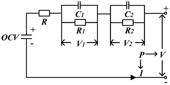
Figure 1.
Schematic of the second-order RC equivalent circuit model using power as the input.
In Figure 1, represents the input to the model, i.e., the power required by the external circuit; represents the terminal voltage; denotes the current, with the charge direction defined as the positive direction; represents the open circuit voltage, which is affected by SOC and temperature; and represent the polarization voltages; represents the ohmic resistance; and represent the two polarization internal resistances respectively; and are the polarization capacitors. All the parameters in the model, except for the input current , are dependent on SOC and temperature of the battery; the terminal voltage will change as the foregoing parameters change.
The terminal voltage is expressed as:
The required power is:
According to the Kirchhoff’s law, the two polarization voltages can be expressed as:
where, is the rate of change in , and is the rate of change in .
The battery SOC can be calculated by using the Ampere hour integral method as follows:
where, is the SOC value at time t, is the SOC value at time , and is the maximum capacity available.
The above five formulas are continuous equations of the battery model. If the sampling time is t(s), then the continuous equations can be discretized as follows:
where,
From Equations (6) and (7), a quadratic equation with one variable can be obtained as follows:
where,
Then the voltage and current at the moment are:
The parameters to be identified in the electrical model can be expressed in the following vector form:
2.2. Thermal Model of LIBs
Establishing an appropriate heat generation rate model for calculating the heat generation behavior of a battery is crucial to the accuracy of the battery’s thermal model. Since the thermal model in the present study is a second-order RC equivalent circuit model, a dynamic heat generation rate model suitable for the RC equivalent circuit is proposed based on the Bernardi heat generation model [20]:
where, is the order of the RC equivalent circuit, is the polarization voltage of the th RC element, and is the polarization resistance of the th RC element.
Following that, an EENT model is established with the proposed heat generation rate model (as shown in Equation (8)) as input. For simplification, the following assumptions are made upon modeling: (1) thermo-physical parameters of the LIB are fixed, (2) radiation and internal convection of the LIB are not considered, (3) heat generation of the LIB is uniform, and (4) aluminum housing of the LIB has high thermal conductivity and uniform temperature distribution. The schematic of the thermal model is shown in Figure 2.
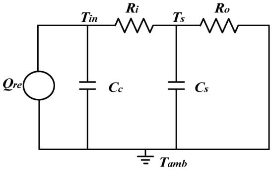
Figure 2.
Schematic of a two-state lumped parameter thermal network model.
In Figure 2, and correspond to the heat capacity of the medium inside the LIB and of the shell; and are the thermal resistance from the inside to the surface of the LIB and from the LIB surface to the surrounding medium; , and are the ambient temperature, the LIB surface temperature and the LIB internal temperature. This thermal model can be mathematically represented by:
If:
Formula (13) can be simplified into the following:
Equation (15) can be converted through Laplace transformation into:
By rearrangement of Equation (16), the difference between the internal/surface temperature and the ambient temperature can be obtained:
Parameters to be identified for the proposed thermal model come below:
Figure 3 shows the schematic of a power input electro-thermal model. According to the schematic, the terminal voltage and current of the battery are simulated based on the current power requirement, SOC and battery temperature by using the equivalent circuit model; resistance, current and other electrical parameters are input into the heat generation model to calculate the heat generation rate of the battery; then the heat generation rate so obtained is used as input to the EENT model to calculate the internal temperature and surface temperature of the battery and feed back the average temperature of the battery to the electrical model for subsequent calculation, in realization of bi-directional coupling of the electro-thermal model. Through data sharing and iterative computation in between the sub-models, electrical dynamic response and temperature distribution of the LIB can be estimated online.

Figure 3.
Schematic of the proposed power input electro-thermal model.
3. Experiment and Model Parameter Identification of LIBs
For parameter identification and experimental verification of the models proposed in this paper, electrical and thermal characteristics of an NCR18650 LIB were tested under different conditions using a thermostat (HL404C), a battery testing equipment (BTS-5 V 100 A), and a thermocouple. The measurement accuracy of current, voltage, and temperature are ±0.1 mA, ±0.1 mV, and ±0.1 °C, respectively. The battery parameters are given in Table 1.

Table 1.
Main parameters of the battery.
According to the test scheme and identification method proposed in [24], equivalent circuit model parameters under different temperatures, SOC values, and current directions can be obtained through the static capacity test (SCT), hybrid pulse power characteristic (HPPC) test, and double pulse discharge test. According to the results of SCT test and double pulse discharge test, the OCV and capacity of the battery under different conditions can be obtained directly. Other parameters are identified by HPPC test data and the specific parameter identification method refers to [24]. All parameter identification is based on Matlab platform [25]. Electrical model parameters identified are shown in Figure 4 below.
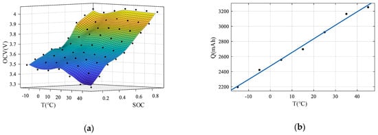
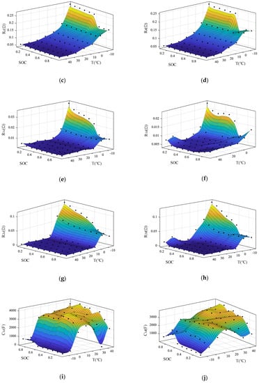
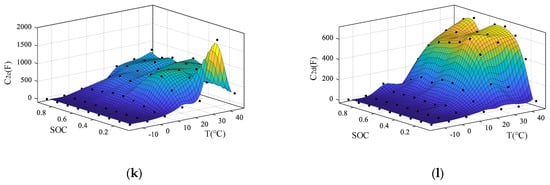
Figure 4.
Parameters identified of the equivalent circuit model: (a) Open circuit voltage OCV; (b) Capacity Q; (c) Charging ohmic internal resistance Rc; (d) Discharging ohmic internal resistance Rd; (e) Charging polarization internal resistance R1c; (f) Discharging polarization internal resistance R1d; (g) Charge polarization internal resistance R2c; (h) Discharging polarization internal resistance R2d; (i) Charge polarization capacitance C1c; (j) Discharging polarization capacitance C1d; (k) Charge polarization capacitor C2c; (l) Discharging polarization capacitor C2d.
As can be seen from Figure 4, the changes of battery parameters with temperature and SOC are very obvious. At low temperatures, the internal resistance of the battery increases obviously, while the variation of capacitance parameters with temperature is roughly the opposite.
In this study, the approach proposed in [22] is used to identify parameters of the established thermal model by direct measurement method, including the temperature entropy coefficients under different SOC (the results are shown in Figure 5); the thermal resistance and heat capacity under the 1.5 C pulse discharging condition are identified by means of the least square method, with the identification process shown in Figure 6 and results given in Table 2. It should be noted that in the present study, the parameters of thermal model at different SOCs and temperatures are regarded as constant, and the effect of battery aging is also not considered.
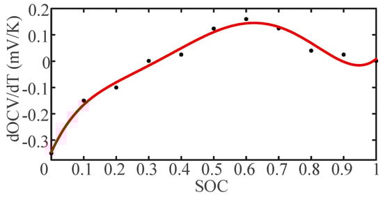
Figure 5.
Parameter identification results of the temperature entropy coefficient.
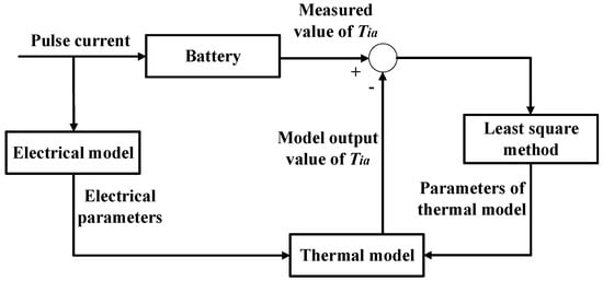
Figure 6.
Schematic diagram of thermal model parameter identification.
Table 2.
Identification parameters of the thermal model.
4. Accuracy Verification and Result Analysis of the Electro-Thermal Model
This section relates to accuracy verification with respect to simulation of the voltage and surface temperature with the PIET model, as well as to comparative accuracy analysis between the PIET model and the PIIR model with the ambient temperature as input, which is intended to illustrate the necessity of establishing an electro-thermal model. In order to verify the temperature adaptability of the model, verification experiments were carried out under seven different ambient temperature conditions, i.e., −15 °C, −5.6 °C, 4.1 °C, 16 °C, 25.5 °C, 34.5 °C, and 44 °C. Please note that all simulations are based on the Matlab platform.
In this study, the battery was loaded with 10 continuous powers under FUDS operating conditions (battery discharging and charging power under control) to verify the accuracy of the PIET model. Considering the sharp decline of battery performance under sub-zero temperature conditions, the power loaded under FUDS operating conditions when the ambient temperature is sub-zero was reduced to half of that when the ambient temperature was above zero, as shown in Figure 7. In the figure, negative power stands for discharging, and positive power for charging. Powers corresponding to the seven operating conditions are shown in Table 3.
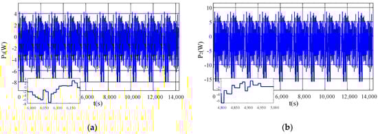
Figure 7.
Power load of the battery: (a) When the ambient temperature is below zero; (b) When the ambient temperature is above zero.
Table 3.
Sequence of operating conditions.
4.1. Model Accuracy Verification under Working Condition 1
The model accuracy verification result under operating condition 1 is shown in Figure 8. It can be seen from Figure 8 that the simulation results of the PIET model and the PIIR model are quite different. Since polarization of the LIB is not considered in the PIIR model, the terminal voltage in the PIIR model is higher during discharging, but lower during charging than that in the PIET model. Therefore, under the same discharging power requirement, the current is higher in the PIET model during discharging but lower during charging than that in the PIIR model. As the battery continues operation, the SOC of the battery and the terminal voltage under the same discharging power requirement drop, while the discharging current and the temperature of the battery gradually rises, indicating that the error gradually increases in the PIIR model relative to the PIET model. Comparatively, the simulated voltage root mean square error (RMSE) is 19.38 mV in case of the PIET model and 39.38 mV in case of the PIIR model; the current RMSE is 6.75 mA in case of the PIET model and 9.79 mA in case of the PIIR model. Besides, in case of the PIET model, the maximum temperature rise of the battery is 2.41 °C, the maximum temperature difference between inside and outside of the battery is 0.42 °C, the RMSE of the surface temperature is 0.14 °C and the measurement error of the sensor is ±0.2 °C, indicating that the model can describe battery temperature changes more accurately.
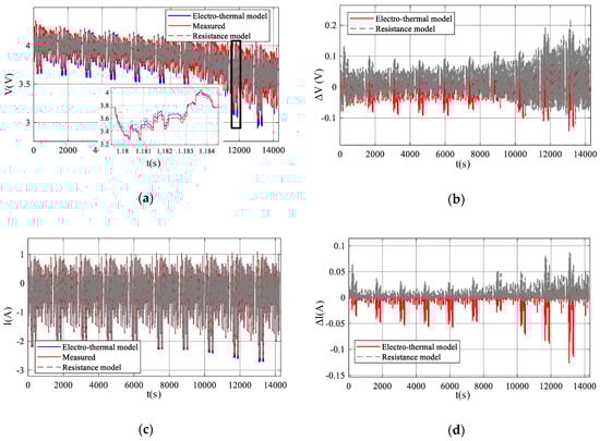
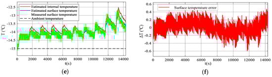
Figure 8.
Verification results under Condition 1: (a) Terminal voltage; (b) Terminal voltage error; (c) Current; (d) Current error; (e) Temperature; (f) Surface temperature error.
4.2. Model Accuracy Verification under Working Condition 2
The model accuracy verification result under operating condition 2 is shown in Figure 9. In operating condition 2, the ambient temperature of the battery is increased compared with that in operating condition 1. Under the same discharging power requirement, the battery terminal voltage increases due to decrease in the internal resistance of the battery and thus the absolute value of the discharging current decreases. Due to decrease in the internal resistance of the battery, the heat generation and temperature rise of the battery under this condition also decrease. Since the change rate of the battery’s internal resistance decreases with temperature rise of the battery, both the PIET model and the PIIR model have improved accuracy of voltage estimation, while the accuracy difference between the two models is reduced. The simulated voltage RMSE is 18.12 mV in case of the PIET model and 34.63 mV in case of the PIIR model; the current RMSE is 3.62 A in case of the PIET model and 8.56 mA in case of the PIIR model. In the PIET model, the maximum temperature rise of the battery is 1.38 °C, the maximum temperature difference between inside and outside is 0.23 °C, and the RMSE of the surface temperature is 0.12 °C.
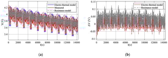
Figure 9.
Verification results under Condition 2: (a) Terminal voltage; (b) Terminal voltage error; (c) Current; (d) Current error; (e) Temperature; (f) Surface temperature error.
4.3. Model Accuracy Verification under Operating Condition 3
The model accuracy verification result under the operating condition 3 is shown in Figure 10. In operating condition 3, both the current and the range of battery terminal voltage change increase due to multiplication of the required power compared with working condition 2. The significant impact imposed by multiplication of the current on temperature rise results in a higher temperature rise of the battery and a larger temperature difference between the inside and outside of the battery, even though the temperature rise causes a decrease in the internal resistance of the battery to some extent. The simulated voltage RMSE is 17.43 mV in case of the PIET model and 18.61 mV in case of the PIIR model; the current RMSE is 9.51 A in case of the PIET model and 10.61 mA in case of the PIIR model. In the PIET model, the RMSE of the surface temperature is 0.18 °C.
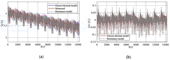
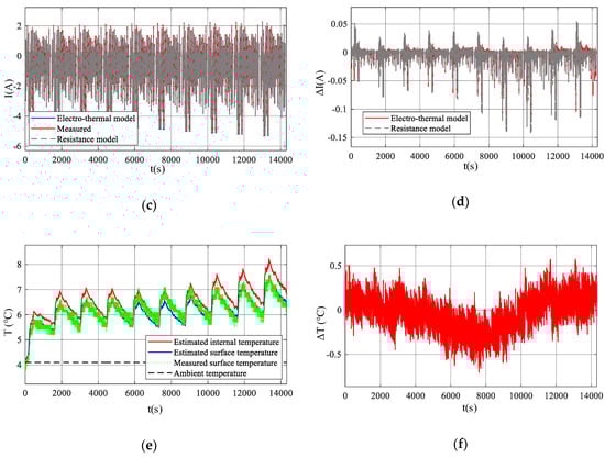
Figure 10.
Verification results under Condition 3: (a) Terminal voltage; (b) Terminal voltage error; (c) Current; (d) Current error; (e) Temperature; (f) Surface temperature error.
In operating conditions 4–7, the ambient temperature gradually rises with the loaded power remaining unchanged. No further illustration will be provided for these conditions in this article. For detailed data, refer to Table 4.
Table 4.
Comparative analysis of model accuracy.
4.4. Result Analysis
The main simulation parameter errors of the PIET model and the PIIR model are shown in Table 4. The following rules can be obtained according to analysis of the accuracy verification results under operating conditions in the table:
- With increase of the ambient temperature, the PIET model and the PIIR model will have gradually improved accuracy due to the decrease in internal resistance and accurate parameter identification;
- When the temperature goes down below zero, the performance parameters of the battery increase sharply at the same temperature gradient, and the time constant reflecting the battery polarization decreases sharply. Therefore, the polarization voltage described by the two RC originals increases sharply. In addition, temperature rise of the battery per se in low temperature conditions has a greater impact on electrical performance than normal temperature. Therefore, the voltage and current estimation accuracy of the PIET model is significantly higher than that of the PIIR model under conditions 1 and 2.
According to the model accuracy verification results and regular analysis above, it is known that the PIET model can accurately describe the dynamic response of the battery under specific power load conditions. In addition, the PIET model has significantly improved accuracy relative to the PIIR model under the same parameter identification accuracy conditions and in the same low temperature and high power load conditions.
5. Conclusions
In this paper, a PIET model is proposed. The model can accurately reflect the electrical dynamic response of the battery and capture changes in the surface and internal temperature of a battery for EV simulation systems. First, the PI2sRCEC model is established, and a dynamic heat generation rate model suitable for RC equivalent circuits is built. Then the electric model is combined with the 2sLPTN model through the heat generation rate model to obtain the PIET model.
Following parameter identification of the electrical and thermal model, the battery model was verified regarding accuracy under seven operating conditions. According to the model accuracy verification results and regular analysis, it is known that the maximum root mean square error in voltage estimation, current estimation, and surface temperature estimation is 19.38 mV, 9.51 mA, and 0.19 °C respectively, and the PIET model can accurately describe the dynamic response of the battery under specific power load conditions. In addition, the PIET model has significantly improved accuracy than the PIIR model under the operating conditions of low temperature and high power load.
Since the model is only verified at the ambient temperature of −15 °C to 44 °C, the accuracy cannot be guaranteed if outside this temperature range. Besides, the accuracy cannot be guaranteed for aging batteries since the model parameters will be changed.
Author Contributions
Conceptualization, B.H., M.H. and C.F.; methodology, B.H., L.C. and K.C.; software, L.C. and C.F.; validation, M.H., G.J. and S.L.; formal analysis, B.H., D.W. and C.F.; investigation, B.H. and S.L.; data curation, L.C. and G.J.; writing—original draft preparation, B.H., M.H. and D.W.; writing—review and editing, B.H., K.C. and L.C.; visualization, S.L.; supervision, M.H. and D.W.; project administration, M.H. and K.C. All authors have read and agreed to the published version of the manuscript.
Funding
This research was funded by the National Key R&D Program of China under grant 2018YFB0106100, the Foundation of Artificial Intelligence Key Laboratory of Sichuan Province under grant 2020RYY01, the National Natural Science Foundation of China under grant 52072053, and the Science & Technology Department of Sichuan Province under grant 2021YFG0050.
Conflicts of Interest
The authors declare no conflict of interest.
References
- Choi, J.W.; Aurbach, D. Promise and reality of post-lithium-ion batteries with high energy densities. Nat. Rev. Mater. 2016, 1, 16013. [Google Scholar] [CrossRef]
- Wu, D.; Guo, F.; Field, F.R.; Kleine, R.D.; Kim, H.C.; Wallington, T.J.; Kirchain, R.E. Regional heterogeneity in the emissions benefits of electrified and lightweighted light-duty vehicles. Environ. Sci. Technol. 2019, 53, 10560–10570. [Google Scholar] [CrossRef] [Green Version]
- Zhang, D.H.; Wang, J.Q.; Lin, Y.G.; Si, Y.L.; Huang, C.; Yang, J.; Huang, B.; Li, W. Present situation and future prospect of renewable energy in China. Renew. Sustain. Energy Rev. 2017, 76, 865–871. [Google Scholar] [CrossRef]
- Diouf, B.; Pode, R. Potential of lithium-ion batteries in renewable energy. Renew. Energy 2015, 76, 375–380. [Google Scholar] [CrossRef]
- Hu, J.; Morais, H.; Sousa, T.; Lind, T. Electric vehicle fleet management in smart grids: A review of services, optimization and control aspects. Renew. Sustain. Energy Rev. 2016, 56, 1207–1226. [Google Scholar] [CrossRef] [Green Version]
- Jiang, L.; Yin, C.; Wu, H.; Zhang, X. A transfer function type of simplified electrochemical model with modified boundary conditions and Padé approximation for Li-ion battery: Part 2. Modeling and parameter estimation. J. Power Sources 2017, 352, 258–271. [Google Scholar]
- Li, J.; Wang, L.; Lyu, C.; Liu, E.; Xing, Y.; Pecht, M. A parameter estimation method for a simplified electrochemical model for Li-ion batteries. Electrochim. Acta 2018, 275, 50–58. [Google Scholar] [CrossRef]
- Zou, C.; Hu, X.; Wei, Z.; Wik, T.; Egardt, B. Electrochemical estimation and control for lithium-ion battery health-aware fast charging. IEEE Trans. Ind. Electron. 2017, 65, 6635–6645. [Google Scholar] [CrossRef]
- Li, X.; Yuan, C.; Wang, Z. State of health estimation for Li-ion battery via partial incremental capacity analysis based on support vector regression. Energy 2020, 203, 117852. [Google Scholar] [CrossRef]
- Sheng, H.; Xiao, J. Electric vehicle state of charge estimation: Nonlinear correlation and fuzzy support vector machine. J. Power Sources 2015, 281, 131–137. [Google Scholar] [CrossRef]
- Nejad, S.; Gladwin, D.T.; Stone, D.A. A systematic review of lumped-parameter equivalent circuit models for real-time estimation of lithium-ion battery states. J. Power Sources 2016, 316, 183–196. [Google Scholar] [CrossRef] [Green Version]
- Cho, S.; Jeong, H.; Han, C.; Jin, S.; Lim, J.H.; Oh, J. State-of-charge estimation for lithium-ion batteries under various operating conditions using an equivalent circuit model. Comput. Chem. Eng. 2012, 41, 1–9. [Google Scholar] [CrossRef]
- Zhu, Y.; Tatarchuk, B.J.; Zhu, W.H. A simplified equivalent circuit model for simulation of Pb-acid batteries at load for energy storage application. Energy Convers. Manag. 2011, 52, 2794–2799. [Google Scholar] [CrossRef]
- Hu, M.; Li, Y.; Li, S.; Fu, C.; Qin, D.; Li, Z. Lithium-ion battery modeling and parameter identification based on fractional theory. Energy 2018, 165, 153–163. [Google Scholar] [CrossRef]
- Yi, J.; Lee, J.; Shin, C.B.; Han, T.; Park, S. Modeling of the transient behaviors of a lithium-ion battery during dynamic cycling. J. Power Sources 2015, 277, 379–386. [Google Scholar] [CrossRef]
- Richardson, R.R.; Zhao, S.; Howey, D.A. On-board monitoring of 2-D spatially-resolved temperatures in cylindrical lithium-ion batteries: Part I. Low-order thermal modelling. J. Power Sources 2016, 326, 377–388. [Google Scholar] [CrossRef] [Green Version]
- Schmidt, J.P.; Arnold, S.; Loges, A.; Werner, D.; Wetzel, T.; Ivers-Tiffée, E. Measurement of the internal cell temperature via impedance: Evaluation and application of a new method. J. Power Sources 2013, 243, 110–117. [Google Scholar] [CrossRef]
- Zhu, J.G.; Sun, Z.C.; Wei, X.Z.; Dai, H.F. A new lithium-ion battery internal temperature on-line estimate method based on electrochemical impedance spectroscopy measurement. J. Power Sources 2015, 274, 990–1004. [Google Scholar] [CrossRef]
- Bernardi, D.; Pawlikowski, E.; Newman, J. A general energy balance for battery systems. J. Electrochem. Soc. 1985, 132, 5. [Google Scholar] [CrossRef] [Green Version]
- Lin, X.; Perez, H.E.; Mohan, S.; Siegel, J.B.; Stefanopoulou, A.G.; Ding, Y.; Castanier, M.P. A lumped-parameter electro-thermal model for cylindrical batteries. J. Power Sources 2014, 257, 1–11. [Google Scholar] [CrossRef]
- Dai, H.; Zhu, L.; Zhu, J.; Wei, X.; Sun, Z. Adaptive Kalman filtering based internal temperature estimation with an equivalent electrical network thermal model for hard-cased batteries. J. Power Sources 2015, 293, 351–365. [Google Scholar] [CrossRef]
- Chen, L.; Hu, M.; Cao, K.; Li, S.; Su, Z.; Jin, G.; Fu, C. Core temperature estimation based on electro-thermal model of lithium-ion batteries. Int. J. Energy Res. 2020, 44, 5320–5333. [Google Scholar] [CrossRef]
- Qi, X.; Wang, Q.; Xie, F.; Cao, J.; Chen, L.; Zhan, Q. Researching of efficiency optimized torque distribution based on front and rear wheel independently drive electrical vehicle. In Proceedings of the 19th International Conference on Electrical Machines and Systems (ICEMS 2016), Chiba, Japan, 13–16 November 2016; pp. 1–6. [Google Scholar]
- Xu, Y.; Hu, M.; Fu, C.; Cao, K.; Su, Z.; Yang, Z. State of Charge Estimation for Lithium-Ion Batteries Based on Temperature-Dependent Second-Order RC Model. Electronics 2019, 8, 1012. [Google Scholar] [CrossRef] [Green Version]
- Torchio, M.; Magni, L.; Gopaluni, R.B.; Braatz, R.D.; Raimondo, D.M. Lionsimba: A matlab framework based on a finite volume model suitable for li-ion battery design, simulation, and control. J. Electrochem. Soc. 2016, 163, A1192–A1205. [Google Scholar] [CrossRef]
Publisher’s Note: MDPI stays neutral with regard to jurisdictional claims in published maps and institutional affiliations. |
© 2021 by the authors. Licensee MDPI, Basel, Switzerland. This article is an open access article distributed under the terms and conditions of the Creative Commons Attribution (CC BY) license (https://creativecommons.org/licenses/by/4.0/).