Article

Wearable Textile Antenna with a Graphene Sheet or Conductive Fabric Patch for the 2.45 GHz Band

by
Theodoros N. Kapetanakis
1,
Christos D. Nikolopoulos
1,2,
Konstantinos Petridis
1 and
Ioannis O. Vardiambasis
1,*
1
Department of Electronic Engineering, Hellenic Mediterranean University, 73133 Chania, Crete, Greece
2
School of Electrical and Computer Engineering, National Technical University of Athens, 15780 Zografou, Athens, Greece
*
Author to whom correspondence should be addressed.
Electronics 2021, 10(21), 2571; https://doi.org/10.3390/electronics10212571
Submission received: 15 September 2021 / Revised: 14 October 2021 / Accepted: 18 October 2021 / Published: 21 October 2021
(This article belongs to the Special Issue Textile and Wearable Antennas)

Abstract

:
Textile patch antennas of simple rectangular, triangular, and circular shape, for operation in the 2.4–2.5 GHz free industrial, scientific, and medical (ISM) band, are designed in this paper. Thirty-six patch antenna prototypes have been fabricated by engaging different patch geometries, patch materials, and substrate materials. Each patch antenna is designed after optimization by a genetic algorithm, which evolves the initial dimensions and feeding position of the prototype’s microstrip counterpart to the final optimal geometrical characteristics of the wearable prototype (with the originally selected shape and materials). The impact of the design and fabrication details on antenna performance were thoroughly investigated. Graphene sheet patches were tested against conductive fabric and copper sheet ones, while denim and felt textile substrates were competing. The comparative study between a large number of different graphene, all, and copper textile prototypes, which revealed the excellent suitability of graphene for wearable applications, is the main contribution of this paper. Additional novelty elements are the compact, flexible, and easy-to-fabricate structure of the proposed antennas, as well as the use of state-of-the-art conductive materials and commercially available fabrics and the extensive investigation of many prototypes in various bending conditions. Simulations and measurements of the proposed antennas are in very good agreement. All fabricated prototypes are characterized by flexibility, light weight, mechanical stability, resistance to shock, bending and vibrations, unhindered integration to clothes, low-cost implementation, simple, time-saving, and industry-compatible fabrication process, and low specific absorption rate (SAR) values (computed using rectangular and voxel models); the graphene prototypes are additionally resistant to corrosion, and the circular ones have very good performance under bending conditions. Many antenna prototypes demonstrate interesting characteristics, such as relatively wide bandwidth, adequate gain, firm radiation patterns, coverage of the ISM band even under bending, and very low SAR values. For example, the circular graphene patch (with 55.3 mm diameter attached upon a 165.9 × 165.9 mm) felt substrate CGsF1 prototype accomplishes 109 MHz measured bandwidth, 5.45 dBi gain, 56% efficiency, full coverage of the ISM band under bending, and SAR less than 0.003 W/Kg.

1. Introduction

Body-centric communications are at the heart of all modern biomedical, healthcare, entertainment, sportive, identification, commercial, and military system applications. Communications around, upon, or within human bodies have managed to gather huge research resources over the preceding years and still experience increasing expansion [1,2,3]. The corresponding antennas have to be wearable, characterized by flexibility, conformability, and stretchability, in order to suit curvilinear surfaces and endure dynamic motions [4,5,6]. The development of flexible conductive materials has activated the rise of new antenna designs and various innovative applications that were not possible with the old, rigid structures. Thus, wearable antennas are rapidly becoming integrable parts of flexible electronic devices and sensors, smart watches, smart cards, future mobile phones, laptop and palmtop computers, telemedicine and healthcare systems, health-monitoring and clinic therapeutic devices, medical microwave radiometers, radio frequency identification tags, vehicular navigation systems, and the whole internet of things (IoT) industry, in order to seamlessly and invisibly communicate and exchange information and data between machines, technology, and humans [3,4,5,7].
The most obvious, and probably the best, technique making an antenna or sensor wearable is its integration into clothing. Textile antennas are flexible, thin, robust, inexpensive, low profile, light weight, resistant to daily usage, durable to washing, and easily interconnected. They may be easily embedded into everyday everybody’s clothing, serving all kind of body-centric, medical, military, and commercial applications in the most promising way, as ideal smart interfaces for interaction between humans and technology [5,8]. Thus, designing and fabricating textile wearable antennas is a truly difficult and promising task, because of all the previously mentioned advantages, along with these antennas’ full capability to integrate and interconnect with microwave devices and radio frequency circuits, accomplishing very good results [9,10,11,12,13,14].
Besides the UHF band, the 2.4–2.5 GHz frequency range is extensively used for wearable industrial, scientific, and medical (ISM) applications. For example, wearable textile logo antennas are proposed in [15,16], while several flexible antennas are designed in [17,18,19,20,21] for various on-body applications.
Various geometries and configurations of wearable and textile antennas have been introduced and implemented recently by many researchers. The relative literature is vast. To mention a few: Ref. [22] proposes an RFID-embroidered metamaterial, antenna; Ref. [15] presents logo-shaped, colorful, textile antennas; Ref. [23] realizes, in textile technology, a half-mode, folded, rectangular antenna, integrated on substrate cavity; Ref. [24] implements a circular, ring-slot, fabric antenna, integrated on a waveguide, cavity-fed substrate; Ref. [25] constructs another integrated, mixed-embroidered, woven, textile, waveguide antenna; Ref. [26] reports a dipole antenna, on the Kapton polyimide substrate, for flexible display devices; Ref. [27] fabricates a slotted patch antenna on e-textile, created with sewed copper tape; Ref. [28] fabricates an embroidered, meander ring, dipole antenna; Ref. [29] introduces cotton or denim substrates to slit loaded textile antennas; and Refs. [10,11] embroidered fractal bowtie antennas.
On the other hand, microstrip patch antennas, of various geometries, due to their compact size, light weight, low profile, planar configuration, easy fabrication, convenient modularization, high reliability, simple integrability with solid state devices, and low cost, are important, in both theoretical research and engineering applications, and widely used as transmitting antennas, despite their limited usable frequency bandwidth and low gain [30,31,32,33,34,35,36,37,38,39,40]. As wearable electronics are recognized as very hot topic in today’s research endeavor, the recent trend is to replace traditional metallic materials, such as copper, with novel promising materials, such as graphene, the allotrope of carbon nanotube [41]. Research evolution in material science led to the use of graphene as a very advantageous material for the design and fabrication of RF, microwave, and millimeter-wave devices [42]. Especially, the improvements of its material properties and characteristics, such as its adequate electrical conductivity, in combination with its light weight (about 5 times less than copper [43]), structural stability, and mechanical flexibility, reveal graphene as one of the most efficient novel materials for flexible antennas. For example, Ref. [44] proposes a highly conductive, graphene assembly film RFID tag antenna, with a performance corresponding to that of the available in-market metallic antennas; Ref. [45] presents a frequency-reconfigurable microstrip antenna for satellite communications, where the multilayer antenna is fabricated from graphene-conductive, ink-printed textile (as an alternative of metals), after its experimental comparison with a traditional copper antennas; Ref. [46] suggests an UWB elliptical, quasi-dipole antenna, printed onto kapton substrate and measured in the frequency range of 1–5 GHz, with 2 dBi gain at 2 GHz, and revealed stable resistance after numerous bending cycles during flexibility tests; and Ref. [47] uses the water transfer method to print a graphene-based antenna on paper substrate, having 0.7 dBi max gain and 8.9% fractional bandwidth. Instead of the aforementioned graphene antennas using flexible materials (such as Kapton, photopaper, etc.) as substrates, herein we suggest the graphene sheet (in comparison to the conductive fabric and the copper sheet) as a conductive material for patches of various simple geometries, using substrates made of commercially-available fabrics that are widely used in the clothing industry.
Another issue of concern in wearable devices is the multilevel interaction between antennas and tissues, since the effects of human body proximity on antenna characteristics are well known [6,48,49,50,51]. Moreover, it is always necessary to comply with the standards, regulations, and limits for the electromagnetic energy absorbed by human tissues [52,53,54].
Textile rectangular, triangular, and circular probe-fed patch antennas are presented in this paper for operation in the free 2.45 GHz ISM band. Thirty-six different prototypes were optimized, designed, simulated, fabricated, measured, compared, and presented using three different conductive materials (graphene sheet, conductive fabric, and copper sheet) for the active patch, four different textiles (thin and thick denim, thin and thick felt) for the antenna substrate, and three different geometrical shapes. Even though the investigated patch antennas have classical geometries, which have been successfully used by other researchers in the past, the main contribution and novelty of this work is the comparative study of graphene textile antennas versus all textile antennas. Additional novelty elements are: (i) the compact, flexible, and easy-to-fabricate structure of the patch antenna prototypes, in combination with the use of state-of-the-art conductive materials, such as graphene, and commercially available fabrics, such as denim and felt; (ii) the comparative study of a large number of different antenna prototypes in various bending conditions; (iii) the relatively simple, low-cost, and time-saving fabrication process, which could potentially lead to mass production; and (iv) the low SAR values, caused by graphene textile antennas and computed using rectangular and voxel models. In order to document the aforementioned novelty elements of the present paper and to place the proposed antennas in the context of the available literature, we have dedicated Section 3.5 to extensive comparisons with related works.
A flowchart of the present work is graphically shown in Figure 1 and arranged in four Sections. Section 2 presents the geometries of the antennas under study, the methodology to determine the prototypes dimensions, and the fabrication procedure, while Section 3 discusses the simulated and measured antenna performance results (resonant frequency, reflection coefficient, standing wave ratio, bandwidth, fractional bandwidth, gain, directivity, efficiency, radiation patterns, and SAR values from two different models), under normal and bending conditions, for 36 different prototypes. A comparison with other related works is also presented in Section 3, where the advantages of the graphene patch, the circular shape, and the lower-loss substrate are revealed, confirming the suitability of graphene textile antennas for wearable applications. Final conclusions are drawn in Section 4.

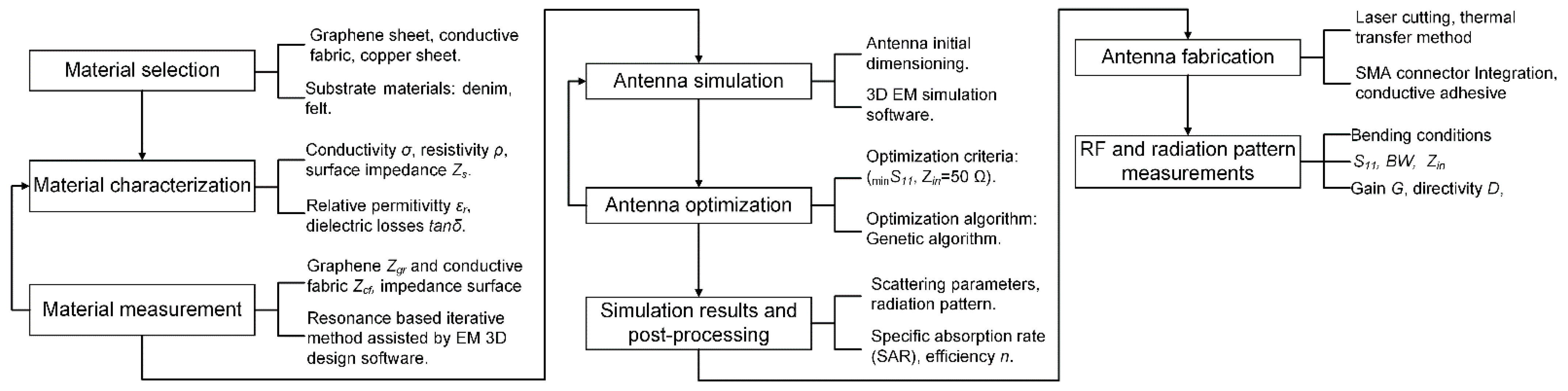
2. Materials and Methods

For each of the proposed herein prototypes, a different combination of radiator’s conducting material (graphene sheet, conductive fabric, or copper sheet), substrate’s dielectric material (thin denim, thick denim, thin felt, or thick felt), and patch’s geometrical shape (rectangular, triangular, or circular) is chosen. These three originally selected characteristics are the fundamental antenna design factors; upon which, the exact geometrical characteristics of each prototype will be computed, in order to perform efficiently in the 2.4–2.5 GHz ISM band. The design of each textile patch antenna is performed in 2 stages: (1) the initialization stage, during which we use known theoretical models for the corresponding classical microstrip structures [55] to determine the approximate dimensions of the homologous microstrip antenna resonating at 2.45 GHz, and (2) the optimization stage, during which we use the genetic algorithm tool of CST 2021 [56] to evolve the initial sketchy dimensions to their exact optimal values.

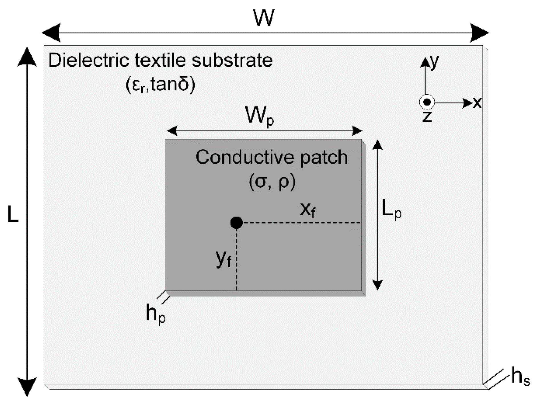
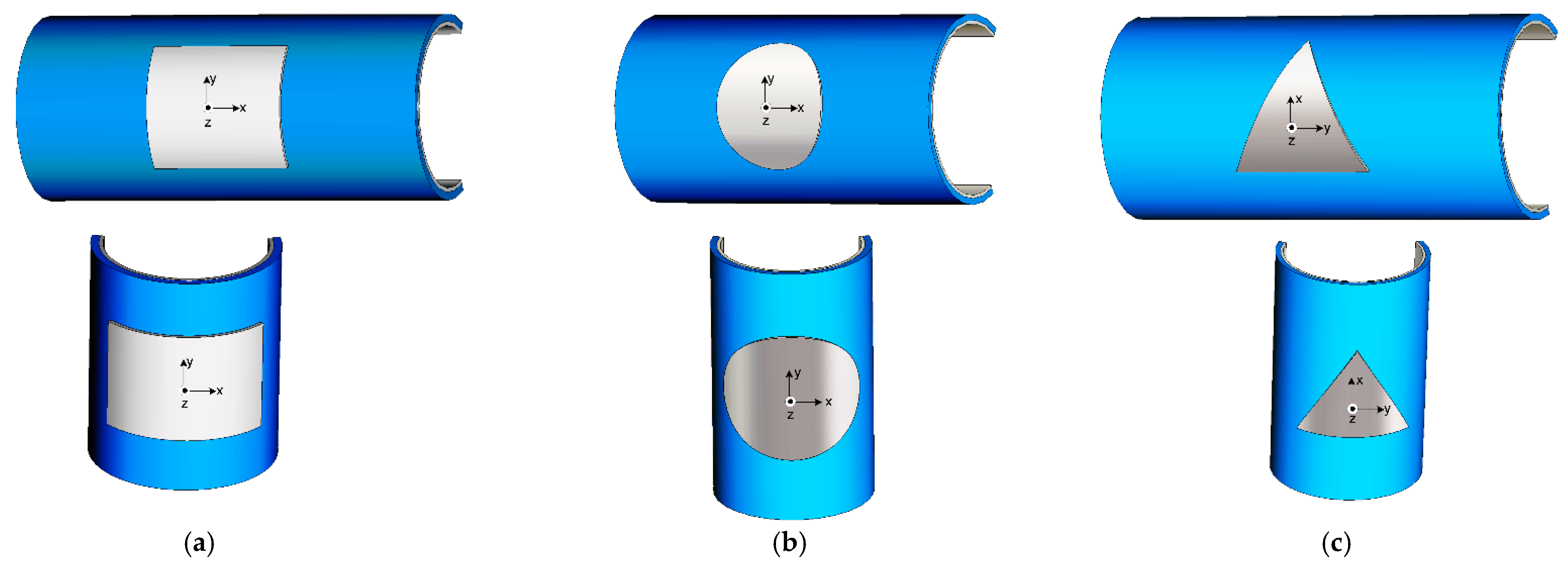
2.1. Rectangular Patch Antenna Design

The geometry of the wearable, rectangular, under-study antenna is shown in Figure 2, where a probe-fed, rectangular microstrip patch is illustrated as a structure consisting of 5 layers: (1) the upper-layer radiator, which is a conductive rectangular patch (made of graphene sheet, conductive fabric, or copper sheet), with length Lp, width Wp, and thickness hp; (2) the ultra-thin bonding-layer (double sided thermoplastic adhesive), attaching the patch and the substrate fabrics, with length Lp, width Wp, and thickness ~10 μm; (3) the middle-layer dielectric substrate (made of denim D1, denim D2, felt F1, or felt F2 textile), with length L, width W, and thickness hs; (4) the same as before, an ultra-thin bonding-layer, now attaching the substrate and the ground-plane fabrics, with length L, width W, and thickness ~10 μm; and (5) the bottom-layer ground plane (made of the same conductive material as the upper-layer), with length L, width W, and thickness hp.
For adequate radiation efficiency, practical values of the width Wp and the length Lp of the rectangular microstrip antenna, based on the transmission-line model, are given by [55]:
W p = 1 2 f r μ 0 ε 0 2 ε r + 1
L p = 1 2 f r ε r e f f μ 0 ε 0 2 Δ L
where ε0 and μ0 are the dielectric permittivity and magnetic permeability of free space, εr is the dielectric constant of the substrate, fr is the resonant frequency, and εreff is the effective dielectric constant of the microstrip antenna.
ε r e f f = ε r + 1 2 + ε r 1 2 [ 1 + 12 h s W p ] 1 / 2
ΔL is the extension of the length on each side of the patch
Δ L h s = 0.412 ( ε r e f f + 0.3 ) ( W p h s + 0.264 ) ( ε r e f f 0.258 ) ( W p h s + 0.8 )
and hs is the height of the substrate.
The microstrip is fed by a coaxial line from underneath, at (xf, yf), as indicated in Figure 2. The feed location plays a significant role for the input impedance, but not for the resonant frequency. The distances xf and yf from the rectangular microstrip center are approximately given by [57]:
x f = W p π   sin 1 R i n R e d ,   y f = L p π   sin 1 R i n R e d
where Rin is the input resistance and Red is the input resistance at the edge. The impedance varies from 0 at the center to Red at the edge, so the feed location should be carefully positioned, in order to achieve the desirable input impedance Zin = 50 + j0 Ω. The microstrip is fed by bringing the center conductor of an SMA connector through a hole in the ground plane and substrate and connecting it electrically to the designed patch feed-point.

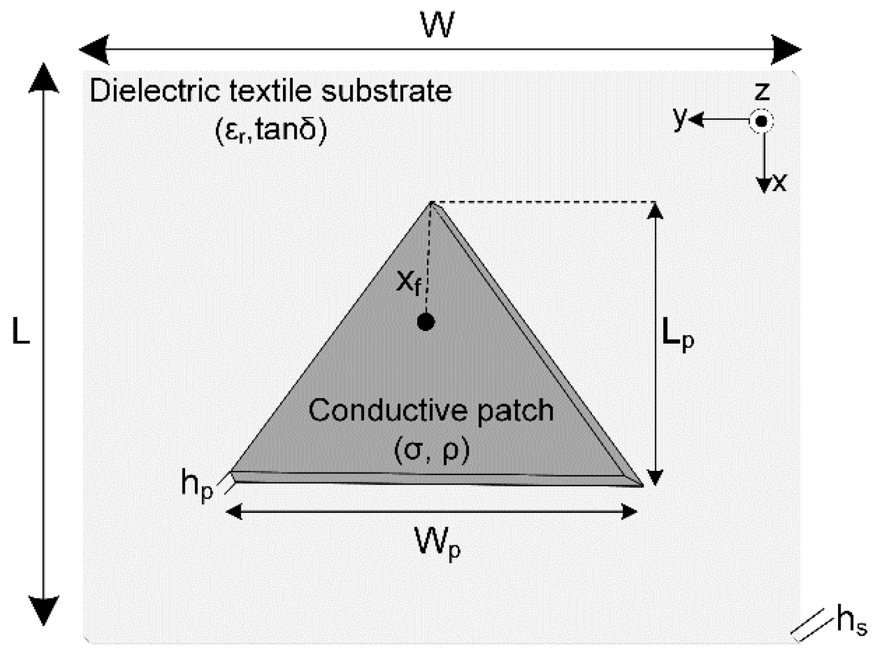
2.2. Triangular Patch Antenna Design

The geometry of the wearable, triangular, under-study antenna is shown in Figure 3, where a probe-fed, triangular microstrip patch is illustrated as a structure consisting of the same five layers described in the previous section. Here, the rectangular, upper-layer patch and the rectangular, bonding-layer adhesive of Figure 2 were replaced by an isosceles triangular conductive patch, with height Lp and base length Wp, and an equal triangular bonding-layer adhesive, respectively.
In this case, at the initialization stage, we apply, again, the transmission-line model values of the corresponding rectangular patch resonating at 2.45 GHz, and using Equations (1) and (2) we determine the approximate base length Wp and height Lp of the triangular microstrip. As indicated in Figure 3, the microstrip is fed by an SMA connector from underneath at xf; the distance of the feed-point from the triangular antenna top is, approximately, given by Equation (5).

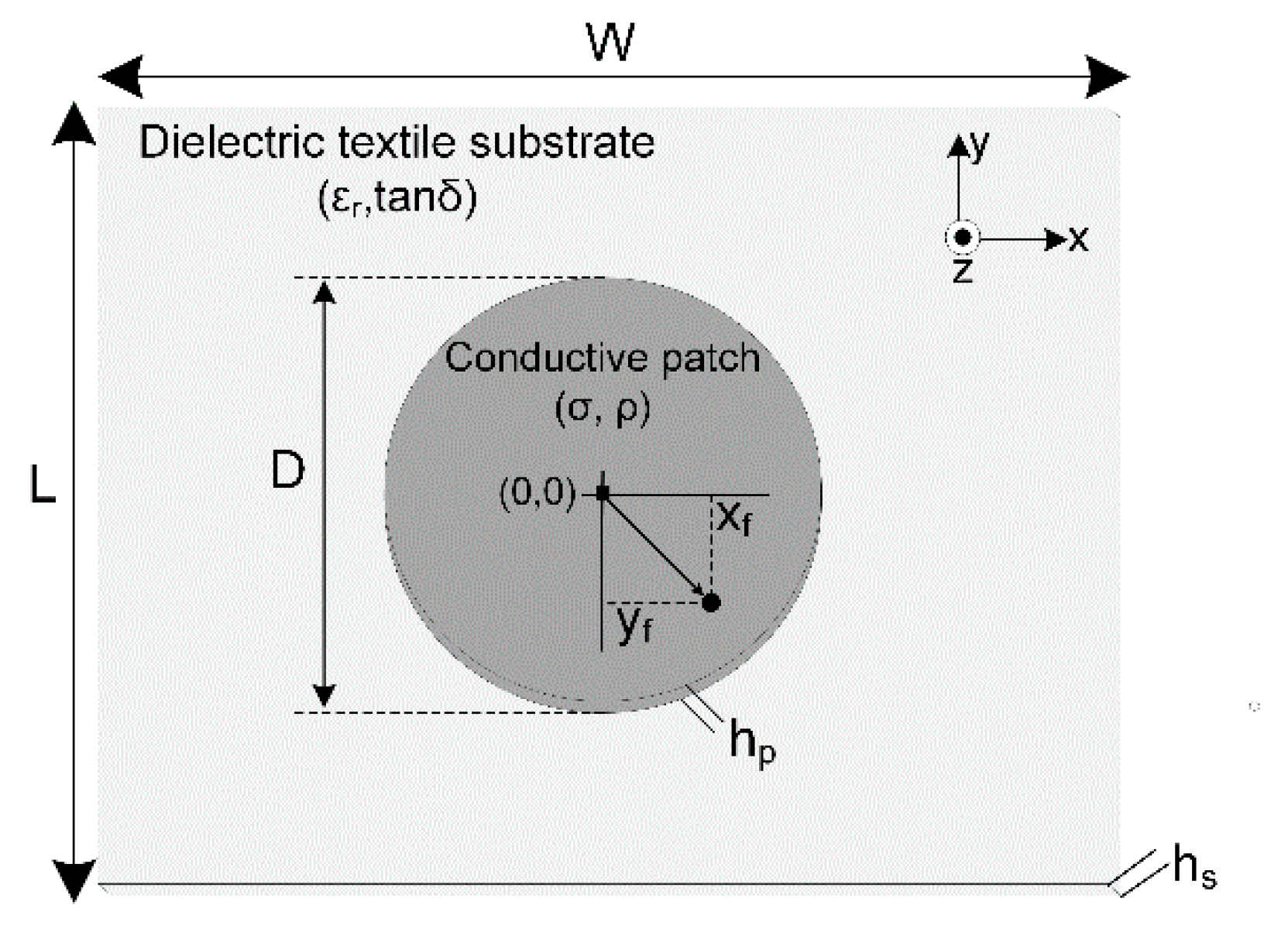
2.3. Circular Patch Antenna Design

The geometry of the wearable, circular, under-study antenna is shown in Figure 4, where a probe-fed, circular microstrip patch is illustrated as a structure consisting of the same five layers described in the previous sections. Here, the triangular, upper-layer patch and the triangular, bonding-layer adhesive of Figure 3 were replaced by a circular conductive patch of diameter D and an equal circular bonding-layer adhesive, respectively.
A practical design of the circular microstrip antenna, based on the cavity model, assumes that the diameter D is given by [55]:
D = 0.02 F 1 + 2 h s π ε r F ( ln ( π F 2 h s ) + 1.7726 ) ,   F = 10 11 8.791 f r ε r
where εr is the dielectric constant of the substrate, hs is the height of the substrate, and fr is the resonant frequency.
With correspondence to the rectangular patch case, we use Equation (5) to approximate the distances, xf and yf, of the feeding point from the microstrip center.
During the next optimization stage, a genetic algorithm will be used to evolve the initial dimensions to their exact optimal values. Aiming to design textile patch antennas for the ISM 2.45 GHz frequency band and to evaluate graphene incorporation in the design and fabrication procedure, we initialize the process by using parameters taken from Equations (1)–(6) for the antennas’ microstrip counterparts. Since the dimensions of the patch and the substrate obviously and strongly depend on the materials used, the most important design factors are the patch material, the substrate material, and the patch shape. The optimum values for the dimensions and the feeding point were obtained by using the optimization tool of CST 2021 [56]. The values of the various design parameters, as evaluated from CST, are presented in the following section for 36 different antenna prototypes.

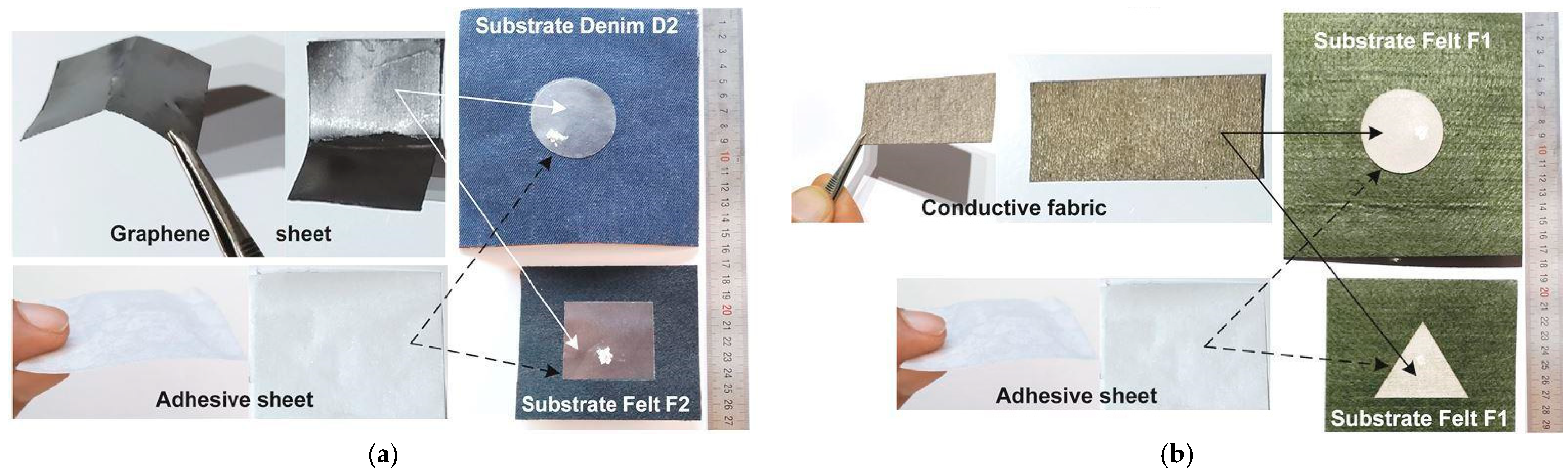
2.4. Optimized for the 2.45 GHz Patch Antenna Design and Fabrication

The approximate values, resulting from Equations (1)–(6), are the initial estimations given to the optimization genetic algorithm of the CST software [56], in order to achieve for each under-study patch antenna its final, optimized geometrical characteristics that will be used for simulation and fabrication. In each case, the exact material properties of the patch, the substrate, and the ground-plane are taken into account or properly modeled. Characteristically, both the graphene sheet and conductive fabric were modeled in CST Studio Suite [56] as ohmic sheets, in order to relate the electromagnetic fields on their ohmic sheet surface. The unknown conductivities were modeled as impedance surfaces (Zs = Rs + jXs), where both reactance (Xs) and resistance (Rs) are material properties. The impedance surface of graphene sheet (conductive fabric) is modeled as Zs,Gs = 0.338 + j2.75 (Zs,Tc = 0.35 + j1.25) at 2.45GHz, as a result of an iterative method that combined the simulations and measurements [9,58,59].
Thirty-six antennas (twelve of each shape) have been designed, simulated, fabricated, and measured, in order to mainly investigate the patch and substrate material effects on wearable antenna performance. Three different materials were used for the patch: (i) the conductive textile (Aaronia X-Dream+) copper-polyester compound [60], with thickness hp = 0.5 mm and surface resistivity ≤ 0.07 Ω/sq, designated as Tc; (ii) the graphene sheet (Sigma-Aldrich XG Leaf B 120μ) [61], with thickness hp = 0.12 mm and surface resistivity ≤ 0.06 Ω/sq, labeled as Gs; and (iii) the copper foil sheet (3M Venture Tape), with an electrically conductive acrylic adhesive [62] with thickness hp = 0.035 mm and surface resistivity ≤ 0.005 Ω/sq, titled as Cs. On the other hand, four different textiles were used for the substrate: (i) the 14oz thick denim, with thickness hs = 1.0 mm, εr = 1.63, and tanδ = 0.086, designated as D1; (ii) the 11oz thin denim, with thickness hs =0.5 mm, εr = 1.81, and tanδ = 0.073, labeled as D2; (iii) the polyester thick felt, with thickness hs =3.0 mm, εr = 1.13, and tanδ = 0.041, designated as F1; and (iv) the wool thin felt with thickness hs =1.5 mm, εr = 1.34, and tanδ = 0.039, named as F2.
The exact geometrical characteristics for the simulation and fabrication of all 36 prototypes are given in Table 1. Each prototype has a code name, consisting of three parts: (i) the first symbol “R”, “T”, or “C” stands for the rectangular, triangular, or circular shape of the patch, respectively; (ii) the second label “Tc”, “Gs”, or “Cs” corresponds to the conductive textile [60], graphene sheet [61], or copper sheet [62] material of the patch, respectively; and (iii) the third tag “D1”, “D2”, “F1”, or “F2” represents the 14oz thick denim, the 11oz thin denim, the polyester thick felt, or the wool thin felt textile of the substrate, respectively. In each case, the patch and substrate materials, lengths, and widths, as well as the feeding point position, are listed in Table 1.
As each one of the 36 prototypes of Table 1 is characterized by a unique combination of patch shape, patch material, and substrate material, their performance optimization for the 2.45 GHz band results in dimensions that differ in all cases.
All antenna prototypes have been fabricated by using a double-sided thermoplastic adhesive to bond each conductive patch with the corresponding dielectric substrate. The fabrication procedure is graphically presented in Figure 5. The graphene sheet of Figure 5a, the conductive fabric of Figure 5b, and the adhesive-sheet are cut precisely to the optimized dimensions of a rectangular, triangular, or circular patch using a CO2 BRM laser (150-Watt) and permanently attached using thermal transfer method (due to the ultra-thin bonding-layer adhesive) upon the corresponding textile substrate, previously cut to the appropriate size.
Pictures of four rectangular, four triangular, and four circular fabricated prototypes, named as RTcD1, RCsF2, RGsF2, RTcF1, TGsD1, TCsD2, TTcF1, TTcD2, CCsF1, CGsD1, CTcF1, and CTcF2 in Table 1, are presented in Figure 6. The characteristic marks on every patch correspond to the position of antenna feeding.
Regarding the interconnection between wearable antennas, mobile devices, and Internet of Things (IoT) nodes, several solutions can be proposed. In this work, we used radial 50 Ω straight flange mount SMA connectors, because of the feasibility of conventional welding methods, while the usage of UFL and FME connectors would be equally effective. Each antenna was drilled to the appropriate location (xf, yf), with a high precision laser machine, creating a hole with ~0.8 mm diameter. This way, the pin of the SMA connector passed through the ground-plane and the substrate, in order to establish an electrical connection with the conductive patch. A small amount of silver conductive epoxy adhesive (MG 8330) was carefully placed (i) at the surface of the conductive patch, in order to create a permanent bond with the probe, as shown in Figure 6, and (ii) at the external surface of the ground-plane, in order to create a permanent bond between the connector’s chassis and the antenna’s ground-plane. Other ways to feed and connect textile antennas could be either the usage of printed or embroidered textile transmission lines or to embed the antenna and portable device into a fully wearable PCB. The integration of the antenna, feeding circuit, and electronic transmission/reception system into an embedded system is a rather difficult task with special requirements, which will be one of our future works, as it goes beyond the context of the present paper.

3. Results

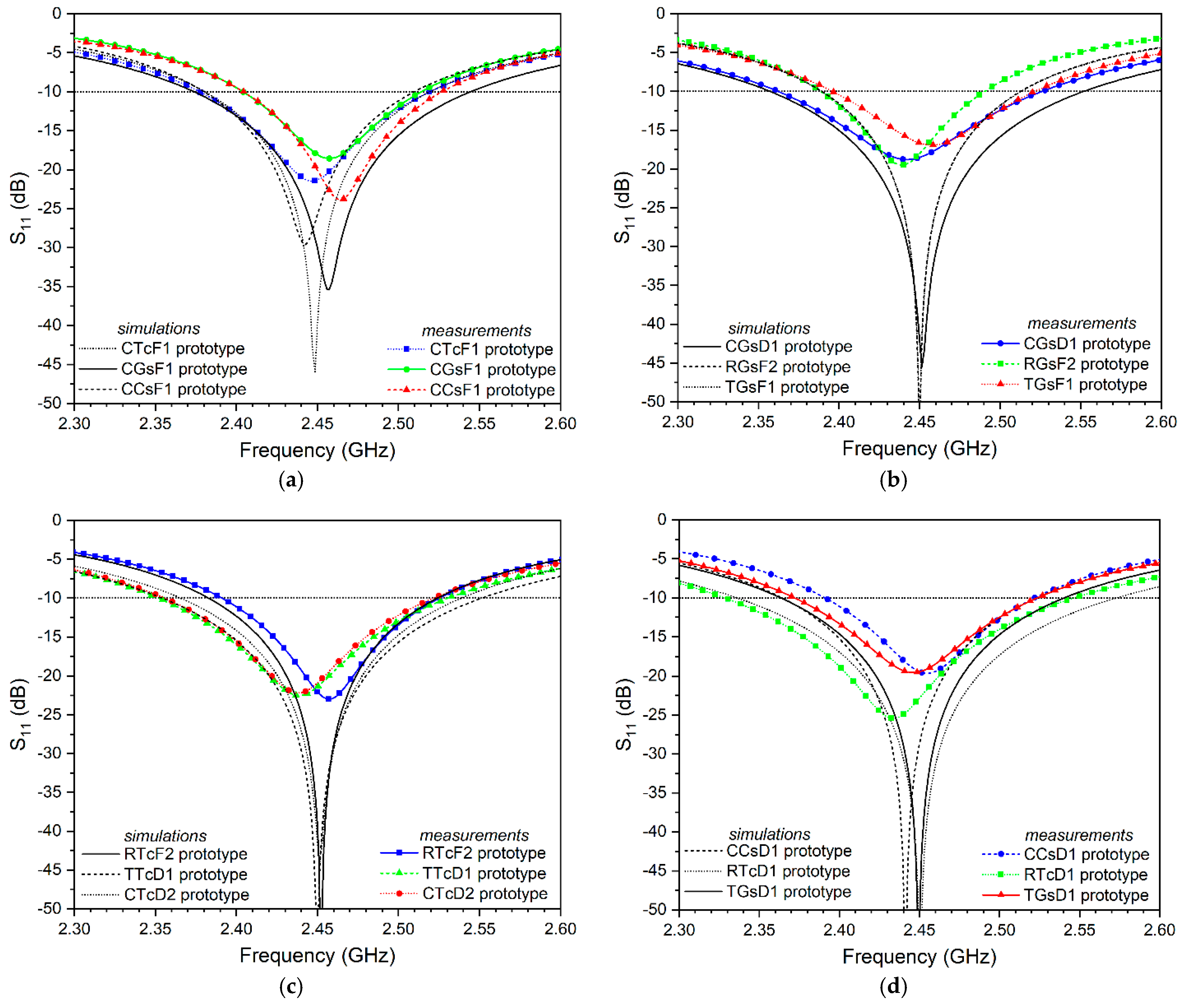
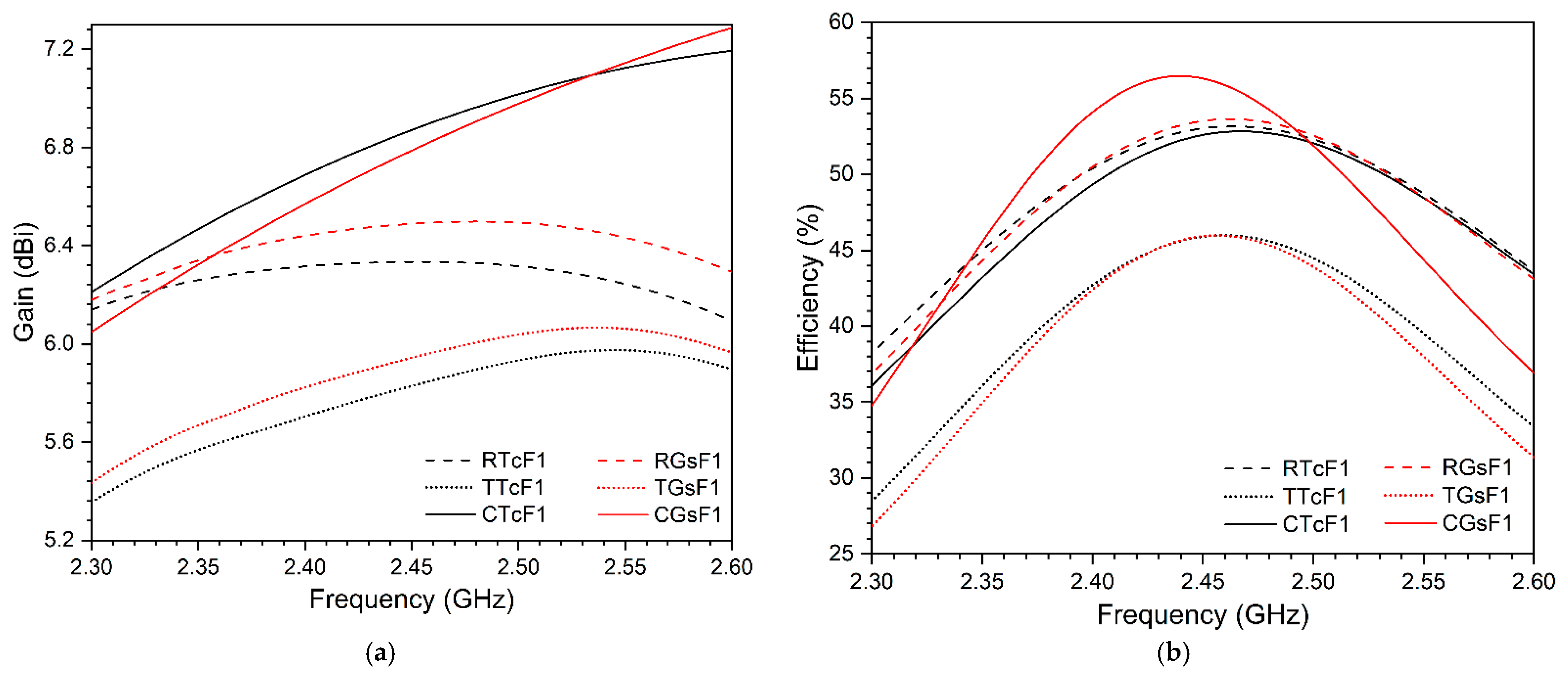
3.1. Simulation and Experimental Results for the Antennas in Free Space

Multiple simulation and experimental tests have been implemented, in order to evaluate the patch antenna performance and its dependence on the patch material, patch shape, and substrate material. Simulations were accomplished with the CST Studio Suite 2021 software package, whereas measurements were performed using an HP 8714ET RF network analyzer.
Indoor measurements in free space, under the usual environmental conditions for temperature (19 °C) and humidity (67%), were performed for all 36 prototypes. In Table 2, we have selected two rectangular (the conductive fabric RTcF1 and the graphene sheet RGsF1), two triangular (the conductive fabrics TTcD1 and TTcF1, the graphene sheet TGsD1, and the copper sheet TCsD2), and six circular (the conductive fabrics CTcF1 and CTcF2, the graphene sheets CGsD1 and CGsF1, and the copper sheets CCsD1 and CCsF1) representative prototypes to present their simulation results, in comparison to their corresponding measured characteristics. The first three lines of Table 2 contain the simulated and measured values of the resonant frequency fc, the scattering parameter S11 at fc, and the voltage standing wave ratio (VSWR) at fc, respectively. The next two lines include the simulated and measured values of the lower limit f1 and the upper limit f2 of the −10 dB bandwidth (BW), while the last 2 lines present the −10 dB BW in MHz and as a percentage of fc.
The measured and simulated reflection coefficient (S11 magnitude) is plotted in Figure 7 for: (a) the three circular CTcF1, CGsF1, and CCsF1 prototypes with the same felt F1 substrate but different patch materials; (b) the three graphene patch CGsD1, RGsF2, and TGsF1 prototypes with different substrate materials and patch shapes; (c) the three fabric-patch RTcF2, TTcD1, and CTcD2 prototypes with different substrate materials and patch shapes; and (d) the three denim D1 substrate CCsD1, RTcD1, and TGsD1 prototypes with different patch materials and patch shapes.
Table 2 and Figure 7 reveal that all antennas under study fully cover the unlicensed 2.4–2.5 GHz ISM band, having resonant frequencies that are not more than 1% away from the expected 2.45 GHz, although the prototypes’ performance may vary, based on their geometrical and fabrication characteristics. The measurements confirm the simulations and accuracy of the fabrication procedure, while the simulated results are better than the measured ones, in all cases. For example, the deviation between the simulated and measured values of the resonant frequency (fc), the lower-band limit (f1), and the upper-band limit (f2) were less than 1%, 1.6%, and 2.5%, respectively, for all prototypes. The difference between the simulated and measured bandwidth, less than 18.3% for all prototypes, is also acceptable. On the other hand, the considerable differences between the simulated and measured S11 and VSWR were anticipated, due to the practical limitation of the actual free space measurements of S11 @ fc to a minimum analyzer reading of almost −35 dB. In all cases, the use of graphene sheet for the patch is at least as effective as the use of copper sheet or conductive fabric.
Regarding the scattering parameter, the simulated values of S11 @ fc and the VSWR @ fc for the antennas under study varied between −61.1 dB and 1.002 (for CCsD1) and −29.6 dB and 1.068 (for CGsF1), while their measured values varied between −23.85 dB and 1.1371 (for CCsF1) and −18.06 dB and 1.2856 (for TCsD2). Table 2 does not reveal any obvious effect of the patch shape, patch material, or substrate material on S11 and VSWR.
The simulated −10 dB BW varied between 131 MHz (for CGsF1) and 197 MHz (for TTcD1), while the corresponding measured BW varied between 109 MHz and 178 MHz. The graphene sheet CGsD1 prototype has an excellent BW performance, comparable to that of the TTcD1 one, attributed to the thick denim D1 substrate, which is thinner (1.0 mm) than the felt F1 (3.0 mm) and F2 (1.5 mm) substrates, but it has considerably higher dielectric constant (1.63, in comparison to 1.13 and 1.34, respectively). A look at the graphene sheet patch antennas CGsD1, TGsD1, RGsF1, and CGsF1 (with simulated/measured BW 195/162 MHz, 178/150 MHz, 159/154 MHz, and 131/109 MHz, respectively), conductive fabric patch antennas TTcD1, RTcF1, CTcF1, CTcF2, and TTcF1 (with simulated/measured BW 197/178 MHz, 177/167 MHz, 171/140 MHz, 145/127 MHz, and 136/121 MHz), and copper sheet patch antennas CCsD1, TCsD2, and CCsF1 (with simulated/measured BW 159/130 MHz, 150/127 MHz, and 139/121 MHz) (Table 2 and Figure 7) confirms the positive effect of the substrate’s dielectric constant and thickness on bandwidth.

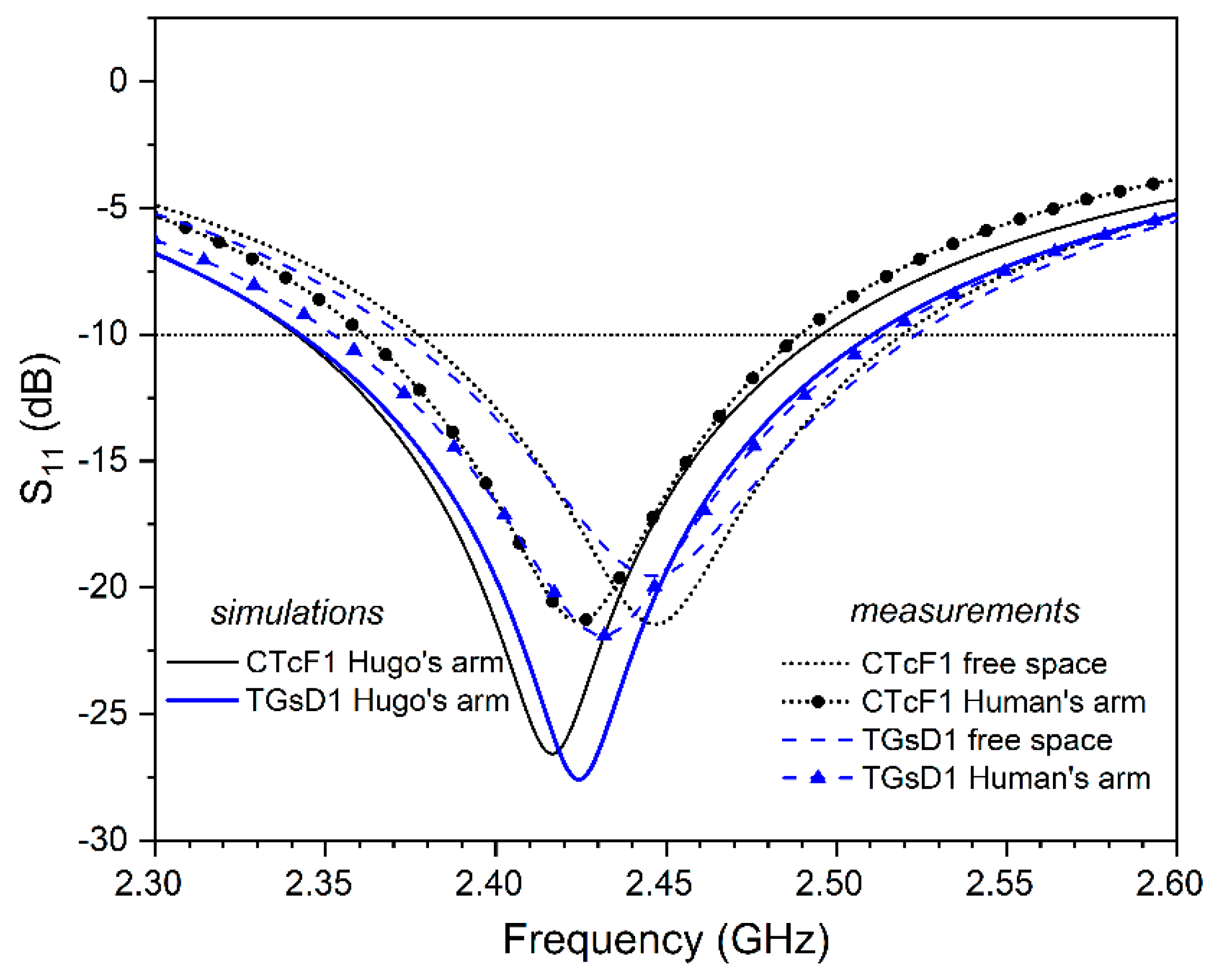
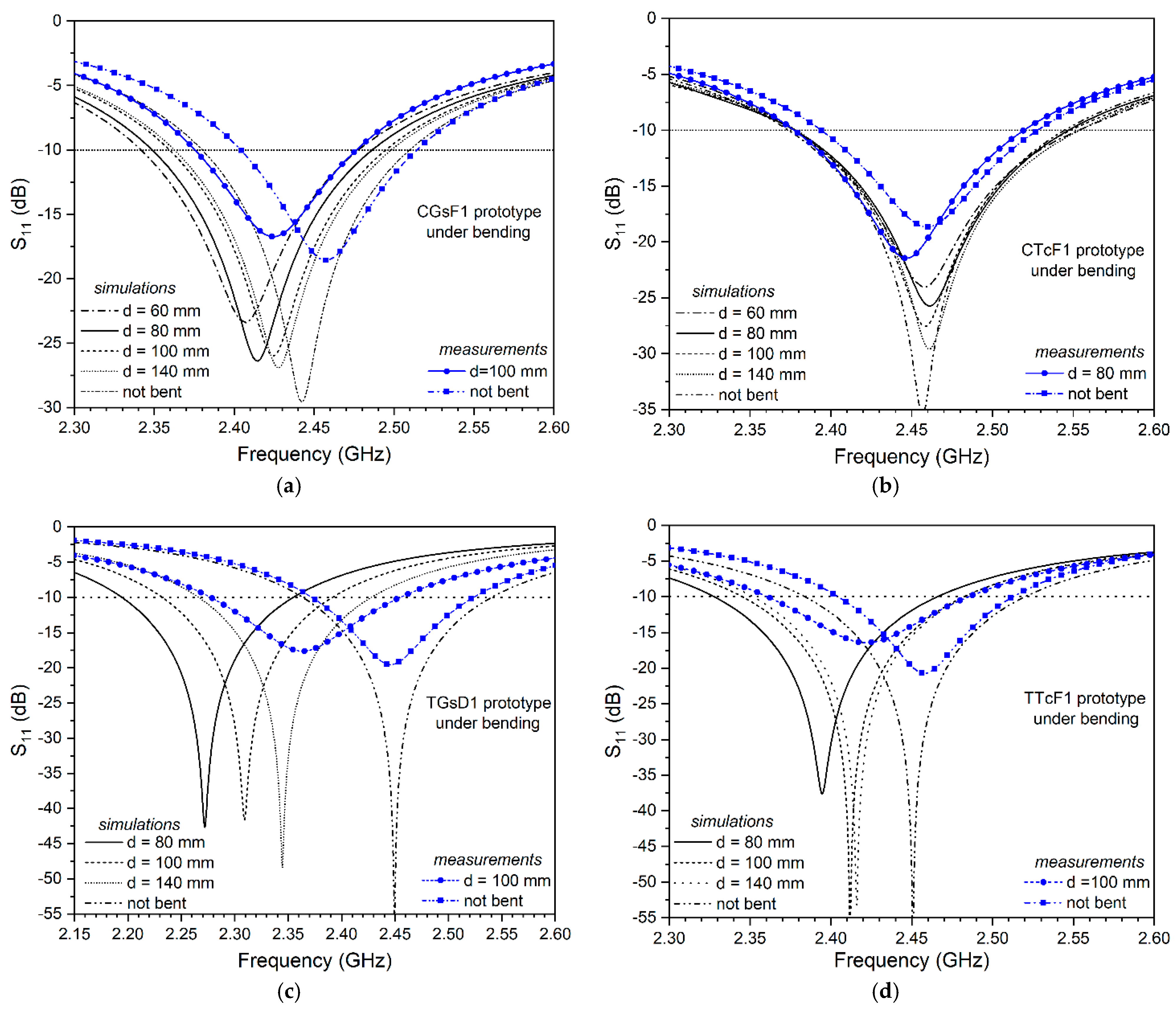
3.2. Results for the Antennas under Bending

Figure 8 shows our textile antenna geometries bending along their x- and y-axes over circular, cylindrical PVC tubes. The prototypes’ backsides are mounted on four different non-conductive tubes, with length 50 cm, dielectric constant εr = 4, diameters d = 60, 80, 100, and 140 mm, and thicknesses 2, 2, 3, and 4 mm, respectively. For brevity, we have chosen 4 (2 circular versus 2 triangular and 2 graphene sheets versus 2 conductive fabrics) out of the total 36 prototypes, in order to plot their reflection coefficient (S11 magnitude) versus frequency when the antennas are bent in the convex way, along each x-axis, as displayed in Figure 8. Figure 9a–d refers to the circular graphene sheet patch and felt-F1 substrate (CGsF1), circular conductive fabric patch and felt-F1 substrate (CTcF1), triangular graphene sheet patch and denim-D1 substrate (TGsD1), and the triangular conductive fabric patch and felt-F1 substrate (TTcF1) prototypes, respectively. For visualization clearness, the number of curves for S11 (dB), in each of Figure 9a–d, is confined to: (i) three or four curves without markers for the simulation results, in case of antenna bending over different tubes; (ii) one curve with markers for the corresponding measurement results, in case of antenna bending over only one of the previous tubes; and (iii) two additional curves for the simulation and measurement results, in case of the not-bent antenna in free space, included for comparison and reference.
According to Figure 9, the resonant frequency (fc) of the bent antenna decreases almost monotonically as the tube diameter also decreases. This characteristic behavior is more obvious for the graphene sheet patch antennas, in comparison to the conductive fabric patch ones, as well as for the triangular patch antennas, in comparison to the circular patch ones. For example, the simulated fc of the TGsD1 (TTcF1) prototype in Figure 9c,d was 2.45 (2.45) GHz for the not-bent case, and 2.345, 2.309, and 2.272 (2.416, 2.412, and 2.395) GHz for bending over a tube with diameters of 140, 100, and 80 mm, respectively, while the simulated fc of the CGsF1 (CTcF1) prototype in Figure 9a,b was 2.443 (2.457) GHz for the not-bent case, and 2.428, 2.425, 2.415, and 2.407 (2.461, 2.459, 2.460, and 2.458) GHz for bending over a tube with diameters of 140, 100, 80, and 60 mm, respectively. The same behavior also holds true for the measured resonant frequency, as the measured fc of the TGsD1 (TTcF1) prototype in Figure 9c,d was 2.446 (2.461) GHz for the not-bent case and 2.365 (2.423) GHz for bending over a tube with a diameter of 100 (100) mm; while the measured fc of the CGsF1 (CTcF1) prototype in Figure 9a,b was 2.457 (2.460) GHz for the not-bent case and 2.424 (2.447) GHz for bending over a tube with a diameter of 100 (80) mm.
Regarding the width of the −10 dB BW under bending, the simulated BW of the triangular patch TGsD1 (TTcF1) prototype in Figure 9c,d decreased by 18 MHz (increased by 26 MHz), from 178 (136) MHz for the not-bent case, to almost 160 (162) MHz for all bending conditions, while the simulated BW of the circular patch CTcF1 (CGsF1) prototype in Figure 9a,b slightly increased by 3 MHz (increases by 6 MHz), from 171 (128) MHz for the not-bent case to almost 173 (134) MHz for all bending conditions. The measured bandwidth confirms this behavior, as the measured BW of the triangular patch TGsD1 (TTcF1) prototype in Figure 9c,d slightly increased by 2 MHz, from 166 (123) MHz for the not-bent case to 168 (125) MHz under bending, while the measured BW of the circular patch CTcF1 (CGsF1) prototype in Figure 9a,b increased by 10 MHz (decreased by 7 MHz), from 134 (110) MHz for the not-bent case to 143 (103) MHz under bending. Therefore, the circular and conductive fabric patch antennas exhibit better under-bending performance than the triangular and the graphene sheet patch ones, respectively.
Despite the adequate measured (simulated) bent antennas’ bandwidth, ranging from 103 (134) MHz to 168 (174) MHz for all prototypes and bending conditions, the above-mentioned shift of fc, along with the BW decrement, affected antenna operation under bending, only partially covering the 2.4–2.5 GHz ISM band, in most cases, except for those with circular conductive fabric patches. For example, the measured useful BW of the bent TTsF1, TGsD1, and CGsF1 prototypes is 2.29–2.43, 2.29–2.46, and 2.38–2.48 GHz, respectively; although, the CTcF1 antenna exhibited excellent under-bending behavior (shown in Figure 9b by retaining its measured useful BW to 2.38–2.52 GHz and, thus, covering the ISM band). This remark applies to all prototypes and bending conditions tested, although the full set of simulated and measured results is not presented here for brevity.
Consequently, the circular conducting fabric patch CTcF1 and the triangular graphene sheet patch TGsD1 antenna prototypes were mounted on a human arm, in order to investigate the effect of human body presence. The measured and simulated reflection coefficient (S11) is plotted in Figure 10, when the prototypes are either: (i) in free space (measurements); (ii) body-mounted on the arm of the complex, multi-layered, anatomical, full-body, voxel model, named Hugo [56] (simulations); or (iii) body-mounted on the arm of one of the authors (measurements). The bulleted curves correspond to the measured results, in case of antenna natural bending on a human arm, when the prototype’s backside is in touch with a t-shirt’s sleeve, whereas the solid curves represent simulated results, in case of the prototype’s presence beside CST-Hugo’s arm. Measured results, when each prototype was in free space (dashed or dotted curve), are inserted in Figure 10 for reference. Figure 10 reveals a down-shift of the resonant frequency from the measured 2.447 GHz (2.446 GHz) for the CTcF1 (TGsD1) prototype in free space, 2.424 GHz (2.43 GHz) for the human-mounted antenna, as well as the simulated 2.423 GHz (2.426 GHz) for the Hugo-mounted antenna. At the same time the bandwidth increased considerably from the measured 150 ΜHz for the TGsD1 prototype in free space, 162 ΜHz for the human-mounted antenna, and the simulated 168 ΜHz for the Hugo-mounted antenna. Nevertheless, the ISM band was fully covered, in all cases, which is very promising for the actual wearability of the antennas proposed herein.
At this point, it is noteworthy that the significant advantages of the wearable textile patch antennas, mentioned in the Introduction, are also valid for all antenna prototypes proposed in this paper, even though, during the design and fabrication procedures, we encountered some possible, slight drawbacks, such as: (i) the non-flexible connection between the antenna and the transmitter/receiver module, due to the SMA connector, (ii) low performance of the triangular patch antenna prototypes under bending conditions, (iii) lack of accurate simulation models for fabric substrates (which affects the antenna characteristics), (iv) uncertainties of the simulation models for complex conductive patch materials, and (v) expected demand for computational resources.

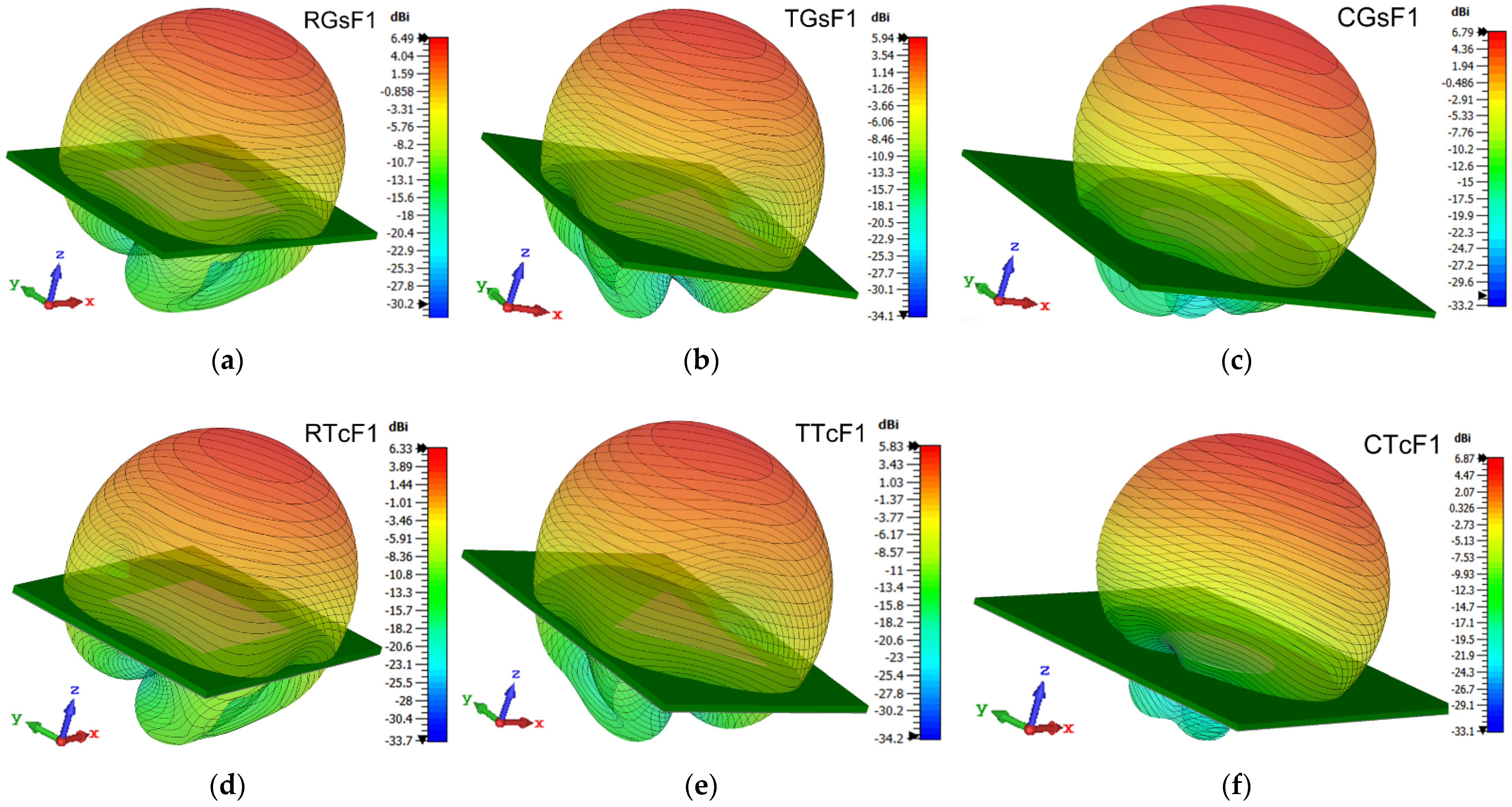
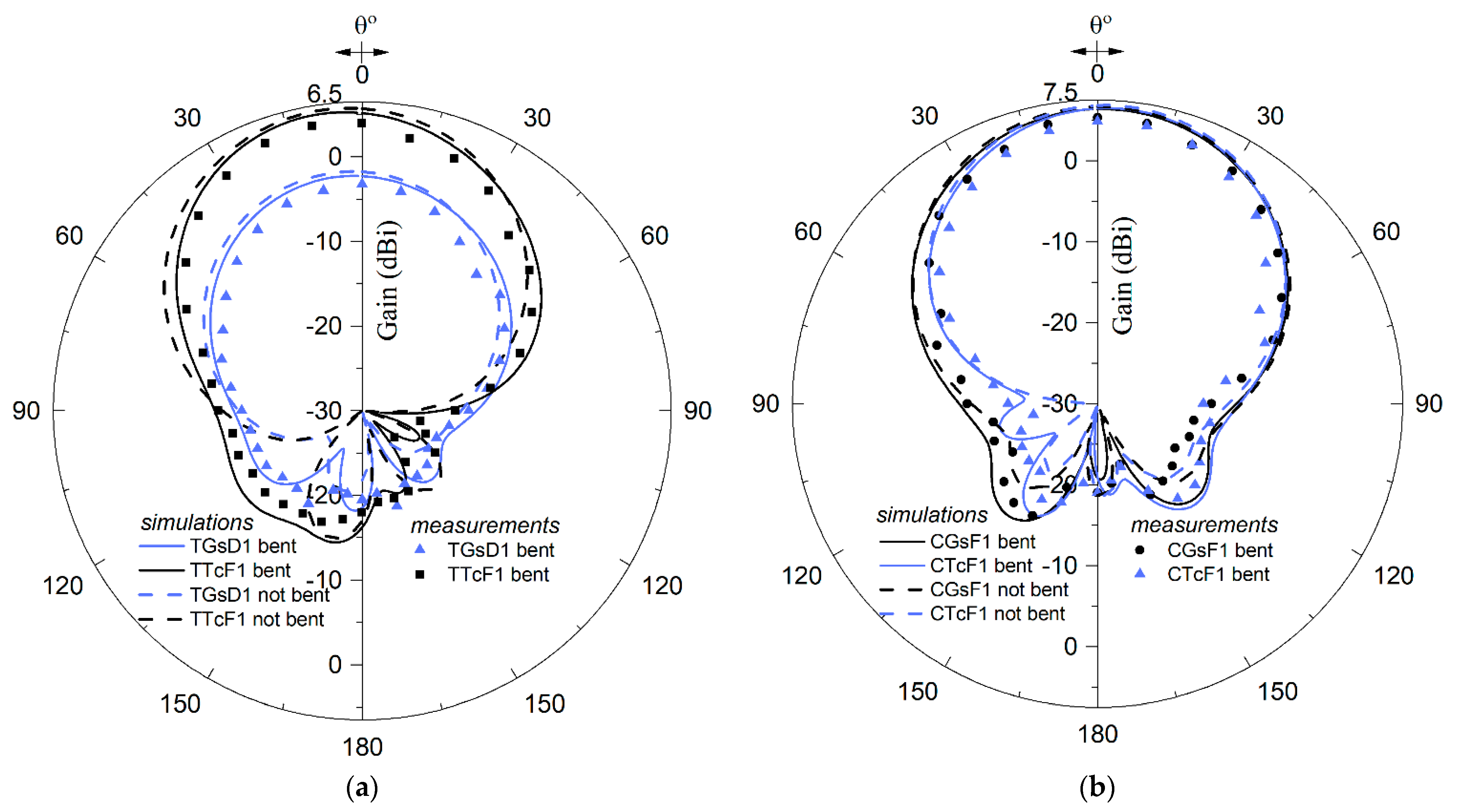
3.3. Radiation Characteristics
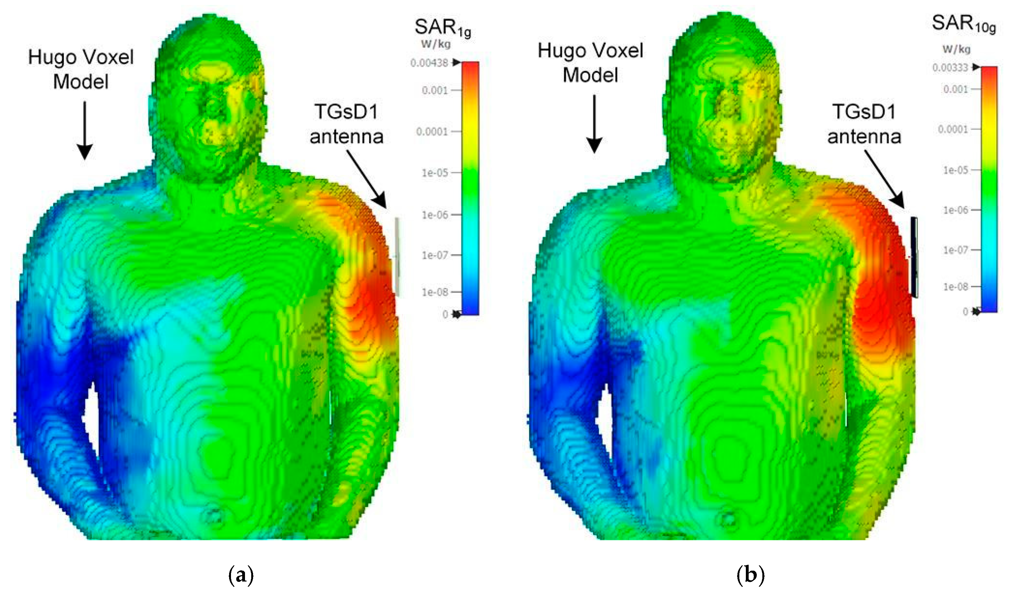
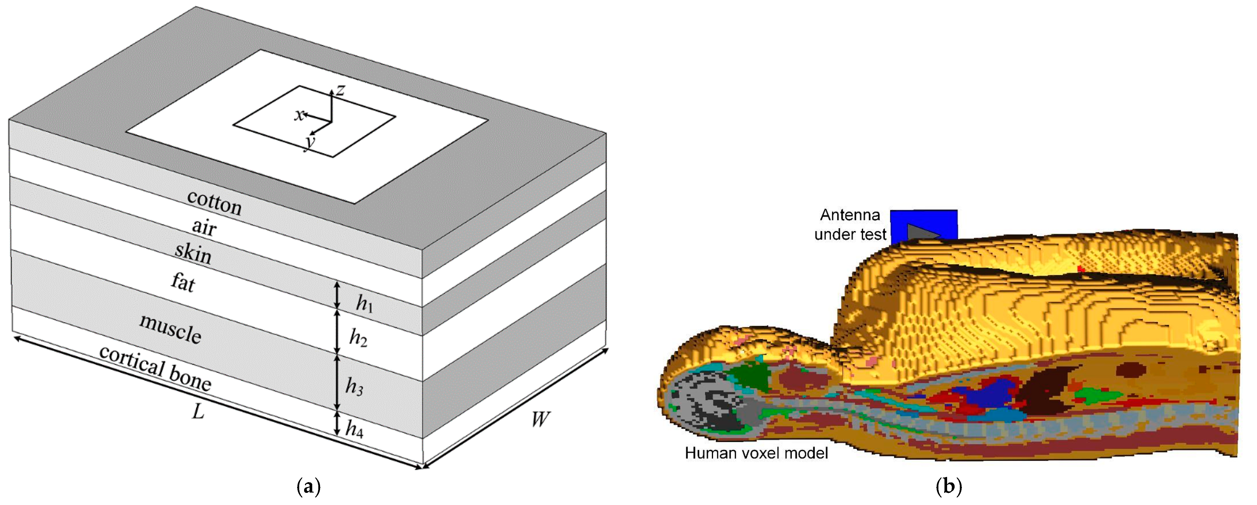
The radiation patterns and characteristics of all prototypes were simulated with the CST Studio Suite 2021 software and measured with the MegiQ RMS-0660 radiation measurement system. The measurements took place using the direct method, having an ±1 dB uncertainty, according to the manufacturer. Figure 11 presents a picture of the measurement setup at work.
Figure 12 shows representative results for the θ-plane (elevation plane or E-plane) radiation patterns of 12 different prototypes. The dotted, dashed, and solid curves illustrate the simulated results, whereas the circles, squares, and triangles present the corresponding measured E-plane radiation patterns of the patch antennas, mentioned for each inset. At the same time, Figure 13 presents the 3D radiation patterns of six different prototypes with the same F1 substrate. All patterns of Figure 12 and Figure 13 are plotted for the corresponding prototypes’ resonant frequencies, which are shown at the first two rows of Table 2, for most cases, and given below. Moreover, the measurements for all antennas demonstrate a reasonable, and, in several cases, close agreement with the simulated results. The measured and simulated φ-plane (azimuthal plane or H-plane) radiation patterns, not shown in Figure 12, are omnidirectional and dipole-like, as expected [55]. This behavior was clearly revealed from the 3D radiation patterns of Figure 13, where the main lobe of each prototype fully covered the area above the patch antenna (for z > 0), while several low side lobes appeared below the antenna’s ground plane (for z < 0). The number and shape of the weak side lobes varied in each configuration, while the simulated gain of the strong main lobe as between 5.83 dBi (for the TTcF1) and 6.87 dBi (for the CTcF1). The circular prototypes (Figure 13c,f) exhibit better performance than the rectangular ones (Figure 13a,d), which, on their turn, perform better than the triangular antennas (Figure 13b,e). On the other hand, graphene (Figure 13a–c) and textile (Figure 13d–f) prototypes of the same geometry seem to have similar performance.
The patch shape, patch material, and the substrate material significantly affected the prototypes’ radiation characteristics. In Figure 12a, the comparison between the RTcD2 (@ 2.457 GHz), TGsD1 (@ 2.45 GHz), and CGsD1 (@ 2.451 GHz) prototypes revealed that the graphene patch antennas on denim substrates, and, especially, the CGsD1 of circular shape, have clearly better radiation performance, with higher gain and lower back-lobes, than the fabric patch prototypes, such as RTcD2. This remark seems to be partially reversed in Figure 12b,c, where the RGsF1 (@ 2.45 GHz), TTcF1 (@ 2.45 GHz), and CTcF1 (@ 2.457 GHz) prototypes, as well as the RGsF2 (@ 2.439 GHz), TTcF2 (@ 2.441 GHz), and CTcF2 (@ 2.45 GHz) prototypes, respectively, are compared, because the fabric patch antennas on felt substrates, and, especially, the CTcF1 and CTcF2 of circular shape, seem to perform better with a slightly higher gain and definitely lower back-lobes than the graphene patch prototypes RGsF1 and RGsF2. However, according to several other radiation measurements (that are not shown in Figure 12), the pure performance of RGsF1 and RGsF2 was not due to the graphene patch, but to its rectangular shape, which was clearly disadvantageous, compared to the circular one. Finally, in Figure 12d, the comparison between the CGsF1 (@ 2.433 GHz), CCsF1 (@ 2.448 GHz), and CCsD1 (@ 2.441 GHz) prototypes reveals the radiation advantage of patch antennas with felt F1 substrate (with hs = 3.0 mm, εr = 1.13, and tanδ = 0.041) over those with denim D1 substrate (with hs = 1.0 mm, εr = 1.63, and tanδ = 0.086), due to F1′s lower losses and dielectric constant, regardless of its thickness. It is worth mentioning that circular graphene sheet and copper sheet patches of the same substrate have almost identical radiation responses, confirming our last remark of the excellent suitability of graphene for wearable antenna applications.
The simulated gain, directivity, and efficiency of all the 36 under-study antennas, are given in Table 3. The simulated efficiency of the fabricated prototypes was varied from 5.0% (for TGsD2) to 57.1% (for CCsF1), which is rather reasonable. Regarding the antenna efficiency, the substrate material was the determining factor, while the patch material and shape had a relatively small effect. This behavior was expected, because the loss of the substrate, due to its size, played a very crucial role, as lower-loss substrates (as the felt F1) resulted in higher efficiencies, and higher-loss substrates (as the denim D2) led to significantly lower efficiencies. If we classify the four substrate materials used in this work in ascending order, according to their combination of dielectric constants (εr) and loss tangent (tanδ), we firstly had the felts F1 (1.13 and 0.041) and F2 (1.34 and 0.039) and, lastly, the denims D1 (1.63 and 0.086) and D2 (1.81 and 0.073). Consequently, the higher values of efficiency in Table 3 were met in antennas with the felt F1 substrate, namely the CCsF1 (57.1%), RCsF1 (56.7%), CGsF1 (56.0%), RGsF1 (53.5%), RTcF1 (53.0%), CTcF1 (52.6%), TCsF1 (49.5%), TGsF1 (45.9%), and TTcF1 (45.9%) prototypes.
On the contrary, the lower values of efficiency in Table 3 were met in antennas with the denim D2 (or D1 for circular geometries) substrate, namely the TGsD2 (5.0%), TTcD2 (5.2%), TCsD2 (5.5%), RGsD2 (6.7%), RCsD2 (8.0%), RTcD2 (8.5%), CTcD2 (11.3%), CGsD1 (13.0%), CTcD1 (13.6%), CCsD1 (14.7%), CCsD2 (16.1%), and CGsD2 (25.3%) prototypes. As observed, for the same substrate material, the circular patch antennas were preferable to the rectangular, and, especially, the triangular ones, while the graphene patch antennas were slightly better than the fabric ones and almost as good as the copper ones.
In the last row of each of the three parts of Table 3, the simulated and measured results for antenna gain were depicted for comparison. The latter were significantly lower than their corresponding simulated values, since real losses are always superior to the simulated ones.
Figure 14 presents the indicative results for the θ-plane radiation patterns of four different prototypes, bent over a tube, with diameters of 100 mm. The dashed and solid curves illustrate the simulated results, whereas the symbols present the corresponding measured E-plane radiation patterns of the bent patch antennas, mentioned for each inset. The simulated results, when the prototypes were not bent in free space (dashed curves), were inserted in Figure 14 for reference. A satisfactory agreement is, once again, observed between the measured and the simulated results, while bending does not seem to have significant effect on the main lobe of the radiation pattern, once again, proving the actual wearability of the antennas proposed herein.
The 2D plots of the simulated gain (dBi) and efficiency (%) are shown in Figure 15 for three graphene sheets (rectangular RGsF1, triangular TGsF1, and circular CGsF1) and three conductive textile (rectangular RTcF1, triangular TTcF1, and circular CTcF1) prototypes. Since all six prototypes of Figure 15 have the same F1 substrate, comparisons between antennas of different geometrical shapes and/or patch materials can be made. The superiority of (i) circular (solid lines) over rectangular (dashed lines) and triangular (dotted lines) prototypes, as well as (ii) graphene patch (red-colored lines) over textile patch (black-colored lines) antennas, is obvious in almost all cases. As depicted in Figure 15a (Figure 15b), the radiation gain (efficiency) of the graphene sheet RGsF1 and TGsF1 (CGsF1) prototypes exceeds the gain (efficiency) of the corresponding conductive textile RTcF1 and TTcF1 (CTcF1) prototypes over the 2.4–2.5 GHz operating frequency band. Figure 15a reveals that the gain of the circular (triangular) prototypes increases considerably (slightly) with increasing frequency, while, at the same time, the gain of the rectangular prototypes is rather stable or tending to decrease. On the other hand, Figure 15b demonstrates that in all cases the efficiency reaches its peak value (between 45.9% for the TGsF1 and 56% for the CGsF1) at the resonant frequency.

3.4. SAR Εvaluation

Due to the proximity of the proposed wearable patch antennas to the human body (and especially to the human chest and arm), the produced Specific Absorption Rate (SAR), which is the key radiation exposure parameter, has to be evaluated, studied, and compared to the regulating electromagnetic radiation exposure limits provided by the national authorities and the IEEE Standards [63,64]. For the general public, the SAR limits set by international standards and apply in USA and EU are: 0.08 W/kg for the whole-body max SAR, 1.6 W/Kg for the peak SAR averaged per 1 g of radiated tissue, and 2 W/kg for the peak SAR averaged in a volume of 10 g tissue.
Figure 16 illustrates the simplified rectangular four-layered human chest model [11,53] and the complex multi-layered anatomical full body voxel model named Hugo [56] used in this paper for SAR calculations. Both simulation models are useful. On one hand, the simplified rectangular chest model, due to its low complexity, has limited demands in computational time and resources and can be easily modified concerning the number, the thicknesses and the material properties of the tissue layers, leading to decent estimates. On the other hand, the anatomical voxel model, due to its high complexity and close similarity to real human body’s anatomical structure, demands much more computational resources and time, ensuring high accuracy results.
The electrical characteristics (conductivity σ, dielectric constant εr and loss tangent tanδ, calculated @ 2.45 GHz using widely known approximations [65,66]), the densities and the thicknesses of the four human tissue layers that compose the simplified chest model are given in Table 4. A 1.5 mm thick cotton (εr = 1.6, tanδ = 0) t-shirt along with an 1 mm air (εr = 1, tanδ = 0) gap, in case of Figure 16a, or just an 2.5 mm air gap in case of Figure 16b, are considered to separate the human skin from the antenna.
One after the other all the antenna prototypes are positioned at the top center of the simplified rectangular chest model, as shown in Figure 16a, or in the vicinity of Hugo’s left arm model, as shown in Figure 16b, and they are fed with 0.5 W rms input power. All simulations are executed for the 2.45 GHz central frequency of the ISM band and the whole-body max SAR and the average SAR in a volume of 1 g and 10 g tissue are calculated according to the relevant international regulations and standards [63,64]. The SAR results from both (the simplified and the voxel) models for 12 antenna prototypes are presented in Table 5. The prototypes are sorted in ascending order of the value of the peak SAR averaged in a volume of 10 g tissue, shown in the first row of Table 5. The lower value of the simplified model’s peak 10 g SAR is 0.001 W/Kg, corresponding to the CGsD2 and CCsF2 prototypes, while its higher value is 0.034 W/Kg, corresponding to the RCsF2 prototype. At the same time, the higher values of the simplified model’s peak 1 g SAR, the voxel model’s peak 1 g SAR, and the voxel model’s peak 10 g SAR are 0.06, 0.056, and 0.033 W/Kg, respectively, for the RTcF1 prototype. Moreover, the values of the max whole-body SAR for all prototypes under study, not shown in Table 5, are between 5.43 × 10⁻⁴ and 4.98 × 10⁻³ W/Kg.
All the computed SAR values are far below the aforementioned limits. Even in the worst-case scenario when the antenna is placed directly on the human body model and there is no air gap, the SAR values increase imperceptibly, being always much lower than the limits.
Figure 17 illustrates the SAR distribution on CST-Hugo’s voxel model, due to the radiation of the TGsD1 prototype. The SAR values are maximum in the left arm area near the antenna location and are rapidly diminishing as the distance from the antenna increases. The SAR values do not exceed the general public regulation levels in any case and in fact, as depicted in Figure 17 and Table 5, are very low for all the patch antenna prototypes, because of the inherent presence (on the opposite side of the patch) of a ground-plane layer facing the human body.

3.5. Comparisons

Finally, Table 6 compares the fabrication characteristics and the antenna performances of the herein proposed graphene sheet and conductive fabric patch prototypes, with related published works [23,43,45,47,51,52,59,67,68,69,70,71]. Refs. [23,47,51,52,59,71] present antennas operating in the same frequency band as the prototypes under study, while [43,45,67,68,69,70] refer to different operating frequencies, making cautiousness necessary before any direct comparisons and drawn conclusions.
The antennas reported in [23,47,51,52,59,71] exhibit: (i) −10 dB BW in the range 42–213 MHz, which is comparable to the bandwidth (121–178 MHz) of our prototypes, (ii) VSWR in the range 1.01–1.785, which is analogous to the ratio (1.16–1.24) of our prototypes, (iii) gain in the range 0.7–7.1 dBi, which is similar to the gain (−5.89–5.98 dBi) for several of our prototypes, (iv) efficiency in the range 29.1–85.0%, which is generally higher than the efficiency (5.0–56.0%) of our prototypes, and (v) peak SAR averaged over 10 g of tissue in the range 0.11–0.97, which is considerably higher than the SAR (0.002–0.011) of all our prototypes. Consequently, the antennas under study seem to have a definite advantage in terms of very low SAR, and a possible disadvantage regarding their efficiency in several cases, although a nominal efficiency of about 50% is reasonably acceptable for hand-made patch antennas with simple geometry and low fabrication complexity. For example, in [23] the excellent efficiency value of 85% may be attributed to the microwave foam substrate, which we are going to investigate in a future work, while in [71] the very good efficiency value of 78% can be justified by its modified rectangular shape. The impressive ultra-broad bandwidth of 3000 MHz in [69], despite its different operation frequency, may be attributed to its special quasi-Yagi–Uda antenna (unlike the herein classical types and shapes), its kapton substrate (in contrast with our every-day fabric substrates), and its high fabrication complexity (against the herein procedure).

4. Conclusions

Textile rectangular, triangular, and circular probe-fed patch antennas, which may be easily attached to clothing, have been presented in this paper for operation in the free 2.45 GHz ISM band. Thirty-six different wearable prototypes have been optimized, designed, simulated, fabricated, measured, compared, and presented. Patches from three different conductive materials (graphene sheet, conductive fabric, and copper sheet) have been pasted on substrates from four different textiles (thin and thick denim, thin and thick felt) using an ultra-thin thermoplastic adhesive layer.
Extensive simulations and measurements have been performed to evaluate the prototypes’ performance. The proposed antennas, despite their classical simple geometries, manage to fully cover the ISM band. The comparative study of graphene textile, all textile, and copper textile antennas reveal the excellent suitability of graphene for wearable applications.
The fabricated prototypes are characterized by their flexibility, light weight, mechanical stability, resistance to shock, bending and vibrations, unhindered integration to clothes, low-cost implementation, simple and industry compatible fabrication process, and very low SAR values. Additionally, the graphene sheet patch prototypes are resistant to corrosion, while the circular ones have very good performance under bending conditions.
Most prototypes present satisfactory performance, and some achieve very good characteristics. For example, the circular graphene patch felt substrate CGsF1 prototype accomplishes 109 MHz measured bandwidth, 5.45 dBi gain, 56% efficiency, and excellent performance under bending. According to SAR simulations with 2 different body models, all antennas are far below the exposure limits and, thus, can be used for wearable IoT applications. Antennas ageing properties, their operation under moisture, and their real time performance when embedded in IoT nodes will be investigated in a future work.

Author Contributions

Conceptualization, T.N.K. and I.O.V.; methodology, T.N.K. and I.O.V.; software, C.D.N.; validation, T.N.K., C.D.N., and I.O.V.; formal analysis, K.P. and I.O.V.; measurements, T.N.K. and C.D.N.; investigation, T.N.K., C.D.N., K.P., and I.O.V.; resources, C.D.N., T.N.K. and I.O.V.; data curation, C.D.N. and T.N.K.; writing—original draft preparation, T.N.K., K.P. and I.O.V.; writing—review and editing, T.N.K. and I.O.V.; visualization, C.D.N. and T.N.K.; supervision, I.O.V.; project administration, K.P. and I.O.V.; funding acquisition, T.N.K., K.P, C.D.N., and I.O.V. All authors have read and agreed to the published version of the manuscript.

Funding

This research is co-financed by Greece and the European Union (European Social Fund—ESF) through the Operational Program “Human Resources Development, Education and Lifelong Learning 2014–2020” in the context of the project “Smart microwave nanomaterial structures with applications in bodycentric communications and the Internet of Things (MIS 5048187)”.

Data Availability Statement

The data presented in this study are available on request from the corresponding author. The data were not publicly available, due to privacy restrictions.

Conflicts of Interest

The authors declare no conflict of interest.

References

  1. Hall, P.; Hao, Y. Antennas and Radio Propagation for Body-Centric Wireless Communications; Artech House: London, UK, 2006. [Google Scholar]
  2. Moradi, E.; Koski, K.; Bjorninen, T.; Sydanheimo, L.; Rabaey, J.M.; Carmena, J.M.; Rahmat-Samii, Y.; Ukkonen, L. Miniature implantable and wearable on-body antennas: Towards the new era of wireless body-centric systems. IEEE Antennas Propag. Mag. 2014, 56, 271–291. [Google Scholar]
  3. Sun, H.; Hu, Y.; Ren, R.; Zhao, L.; Li, F. Design of pattern-reconfigurable wearable antennas for body-centric communications. IEEE Antennas Wirel. Propag. Lett. 2020, 19, 1385–1389. [Google Scholar] [CrossRef]
  4. Kirtania, S.G.; Elger, A.W.; Hasan, R.; Wisniewska, A.; Sekhar, K.; Karacolak, T.; Sekhar, P.K. Flexible antennas: A review. Micromachines 2020, 11, 847. [Google Scholar] [CrossRef] [PubMed]
  5. Loss, C.; Goncalves, R.; Lopes, C.; Pinho, P.; Salvado, R. Smart coat with a fully-embedded textile antenna for IoT applications. Sensors 2016, 16, 938. [Google Scholar] [CrossRef] [PubMed]
  6. Almohammed, B.; Ismail, A.; Sali, A. Electro-textile wearable antennas in wireless body area networks: Materials, antenna design, manufacturing techniques, and human body consideration-A review. Text. Res. J. 2021, 91, 646–663. [Google Scholar] [CrossRef]
  7. Khaleel, H. Innovation in Wearable and Flexible Antennas; WIT Press: Hampshire, UK, 2015. [Google Scholar]
  8. Lilja, J.; Salonen, P.; Kaija, T.; de Maagt, P. Design and manufacturing of robust textile antennas for harsh environments. IEEE Trans. Antennas Propagat. 2012, 60, 4130–4140. [Google Scholar] [CrossRef]
  9. Salvado, R.; Loss, C.; Concalves, R.; Pinho, P. Textile materials for the design of wearable antennas: A survey. Sensors 2012, 12, 15841–15857. [Google Scholar] [CrossRef] [PubMed]
  10. Pavec, M.; Kapetanakis, T.N.; Ioannidou, M.P.; Nikolopoulos, C.D.; Baklezos, A.T.; Soukup, R.; Blecha, T.; Hamacek, A.; Vardiambasis, I.O. Implementation of an all-textile bow-tie antenna for the 868 MHz ISM band. In Proceedings of the 2020 International Symposium on Electromagnetic Compatibility (EMC Europe 2020), Rome, Italy, 23–25 September 2020. [Google Scholar]
  11. Kapetanakis, T.N.; Pavec, M.; Ioannidou, M.P.; Nikolopoulos, C.D.; Baklezos, A.T.; Soukup, R.; Vardiambasis, I.O. Embroidered bow-tie wearable antenna for the 868 and 915 MHz ISM bands. Electronics 2021, 10, 1983. [Google Scholar] [CrossRef]
  12. Kiourti, A.; Lee, C.; Volakis, J.L. Fabrication of textile antennas and circuits with 0.1mm precision. IEEE Antennas Wirel. Propag. Lett. 2016, 15, 151–153. [Google Scholar] [CrossRef]
  13. Tsolis, A.; Whittow, W.G.; Alexandridis, A.A.; Vardaxoglou, J.C. Embroidery and related manufacturing techniques for wearable antennas: Challenges and opportunities. Electronics 2014, 3, 314–338. [Google Scholar] [CrossRef] [Green Version]
  14. Zhong, J.; Lee, C.W.; Papantonis, D.; Kiourti, A.; Volakis, J.L. Body-worn 30:1 bandwidth tightly coupled dipole array on conductive textiles. IEEE Antennas Wirel. Propag Lett. 2018, 7, 723–726. [Google Scholar] [CrossRef]
  15. Kiourti, A.; Volakis, J.L. Colorful textile antennas integrated into embroidered logos. J. Sens. Actuator Netw. 2015, 4, 371–377. [Google Scholar] [CrossRef]
  16. Tak, J.; Choi, J. An all-textile Louis Vuitton logo antenna. IEEE Antennas Wirel. Propag. Lett. 2015, 14, 1211–1214. [Google Scholar] [CrossRef]
  17. Yadav, A.; Kumar Singh, V.; Kumar Bhoi, A.; Marques, G.; Garcia-Zapirain, B.; de la Torre Díez, I. Wireless body area networks: UWB wearable textile antenna for telemedicine and mobile health systems. Micromachines 2020, 11, 558. [Google Scholar] [CrossRef]
  18. Ahmed, M.I.; Ahmed, M.F.; Shaalan, A.-E.H. SAR calculations of novel textile dual-layer UWB lotus antenna for astronauts spacesuit. Prog. Electromagn. Res. C 2018, 82, 135–144. [Google Scholar] [CrossRef] [Green Version]
  19. Bharadwaj, R.; Swaisaenyakorn, S.; Parini, C.G.; Batchelor, J.C.; Alomainy, A. Impulse radio ultra-wideband communications for localization and tracking of human body and limbs movement for healthcare applications. IEEE Trans. Antennas Propagat. 2017, 65, 7298–7309. [Google Scholar] [CrossRef]
  20. Singh, V.K.; Dhupkariya, S.; Bangari, N. Wearable ultra wide dual band flexible textile antenna for WiMax/WLAN application. Wirel. Pers. Commun. 2017, 95, 1075–1086. [Google Scholar] [CrossRef]
  21. Gao, Y.; Zheng, Y.; Diao, S.; Toh, W.-D.; Ang, C.-W.; Je, M.; Heng, C.-H. Low-power ultrawideband wireless telemetry transceiver for medical sensor applications. IEEE Trans. Biomed. Eng. 2011, 58, 768–772. [Google Scholar] [CrossRef]
  22. Ziai, M.A.; Batchelor, J.C. Temporary on-skin passive UHF RFID transfer tag. IEEE Trans. Antennas Propagat. 2011, 59, 3565–3571. [Google Scholar] [CrossRef]
  23. Liu, F.X.; Xu, Z.; Ranasinghe, D.C.; Fumeaux, C. Textile folded half-mode substrate-integrated cavity antenna. IEEE Antennas Wirel. Propagat. Lett. 2016, 15, 1693–1697. [Google Scholar] [CrossRef]
  24. Hong, Y.; Tak, J.; Choi, J. An all-textile SIW cavity-backed circular ring-slot antenna for WBAN applications. IEEE Antennas Wirel. Propagat. Lett. 2016, 15, 1995–1999. [Google Scholar] [CrossRef]
  25. Amendola, S.; Bovesecchi, G.; Palombi, A.; Coppa, P.; Marrocco, G. Design, calibration and experimentation of an epidermal RFID sensor for remote temperature monitoring. IEEE Sens. J. 2016, 16, 7250–7257. [Google Scholar] [CrossRef]
  26. Islam, M.; Alam, T.; Yahya, I.; Cho, M. Flexible radio-frequency identification (RFID) tag antenna for sensor applications. Sensors 2018, 18, 4212. [Google Scholar] [CrossRef] [Green Version]
  27. Maleky, O.E.; Abdelouahab, F.B.; Essaaidi, M.; Ali Ennasar, M. Design of simple printed dipole antenna on flexible substrate for UHF band. Procedia Manuf. 2018, 22, 428–435. [Google Scholar] [CrossRef]
  28. Moradi, B.; Fernandez-Garcia, R.; Gil, I. Wearable high-performance meander ring dipole antenna for electronic-textile applications. J. Text. Instit. 2020, 111, 178–182. [Google Scholar] [CrossRef]
  29. Sreemathy, R.; Hake, S.; Sulakhe, S.; Behera, S. Slit loaded textile microstrip antennas. IETE J. Res. 2020, 1–9. [Google Scholar] [CrossRef]
  30. Ansari, J.A.; Singh, P.; Yadav, N.P. Analysis of wideband multilayer patch antenna with two parasitic elements. Microw. Opt. Technol. Lett. 2009, 51, 1397–1401. [Google Scholar] [CrossRef]
  31. Abdelgwad, A.H. Microstrip patch antenna enhancement techniques. Int. J. Electron. Commun. Eng. 2018, 12, 703–710. [Google Scholar]
  32. Mohamadzade, B.; Lalbakhsh, A.; Simorangkir, R.B.V.B.; Rezaee, A.; Hashmi, R.M. Mutual coupling reduction in microstrip array antenna by employing cut side patches and EBG structures. Prog. Electromagn. Res. M 2020, 89, 179–187. [Google Scholar] [CrossRef] [Green Version]
  33. Mohammadi, M.; Kashani, F.H.; Ghalibafan, J. A compact planar monopulse combining network at W-band. In Proceedings of the 5th IEEE GCC Conference & Exhibition, Kuwait City, Kuwait, 17–19 March 2009; pp. 1–5. [Google Scholar]
  34. Lalbakhsh, A.; Afzal, M.U.; Esselle, K.P.; Smith, S.L.; Zeb, B.A. Single-dielectric wideband partially reflecting surface with variable reflection components for realization of a compact high-gain resonant cavity antenna. IEEE Trans. Antennas Propag. 2019, 67, 1916–1921. [Google Scholar] [CrossRef]
  35. Alibakhshikenari, M.; Virdee, B.S.; Azpilicueta, L.; Naser-Moghadasi, M.; Akinsolu, M.O.; See, C.H.; Abd-Alhameed, R.A.; Falcone, F.; Huynen, I.; Denidni, T.A.; et al. A comprehensive survey of “Metamaterial transmission-line based antennas: Design, challenges, and applications”. IEEE Access 2020, 8, 144778–144808. [Google Scholar] [CrossRef]
  36. Shirkolaei, M.M.; Jafari, M. A new class of wideband microstrip falcate patch antennas with reconfigurable capability at circular-polarization. Microw. Opt. Technol. Lett. 2020, 62, 3922–3927. [Google Scholar] [CrossRef]
  37. Gooran, P.R.; Lalbakhsh, A.; Moradi, H.; Jamshidi, M. Compact and wideband printed log-periodic dipole array antenna using multi-sigma and multi-Tau techniques. J. Electromagn. Waves Appl. 2019, 33, 697–706. [Google Scholar] [CrossRef]
  38. Alibakhshikenari, M.; Babaeian, F.; Virdee, B.S.; Aissa, S.; Azpilicueta, L.; See, C.H.; Althuwayb, A.A.; Huynen, I.; Abd-Alhameed, R.A.; Falcone, F.; et al. A comprehensive survey on “Various decoupling mechanisms with focus on metamaterial and metasurface principles applicable to SAR and MIMO antenna systems”. IEEE Access 2020, 8, 192965–193004. [Google Scholar] [CrossRef]
  39. Shirkolaei, M.M.; Ghalibafan, J. Scannable leaky-wave antenna based on ferrite-blade waveguide operated below the cutoff frequency. IEEE Trans. Magn. 2021, 57, 1–10. [Google Scholar] [CrossRef]
  40. Kenari, M.A. Printed planar patch antennas based on metamaterial. Int. J. Electron. Lett. 2014, 2, 37–42. [Google Scholar] [CrossRef]
  41. Zhang, J.; Song, R.; Zhao, X.; Fang, R.; Zhang, B.; Qian, W.; Zhang, J.; Liu, C.; He, D. Flexible graphene-assembled film-based antenna for wireless wearable sensor with miniaturized size and high sensitivity. ACS Omega 2020, 5, 12937–12943. [Google Scholar] [CrossRef] [PubMed]
  42. Huang, X.; Leng, T.; Chang, K.H.; Chen, J.C.; Novoselov, K.S.; Hu, Z. Graphene radio frequency and microwave passive components for low cost wearable electronics. 2D Mater. 2016, 3, 25021. [Google Scholar] [CrossRef]
  43. Song, R.; Wang, Q.; Mao, B.; Wang, Z.; Tang, D.; Zhang, B.; Zhang, J.; Liu, C.; He, D.; Wu, Z.; et al. Flexible graphite films with high conductivity for radio-frequency antennas. Carbon 2018, 130, 164–169. [Google Scholar] [CrossRef]
  44. Zhang, B.; Wang, Z.; Song, R.; Fu, H.; Zhao, X.; Zhang, C.; He, D.; Wu, Z.P. Passive UHF RFID tags made with graphene assembly film-based antennas. Carbon 2021, 178, 803–809. [Google Scholar] [CrossRef]
  45. Kumar, J.; Basu, B.; Talukdar, F.; Nandi, A. Graphene-based multimode inspired frequency reconfigurable user terminal antenna for satellite communication. IET Commun. 2018, 12, 67–74. [Google Scholar] [CrossRef]
  46. Lamminen, A.; Arapov, K.; de With, G.; Haque, S.; Sandberg, H.G.O.; Friedrich, H.; Ermolov, V. Graphene-flakes printed wideband elliptical dipole antenna for low-cost wireless communications applications. IEEE Antennas Wirel. Propag. Lett. 2017, 16, 1883–1886. [Google Scholar] [CrossRef] [Green Version]
  47. Wang, W.; Ma, C.; Zhang, X.; Shen, J.; Hanagata, N.; Huangfu, J.; Xu, M. High-performance printable 2.4 GHz graphene-based antenna using water-transferring technology. Sci. Technol. Adv. Mater. 2019, 20, 870–875. [Google Scholar] [CrossRef] [Green Version]
  48. Paul, D.L.; Giddens, H.; Paterson, M.G.; Hilton, G.S.; McGeehan, J.P. Impact of body and clothing on a wearable textile dual band antenna at digital television and wireless communications bands. IEEE Trans. Antennas Propagat. 2013, 61, 2188–2194. [Google Scholar] [CrossRef]
  49. Wang, Z.; Lee, L.Z.; Psychoudakis, D.; Volakis, J.L. Embroidered multiband body-worn antenna for GSM/PCS/WLAN communications. IEEE Trans. Antennas Propagat. 2014, 62, 3321–3329. [Google Scholar] [CrossRef]
  50. Zhang, S.; Paraskevopoulos, A.; Luxey, C.; Pinto, J.; Whittow, W. Broad-band embroidered spiral antenna for off-body communications. IET Microw. Antennas Propag. 2016, 10, 1395–1401. [Google Scholar] [CrossRef] [Green Version]
  51. Paraskevopoulos, A.; de Sousa Fonseca, D.; Seager, R.D.; Whittow, W.; Alexandridis, A.A. Higher-mode textile patch antenna with embroidered vias for on-body communication. IET Microw. Antennas Propag. 2016, 10, 802–807. [Google Scholar] [CrossRef] [Green Version]
  52. Gil, I.; Fernadez-Garcia, R. Wearable PIFA antenna implemented on jean substrate for wireless body area network. J. Electromagn. Waves Appl. 2017, 31, 1194–1204. [Google Scholar] [CrossRef]
  53. Anbalagan, A.; Sundarsingh, E.F.; Ramalingam, V.S. Design and experimental evaluation of a novel on-body textile antenna for unicat applications. Microw. Opt. Technol. Lett. 2020, 62, 789–799. [Google Scholar] [CrossRef]
  54. Mao, C.X.; Vital, D.; Werner, D.H.; Wu, Y.; Bhardwai, S. Dual-polarized embroidered textile armband antenna array with omnidirectional radiation for on-/off-body wearable applications. IEEE Trans. Antennas Propagat. 2020, 68, 2575–2584. [Google Scholar] [CrossRef]
  55. Balanis, C.A. Antenna Theory: Analysis and Design, 4th ed.; Wiley: Hoboken, NJ, USA, 2016. [Google Scholar]
  56. Dassault Systemes Simulia. CST Studio Suite Electromagnetic Field Simulation Software, Version 2021. Available online: https://www.3ds.com/products-services/simulia/products/cst-studio-suite/ (accessed on 9 October 2021).
  57. Milligan, T.A. Modern Antenna Design, 2nd ed.; Wiley: Hoboken, NJ, USA, 2005. [Google Scholar]
  58. Sankaralingam, S.; Gupta, B. Determination of dielectric constant of fabric materials and their use as substrates for design and development of antennas for wearable applications. IEEE Trans. Instrum. Meas. 2010, 59, 3122–3130. [Google Scholar] [CrossRef]
  59. Memon, A.W.; de Paula, I.L.; Malengier, B.; Vasile, S.; Van Torre, P.; Van Langenhove, L. Breathable textile rectangular ring microstrip patch antenna at 2.45 GHz for wearable applications. Sensors 2021, 21, 1635. [Google Scholar] [CrossRef] [PubMed]
  60. Aaronia, A.G. Shielding Material Aaronia X-Dream. Available online: https://aaronia.com/shielding-materials/aaronia-x-dream/ (accessed on 9 October 2021).
  61. Sigma-Aldrich. Graphene Paper XG Leaf. Available online: https://www.sigmaaldrich.com (accessed on 9 October 2021).
  62. 3M Venture Tape Copper Foil Sheet with Electrically Conductive Acrylic Adhesive. Available online: https://www.3m.com/3M/en_US/p/c/tapes/foil/copper/ (accessed on 9 October 2021).
  63. IEC/IEEE International Standard. Determining the Peak Spatial-Average Specific Absorption Rate (SAR) in the Human Body from Wireless Communications Devices, 30 MHz to 6 GHz-Part 1: General Requirements for Using the Finite-Difference Time-Domain (FDTD) Method for SAR Calculations; IEC/IEEE 62704-1:2017; IEEE: Piscataway, NJ, USA, 2017; pp. 1–86. [Google Scholar]
  64. IEEE-SA Standards Board. IEEE Recommended Practice for Measurements and Computations of Radio Frequency Electromagnetic Fields with Respect to Human Exposure to Such Fields, 100 kHz 300 GHz; IEEE Std C95.3-2002 (Revision of IEEE Std C95.3-1991); no. 4; IEEE: Piscataway, NJ, USA, 2002; pp. 1–126. [Google Scholar]
  65. Gabriel, S.; Lau, R.W.; Gabriel, C. The dielectric properties of biological tissues: II. Measurements in the frequency range 10 Hz to 20 GHz. Phys. Med. Biol. 1996, 41, 2251–2269. [Google Scholar] [CrossRef] [Green Version]
  66. Andreuccetti, D.; Fossi, R.; Petrucci, C. An Internet Resource for the Calculation of the Dielectric Properties of Body Tissues in the Frequency Range 10Hz–100GHz; IFAC-CNR: Florence, Italy, 1997. [Google Scholar]
  67. Akbari, M.; Khan, M.W.A.; Hasani, M.; Bjorninen, T.; Sydanheimo, L.; Ukkonen, L. Fabrication and characterization of graphene antenna for low-cost and environmentally friendly RFID tags. IEEE Antennas Wirel. Propag. Lett. 2016, 15, 1569–1572. [Google Scholar] [CrossRef]
  68. Zhang, B.; Zhang, C.; Wang, Y.; Wang, Z.; Liu, C.; He, D.; Wu, Z.P. Flexible anti-metal RFID tag antenna based on high-conductivity graphene assembly film. Sensors 2021, 21, 1513. [Google Scholar] [CrossRef]
  69. Ibanez Labiano, I.; Alomainy, A. Flexible inkjet-printed graphene antenna on Kapton. Flex. Print. Electron. 2021, 6, 25010. [Google Scholar] [CrossRef]
  70. Elmobarak, H.A.; Rahim, S.K.A.; Abedian, M.; Soh, P.J.; Vandenbosch, G.A.E.; Yew Chiong, L. Assessment of multilayered graphene technology for flexible antennas at microwave frequencies. Microw. Opt. Technol. Lett. 2017, 59, 2604–2610. [Google Scholar] [CrossRef]
  71. Potey, P.M.; Tuckley, K. Design of wearable textile antenna for low back radiation. J. Electromagn. Waves Appl. 2020, 34, 235–245. [Google Scholar] [CrossRef]
Figure 1. Flow chart of the herein proposed methods and applied key concepts.
Electronics 10 02571 g001
Figure 2. Top-view of the probe fed rectangular patch antenna.
Electronics 10 02571 g002
Figure 3. Top-view of the probe-fed, triangular patch antenna.
Electronics 10 02571 g003
Figure 4. Top-view of the probe-fed circular patch antenna.
Electronics 10 02571 g004
Figure 5. Fabrication procedure of (a) graphene sheet and (b) conductive fabric patch antennas on several substrate textiles.
Electronics 10 02571 g005
Figure 6. Pictures of the fabricated patch antenna prototypes. (a) Rectangular patches (top-left: RTcD1; top-right: RCsF2; bottom-left: RGsF2; bottom-right: RTcF1). (b) Triangular patches (top-left: TGsD1; top-right: TCsD2; bottom-left: TTcF1; bottom-right: TTcD2). (c) Circular patches (top-left: CCsF1; top-right: CGsD1; bottom-left: CTcF1; bottom-right CTcF2).
Electronics 10 02571 g006
Figure 7. Measured and simulated magnitude of S11 versus frequency for the antenna prototypes in free space: (a) CTcF1, CGsF1, and CCsF1; (b) CGsD1, RGsF2, and TGsF1; (c) RTcF2, TTcD1, and CTcD2; and (d) CCsD1, RTcD1, and TGsD1.
Electronics 10 02571 g007
Figure 8. Bending conditions for (a) the rectangular, (b) the circular, and (c) the triangular patch antennas.
Electronics 10 02571 g008
Figure 9. Measured and simulated magnitude of S11 versus frequency for (a) the circular graphene sheet patch CGsF1, (b) circular conducting fabric patch CTcF1, (c) triangular graphene sheet patch TGsD1, and (d) triangular conductive patch TTcF1 antenna prototype. The four antennas were bent along their x-axes, as shown in Figure 8.
Electronics 10 02571 g009
Figure 10. Measured and simulated magnitude of S11 versus frequency for the CTcF1 and TGsD1 antenna prototypes, when the antennas are in free space (measurements), body-mounted on CST-Hugo’s arm (simulations), or body-mounted on real human’s arm (measurements).
Electronics 10 02571 g010
Figure 11. Radiation measurement setup.
Electronics 10 02571 g011
Figure 12. Simulated (dotted, dashed, and solid curves) and measured (circle, square, and triangle symbols) free space E-plane (θ- or elevation-plane) radiation patterns for the 12 prototypes, referred to in each inset, when φ = 0° (a,c) or φ = 90° (b,d).
Electronics 10 02571 g012
Figure 13. 3D radiation patterns of the RGsF1 (a), TGsF1 (b), CGsF1 (c), RTcF1 (d), TTcF1 (e), and CTcF1 (f) prototypes.
Electronics 10 02571 g013
Figure 14. Simulated (dashed and solid curves) and measured (symbols) E-plane radiation patterns for φ = 0°, when (a) the TGsD1 and TTcF1 prototypes and (b) the CGsF1 and CTcF1 prototypes were bent over a tube, with diameters 100 mm, or not bent in free space.
Electronics 10 02571 g014
Figure 15. Gain (a) and efficiency (b) plots over the operating frequency band for the 6 prototypes referred to the insets.
Electronics 10 02571 g015
Figure 16. (a) Simplified rectangular multilayered human’s chest model (with length L = 210 mm, width W = 130 mm, and layer thicknesses h1, h2, h3, and h4 given in Table 4) for the estimation of SAR, due to the presence of the radiating RGsF1 prototype. (b) CST-Hugo’s human anatomical voxel model with a TGsD1 prototype in distance 2.5 mm from its left arm.
Electronics 10 02571 g016
Figure 17. SAR distribution on CST-Hugo’s anatomical voxel model caused by the TGsD1 antenna prototype (@ f = 2.45 GHz) in distance 2.5 mm from the left arm. (a) SAR1 g, (b) SAR10 g.
Electronics 10 02571 g017
Table 1. Simulation and fabrication geometrical characteristics of the 36 antenna prototypes.
Rectangular Antenna PrototypeRTcD1RTcD2RTcF1RTcF2RGsD1RGsD2RGsF1RGsF2RCsD1RCsD2RCsF1RCsF2
Patch MaterialTcTcTcTcGsGsGsGsCsCsCsCs
Substate MaterialD1D2F1F2D1D2F1F2D1D2F1F2
Patch Length Lp (mm)40.635.150.545.244.041.651.548.545.643.852.849.6
Patch Width Wp (mm)53.051.759.356.653.051.759.356.653.051.759.356.6
Feeding point (xf, yf) (mm)(1.9,
3.1)
(9.7,
2.0)
(3.4,
13.7)
(0.0,
6.2)
(3.8,
4.5)
(15.5,
4.2)
(6.7,
15.8)
(2.0,
13.2)
(19.8,
6.9)
(5.7,
2.0)
(4.3,
16.2)
(7.9,
15.1)
Substrate Length L (mm)81.370.2101.090.488.083.1103.196.991.287.7105.699.1
Substrate Width W (mm)106.0103.4118.6113.2106.0103.4118.6113.2106.0103.4118.6113.2
Triangular Antenna PrototypeTTcD1TTcD2TTcF1TTcF2TGsD1TGsD2TGsF1TGsF2TCsD1TCsD2TCsF1TCsF2
Patch MaterialTcTcTcTcGsGsGsGsCsCsCsCs
Substate MaterialD1D2F1F2D1D2F1F2D1D2F1F2
Patch Length Lp (mm)45.539.756.251.448.844.458.556.552.450.459.256.7
Patch Width Wp (mm)62.359.869.567.362.359.869.567.362.359.869.567.3
Feeding point xf (mm)17.010.327.324.218.512.128.727.620.415.029.427.7
Substrate Length L (mm)91.079.4112.4102.897.588.8117.0113.0104.9100.7118.4113.3
Substrate Width W (mm)124.6119.5139.0134.6124.6119.5139.0134.6124.6119.5139.0134.6
Circular Antenna PrototypeCTcD1CTTcD2CTcF1CTcF2CGsD1CGsD2CGsF1CGsF2CCsD1CCsD2CCsF1CCsF2
Patch MaterialTcTcTcTcGsGsGsGsCsCsCsCs
Substate MaterialD1D2F1F2D1D2F1F2D1D2F1F2
Patch Diameter D (mm)48.042.759.153.852.850.155.348.654.752.261.758.9
Feeding Point (xf, yf) (mm)(14.5,
13.2)
(12.4,
8.8)
(12.8,
0.1)
(9.5,
10.3)
(15.5,
10.8)
(21.3,
1.2)
(20.5,
7.0)
(21.6,
2.6)
(15.7,
13.4)
(12.6,
8.1)
(9.9,
19.6)
(10.4,
16.5)
Substrate Length L and Width W (mm)144.1128.0177.2161.4158.3150.4165.9145.7164.1156.5185.2176.6
Table 2. Measured and simulated characteristics of the selected antenna prototypes in free space.
Antenna PrototypeRTcF1RGsF1TTcD1TTcF1TGsD1TCsD2CTcF1CTcF2CGsD1CGsF1CCsD1CCsF1
fc (MHz) Simulated245024502450245024502447245724502451243324412448
fc (MHz) Measured245424642439246124462459244724282443245724542464
S11 (dB) @ fc Simulated−53.8−55.4−56.7−58.8−53.0−53.0−35.4−49.0−45.5−29.6−61.1−45.9
S11 (dB) @ fc Measured−22.36−19.47−22.50−20.59−19.54−18.06−21.45−21.78−18.79−18.57−19.65−23.85
VSWR @ fc Simulated1.0041.0031.0031.0021.0041.0041.0351.0071.0111.0681.0021.010
VSWR @ fc Measured1.23731.23761.16181.20591.23551.28561.18471.17721.25981.26721.23251.1371
f1 (MHz) Simulated236423732353238423642374237423792357238023642380
f1 (MHz) Measured237123892352240023732412237823552363240423912405
f2 (MHz) Simulated254125322550252025422524254525242552251125232519
f2 (MHz) Measured254325302521252325392518248225252513252125262543
−10 dB BW (MHz) Simulated177159197136178150171145195131159139
−10 dB BW (MHz) Measured167154178121150127140127162109130121
−10 dB BW (%) Simulated7.26.58.05.67.36.17.05.98.05.46.55.7
−10 dB BW (%) Measured6.86.37.34.96.15.25.75.26.64.45.34.9
Table 3. Radiation characteristics (directivity, efficiency, and gain) of the 36 antenna prototypes.
Rectangular Antenna PrototypeRTcD1RTcD2RTcF1RTcF2RGsD1RGsD2RGsF1RGsF2RCsD1RCsD2RCsF1RCsF2
Directivity (dB)8.368.159.098.798.528.379.28.928.648.459.269.01
Efficiency14.0%8.5%53.0%32.2%13.1%6.7%53.5%32.3%14.5%8.0%56.7%37.6%
Gain (dBi) Simulated−0.20−2.556.333.86−0.31−0.376.494.000.24−2.506.804.74
Gain (dBi) Measured−1.10−4.235.222.67−1.24−4.795.983.35−0.39−3.465.673.29
Triangular Antenna PrototypeTTcD1TTcD2TTcF1TTcF2TGsD1TGsD2TGsF1TGsF2TCsD1TCsD2TCsF1TCsF2
Directivity (dB)8.137.789.218.758.347.999.329.068.578.329.369.04
Efficiency10.3%5.2%45.9%25.9%9.9%5.0%45.9%30.5%10.7%5.5%49.5%30.3%
Gain (dBi) Simulated−1.73−5.035.832.89−1.69−5.005.943.89−1.16−4.276.303.86
Gain (dBi) Measured−2.36−6.354.931.98−2.00−5.894.892.77−2.34−5.235.892.47
Circular Antenna PrototypeCTcD1CTcD2CTcF1CTcF2CGsD1CGsD2CGsF1CGsF2CCsD1CCsD2CCsF1CCsF2
Directivity (dB)8.488.109.688.858.558.459.208.448.648.459.909.16
Efficiency13.6%11.3%52.6%31.8%13.0%25.3%56.0%35.4%14.7%16.1%57.1%37.7%
Gain (dBi) Simulated−0.182−1.386.893.88−0.3232.486.693.940.2670.5257.474.92
Gain (dBi) Measured−1.03−2.015.482.63−1.071.935.452.490.140.256.223.86
Table 4. Electrical characteristics @ 2.45 GHz, densities and thicknesses of the human tissue layers used for SAR estimation by the simplified planar chest model of Figure 16.
Tissue Typeσ (S/m)εrtanδDensity (kg/m3)Thickness (mm)
Dry skin1.4638.00.28311001.5
Fat0.115.30.14590013
Muscle1.7452.70.242108020
Cortical bone0.3911.40.25420003.5
Table 5. Peak SAR values of several prototypes.
SAR ModelAntenna PrototypeCGsD2CCsF2CTcF2CGsF1TTcD1TGsF2TGsF1TCsF1RTcD1RGsF1RTcF1RCsF2
Simplified Layered ModelPeak SAR 10 g tissue (W/Kg)0.0010.0010.0020.0020.0050.0100.0170.0170.0170.0240.0310.034
Peak SAR 1 g tissue(W/Kg)0.0020.0010.0040.0020.0100.0190.0310.0310.0250.0370.0600.049
CST’s Hugo Voxel ModelPeak SAR 10 g tissue (W/Kg)0.0020.0020.0160.0030.0170.0020.0030.0020.0120.0110.0330.023
Peak SAR 1 g tissue (W/Kg)0.0030.0040.0260.0040.0340.0030.0040.0030.0210.0160.0560.031
Table 6. Comparison of the proposed antennas with previous works.
ReferenceAntennaActive Element’s MaterialSubstrate’s MaterialFabrication MethodFabrication Complexityfc (GHz)−10 dB BW (MHz)VSWRGain (dBi)Efficiency (%)SAR10 g (W/kg)
[67]Planar dipoleGraphene inkFlexibleDoctor bladingMedium0.8761651.404−2.1840-
[43] Flexible graphite sheet (FGF)FR4--0.8651601.0611.45--
[68]L-ShapedGraphene assembly film (GAF)FoamLaser cuttingMedium0.915301.135−7.390-
[45]Multilayer patchesGraphene inkPolyimide foam -PolyimidePrint and pasteHigh3.003
5.170
6.130
190
160
300 
-2.0974-
[69]quasi-Yagi–UdaGraphene inkKaptonInkjet printingHigh5.653000--0.95421.99
[70]Rectangular patchGraphene Based Sheet (GBS)FlexibleMoldingHigh6-1.0255.8764.9-
[47]Planar dipole with balunGraphene inkFlexibleBlade printingHigh2.42131.4990.7--
[51]Higher-mode microstrip patch antennaCopper sheetFeltEmbroideringMedium2.41511.1511.055-
[52]PIFAConductive yarnJeanEmbroideringMedium2.421501.7852.4929.10.97
[23]Folded half-mode cavityConductive fabricMicrowave foamEmbroideringHigh2.421001.0837.185-
[71]Modified rectangular patchConductive fabricDenimConductive adhesiveLow2.43421.017.1780.11
[59]Rectangular ring patchConductive fabric3D perforated--2.45180-5.9
This workRectangular, triangular, circular patchesConductive fabricDenim or FeltHeat transfer methodLow2.428–2.454121–1781.162–1.237−6.35–5.485.2–53.00.012–0.033
Graphene sheet2.443–2.464109–1621.235–1.267−5.89–5.985.0–56.00.002–0.011
Publisher’s Note: MDPI stays neutral with regard to jurisdictional claims in published maps and institutional affiliations.

