Article

Multi-User Drone Flight Training in Mixed Reality

Department of Computer Science and Engineering, and Convergence Engineering for Intelligent Drone, Sejong University, Seoul 05006, Korea
*
Author to whom correspondence should be addressed.
Electronics 2021, 10(20), 2521; https://doi.org/10.3390/electronics10202521
Submission received: 2 August 2021 / Revised: 27 September 2021 / Accepted: 28 September 2021 / Published: 15 October 2021
(This article belongs to the Special Issue LifeXR: Concepts, Technology and Design for Everyday XR)

Abstract

:
The development of services and applications involving drones is promoting the growth of the unmanned-aerial-vehicle industry. Moreover, the supply of low-cost compact drones has greatly contributed to the popularization of drone flying. However, flying first-person-view (FPV) drones requires considerable experience because the remote pilot views a video transmitted from a camera mounted on the drone. In this paper, we propose a remote training system for FPV drone flying in mixed reality. Thereby, beginners who are inexperienced in FPV drone flight control can practice under the guidance of remote experts.

Graphical Abstract

1. Introduction

With the growth of the unmanned-aerial-vehicle industry, the development of services and applications involving drones has been greatly promoted. Moreover, several industries, including the entertainment industry, are increasingly using drones to carry out tasks that are difficult to perform by conventional methods. Furthermore, as relatively inexpensive small drones have become more available, an increasing number of people without drone pilot certificates are flying drones. Thus, drones are becoming increasingly popular.
Unlike in general drone flights, in first-person-view (FPV) flights, the remote pilot controls a drone by viewing images transmitted by a camera mounted on the drone. During flight, the pilot cannot see the actual drone but depends on the camera. Hence, flying is relatively difficult and requires considerable experience. Therefore, to prevent accidents, there is a need for both an environment where drone-flying can be safely practiced and an expert trainer.
By using mixed reality (MR) technology, a drone flight environment can be created in a real space that includes various virtual objects. In such an environment, even beginners can safely practice FPV flying. For instance, the frequency of accidents due to collision can be reduced by replacing physical obstacles that are placed for flight practice with virtual objects. Furthermore, by designing and implementing an environment and functions that enable remote collaboration between multiple users in a system that combines virtual reality (VR) and MR, an expert can perform remote training.
This paper proposes a remote training system for FPV drone flying in an MR environment. The main contributions of this study are as follows.
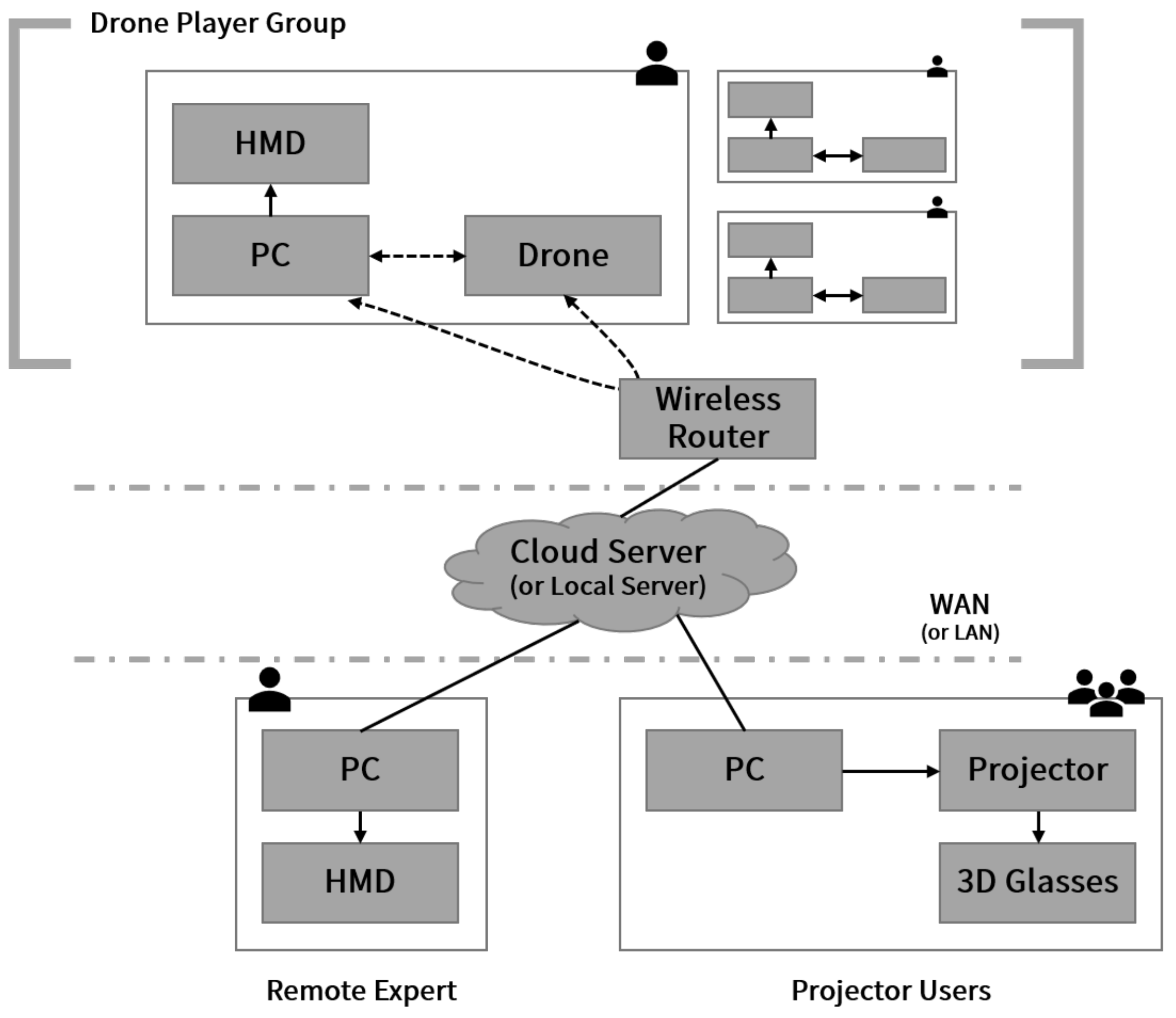
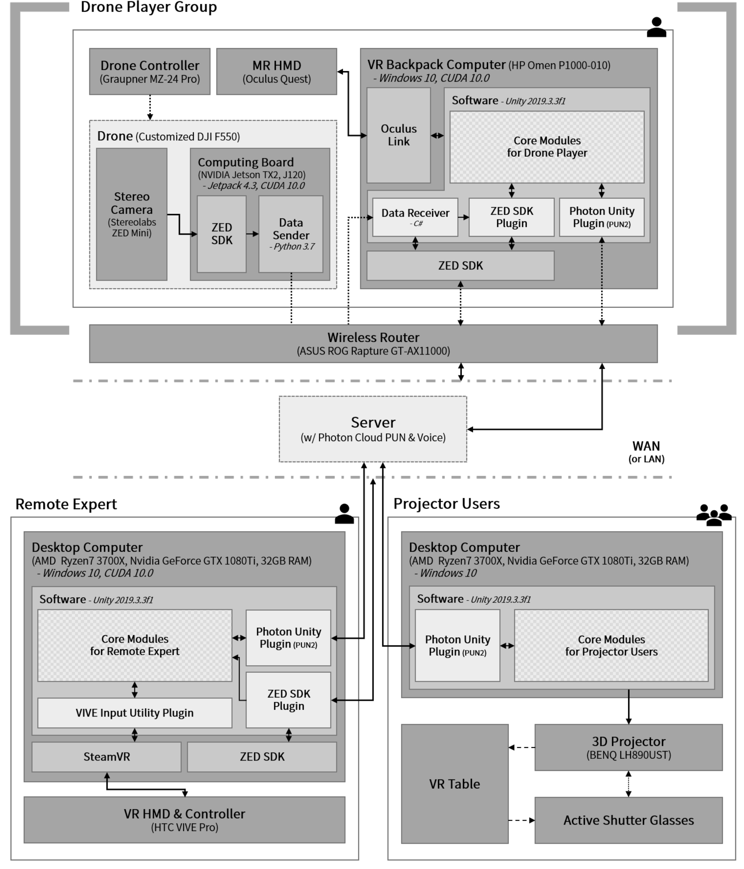
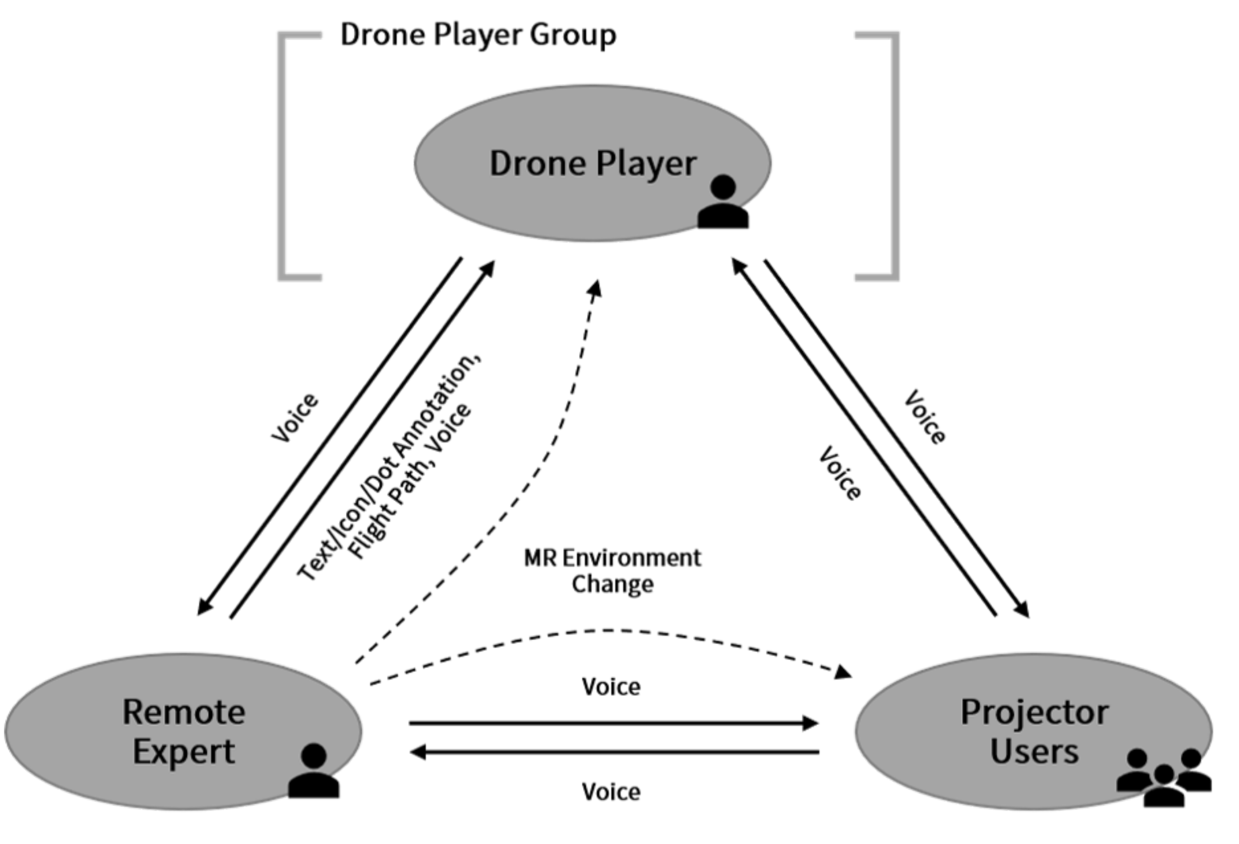
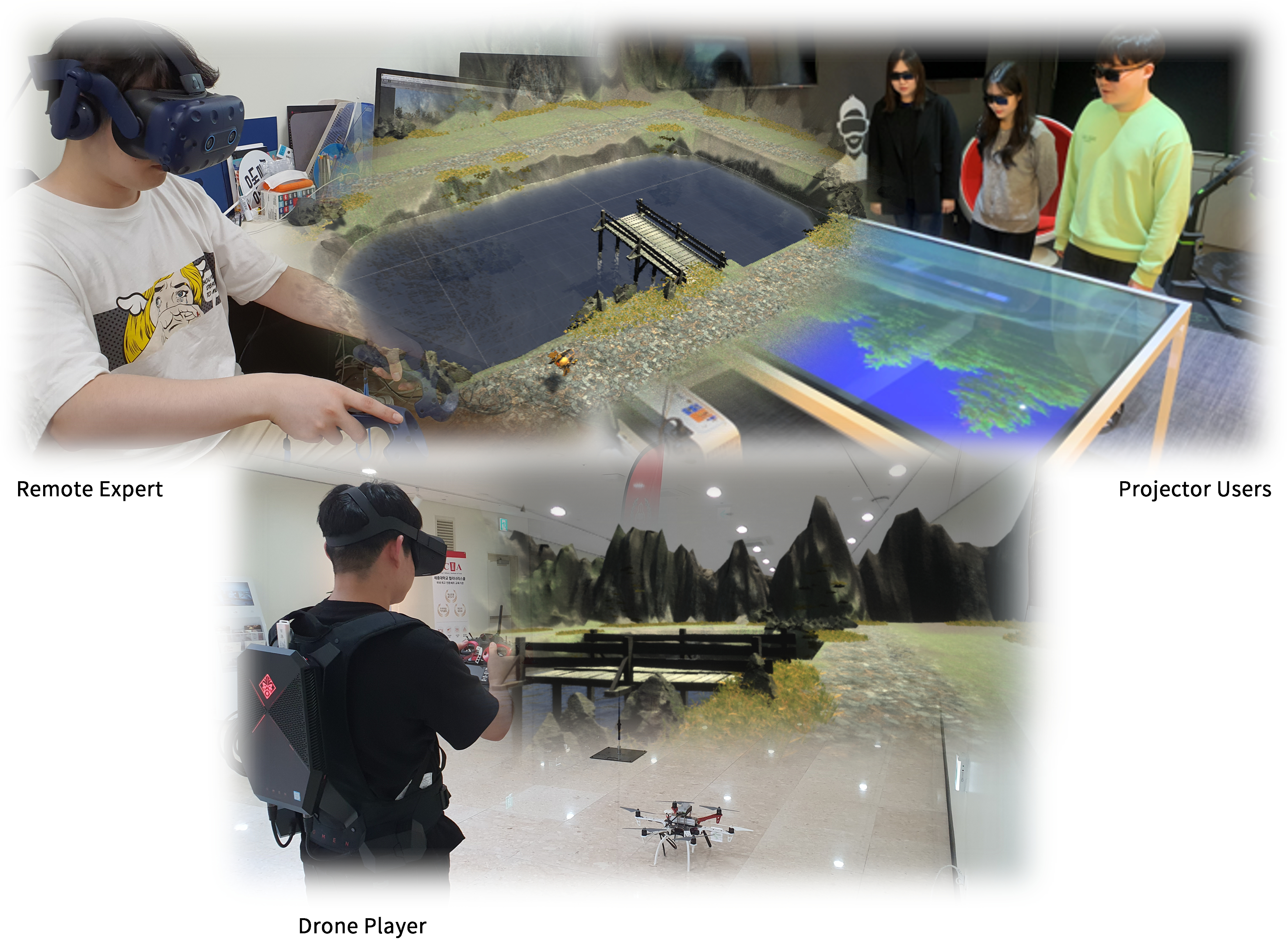
  • We propose a remote training system for FPV drone flying. The drone player, remote expert, and projector user are the components of the system. We define their roles and describe their configuration.
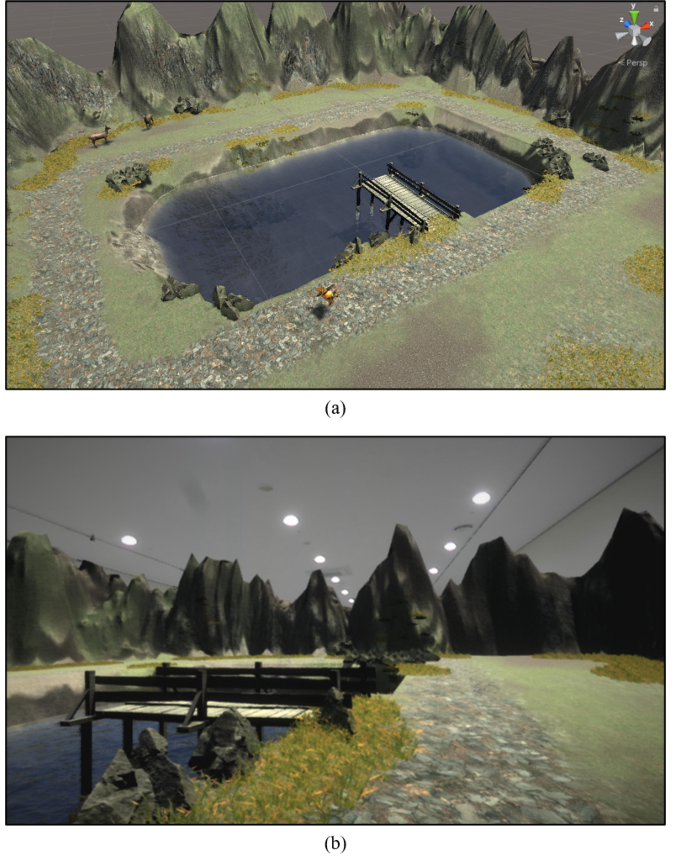
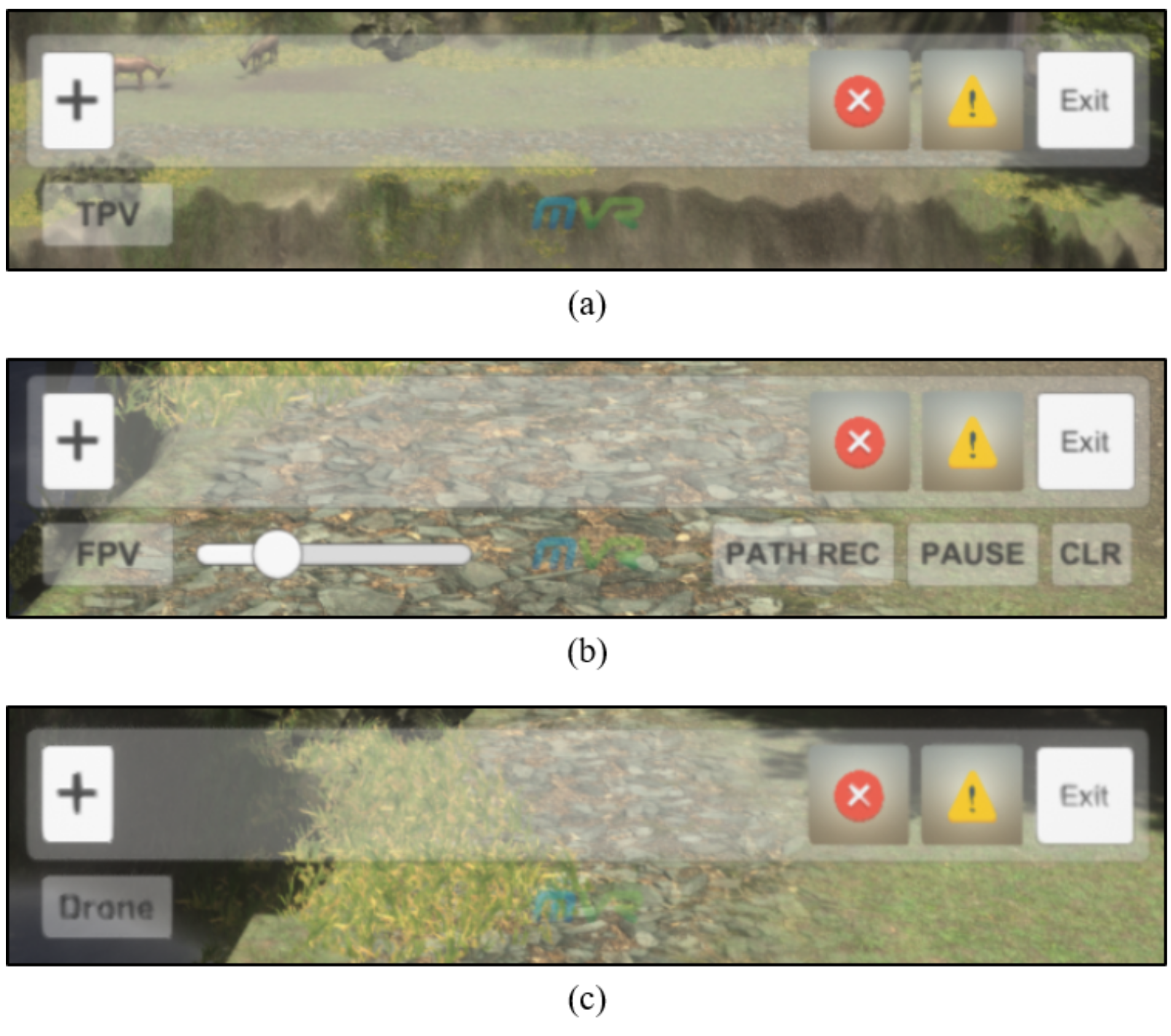
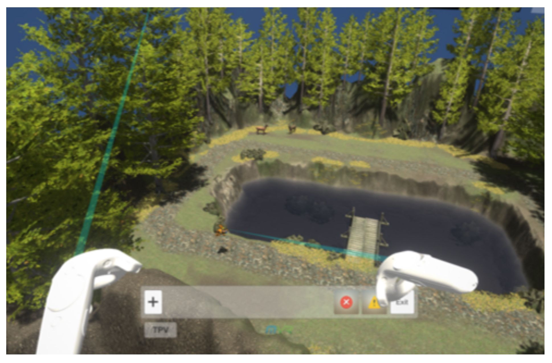
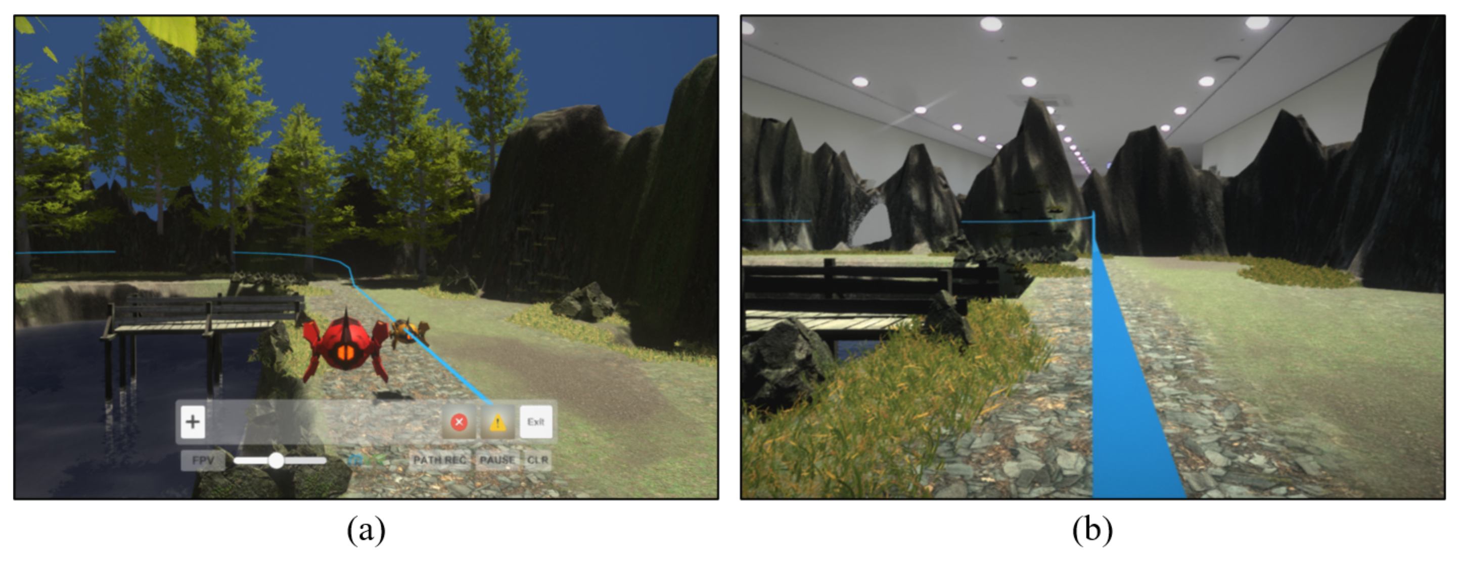
  • We introduce a virtual environment specifically configured for drone flights. We also present a user interface that is specifically designed considering the role of the remote trainer.
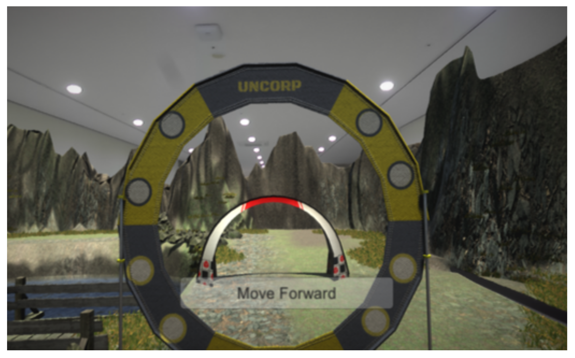
  • We present a user interaction and remote communication method that is suitable for remote training for flying FPV drones. We also describe the implementation method and discuss the results.
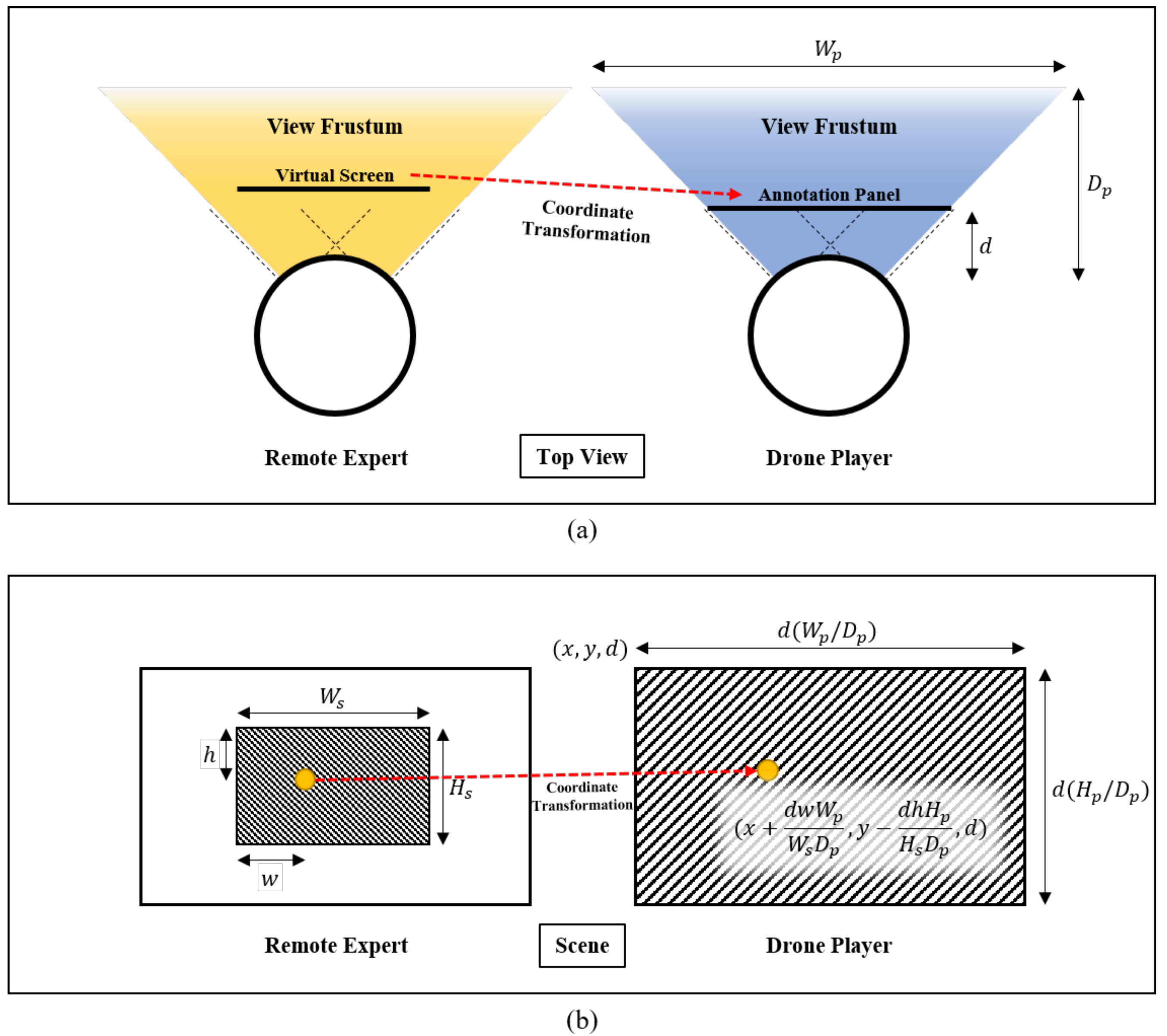
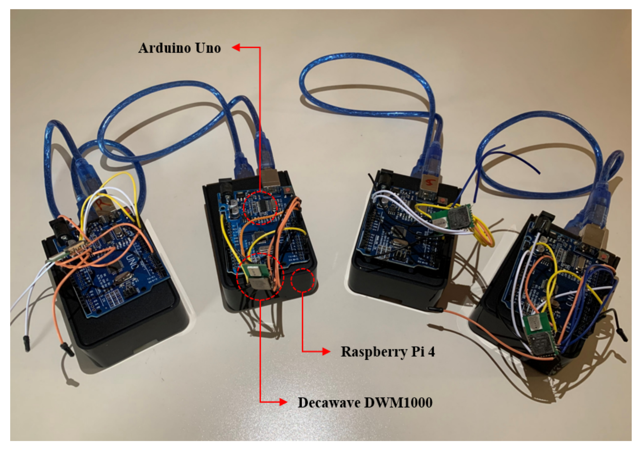
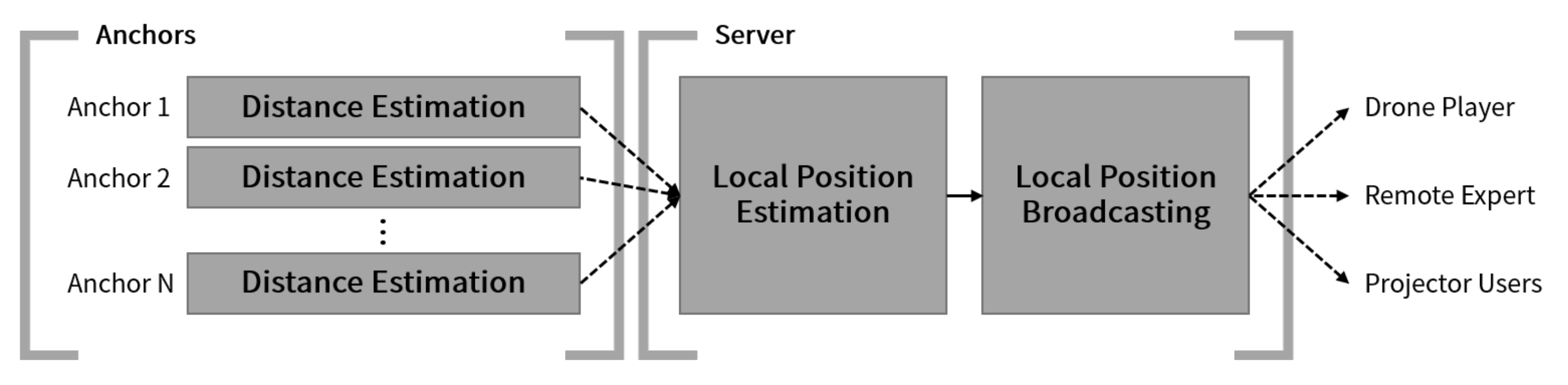
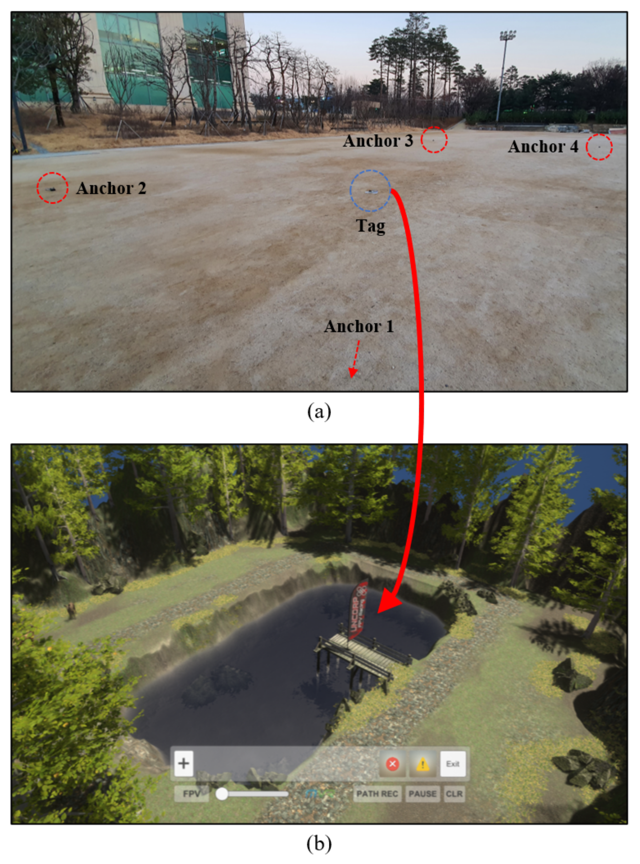
  • We present a configuration method for a virtual flight environment using an ultra-wideband (UWB) wireless communication sensor. This method allows the environment to be configured according to the intentions of the drone pilot, who is present in the actual drone flight environment. Hence, a two-way configuration, instead of a one-way configuration by the remote expert, is possible.

2. Related Work

2.1. Drones and Virtual/Mixed Reality

VR is a “realistic experience” technology whereby a user can realistically interact in an artificial environment composed of computer graphics. It is usually experienced in real time by wearing a head-mounted display (HMD). The MR environment is created in real space and is configured such that various virtual objects exist and appear natural in it. The MR technology includes augmented reality (AR) and augmented virtuality (AV) [1].
With the advancement of technology, an increasing number of studies have been concerned with drone flights based on VR and MR. Rizwan et al. designed and implemented a VR-based real-time monitoring system that enables the efficient and immediate supply of medicines in emergency situations by using drones [2]. Using a drone equipped with a camera in an indoor environment covered by a wall, Erat et al. designed and implemented an MR system that enables a user wearing a Microsoft HoloLens HMD [3] to have X-ray-like vision [4]. In addition, studies that use VR and MR technologies to support drone flights are also in progress. Liu et al. designed and implemented a system in which drone missions can be planned in VR [5]. Vaquero-Melchor et al. proposed a visualization system [6] that can easily define drone missions in MR using Microsoft HoloLens HMD [3]. In a subsequent study, Vaquero-Melchor et al. presented a method for applying a traditional desktop-based user interface to an MR configuration [7].
Various studies that combine drones with VR and MR technologies have been conducted. However, research that considers FPV drone flights has remained at an early stage. In [8,9], it was attempted to fly an FPV drone equipped with a stereo camera using an Oculus HMD [10], and user experiences including motion sickness and stereoscopic perception of stereo-image-based drone flights were analyzed [9]. Moreover, research was conducted on a user interface that allowed the user to fly an FPV drone by moving his/her head and using a joystick in a similar system configuration [11]. Piumsomboon et al. proposed a system that provides a flying telepresence experience to the pilot in an MR environment supporting multiple scales by using a drone equipped with stereo cameras that can adjust the interpupillary distance [12]. Kim et al. presented a method for constructing an MR environment for flying FPV drones by creating virtual obstacles based on objects in real space [13,14]. The immersion experienced by a pilot wearing an HMD during FPV drone flight in MR was analyzed through user evaluation [14].

2.2. Remote Collaboration and Communication between Multiple Users in Virtual/Mixed Reality

Most studies on VR and MR were conducted considering only a single-user environment. However, hardware improvements and the emergence of 5G mobile communications networks, which are characterized by ultra-high speed, ultra-low latency, and ultra-connectivity, have recently been used to enable multiple users to interact and share the same virtual environment in real time.
In general, collaboration refers to multiple people in the same place and situation, working cooperatively and deliberately to achieve shared goals. To support collaboration in a system employing VR and MR, a shared VR environment as well as synchronized information must be provided to all users in real time. Cavallo et al. proposed and implemented a collaborative information analysis system called Dataspace, which utilizes both VR and MR technologies and allows interactions between multiple users [15]. Kunert et al. implemented a VR-based collaborative system whereby users can interact and share the same virtual environment while using several 3D projectors to individually project onto physically separated screens and tables [16].
The method whereby multiple users in physically different spaces collaborate in VR and MR can be configured in various ways depending on the type and structure of the task. Piumsomboon et al. presented the giant-miniature collaboration (GMC) method, which uses a 360° camera that supports six degrees of freedom. This method allows an MR user to collaborate with a remote VR user, who is represented by a miniature virtual avatar at the position of the camera [17]. Norman et al. used MR HMDs and desktop PCs to develop a prototype system for remote collaboration. Thereby, the effect on the MR user who performs the actual tasks at the worksite can be analyzed according to the roles assigned to the remote users [18]. Teo et al. proposed a remote collaboration system that uses both 360° video and 3D virtual models. The system was configured to maximize the advantages and negate the drawbacks of each method [19]. Lee et al. considered one-to-many collaboration in MR and proposed three field-of-view sharing technologies based on the 2D video, 360° video, and 3D virtual models. The three technologies were compared in terms of usability through user evaluation [20]. Rhee et al. designed and implemented an augmented virtual teleportation (AVT) system that enables high-fidelity remote collaboration in an MR space. It was demonstrated that this system allows the remote VR user to share their situation and work with, or convey instructions to the user who controls virtual objects in the MR space, where 360° cameras have been installed [21].
In order for multiple users in virtual space to collaborate seamlessly, each user should be able to express his/her thoughts and intentions verbally or non-verbally. In addition, the other users should be able to recognize and accurately understand his/her intentions. Kim et al. configured visual communication signals complexly for remote collaboration in MR and conducted user evaluations. Moreover, meaningful communication methods were proposed and analyzed from the perspective of conveying user intentions and performing tasks [22].
Irlitti et al. configured a system in which VR and MR are combined to enable multiple users to collaborate using various communication signals based on spatial perception. The effects of these cognitive signal on factors such as user spatial perception and work progress were analyzed through user evaluations [23].

2.3. User Interface in Virtual/Mixed Reality

The user interface enables the system to recognize and process the tasks intended by the user. It comprises a hardware and a software component. In VR and MR, the user should interact with the virtual space and the virtual objects therein. Hence, this should be considered in the design of the user interface.
VR is based on virtual space created using computer graphics. Therefore, an interface through which the user recognizes and uses the objects in real space is not suitable for VR. Accordingly, it is common to employ an interface that uses the controller or hand-tracking method shown in Figure 1. The controller uses sensors to track precise positions, and is equipped with buttons and a trackpad. Hence, the controller is quite sensitive and provides tactile feedback through vibrations and other means. However, the user should hold the controller in both hands. Hence, the user can easily become fatigued, and natural interaction is unlikely. If the hand-tracking method is used, the user can interact using his/her hand without the need for separate hardware. However, it is not easy to perform detailed manipulations because the accuracy of this method is relatively low owing to the limitations of computer vision and object recognition technology. Moreover, as both the controller and the hand-tracking method depend on the position of the user, he/she can only interact with virtual objects that are near him/her. To alleviate these drawbacks, the characteristics of the depth axis of space should be considered. As shown on the left of Figure 1, the system is configured to utilize a laser pointer that uses ray casting to enable interaction with distant virtual objects [24].
Unlike VR, MR uses virtual graphics blended into the real world. Therefore, objects placed in the real space can be used freely, and the user interface can be configured more flexibly. Furthermore, the aforementioned controller and hand-tracking method can be used as is. In addition, a sensor can be attached to an object for tracking. Thus, by mapping this object to a virtual object, extended user interactions can be induced.
Such interfaces can reflect user intentions and actions in the VR and MR space. They aid the user in interacting with the space or virtual objects therein. However, an additional virtual user interface is required to check or manipulate dense, 2-dimensional information consisting of text or icons. The Oculus Quest HMD [10] provides a virtual user interface based on a 2D canvas. The user can manipulate the interface using a laser pointer integrated with the controller or the hand-tracking method.

2.4. Ultra-Wideband Wireless Communication Sensor and Position Estimation Method

UWB wireless communication is a technology suitable for short-range wireless communication such as Bluetooth. It transmits and receives data using impulse signals with a very short pulse width of less than 1 ns, and a wide bandwidth of 500 MHz or greater [25]. Ultra-wideband wireless communication has low power consumption and is robust to signal interference. It has broader coverage than Bluetooth and supports communication speeds of 100 Mbps and higher. Furthermore, the distance between UWB sensors can be measured with an error of tens of centimeters or less because the distance estimation precision is high. Hence, UWB sensors are useful for estimating distance [26]. Apple Inc. included a chip containing a UWB sensor in its iPhone 11 smartphones, which were released in 2019. This sensor is utilized for services and applications that require distance estimation between iPhone 11 and products by other companies [27]. Other smartphone manufacturers, such as Samsung Electronics Co, Ltd., are also beginning to include UWB sensors in their newly released products [28].
The distances between an object and three or more reference points can be measured, and the relative position of the object can be estimated using multilateration [29]. This method is used in a wide area to estimate the location of a wireless communication device within the cell range of several base stations, or to estimate the position of a global positioning system (GPS) receiver using GPS satellites. In a narrow area, this method is widely used for estimating the position of an indoor object using Bluetooth beacons or UWB sensors. Pozyx has developed solutions for estimating the position of an indoor object using UWB sensors [30].
If an error occurs in the distance measurement, the estimated position may be inaccurate, or it may not be possible to estimate the position at all. The Nelder–Mead method [31] uses numerical analysis to solve nonlinear optimization problems for which the derivatives cannot be estimated. Based on the distance data thereby estimated, the relative position of a certain object can be effectively approximated by minimizing the error.
In this study, we designed a virtual flight environment suitable for FPV drone flights in MR and implemented a system such that the elements of the virtual environment can be changed through the interactions of the users, who are the components of the system. All users of the proposed system can share the same virtual flight environment by configuring the system to seamlessly combine with the VR environment for flight training and collaborate to fly the drone by using various audiovisual communication methods. Then, we proposed various interfaces designed by considering users manipulating the virtual environment and conveying flight instructions and considered interactions that can be performed using these interfaces. Furthermore, a proposed method for manipulating elements of the virtual flight space using UWB sensors enables the creation of a virtual environment in MR based on real space.

3. Remote Training System for Drone Flight in Mixed Reality

3.1. System Structure and Components

Figure 2 shows the overall configuration of the proposed system. The system primarily consists of clients and a server. The clients comprise the drone player group, the remote expert, and the projector users. The server processes user requests and controls services. All components are connected to the network by wire or wirelessly, and they transmit and receive data in real time. Figure 3 shows the detailed structure of the system.
The drone player group comprises one or more drone players who know the basic flight control operations. Each drone player needs a computing device, an FPV drone equipped with a stereo camera, a computer for performing system functions, such as MR rendering and remote communication, and an HMD to experience the MR environment from the drone viewpoint. The picture on the left of Figure 4 shows a drone player wearing an Oculus Quest HMD and an HP Omen VR Backpack computer while holding a drone controller. For a group consisting of multiple pilots, all users must wear this equipment. Figure 5 shows the FPV drone used in the system. After voltage distribution using a Matek Systems UBEC Duo regulator, an Nvidia Jetson TX2 board computing device and an Auvidea J120 carrier board with a wireless communication antenna installed on it were mounted on an DJI F550 hexacopter assembled for this study [32]. In addition, a Stereolabs ZED Mini stereo camera was connected to the Auvidea J120 carrier board with a high-quality USB 3.0 cable to obtain the FPV images and configure the MR environment. The software for transmitting the stereo images and IMU sensor data from the Nvidia Jetson TX2 computing device to the network was implemented in Python using the Stereolabs ZED SDK. This software enables wireless streaming of flight images, and allows the estimation of the position and direction of the drone.
The remote expert is proficient in drone flying and configures a virtual flight environment in a physically different space from that of the drone player group. He/she utilizes various remote communication tools to provide the drone player with instructions appropriate for the flight situation. The picture on the right of Figure 4 shows an expert using this system to configure a virtual environment for drone flying while wearing an HTC Vive Pro HMD.
The projector users can see the virtual flight environment and the flight situation by using the images projected by the 3D projector while wearing 3D active shutter glasses. Figure 6 shows projector users viewing 3D images using the 3D projection table that was specifically constructed for this study using special glass processed by Stewart Glass and a BENQ 3D projector capable of projecting images from a short distance. Using this simple method, multiple users can check the 3D virtual environment and the flight situation by viewing the images projected onto the table while wearing the glasses. In addition, the projector users can communicate by voice with the drone players or the remote expert using microphones and speakers.
The server was configured using the Photon Cloud. The server streams data in real time between the drone players, the remote expert, and the projector users. This stream contains essential data for key functions of the system, such as sharing the virtual environment, synchronizing the drone position, and processing remote communication.

3.2. Design of the Virtual Environment Suitable for Remote Drone Flight Training

Typical drone flights are possible within the wireless transmission/reception range of the drone controller. Hence, drones are flown near the remote pilot. Therefore, it is necessary to design and implement a virtual environment accordingly. Figure 7 shows the virtual flight environment of the proposed system. It was implemented in Unity v2019.3.3.f1 and C#. The system was configured such that the remote expert wearing an HMD can check the overall flight environment and the flight situation of the drone by looking down at 30° below the horizontal in the forward direction. Moreover, real-time images transmitted from the stereo camera mounted on the drone are displayed in front of the expert. In addition, several curved screens were placed farther away, so that all images can be viewed simultaneously even when they are transmitted from multiple drones.
The environment of the projector users has the same implementation as that of the remote expert. Hence, the projector users can check the flight situation by looking at the table onto which the images are projected. Figure 8 shows the image projected by the 3D projector onto a table and the 3D flight environment seen by a user wearing 3D glasses. When a superimposed image is projected on the table by the 3D projector, as shown on the left of Figure 8, the user can see a 3D image as shown on the right in Figure 8, thereby enabling immersive viewing.
However, as the graphics that match the actual flight space increase, the pilot’s perception of real space is reduced. Hence, it becomes more difficult for a drone player who experiences the virtual environment in MR to wholly focus on piloting the drone. Therefore, as shown in Figure 9, the virtual environments of the drone player and the remote expert share the same overall configuration; however, the supplementary virtual objects are not rendered on the HMD of the pilot.

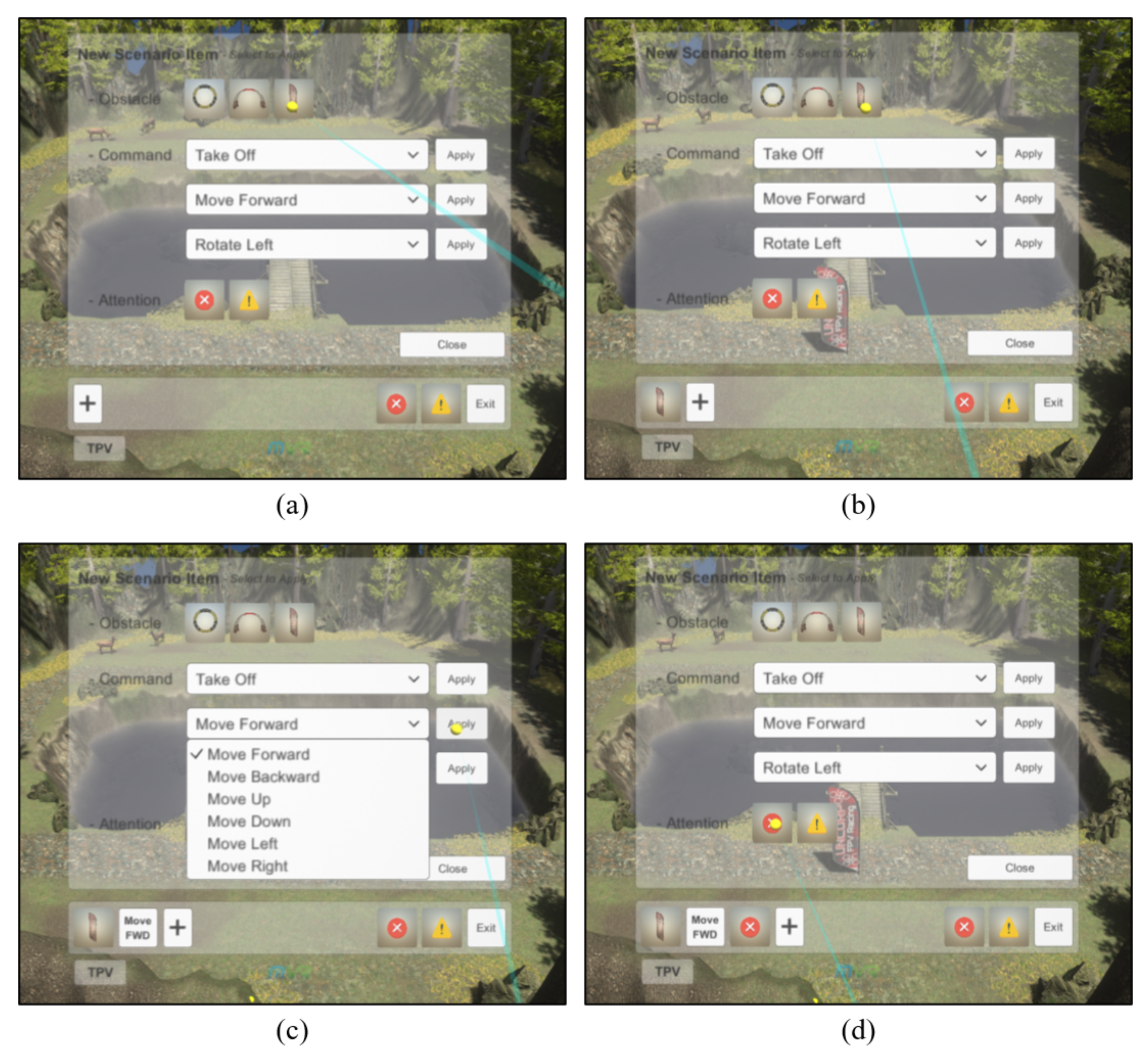
3.3. User Interface Configuration

The scenario timeline and attention dock (STnAD) is a virtual user interface for drone flight training designed for the remote expert [33]. It delivers sequential flight instructions to the pilot flying the drone in MR. It also provides visual guidance that requires instant attention and concentration. However, it only includes an interface for an omniscient third-person view (TPV) of the overall flight environment. Therefore, it fails to facilitate effective user interactions and is not suitable for the intended tasks.
Figure 10 shows the extended STnAD (ex-STnAD) user interface, which was designed by extending the STnAD for use by the remote expert in the proposed system. It not only includes all the components of the STnAD but also accurately carries out user intentions by flexibly switching between three different viewpoints listed in Table 1. In particular, the interface allows the expert to carry out interactions in proximity to the virtual environment.
Figure 11 shows a remote expert using the ex-STnAD interface tools to configure a new flight training scenario from an omniscient TPV. The expert can add new virtual obstacles to the flight environment or specify flight instructions in chronological order using these tools. The expert can also configure the environment in advance to require the attention and concentration of a drone player at certain points in time.
If a problem occurs when the system processes various tasks, or if the user requests tasks that are not allowed by the system, the system should report the problem immediately and receive a request for subsequent processing. The proposed system provides a text-based modal window interface whereby information useful or important to the user is displayed, and user requests are inputted. This is implemented by calling a coroutine in Unity, and thus the other user interfaces are not blocked. Hence, this coroutine suspends execution until the user input in the modal window is received. However, this non-blocking mechanism does not preempt or stop user requests or the processing of other tasks. Figure 12 shows the modal window that is displayed when the expert requests a nonallowed operation. The system waits until the user enters input, and subsequently the task is processed accordingly.
The remote expert is provided with the previously described virtual user interface. However, such a virtual user interface is not provided to the drone player. The player sees the flight space as MR; thus, unnecessary graphic information could unintentionally induce the pilot to look away from the real space, thereby interfering with his/her focus on flying the drone. Moreover, the pilot is holding the drone controller with both his/her hands. Hence, it is not easy to use a virtual user interface. However, when flight instructions are given by the remote expert, or instant attention and concentration is required, text or graphic information is intuitively displayed on the HMD, as shown in Figure 13. Thus, the drone player can check the instructions immediately.
The virtual user interface of the expert is synchronized with the table viewed by the projector users and is projected onto the table along with the virtual flight space. Hence, the projector users can check the instructions of the expert. However, separate devices for manipulating the interface are not provided, and thus the projector users cannot perform other interactions.
Unlike the drone players or project users, the remote expert should actively utilize the provided virtual user interfaces in various ways. Consequently, mechanisms for manipulating the virtual interfaces should also be considered. The proposed system allows the expert to manipulate functions using the HTC Vive Pro controller, as shown in Figure 14. The expert performs the intended function by checking the virtual controller and laser pointer displayed on the HMD and pressing the physical buttons on the controller. In addition, the system provides the expert with familiar controller operations through the trackpad to pilot the virtual drone in Mode 2. Using the Mode 2 control method, the user can control the throttle and yaw of the drone with the left stick, and the pitch and roll with the right stick. This method is commonly used for piloting drones.

3.4. User Interactions and Remote Communication

In order for the expert to provide a drone player with remote flight instructions, or for all users to exchange their opinions seamlessly, user interactions with the system should be carefully considered, and an appropriate communication method should be developed. Figure 15 shows the structure of the user interactions and remote communication that occur between the components of the proposed system, which was designed considering remote training situations and methods for flying FPV drones; accordingly, the interactions and communication by the expert are more important than those of the drone players and projector users.
The remote expert can select the viewpoint button of the ex-STnAD interface using the seamlessly switch between viewpoints: omniscient TPV, FPV (or close TPV), and drone view. This can change the virtual flight environment effectively and convey useful flight instructions to the drone player immediately or in a specified order. An expert who has changed the viewpoint several times using the interface is shown in Figure 16. When the viewpoint is changed, the movement is adjusted using Equation (1). The function in Equation (1) returns the position vector at time t [ 0 , p ] when the viewpoint transition speed a, the elapsed time p, the position vector at the departure time s o , and the position vector at the arrival time s d are given as parameters. Therefore, the 3D user-viewpoint coordinates can be determined for each frame.
S ( t ; a , p , s o , s d ) = t a p a ( s d s o ) + s o
The expert can design flight training scenarios using the extension tools of the ex-STnAD interface from any viewpoint. The flight instructions can be configured in chronological order by selecting various scenarios provided by the tools using the controller. Figure 17 shows the process of sequentially inserting icons into the interface as the expert configures flight training scenarios from an omniscient TPV using these tools. If the icon inserted in the interface is selected using the controller, the corresponding scenario is removed. When a virtual obstacle is added, it is placed in the virtual environment and mapped to an icon as a pair. As the obstacle–icon pair is managed internally, the obstacle is deleted if the corresponding icon is removed from the interface. Algorithm 1 shows the implementation of this operation in pseudocode.
Algorithm 1 Training scenario configuration using extension tools
1:  l i s t { }                ▹ scenario list14:     if input r m v then
2: for each frame do15:         if r m v obstacles then
3:      i n s , r m v getUserInput()16:             o getMapping( r m v )
4:     if input i n s then17:            destroyObstacle(o)
5:          e insert( l i s t , i n s )18:         end if
6:         if  e obstacles then19:         remove( l i s t , r m v )
7:               o initializeObstacle(e)20:         if getLength( l i s t ) > 0 then
8:              setMapping(e, o)21:             e getFirstElem( l i s t )
9:              syncObstacle(o)22:            if e obstacles then
10:         else if getLength( l i s t ) = 1 then23:                sendAnnotation(e)
11:            sendAnnotation(e)24:            end if
12:         end if25:         else
13:     end if26:            clear()
27:         end if
28:     end if
29: end for
The expert can change the position of the obstacles placed in the virtual flight space by performing a drag-and-drop operation using the controller. If a particular obstacle is selected using the controller and then lifted up in the air by dragging it while the physical button is held down, an auxiliary line, which indicates the position on the ground above which the obstacle is currently placed, is displayed, as shown in Figure 18. This auxiliary line is introduced to improve the limit of user perception of 3D space. It is rendered as a line segment using a line perpendicular to the ground beneath the virtual obstacle. If the physical button on the controller is released to perform a drop operation in this state, the obstacle is placed at the position corresponding to the foot of the perpendicular line. The coordinates of the updated position of the virtual obstacle are transferred to all other users through the server in real time and are synchronized.
The components of the proposed communicate using text annotation, icon annotation, dot annotation, flight path guidelines, and voice. All users can use voice-based communication. However, all other communication methods are used only for the interactions of the remote experts to convey information to the drone player.
Text annotation is used to convey flight instruction scenarios by the expert in text format. The configuration method for such scenarios was described above in one of the earlier processes. Scenarios thereby generated should be sequentially conveyed to the drone player. For this purpose, the system conveys the instructions corresponding to the leftmost icon in the ex-STnAD interface of the expert to the pilot through the server. The instructions are rendered as text, as shown in Figure 13. If the drone player carries out the instructions correctly, the expert removes the corresponding icon. Subsequently, the remaining icons are rearranged, and the next instructions are delivered. Icon annotation is performed in the same manner. However, it is used when visual communication in the form of an image is effective; for example, when attention and concentration are required. Figure 19 shows icon annotations conveyed to the drone player.
Dot annotation is used to request the drone player to pay attention to a specific position in the field of view during flight. As shown in Figure 20, the expert can select a screen placed in the distant view of the virtual flight space using the controller and use the screen as an interface for dot annotation. As real-time video from the stereo camera mounted on the drone of the pilot is streamed to the screen, the expert can check the flight environment and provide appropriate instructions. If the expert points to a specific position on the enlarged virtual screen with the laser pointer of the controller, a dot-shaped pointer is synchronized and displayed in the field of view of the pilot at the same position. Here, the virtual screen of the expert is curved, that is, a 2D plane is transformed into a curved plane. However, the field of view of the pilot is a 3D space. Therefore, the coordinates of the pointer position should be appropriately converted. Figure 21 shows that the plane coordinates on the screen are converted into appropriate spatial coordinates, considering the view frustum seen on the HMD of the pilot. If the expert selects the enlarged screen again with the controller, the system returns to the previous state, and the transfer of dot annotations is halted.
The flight path guidelines are a communication method that visually conveys the intention of the expert by showing the recommended flight path to the pilot as a smooth 3D curve in the virtual space. The remote expert can draw a 3D curve in the virtual space by activating the flight path recording function provided by the ex-STnAD interface from the FPV, and moving the virtual drone using the controller. The coordinates of the virtual drone are recorded at short intervals, and adjacent points are connected with a line segment to form the curve. This procedure is performed repeatedly until the flight path recording is paused. The continuous coordinate data constituting the flight path are transmitted to the drone pilot through the server in the form of a stream. The smooth curve is rendered in the MR flight environment of the pilot as explained previously. Figure 22 shows the flight path recorded by the expert rendered on the HMD of the drone player. The expert can record several discontinuous flight paths or delete a previously recorded flight path using the ex-STnAD interface.
Voice is the most common yet effective communication method. Unlike the previously presented methods, the voice method depends on hearing rather than seeing. The proposed system supports remote voice conversations using the Photon Voice library. Thus, all users can share their opinions immediately. In particular, as the drone player and the projector users have limitations with regard to visual communication, by supporting voice communication, they can actively communicate with the remote expert, and flight training can proceed smoothly.

3.5. Configuration of Bidirectional Virtual Environments using Ultra-Wideband Wireless Communication Sensors

In previous sections, methods for configuring a remote training system for drone flight in MR were explained in detail, and the results of the implementation were presented. Using this system, the remote expert can configure a virtual environment and convey flight instructions. In addition, the drone player can maneuver the drone according to the instructions received in a given MR environment. However, it is difficult for this type of unidirectional virtual environment configuration to consider the flight space of the pilot in the MR environment. Hence, the possibility that the environment configuration or flight instructions are intermittently inappropriate cannot be ruled out. To compensate for this drawback, the drone player can use UWB sensors to manipulate certain elements of the virtual flight environment to configure a bidirectional environment. Furthermore, this method can be additionally applied to the system.
In this study, a UWB sensor was constructed by soldering a Decawave DWM1000 module to an Arduino Uno board. Figure 23 shows a Raspberry Pi 4 board combined with the UWB sensor, adhering to the USB standard. Figure 24 shows the overall schematic diagram of the virtual environment using multiple UWB sensors, which are primarily classified as anchors or tags according to their roles. The former estimate the distance to the latter by calculating the round-trip time for sending and receiving data using the 4-way handshake method [34]. The distance data are processed by the Raspberry Pi board, to which the sensors are connected, and the processed data are sent to the system server. The server uses the coordinates of the anchors mapped to the appropriate position in the virtual flight space and the estimated distance between each anchor and a tag to reasonably estimate the spatial coordinates of the tag by using multilateration and the Nelder–Mead method [31]. The estimated position of the tag is then sent to all system users in real time. Changes based on the pre-designated tags are reflected immediately in the virtual space. Thus, all users can experience an identical flight environment.
Figure 25 shows an obstacle created at the tag position in the virtual flight space when four sensors functioning as anchors and one sensor designated as a tag are placed in real space. The obstacle is shared with the drone player as well as the virtual flight environment of the remote expert and projector users. There could multiple tags. As the number of anchors increases, the coverage is widened, and the accuracy of tag position estimation is improved. That is, a more diverse bidirectional virtual environment can be configured by scaling out the sensors.

4. Conclusions and Future Work

We proposed a remote training system for flying FPV drones in MR and described the process of designing and implementing this system in terms of the user interface, user interactions, and remote communication. Drone players, the remote expert, and projector users can carry out the tasks assigned to their roles in the shared virtual flight space using the proposed system. Furthermore, drone players can manipulate the elements of the virtual flight environment using UWB sensors, which allows them to configure a bidirectional environment.
The drone player views the MR flight space through an HMD based on the real space captured by a stereo camera mounted on the FPV drone. The player flies the drone by operating the drone controller according to the flight instructions of the remote expert, who uses the ex-STnAD virtual user interface provided by the system while wearing an HMD to configure the virtual flight environment and plan flight scenarios. The instructions are conveyed using various communication methods, such as text annotation, dot annotation, and flight path guidelines. The projector users wear 3D active shutter glasses and check the 3D virtual flight environment and situation projected onto the table by a short-throw 3D projector.
It is expected that the proposed system will be used for remote drone flying training. It is also expected that it will be used for flight training related to tasks involving drones in various fields, such as entertainment, defense, and firefighting.
For future research, user evaluation of the proposed system should be conducted to verify its usability and analyze issues so that the system can be improved, and better user experience can be provided. In addition, a study should be conducted to enhance the system and make it more realistic by reflecting in-depth opinions of drone experts.

Author Contributions

Conceptualization, Y.-G.G. and S.-M.C.; Methodology, Y.-G.G.; Software, Y.-G.G., H.-S.K., J.-W.L. and M.-S.Y.; validation, Y.-G.G.; formal analysis, Y.-G.G.; investigation, Y.-G.G.; resources, Y.-G.G. and S.-M.C.; data curation, Y.-G.G.; Writing–original draft preparation, Y.-G.G.; Writing–review and editing, Y.-G.G., M.-S.Y. and S.-M.C.; visualization, Y.-G.G.; supervision, S.-M.C.; project administration, S.-M.C.; funding acquisition, S.-M.C. All authors have read and agreed to the published version of the manuscript.

Funding

This research was financially supported by the MSIT(Ministry of Science and ICT), Korea, under the ITRC(Information Technology Research Center) support program(IITP-2021-2016-0-00312) supervised by the IITP(Institute for Information & communications Technology Planning & Evaluation) and the Ministry of Trade, Industry and Energy(MOTIE) and Korea Institute for Advancement of Technology(KIAT) through the International Cooperative R&D program. (Project No. P0016038).

Conflicts of Interest

The authors declare no conflict of interest.

References

  1. Milgram, P.; Takemura, H.; Utsumi, A.; Kishino, F. Augmented reality: A class of displays on the reality-virtuality continuum. Telemanipulator Telepresence Technol. 1995, 2351, 282–292. [Google Scholar]
  2. Rizwan, R.; Shehzad, M.N.; Awais, M.N. Quadcopter-Based Rapid Response First-Aid Unit with Live Video Monitoring. Drones 2019, 3, 37. [Google Scholar] [CrossRef] [Green Version]
  3. Microsoft HoloLens. Available online: https://www.microsoft.com/en-us/hololens/ (accessed on 20 May 2021).
  4. Erat, O.; Isop, W.A.; Kalkofen, D.; Schmalstieg, D. Drone-Augmented Human Vision: Exocentric Control for Drones Exploring Hidden Areas. IEEE Trans. Visual Comput. Graphics 2018, 24, 1437–1446. [Google Scholar] [CrossRef] [PubMed]
  5. Liu, Y.; Yang, N.; Li, A.; Paterson, J.; McPherson, D.; Cheng, T.; Yang, A.Y. Usability Evaluation for Drone Mission Planning in Virtual Reality. In Virtual, Augmented and Mixed Reality: Applications in Health, Cultural Heritage, and Industry; Chen, J., Fragomeni, G., Eds.; Springer: Cham, Switzerland, 2018; pp. 313–330. [Google Scholar]
  6. Vaquero-Melchor, D.; García-Hospital, J.; Bernardos, A.M.; Besada, J.A.; Casar, J.R. Holo-mis: A mixed reality based drone mission definition system. In Proceedings of the 20th International Conference on Human-Computer Interaction with Mobile Devices and Services Adjunct, Barcelona, Spain, 3–6 September 2018; pp. 365–370. [Google Scholar]
  7. Vaquero-Melchor, D.; Bernardos, A.M. Alternative interaction techniques for drone-based mission definition: From desktop UI to wearable AR. In Proceedings of the 18th International Conference on Mobile and Ubiquitous Multimedia, Pisa, Italy, 26–29 November 2019; pp. 1–5. [Google Scholar]
  8. Hayakawa, H.; Fernando, C.L.; Saraiji, M.Y.; Minamizawa, K.; Tachi, S. Telexistence Drone: Design of a Flight Telexistence System for Immersive Aerial Sports Experience. In Proceedings of the 6th Augmented Human International Conference, Singapore, Singapore, 9–11 March 2015; pp. 171–172. [Google Scholar]
  9. Smolyanskiy, N.; Gonzalez-Franco, M. Stereoscopic first person view system for drone navigation. Front. Rob. AI 2017, 4, 11. [Google Scholar] [CrossRef] [Green Version]
  10. Oculus. Available online: https://www.oculus.com/ (accessed on 20 May 2021).
  11. O’Keeffe, E.; Campbell, A.; Swords, D.; Laefer, D.F.; Mangina, E. Oculus Rift Application for Training Drone Pilots. In Proceedings of the 10th EAI International Conference on Simulation Tools and Techniques, Hong Kong, China, 11–13 September 2017; pp. 77–80. [Google Scholar]
  12. Piumsomboon, T.; Lee, G.A.; Ens, B.; Thomas, B.H.; Billinghurst, M. Superman vs Giant: A Study on Spatial Perception for a Multi-Scale Mixed Reality Flying Telepresence Interface. IEEE Trans. Visual Comput. Graph. 2018, 24, 2974–2982. [Google Scholar] [CrossRef] [PubMed]
  13. Kim, D.; Go, Y.; Choi, S. First-person-view drone flying in mixed reality. In Proceedings of the SIGGRAPH Asia 2018 Posters, Tokyo, Japan, 4–7 December 2018; pp. 1–2. [Google Scholar]
  14. Kim, D.; Go, Y.; Choi, S. An Aerial Mixed-Reality Environment for First-Person-View Drone Flying. Appl. Sci. 2020, 10, 5436. [Google Scholar] [CrossRef]
  15. Cavallo, M.; Dholakia, M.; Havlena, M.; Ocheltree, K.; Podlaseck, M. Dataspace: A Reconfigurable Hybrid Reality Environment for Collaborative Information Analysis. In Proceedings of the 2019 IEEE Conference on Virtual Reality and 3D User Interfaces (VR), Osaka, Japan, 23–27 March 2019; pp. 145–153. [Google Scholar]
  16. Kunert, A.; Weissker, T.; Froehlich, B.; Kulik, A. Multi-Window 3D Interaction for Collaborative Virtual Reality. IEEE Trans. Visual Comput. Graphics 2020, 26, 3271–3284. [Google Scholar] [CrossRef] [PubMed]
  17. Plumsomboon, T.; Lee, G.A.; Irlitti, A.; Ens, B.; Thomas, B.H.; Billinghurst, M. On the Shoulder of the Giant: A Multi-Scale Mixed Reality Collaboration with 360 Video Sharing and Tangible Interaction. In Proceedings of the 2019 CHI Conference on Human Factors in Computing Systems, Glasgow Scotland, UK, 4–9 May 2019; pp. 1–17. [Google Scholar]
  18. Norman, M.; Lee, G.A.; Smith, R.T.; Billinghurst, M. The impact of remote user’s role in a mixed reality mixed presence system. In Proceedings of the 17th International Conference on Virtual-Reality Continuum and its Applications in Industry, Brisbane, Australia, 14–16 November 2019; pp. 1–9. [Google Scholar]
  19. Teo, T.; Lawrence, L.; Lee, G.A.; Billinghurst, M.; Adcock, M. Mixed Reality Remote Collaboration Combining 360 Video and 3D Reconstruction. In Proceedings of the 2019 CHI Conference on Human Factors in Computing Systems, Glasgow Scotland, UK, 4–9 May 2019; pp. 1–14. [Google Scholar]
  20. Lee, G.; Kang, H.; Lee, J.; Han, J. A User Study on View-sharing Techniques for One-to-Many Mixed Reality Collaborations. In Proceedings of the 2020 IEEE Conference on Virtual Reality and 3D User Interfaces (VR), Atlanta, GA, USA, 22–26 March 2020; pp. 343–352. [Google Scholar]
  21. Rhee, T.; Thompson, S.; Medeiros, D.; Anjos, R.d.; Chalmers, A. Augmented Virtual Teleportation for High-Fidelity Telecollaboration. IEEE Trans. Visual Comput. Graph. 2020, 26, 1923–1933. [Google Scholar] [CrossRef] [PubMed]
  22. Kim, S.; Lee, G.; Billinghurst, M.; Huang, W. The combination of visual communication cues in mixed reality remote collaboration. J. Multimodal User Interfaces 2020, 14, 321–335. [Google Scholar] [CrossRef]
  23. Irlitti, A.; Piumsomboon, T.; Jackson, D.; Thomas, B.H. Conveying spatial awareness cues in xR collaborations. IEEE Trans. Visual Comput. Graph. 2019, 25, 3178–3189. [Google Scholar] [CrossRef] [PubMed]
  24. LaViola, J.J.; Kruijff, E.; McMahan, R.P.; Bowman, D.A.; Poupyrev, I. 3D User Interfaces: Theory and Practice, 2nd ed.; Addison-Wesley: Boston, MA, USA, 2017. [Google Scholar]
  25. Lee, J.; Su, Y.; Shen, C. A Comparative Study of Wireless Protocols: Bluetooth, UWB, ZigBee, and Wi-Fi. In Proceedings of the IECON 2007—33rd Annual Conference of the IEEE Industrial Electronics Society, Taipei, Taiwan, 5–8 November 2007; pp. 46–51. [Google Scholar]
  26. Zhang, J.; Orlik, P.V.; Sahinoglu, Z.; Molisch, A.F.; Kinney, P. UWB Systems for Wireless Sensor Networks. Proc. IEEE 2009, 97, 313–331. [Google Scholar] [CrossRef]
  27. Six Colors—The U1 Chip in the iPhone 11 is the Beginning of an Ultra Wideband Revolution. Available online: https://sixcolors.com/post/2019/09/the-u1-chip-in-the-iphone-11-is-the-beginning-of-an-ultra-wideband-revolution/ (accessed on 20 May 2021).
  28. Mobile ID World—NXP and Samsung Unveil First Android Device with UWB Technology. Available online: https://mobileidworld.com/nxp-and-samsung-unveil-first-android-device-with-uwb-technology-108132/ (accessed on 20 May 2021).
  29. Fresno, J.M.; Robles, G.; Martínez-Tarifa, J.M.; Stewart, B.G. Survey on the Performance of Source Localization Algorithms. Sensors 2017, 17, 2666. [Google Scholar] [CrossRef] [PubMed] [Green Version]
  30. Pozyx. Available online: https://www.pozyx.io/ (accessed on 20 May 2021).
  31. Nelder, J.A.; Mead, R. A Simplex Method for Function Minimization. Comput. J. 1965, 7, 308–313. [Google Scholar] [CrossRef]
  32. Liu, K.; Chauhan, S.; Devaraj, R.; Shahi, S.; Sreekumar, U. Enabling Autonomous Unmanned Aerial Systems via Edge Computing. In Proceedings of the IEEE International Conference on Service-Oriented System Engineering (SOSE), San Francisco, CA, USA, 4–9 April 2019; pp. 374–379. [Google Scholar]
  33. Go, Y.; Lee, J.; Kang, H.; Choi, S. Interactive Training of Drone Flight Control in Mixed Reality. In Proceedings of the SIGGRAPH Asia 2020 XR, Daegu, Korea, 10–13 December 2020; pp. 1–2. [Google Scholar]
  34. GitHub Repository—Thotro/Arduino-dw1000. Available online: https://github.com/thotro/arduino-dw1000 (accessed on 20 May 2021).
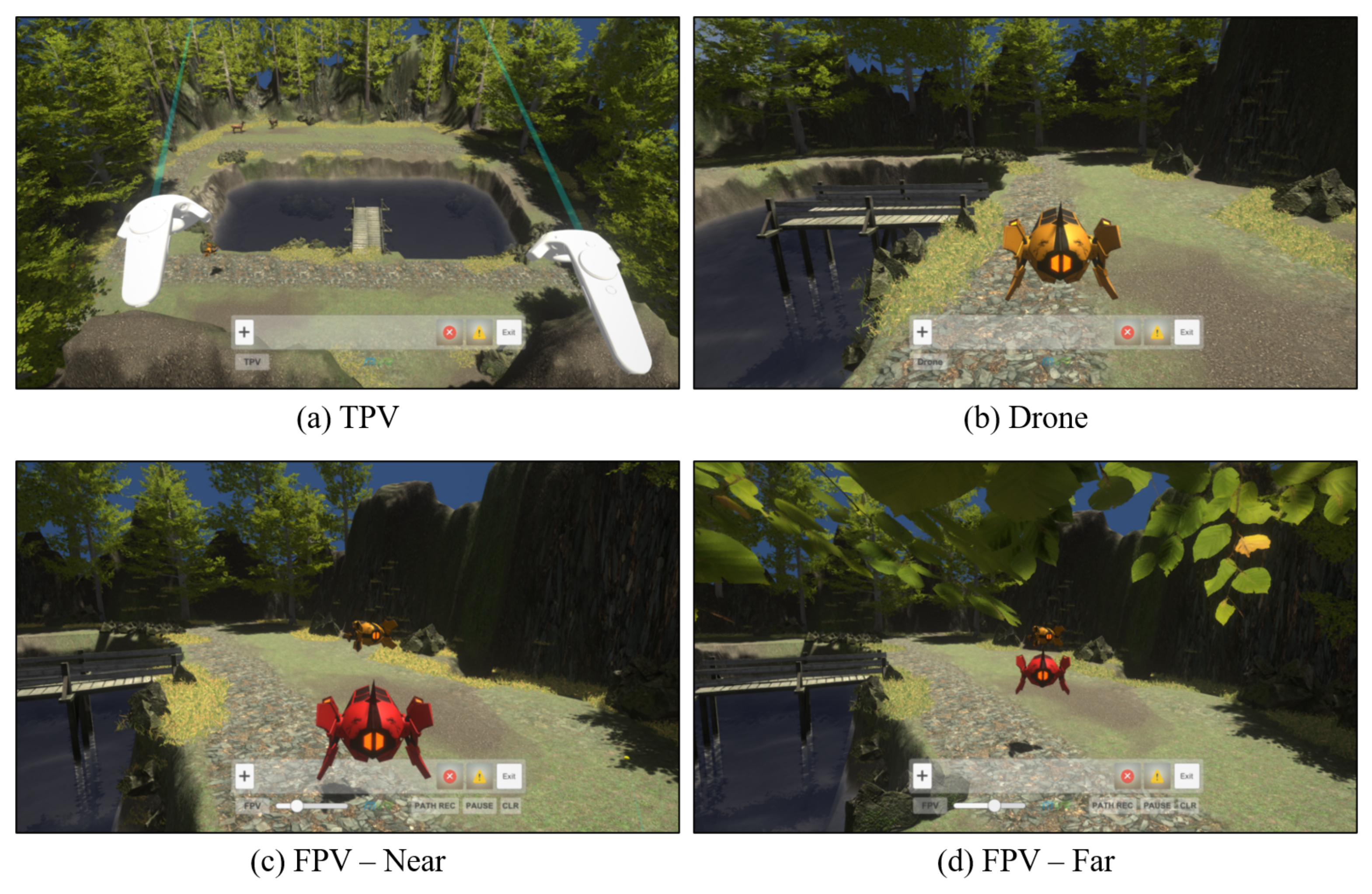
Figure 1. User interface in VR: (a) controller; (b) hand-tracking method.
Electronics 10 02521 g001
Figure 2. System configuration diagram.
Electronics 10 02521 g002
Figure 3. System structure.
Electronics 10 02521 g003
Figure 4. Drone player (left) and remote expert (right).
Electronics 10 02521 g004
Figure 5. Customized DJI F550 hexacopter.
Electronics 10 02521 g005
Figure 6. Projector users.
Electronics 10 02521 g006
Figure 7. System configuration environment of the remote expert: (a) horizontal; (b) 30° below.
Electronics 10 02521 g007
Figure 8. The 3D flight environment on VR table: (a) projected by the 3D projector; (b) as seen by the user.
Electronics 10 02521 g008
Figure 9. MR flight environment of the drone player: (a) bird’s-eye view; (b) as seen by the user.
Electronics 10 02521 g009
Figure 10. ex-STnAD interface for each viewpoint of the remote expert: (a) TPV; (b) FPV; (c) drone.
Electronics 10 02521 g010
Figure 11. Extension tool of ex-STnAD interface: (a) before extension; (b) after extension.
Electronics 10 02521 g011
Figure 12. Modal window.
Electronics 10 02521 g012
Figure 13. Instructional text displayed on the HMD of a drone player.
Electronics 10 02521 g013
Figure 14. Virtual controller and laser pointer rendered on the HMD of the remote expert.
Electronics 10 02521 g014
Figure 15. User interactions and remote communication between components.
Electronics 10 02521 g015
Figure 16. Switching the remote expert’s perspective using ex-STnAD interface: (a) TPV; (b) drone view; (c) FPV close to the virtual drone; (d) FPV far from the virtual drone.
Electronics 10 02521 g016
Figure 17. Configuration of sequential flight training scenarios using a controller. (a) Selection of an obstacle scenario (b) An inserted obstacle-icon in the interface (c) An inserted MOVE-FORWARD-icon in the interface (d) An inserted attention-icon in the interface.
Electronics 10 02521 g017
Figure 18. Auxiliary line of a virtual obstacle.
Electronics 10 02521 g018
Figure 19. Icon annotation displayed on the HMD of a drone player.
Electronics 10 02521 g019
Figure 20. Dot annotation using controller and virtual screen: (a) before selection; (b) after selection.
Electronics 10 02521 g020
Figure 21. Coordinate transformation of dot annotation considering the field of view frustum of the remote expert. (a) From top view (b) From players view.
Electronics 10 02521 g021
Figure 22. Flight path guidelines: (a) recorded in the space; (b) as seen by the drone player.
Electronics 10 02521 g022
Figure 23. UWB sensor connected to Raspberry Pi 4 board.
Electronics 10 02521 g023
Figure 24. Virtual flight environment configuration using UWB sensors.
Electronics 10 02521 g024
Figure 25. Actual space where the UWB sensor is placed and the reflected virtual flight space. (a) Real space with sensors (b) Virtual flight space.
Electronics 10 02521 g025
Table 1. Difference in viewpoints of a remote expert.
ViewpointCharacteristic
Third-person view (TPV)Viewing the entire virtual flight environment
First-person view (FPV)View from a virtual drone operated by an expert
Drone view (Drone)Close-up view of the actual drone controlled by the pilot
Publisher’s Note: MDPI stays neutral with regard to jurisdictional claims in published maps and institutional affiliations.

