Article

Call Model and Test-Verification Methods for PS-LTE Core Equipment

1
Electronics and Telecommunications Research Institute, Daejeon 34129, Korea
2
Department of Information and Communication Engineering, Gyeongsang National University, Tongyoung 53064, Korea
3
Department of Multimedia Engineering, Hanbat National University, Daejeon 34158, Korea
*
Author to whom correspondence should be addressed.
Electronics 2021, 10(20), 2513; https://doi.org/10.3390/electronics10202513
Submission received: 7 September 2021 / Revised: 8 October 2021 / Accepted: 11 October 2021 / Published: 15 October 2021
(This article belongs to the Section Microwave and Wireless Communications)

Abstract

:
Existing technologies in disaster and safety communication networks (DSCNs) face problems such as narrow bandwidth, low transmission rate, and difficulty in securing channels. Conversely, public safety long-term evolution (PS-LTE) technology provides high-speed, low-latency, quick-setup, and high-security data access for multimedia-based mission-critical services. To perform tests on each unit of core equipment with PS-LTE technology, a new call model such as push-to-talk, which is a service representing PS-LTE, is required. Moreover, objective and consistent metrics and methods are required for administering tests on the unique functions of DSCNs newly constructed with PS-LTE technology. This paper proposes a call model for the core facilities of DSCNs established in Korea, and it also suggests test and verification methods for all the areas of PS-LTE, including mission-critical push-to-talk, evolved multimedia broadcast and multicast service, and coverage and quality assessment for wireless services.

1. Introduction

Due to the success of long-term evolution (LTE) technology, public safety LTE (PS-LTE) technology is replacing existing technologies in disaster and safety communication networks (DSCNs). Examples of existing technologies for DSCNs include terrestrial trunked radio (TETRA), Association of Public Safety Communications Officials—Project 25 (APCO-P25), integrated digital enhanced network (iDEN), ultrahigh frequency (UHF), and very high frequency (VHF). However, these technologies face problems such as low transmission rate, narrow bandwidth, and difficulty in securing a channel. Conversely, PS-LTE technology can provide high-speed, low-latency, quick-setup, and high-security data access for multimedia-based mission-critical services. The ultimate goal of PS-LTE is to provide existing push-to-talk (PTT) voice, videos, and data services combined in a single LTE network based on all-IP packets.
In 2014, 3GPP established the Technical Specification Group Service and System Aspect Six Working Group (TSG SA6 WG) dedicated to disaster and safety communication for LTE-based DSCNs. SA6 is responsible for standardization procedures for determining the application layer structures and specification of functions for mission-critical push-to-talk (MCPTT), which is a core technology in DSCNs. Other working groups for various system aspects are also standardizing PS-LTE-related technologies, and those working on architecture (SA2) have performed standardizations for group communication system enabler, proximity-based service (ProSe), and isolated operation for public safety (IOPS). As stage-by-stage standardization efforts progressed for PS-LTE-related technologies, requirements for Release 13-Stage 1 were compiled in September 2014, and Release 12 was confirmed in March 2015. For Release 13, the main designs for Stage 2 architecture and the detailed designs for Stage 3 protocol were completed in 2015, and Release 13 was confirmed in March 2016 [1,2,3,4]. The standardization of disaster and safety communication began in 3GPP Release 12, and research on MCPTT services and the mode of operation for standalone base stations were completed in Release 13 [5]. In other words, applying Release 13 for the construction of DSCNs is recommended as it includes completed core standardization for disaster and safety communication. The Federal Communications Commission (FCC) of the US selected LTE as the technology to be used for DSCNs in 2011 and allocated the D-Block of the 700 MHz band. PS-LTE-based DSCNs are planned to be established by 2021 in a form wherein commercial and private networks run in parallel [6,7]. Canada and Chile have completed the frequency allocation of PS-LTE, and the EU has started joint research on the transition to PS-LTE. DSCNs refer to a communication infrastructure that establishes a field command and situation propagation system and facilitates their joint utilization. Such a system can respond actively and cohesively in crisis situations, and it is used for public safety during peacetime and for relief efforts in disaster situations. As climate change is accelerating the frequency of natural and large-scale disasters, building an advanced system to effectively respond to these disasters is necessary [8,9,10,11]. Korea began the construction of DSCNs in 2019, with expected completion by the first half of 2021. DSCNs are dedicated communication networks for eight disaster response agencies, including police, military, and fire departments, which enable an integrated response to disasters and are used for disaster management tasks during peacetime. The established network draws primarily from private networks and utilizes a part of commercial networks. Its frequency band (band 28) uses 20 MHz, with 718–728 MHz for uplink and 773–783 MHz for downlink. For securing the call rights of DSCNs, of particular interest are the core national infrastructure, roads, and densely-populated areas, which represent areas where disaster response agencies, including police and fire departments, are mainly active. Because expected damage in case of a disaster is severe in these areas, private networks should be utilized to ensure reliable communications at all times. Because PS-LTE is established for public purposes, most of it is being led by the state, and checking whether it satisfies performance requirements before and after its establishment is necessary. In particular, tests on the core equipment should be conducted with a call model suitable for PS-LTE before its establishment, as the capacity for each function cannot be confirmed once commercial service commences. Therefore, this paper proposes a call model inclusive of PTT, which is a service not provided in existing LTE, and performance tests are conducted on the core equipment according to such a call model to confirm that the proposed model can be applied to DSCNs.
Section 2 of this paper proposes the call model for performance testing on the PS-LTE core equipment, and Section 3 provides field test methods for MCPTT and evolved multimedia broadcast and multicast service (eMBMS). Section 4 describes the measurement methods of wireless coverage and quality along with their results, and Section 5 includes concluding remarks and suggestions for future research directions.

2. Call Model and Test Result for Core Equipment

A PS-LTE project is driven by introducing a goal-based approach, where business operators establish all environments necessary for services from the core equipment to the radio access network (RAN), command devices, and terminals. Business operators need objective test/verification methods to understand the progress toward achieving the goal for the core equipment after establishing DSCNs. However, as the performance test method for existing LTE services defines a call model that only includes voice over LTE (VoLTE) and data service, defining a new call model including MCPTT services is necessary. In the call model for MCPTT, the definition of a user-based call model should include group voices, group images, and message services to preemptively identify problems that may occur in the field. PS-LTE is established to provide VoLTE, PTT voice and videos, and data services combined in a single LTE network based on all-IP. To provide such services, the core equipment utilizes virtual network function (VNF) technology to ensure a fast and stable establishment of services by installing software on standard hardware platforms.

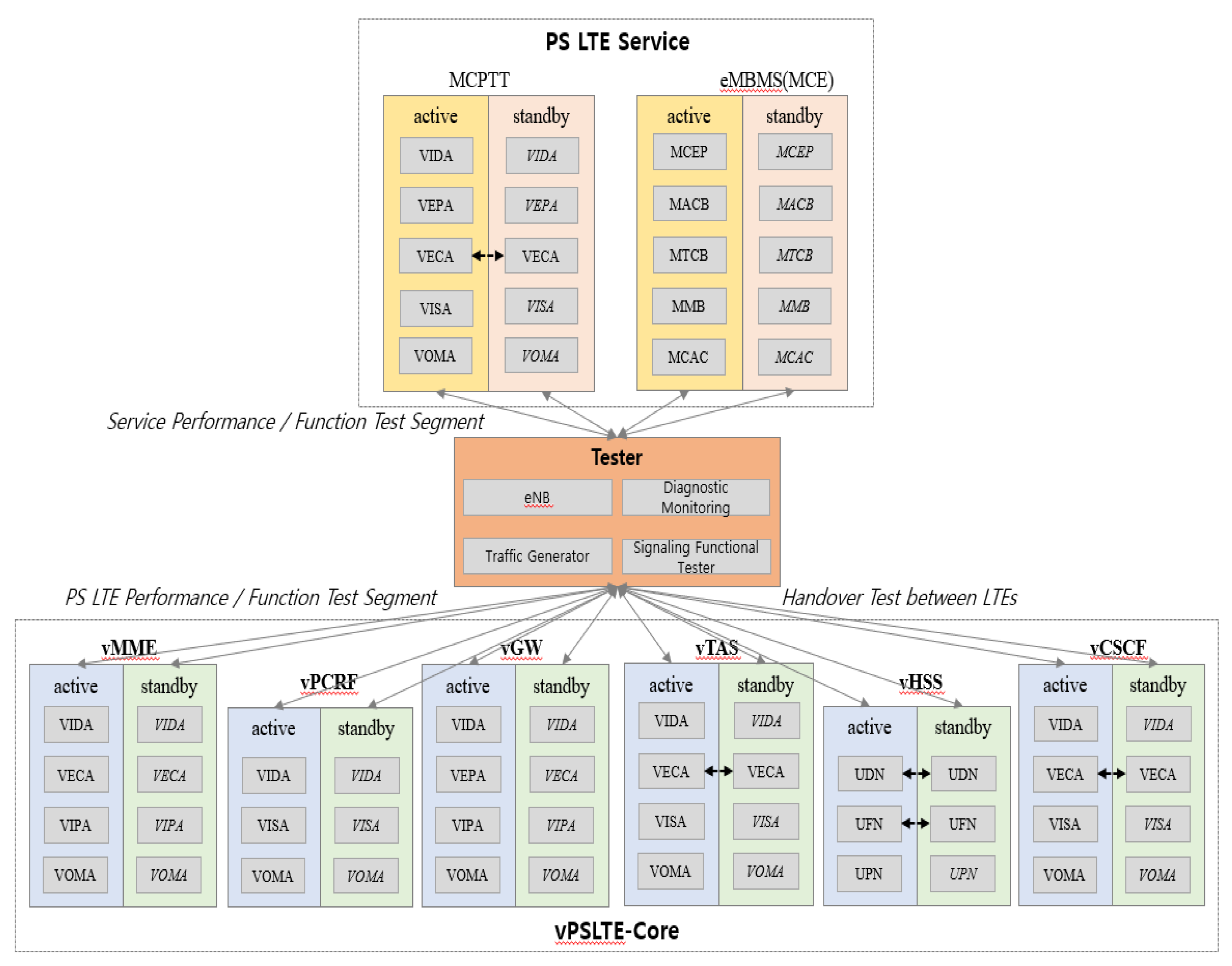
2.1. Core Equipment Test Environment

Core equipment comprises MCPTT, eMBMS, evolved packet core (EPC), RAN, sharing internetworking equipment, information management system (IMS), L3 switch, and others. As the core services of PS-LTE among the components above, the MCPTT entity performing the function of group communication for mission-critical services comprises common services core (CSC) servers, MCPTT servers, command servers, and command devices. Moreover, the eMBMS entity, which is an LTE-based mobile broadcasting technology for resolving call congestions, comprises a broadcast/multicast service center (BM-SC), multimedia broadcast and multicast service gateway (MBMS GW), and multicall/multicast coordination entity (MCE). Among the components of EPC, mobility management equipment (MME) is one of the network entities (NEs) that constitute the LTE core. It processes the mobility management and session management of the terminal; authentication of the terminal; handover control; control plane, which is connected to evolved node B (eNB); system architecture evolution gateway (SAE-GW); and home subscriber server (HSS) [12,13]. Core equipment must be tested for the required capacity and performance before establishment to smoothly perform the planned services. This paper proposes a performance test call model of MME and SAE-GW systems among core equipment for MCPTT which is a representative service of PS-LTE.
Figure 1 shows the composition of the core equipment, measuring instrument, and simulator environment for performance tests. The main VNF configuration as a component of core networks comprises (i) a virtual operation and management application (VOMA) for system operation maintenance, (ii) a virtual interface and protocol distribution application (VIPA) for stream control transmission protocol (SCTP)/diameter call distribution with connection with HSS/eNB, (iii) a virtually established call-processing application (VECA) for session-initiation protocol (SIP)/media gateway control (Megaco) call distribution and PTT call-processing functions, (iv) a virtual interface and distribution application (VIDA) for physical linking with external NE and Layer 4 (L4) load distribution, (v) a virtual interface of session application (VISA) for diameter/HTTP call distribution and subscriber/session information management, and (vi) a virtually established packet processing application (VEPA) for processing PTT media. The components of HSS comprise a UPN (user data convergence (UDC) proxy node) for connection with external NE and L4 load distribution, a UDC function node (UFN) for HSS call processing and connection with the MME/call session control function (CSCF)/MCPTT, and a UDC database node (UDN) for subscriber information database management. MCE is a nonvirtualized system and is installed as separate hardware and software configurations. MCE comprises MCE processing software for base station resource allocation, MCE access control block for session management, MCE transmission control block for SCTP connection management, MCE management block for eMBMS service area management, and MCE connection admission control for session admission load management. In PS-LTE systems, VECA, UDN, and UFN for important services operate in an active–active mode, and the rest of the configurations operate in an active–standby mode.

2.2. MCPTT Core System Test Model

The NE comprising MCPTT services consists of command devices, CSC servers, and MCPTT servers. Representative services are group voice/video calling and group character services, and for these services, the control plane is processed by linking with terminals, CSCF, and HSS. MCPTT is provided as a virtualization system, and the software structure comprises VOMA, VISA, VECA, VIDA, and VEPA. The requirements for the MCPTT system capacity in Korea are 480,000 busy hour register attempts (BHRA) for registering and 82.4 million busy hour call attempts (BHCA) for service.
Based on the above requirements, the load conditions of the simulator for MCPTT system testing approve full performance traffic according to the call model shown in Table 1. The conversion to Regi BHRA per subscriber is calculated by initial registration (INIT-REG) + refresh registration + deregistration (DE-REG). The conversion to service BHCA per subscriber is calculated as short message service (SMS) BHCA + MCPTT BHCA. As shown in Figure 2, the call operating conditions for instant message service (IMS) INIT-REG, DE-REG, and MCPTT voice/video/message simulator are as follows:
  • MCPTT voice outgoing call of 320,000 BHCA, incoming call of 320,000 BHCA, and 40,000 simultaneous-access call approvals (average holding time = 225 s);
  • MCPTT video outgoing call of 3.2 million BHCA, incoming call of 3.2 million BHCA, and 40,000 simultaneous call approvals (average holding time = 225 s);
  • MCPTT MSG of 200,000 BHCA and incoming of 200,000 BHCA call approvals;
  • MCPTT linkage of 240,000 BHRA INIT-REG and 240,000 BHRA DE-REG approval.
The operating condition according to the proposed call model processes is [INIT-REG (40,009) + DE-REG (40,005)] × 6 = 480,084 BHRA, which is repeated to perform the connection/disconnection of subscribers. The outgoing/incoming messages of the instant message (IM) are occurring as much as [originating participant function call session (OPFCS) (33,334: group outgoing call) + terminating participant function call session (TPFCS) (33,334: group incoming call)] × 6 = 400,008 BHCA. PTT voice/video call generation confirms [OPFCS (voice of 53,333 + videos of 5333) + TPFCS (voice of 53,335 + videos of 5339)] × 6 = 704,040 BHCA. Because the message load ratio per MCPTT 1 call is 0.3 compared to VoLTE, it is calculated as 400,008 × 0.3 = 120,002 BHCA, and the results of 700,400 BHCA + 120,002 BHCA = 824,002 BHCA are confirmed. As the test results are derived from the call model defined in Table 1, it can be confirmed that an appropriate call model was calculated, which can test the MCPTT service requirements of 82.4 million BHCA.

2.3. MME Core System Test Model

The MME for DSCNs is designed with a capacity of 400,000 simultaneous subscribers, and the detailed requirements for services are 3200 calls per second (CPS), 1,200,000 sessions (average of three sessions per subscriber), 2,400,000 bearers (average of six bearers per subscriber), 30,000 eNB, and 44,300 transactions per second (TPS). MME is installed as a virtual machine (VM) configuration on the two units of HP DL380, and it is provided as a virtualization system. In the performance test, the environment of the simulator and measuring instrument for each subsystem is set up, and the capacity and performance are measured by applying call connection/disconnection and voice/video call and general traffic to each subsystem. Because commercial measuring instruments do not support both user equipment (UE) and eNB, performance is measured using a self-developed simulator and a commercial packet generator for testing. System statistics confirm the number of subscribers, traffic, load, fail/drop and load status of CPU, and memory for each VM. It is assumed that 1 (subs):3 (session):6 (bearer) is created per subscriber. For a scenario for generating both 3200 CPS and 44,300 TPS, 370,000 fixed call subscribers are attached, and for 30,000 floating call subscribers, a scenario is created by attach → public data network (PDN) connectivity → X2 handover → tracking area update (TAU) → S1 release (S1REL) → scheduling request (SR) → PDN disconnect (PDN DISCON) → detach. As 16 tracking area codes (TAC) are assigned per tracking area list, the number of eNBs within 1 TAC is not limited. Terminal emulation for services was used for MCPTT group voice and video calls by 10 units, respectively, and for VoLTE voice and video calls, by two units.
Initial attach CPS means as the average (AVG) CPS × the number of transactions per attach. PDN connectivity CPS refers to total AVG CPS × the number of transactions per PDN connection (CON). X2HO Connectivity CPS is confirmed as total attempt/60 ch (CPS) × the number of transactions per PDN CON. TAU CPS refers to AVG CPS × the number of transactions per TAU. S1REL CPS transmits radio access bearer (RAB) request (REQ) message when S1REL occurs, and it is confirmed that total RAB REQ/60 ch (CPS) × the number of transactions per S1REL. SR CPS refers to total AVG CPS × the number of transactions per SR. PDN disconnect CPS is calculated as PDN disconnect = bearer deactivation per node (BDN)—DTACH and PDN DISCON CPS = BDN (attempt—DTACH attempt)/60. PDN DISCON TPS is calculated as PDN DISCON CPS × the number of transactions per SR. Detach TPS is calculated as AVG_CPS × the number of transactions per DTACH. Figure 3 shows the performance test results applying the call model set in Table 2, and it confirms the processing capacity of 48,807 TPS, which is higher than the requirement of 44,300 TPS. Therefore, the performance test is possible using the call model defined in Table 2.

2.4. SAE-GW Core System Test Model

SAE-GW is one of the NEs constituting LTE core and is integrated equipment in a serving gateway (S-GW) and a packet data network gateway (P-GW). The main functions of S-GW include inter-eNB handover, packet buffering, packet routing and forwarding, and transport-level packet marking. The main functions of P-GW include IP routing/forwarding, per-service data flow (SDF)/per-user-based packet filtering, IP address allocation to UE, and policy and charging control (PCC) rule processing. SAE-GW has an active–standby structure, and the interface comprises a small form-factor pluggable (SFP) + 12-port supporting 10-gigabit ethernet (GE) and RJ-45 8-port supporting 1 GE. The requirements for DSCNs are based on 400,000 subscribers, 16,000 TPS, and 10 Gbps (PCC on, deep packet inspection (DPI) on, row manager on). The call model for calculating the capacity and performance of SAE-GW is shown in Table 3.
The simulator load conditions for the SAE-GW test have used the fixed calls of 346,000 subscribers, floating calls of 10,000 subscribers, and traffic calls of 44,000 subscribers as inputs. Per subscriber, subscribers:session:bearer ratio (1:3:6) is calculated as 400,000 (subs):1,200,000 (session):2,400,000 (bearer). As for fixed-call subscribers, attach/PDN conn./bearer activation is performed. The simulator setting for floating call bulk subscribers is approved as 2400 CPS as a scenario of attach and detach, and attach/detach transaction is calculated as CPS × 7 (CSR, DSR, MBR, CCR-I, CCR-T, ACR_START, ACR_STOP), which is 16,800 TPS. As for UE traffic, traffic of 8 Gbps is applied to 44,000 subscribers, which is approximately 10% of 400,000 subscribers, using a commercial traffic generator, and the packet size is set by mixing 128, 512, and 1024 bytes. The total number of bearers is calculated as the number of fixed call bearers + the number of traffic call bearers, and the numbers of sessions and subscribers must be checked equally.
Figure 4 shows the test results applying the SAE-GW call model as shown in Table 3, and it can be seen that performance test is possible with the proposed call model by confirming the performance of 17,559 TPS and 16.9 Gbps (8.2 + 8.7 Gbps), which are higher than the requirements of 16,000 TPS and 10 Gbps.

2.5. Discussion

Since the disaster safety communication network is established by the telecommunication service providers and operated by the government agency, it is essential to conduct tests in accordance with the requirements from the initial construction stage. The performance test for core equipment of the disaster safety communication network has been required to define a new call model including the existing LTE service and MCPTT service. The MCPTT system capacity is 480,000 BHRA and 820,000 BHCA based on 400,000 subscribers, and the MME capacity is 3200 CPS and 44,300 TPS for 400,000 simultaneous subscribers. After testing the call model presented in Section 2 in a system with the same hardware/software version as the equipment built, it has been confirmed that the performance test was satisfactory. Therefore, the proposed call model can be used as a reference model for the performance tests of core equipment that must be considered when establishing a disaster safety communication network.
This paper proposed the call model and test methods in commercial PS-LTE, which have contributed to the world’s fastest commercialization and stable operation of a disaster safety communication network able to be utilized.

3. Field Test Scenarios for MCPTT and eMBMS

The MCPTT function is one of the most important functions among DSCN services, and ensuring stability for this function is important because it is an essential service to the field in case of various disasters. eMBMS is a service that can expand call capacity by switching to eMBMS when hundreds of people gather within a cell coverage during a rally or disaster situations, and DSCNs and call congestions occur through unicast communication.

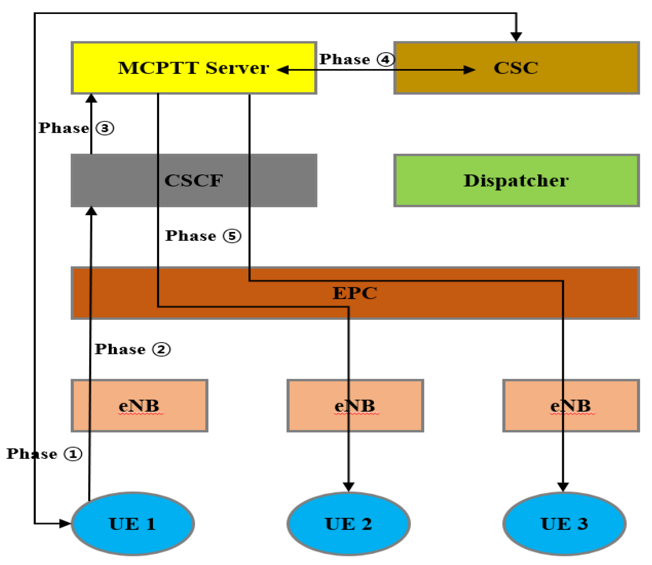
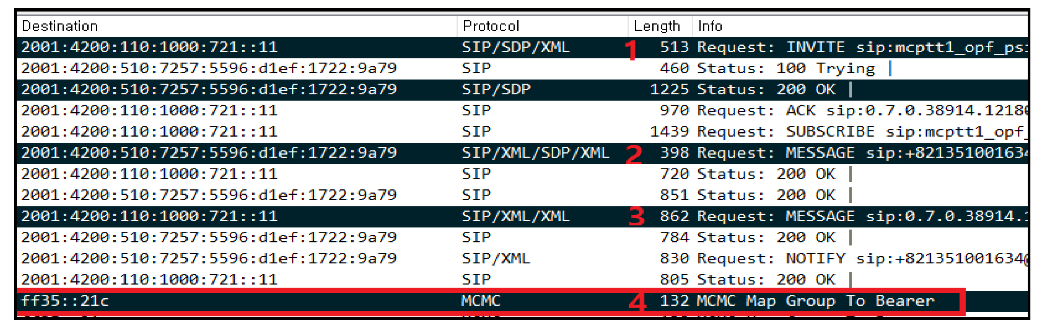
3.1. MCPTT Field-Test Scenarios

As for MCPTT test was performed such as group voice, group videos, all call paging, interception, emergency calls and multicall group reception functions. An MCPTT group call operates in a prearranged group call method in which command devices assign members to an affiliated group and call the group. Furthermore, as for floor control, if the push button is pressed, a request for permission to talk is sent to the floor control server, which sets in motion a mechanism for giving the right to transmit to the member with the highest priority among those who request permission to talk within a specific time [14,15]. According to the requirements for group calls, users select a call group by operating terminal buttons, switches, LCD panel touch, etc., and the terminals which are selected for a specific call group automatically receive all the calls of the corresponding call group. Only one user at a time is allowed to transmit to avoid collisions between transmission and reception during a group call. When a user is pressing the PTT button, it should be displayed as a separate pop-up to ensure that the user can selectively switch the reception mode without automatically disconnecting the group call [16,17]. Figure 5 shows an example concerning the creation of an MCPTT voice channel of the terminal for a group call, and it can be seen step-by-step as follows.
  • Step 1 (channel information inquiry): after an originating terminal performs the authentication procedure for a subscriber, it sends an inquiry to the CSC about the channel information under the subscriber’s management.
  • Step 2 (voice channel creation request): a request is made for the creation of a channel by transmitting a SIP:INVITE message containing the channel ID to the CSCF.
  • Step 3 (voice channel creation request): the CSCF forwards the message to the PTT server.
  • Step 4 (channel member inquiry): the MCPTT server acquires the member list of the corresponding channel from the CSC server.
  • Step 5 (voice channel participation request): the MCPTT server requests channel participation to the channel members by transmitting a SIP:INVITE message.
CSCF requests the application of quality of service (QoS) for voice channel through a policy and charging rule function (PCRF), and EPC (SAE-GW) and eNB are established by applying MCPTT voice QoS to the bearer for the voice channel. If the button for a group call is pressed from terminals included in a specific group, it is verified whether the voice or video call is maintained without being interrupted for 30 s in all the reception terminals within the group. As for interception, a terminal with a higher priority should be able to terminate an emergency call from a terminal with a low priority and should be able to preempt the right for transmission according to the priority levels preallocated to the terminals, including command devices, within the same group. During emergency calls within the same group, if another user with the same priority requests an emergency call, they are not allowed to preempt the right of transmission of the existing emergency call user. The reception function for a multicall group refers to an ability for one terminal to receive two or more call groups. In this case, the main call group should be able to transmit and receive, whereas the remaining subcall group is configured to only receive. To conduct tests, the PTT keys from a given pair of terminals, A1 and A2, are pressed simultaneously to verify if the respective main channels can communicate. Subsequently, the subchannel should be changed into the main channel to verify whether the call can be made in the same manner as before. As for the criteria for call connection tests, it should be confirmed whether the delay budget for each key performance indicator (KPI) is satisfied in the setup process for an MCPTT call presented in 3GPP TS 22.179 Release 13 [18].
  • KPI 1 restricts the required time to acquire permission to talk to within 300 ms.
  • KPI 2 restricts the end-to-end call connection time (invite to 200 OK) to within 1000 ms.
  • KPI 3 restricts the end-to-end media transmission delay time (mouth-to-ear latency) to within 300 ms when encryption is not applied.
The approximate delay of KPI 1 is calculated as approximately 200 ms using the network section from UE to peer entity through eNB, including (60 + 10 ms) × 2 (two-way delay) + UE L7 delay time (60 ms). The test is conducted at a fixed point of the wireless environment medium electric field, which does not include additional delays such as terminal mobility and RAN sharing. KPI 1, 2, and 3 should be measured for each terminal using a measuring instrument, and the average value is derived after repeating the process more than 50 times to ensure statistical significance of the result.
The test environment is shown in Figure 6, and groups are set for each manufacturer so that they are not affected by other groups during the test. Local selection calls that can call all the terminals within a specific area should not be operated during the test. The resulting measurements of delay budget in group voice calls are shown in Table 4, and it can be observed that the results of testing at a fixed point of reference at a signal received power (RSRP) of −63 dBm satisfies KPI 1/2/3.

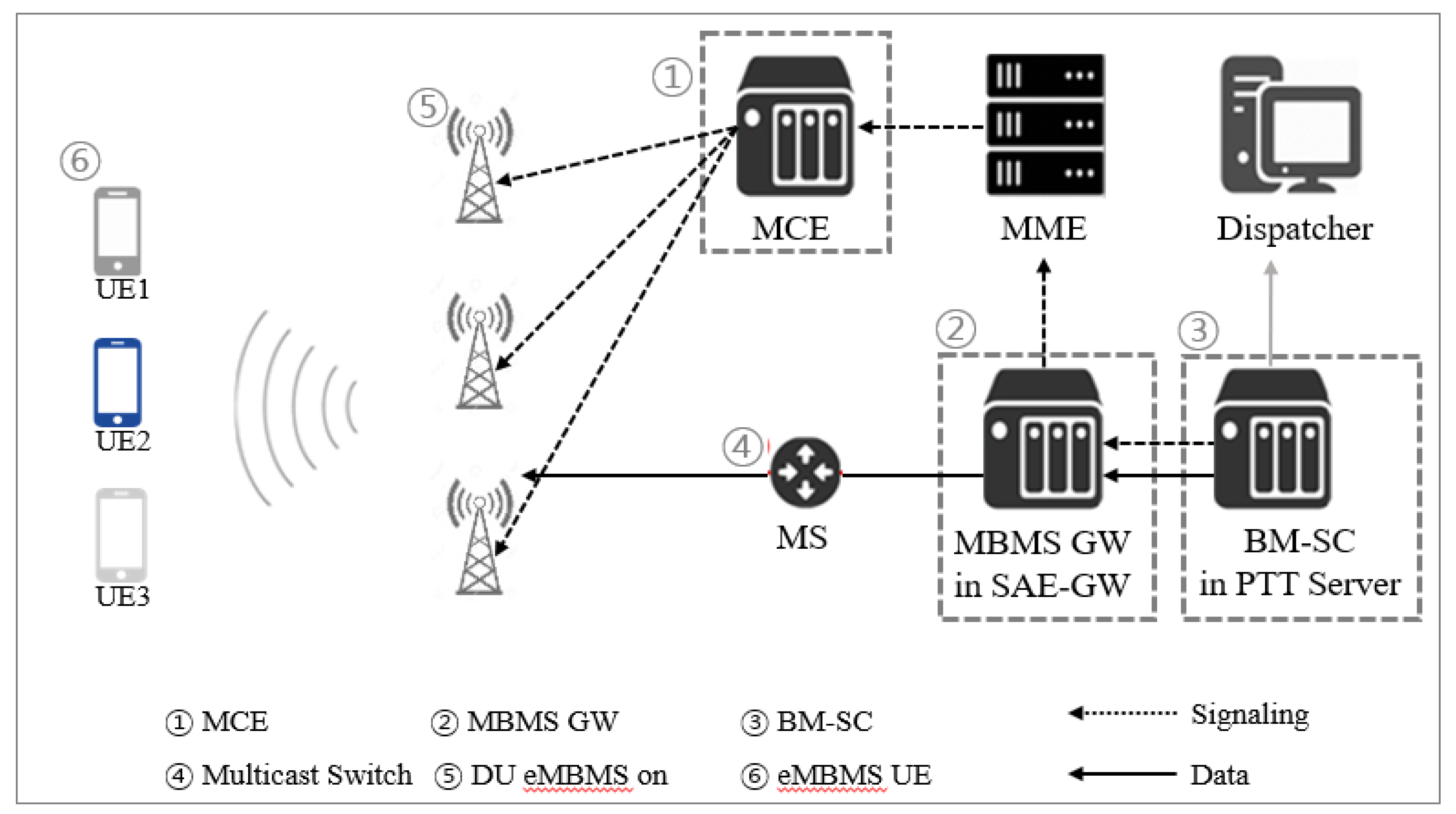
3.2. eMBMS Field Test Scenarios

The core component of eMBMS is multicast-broadcast single frequency network (MBSFN) transmission technology, which can simultaneously transmit the same data from different base stations. Multiple cells can be operated as one large cell using MBSFN technology by simultaneously transmitting the same data across multiple cells adjacent to each other. The set of cells that transmit the same data through the MBSFN transmission technology is called an MBSFN area, and several MBSFN areas are gathered to form an eMBMS service area. MBSFN areas can be configured up to 256, and each cell can be a component of up to 8 different MBSFN areas. Unicast-based MCPTT group calls should allocate as many bearer resources as the number of terminals, but eMBMS-based MCPTT group calls should allocate as many bearer resources as the number of groups [19,20]. The resource allocation of base stations for eMBMS services can freely switch between unicast and multicast methods, and DSCNs in the format of frequency division duplex can be allocated up to 60% of the resources. For group video and voice services per temporal mobile group identity (TMGI), 600 and 80 Kbps of resources are allocated, respectively, and TMGI has unique values for each eMBMS bearer, i.e., by group. Tests are performed on a total of 50 terminals: 15 from manufacturer A, 15 from manufacturer B, 10 from manufacturer C, and 10 from manufacturer D. For organizing MCPTT groups in command devices, unicast group (50 terminals) and multicast group (50 terminals) are organized, and the area code for MBMS is set. For setting the eMBMS service area, the MBSFN area (1 cell) is configured with a single unit of radio unit for the National Information Society Agency (NIA) testbed, and for the MBSFN area, it is configured with a separate MBMS service area and an MBSFN sync area. For the call group in which the terminals are organized, the service area is set up in the BM-SC, and the MBSFN and synchronization areas are set in the MCE and digital unit. The configuration diagram of the service networks for the eMBMS test is shown in Figure 7.
As shown in Figure 8, when MBMS service packets are analyzed, the MCPTT server that receives the message of MBMS listening status report should check the message (1–4 in Figure 8), which instructs the MCPTT client to use MBMS for receiving downlink data from the corresponding MCPTT service. Checking whether normal traffic is transmitted to multicast groups rather than unicast IP addresses is essential through the packet analysis of MBMS.
For the eMBMS, as the networks are established and the terminals are released without testing the service networks and terminal, user-based testing should be performed in an area receiving electric waves from DSCNs. Moreover, handover testing between the DSCNs and commercial networks should be performed to check whether unicast and multicast traffics are received normally. The multicast channel scheduling period of the terminals and service networks should also be checked in advance to prevent the situation of replacing hardware due to nonsupporting functions in the future.

3.3. Discussion

MCPTT and eMBMS functions are the core services of the disaster safety communication network. This paper describes various functions of the MCPTT and field test scenarios and results for KPI 1/2/3. In addition, the test configuration scenarios and detailed test results for eMBMS are explained with examples, and in the future, they can be used as reference data for testing in countries that have established disaster safety communication networks.

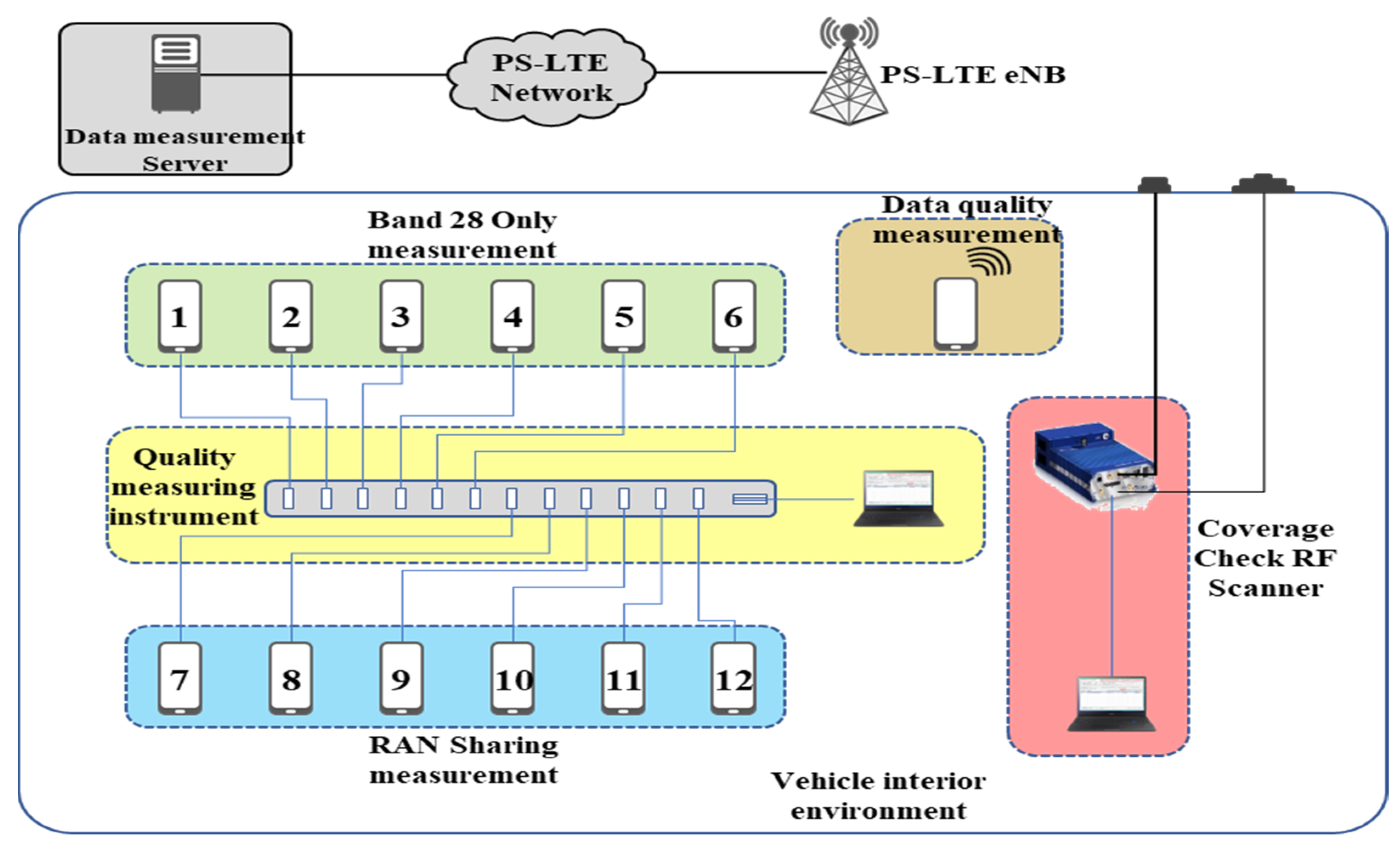
4. Measurement of Wireless Coverage and Quality

Korea’s DSCN project has a strategy to secure the target coverage by (i) establishing fixed base stations for national infrastructure, roads, and densely-populated areas; (ii) utilizing commercial networks for agricultural, fishery, and indoor/underground areas; and (iii) utilizing mobile base stations for mountainous areas. The coverage criteria for national infrastructure and government and public offices are the ground sections of national infrastructure designated according to the Framework Act on the Management of Disaster and Safety. Roads should give priority to service continuity, and in densely populated areas, the coverage range of fixed base stations includes residential, commercial, and industrial areas among the use areas according to the National Land Planning and Utilization Act. A mandatory coverage measurement test should be performed in the field to determine whether a single communications service infrastructure is properly established using four solutions (fixed base stations, commercial networks, mobile base stations, and LTE-based railway wireless communication system (LTE-R)/LTE-based maritime wireless communication (LTE-M)) [21]. Moreover, a quality test for call services should be conducted simultaneously with the coverage measurement. Preliminary testing of call services is required as many risk factors exist in using the newly established DSCNs immediately in various disaster situations. Areas that fall short of the criteria after the test should be retested after the optimization work of the communications business carriers.

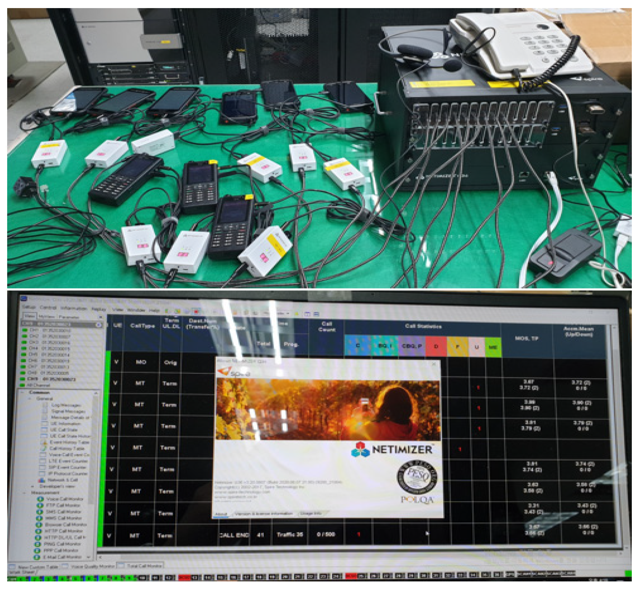
4.1. Measurement of Coverage and Call Quality

The purpose of coverage measurement is to provide stable services of DSCNs and to check the call rights necessary for immediate response in the event of a disaster. As for the coverage verification method, the RSRP value is measured at 75 × 75 grid units based on submunicipal administrative divisions, and RF scanners are used to verify whether an area is present whose RSRP drops below −117 dBm in the coverage edge. As for coverage measurements, RF scanners installed in vehicles measure RSRP values on roads that allow vehicle entry within the measurement area. The level of frequency for PS-LTE (700 MHz band) is measured in seconds using an RF scanner and stored together with GPS coordinates. To ensure a sufficient number of inspections (four or more) per grid, the inspection is conducted within 60 km/h, and if the average of RSRP is less than −117 dBm, it is judged as an area with insufficient coverage. The problem of the terminal itself should be minimized by selecting the manufacturer’s terminal with the most stable operation in DSCNs.
The terminal setting for the measurement is configured by dividing the terminals into those set up to communicate only via the PS-LTE (Band 28) frequency and those capable of RAN sharing. The composition of the terminals and measuring instruments for the coverage and quality of data/call tests is shown in Figure 9. For the measurement of coverage, the test should be conducted after the consultation of coverage paths for the target area so that the terminal can check the latest version of firmware and measure the signal strength for the target coverage proposed by the business carrier that built it.
Quality measurement is performed by composing a scenario in the order of individual call voice → individual call text → individual call video (set to record call video on the receiving terminal when measuring a video call) → voice group call → text group call → video group call. This scenario is repeated more than 20 times for measurement, and the composition of the measured call time for each call is shown in Table 5. Because 405 s are required for one measurement, approximately 135 min are required for 20 measurements [22,23].
Data are measured by repeatedly uploading and downloading files 30 times or more from the NIA diagnostic monitor app installed in the terminal. The time required for one measurement is 37 s, i.e., ping measurement (11 s), upload (13 s), and download (13 s). The measurement indicators based on the use stage of service for individual and group voice calls in standards such as ITU-T, ETSI, and 3GPP are shown in Table 6. [24,25].

4.2. Measurement of End-to-End Call Services

The measurement of end-to-end call services aims to confirm that smooth services are always provided for the areas where DSCNs have been established. For the end-to-end verification procedure, the measurement of voice, data, and video should be conducted for each service within a single base station, among multiple base stations, within heterogeneous network base stations, and between DSCN base stations and heterogeneous network base stations. For the measurement area, various types of verification areas and routes are selected for measuring end-to-end call services on the heterogeneous base stations (Samsung and Nokia) and heterogeneous networks (commercial, railway, and maritime networks). Moreover, the five major morphologies of national infrastructure, roads, densely populated areas, mountainous areas, and agricultural and fishery areas should be included by dividing downtown and suburban areas. For the measurement items, voice, data, and videos are measured for the following five types of call services according to call types.
  • For interception, only voice and data are measured, excluding voice transmission delay, voice quality, and data call connection measurement, while command devices and measuring instruments are not connected.
  • For individual calls, voice/data call connection time, call time, voice quality, data transmission time, and video quality are measured.
  • For group calls, voice/data call connection time, call time, voice transmission delay, voice quality, and data transmission time are measured, and the quality of group video is evaluated using the recorded video in the terminals.
  • For multiple call group receptions, call connection time and call time are measured, excluding delivery delay time and voice quality, because measuring instruments cannot confirm whether the terminal has succeeded in moving from call group A to B.
  • For multiuser full-duplex calls, call connection time and call time are measured, excluding voice quality, because measuring instruments cannot measure voice quality received in a mixed state of voices transmitted from several different terminals.
The vehicle environment of the terminal and measuring instrument for measuring end-to-end call services are shown in Figure 10.
Analysis of the measurement results of five end-to-end call services is as follows.
  • The success rate of text transmission is measured at 100%, and also measured are the completion rate of individual calls (voice—97%; video—97%), and the completion rate of group calls (voice—96%; video—99%).
  • Because the communication environment between a tunnel section (commercial networks) and a ground section (disaster networks) changes frequently, the policy of RAN sharing with commercial networks should be clearly defined.
  • As the radio resource control (RRC) connection release time is different for each business area, consultation among business operators is required; if no traffic is present in area A for 10 s, it transitions to the RRC_IDLE state due to the occurrence of RRC connection release.
  • Strengthening the examination of areas where DSCN services are weak is necessary, including the boundary area between disaster and commercial networks in mountainous areas, the boundary area between business operators, and the boundary area between regions (numerous call drops and network connection failures occur due to RAN-sharing failures).

4.3. Testing Mobile Base Stations

Mobile base stations provide coverage info through the main communication method in sparsely populated areas, such as mountainous areas and the open sea. Mobile base stations have a vehicle or a backpack type, and coverage inspection should measure frequency intensity (RSRP) while moving based on the coverage boundary provided in the mobile station equipment specification [23,26]. The test area should be selected for mountainous areas, urban areas (big-, small-, and medium-sized cities), and empty sites considering the diffraction, refraction, reflection, etc., of electric waves. Testing for data communication, voice, and video PTT functions should be conducted in terms of interoperability, call quality, and coverage through an efficient operation of mobile base stations and independent network configuration. Therefore, detailed test criteria of the mobile base station are shown in Table 7.
The test environment for mobile base stations (generic vehicle and generic portable types) is shown in Figure 11.

4.3.1. Coverage Test Results of Vehicle-Type Mobile Base Stations

The vehicle-type mobile base station (PCI: 500, antenna height of approximately 3 m) installed in the parking lot of the KT branch in Gangneung-si, Gangwon-do, has a low antenna height, which causes propagation loss due to neighboring buildings, and which is suitable to be used for traffic dispersion rather than securing coverage in urban areas. The coverage of the vehicle-type mobile base station is valid for up to 245 m in a straight-line distance. The portable mobile base station (PCI: 348, antenna height of approximately 1.5 m) also has a low antenna height and is blocked by neighboring buildings, and the output is also low; therefore, the portable mobile base station with a coverage of approximately 50 m is not suitable for use in urban areas.

4.3.2. Test Results of the Network Performance of Vehicle-Type Mobile Base Stations

The RAN-sharing test in the downtown area is conducted between fixed base stations ↔ mobile base stations, commercial network base stations ↔ mobile base stations, and maritime network base stations ↔ mobile base stations. Figure 12 shows that when the PS-LTE terminal is set to the RAN-sharing mode in the P2 area and moves among the other communication networks, the signal level of the serving cell decreases while the terminal is connected to the maritime networks (Band28, PCI 466); therefore, it is handed over to the commercial networks (Band3, PCI 469). Because handover occurs when the signal level of the serving cell is in the range of −117 dBm recommended by DSCNs, it satisfies the design value. The P1 section is a densely populated area with a large floating population due to Anmok Beach (Gangneung Cafe Street), which is a target coverage area for DSCNs. However, although it is located at a close distance of 1.7 km from the Songjeong-dong base station (PS-LTE) under the coverage shadow area of the DSCNs and call fails/drops occurs frequently, the signal level is very low (RSRP −100 to −120 dBm); thus, optimization is required to secure coverage.
Data transmission speed is measured in the downtown area where the PS-LTE mobile, fixed, marine network, and commercial network base stations are installed, centering on the KT Gangneung branch. For the download speed in Figure 13, although RSRP and signal-to-interference ratio (SINR) are good for the coverage section of the vehicle-type mobile base station (PCI 500) in the P1 section, the download speed is 0~1 Mbps, owing to the limit of the satellite backhaul bandwidth (2 Mbps). The download speed in the P2 section is 2~4 Mbps, owing to the SINR degradation caused by wave interference between PS-LTE and LTE-M. Although the P3 section is the coverage shadow section of PS-LTE and LTE-M (RSRP, −104 dBm and SINR, −1 dB), the download speed is measured at 6 Mbps, which is higher than in the area of the wave interference. Evidently, the resolution of the wave interference between PS-LTE and LTE-M should be considered a priority.

4.4. Summary and Analysis of Test Results

The summary and analysis of the test results of the coverage in disaster safety communication network and mobile base station are as follows:
  • The target of service area for disaster safety communication network is densely populated areas including national infrastructure and roads with two or more lanes. However, as a result of the coverage test, there are many areas share with commercial network due to the shaded sections; hence, it is necessary to improve and optimize the coverage.
  • As the area where the disaster safety communication network and LTE-R RAN Sharing are not applied is measured, the voice call quality of the disaster safety communication network service is very poor. Therefore, early interworking measures through consultation with involved organizations are required.
  • When measuring disaster safety communication network and LTE-M RAN-sharing, because there are many cases where the Physical Resource Block is not allocated and data cannot be transmitted at the transmission rate (DL, UL) 0 Mbps, it is necessary to check the RAN-sharing parameter and the system.
  • Due to the coverage shadow section between the disaster safety communication network and LTE-M and the instability of RAN sharing, poor voice call quality, such as call drops and call fails, occurs; hence, optimization work is needed to improve the coverage between public networks.
  • The overall voice call quality in the boundary area between different types is good. However, because of poor coverage in some areas and quality deterioration due to the base station, output abnormality occurs; hence, equipment inspection and coverage optimization are required.
As described above, many problems occur in interworking between public networks or heterogeneous networks in the initial stage of disaster safety communication network. Therefore, it is necessary to solve problems after performing that coverage of the entire area, end-to-end and mobile base stations test.

4.5. Discussion

This chapter presents detailed scenarios for voice call quality measurement for coverage and disaster safety communication network services and scenarios for end-to-end testing in the same environment as actual users. In addition, test items and results for mobile base stations used as main communication methods in mountains and maritime areas increase success rate for late-entry construction organizations.

5. Conclusions

This paper described the testing and verification methods that should accompany the establishment of DSCNs in Korea. For the performance test on the core equipment, a new call model and the field test method of MCPTT and eMBMS as the representative services of DSCNs were proposed. Our experience regarding unit equipment tests, interoperability tests, and coverage/quality measurements was discussed along with use cases to confirm whether the network was established to satisfy the requirements of the client organization. The call model required for testing PS-LTE and the testing methods for coverage/quality provided herein can help reduce trial and error for countries that establish DSCNs in the future. Therefore, we expect that the test methodology and know-how for wired and wireless networks in DSCNs, wireless coverage, and quality measurements will be utilized by countries establishing DSCNs in the future.
In addition, to consistently maintain and manage service quality in the process of operating the disaster safety communication network, research on methods to establish indicators for a Service Level Agreement and manage sensor traffics for Internet of Things services should be conducted in the future.

Author Contributions

Conceptualization, methodology, and validation, J.-J.L., P.-K.P. and B.-C.C.; investigation, data curation, and structure of the paper, J.-J.L., S.-W.K. and K.-D.N.; writing—original draft preparation, J.-J.L., P.-K.P., B.-C.C. and S.-W.K.; writing—review and editing, and supervision, W.-S.R. All authors have read and agreed to the published version of the manuscript.

Funding

This research received no external funding.

Acknowledgments

This work was supported by the Institute of Information & Communications Technology Planning & Evaluation (IITP) grant funded by the Korean Government (MSIT) (No. 2020-0-00349, Testing environment infrastructure of 5G infra equipment).

Conflicts of Interest

The authors declare no conflict of interest.

References

  1. 3GPP. Study on Architecture Enhancements to Support Group Communication System Enablers for LTE (GCSE_LTE). Available online: https://portal.3gpp.org/desktopmodules/Specifications/SpecificationDetails.aspx?specificationId=873 (accessed on 2 August 2012).
  2. 3GPP. Service Aspects and Requirements for Network Sharing. Available online: https://portal.3gpp.org/desktopmodules/Specifications/SpecificationDetails.aspx?specificationId=705 (accessed on 4 August 2012).
  3. 3GPP. Mission Critical Push To Talk (MCPTT) over LTE.; Stage 1. Available online: https://portal.3gpp.org/desktopmodules/Specifications/SpecificationDetails.aspx?specificationId=623 (accessed on 4 August 2012).
  4. 3GPP. Feasibility Study for Proximity Services (ProSe) (Release 12). Available online: https://portal.3gpp.org/desktopmodules/Specifications/SpecificationDetails.aspx?specificationId=653 (accessed on 5 August 2012).
  5. 3GPP. Evolved Universal Terrestrial Radio Access (E-UTRA) and Evolved Universal Terrestrial Radio Access Network (E-UTRAN); Overall Descriptions; Stage 2. Available online: https://portal.3gpp.org/desktopmodules/Specifications/SpecificationDetails.aspx?specificationId=2430 (accessed on 6 August 2012).
  6. NPSTC. 700MHz Public Safety Broadband Task Force Report and Recommendations; NPSTC: Ellsworth, ME, USA, 2009. [Google Scholar]
  7. FCC. Connecting America: The National Broadband Plan; Federal Communications Commission: Washington, DC, USA, 2010. [Google Scholar]
  8. Ghafoor, S.; Sutton, P.D.; Sreenan, C.J.; Brown, K.N. Cognitive radio for disaster response networks: Survey, potential, and challenges. IEEE Wirel. Commun. 2014, 21, 70–80. [Google Scholar] [CrossRef]
  9. Casoni, M.; Grazia, C.A.; Klapez, M.; Patriciello, N.; Amditis, A.; Sdongos, E. Integration of satellite and LTE for disaster recovery. IEEE Commun. Mag. 2015, 53, 47–53. [Google Scholar] [CrossRef]
  10. Kumbhar, A.; Koohifar, F.; Givenc, I.; Mueller, B. A survey on legacy and emerging technologies for public safety communications. IEEE Commun. Surv. Tutor. 2017, 19, 97–124. [Google Scholar] [CrossRef]
  11. Jarwan, A.; Sabbah, A.; Ibnkahla, M.; Issa, O. LTE-based public safety networks: A survey. IEEE Commun. Surv. Tutor. 2019, 21, 1165–1187. [Google Scholar] [CrossRef]
  12. Park, N.H.; Lee, S.K.; Lee, K.C.; Kim, D.J.; Kwon, D.S. Technical mode for national safety disaster communication network. Inf. Commun. Mag. 2014, 31, 12–18. [Google Scholar]
  13. Casoni, M.; Guo, S.; Benslimane, A. Emergency networks and future public safety systems. Wirel. Commun. Mob. Comput. 2019, 2019, 1647092. [Google Scholar] [CrossRef] [Green Version]
  14. Gebremariam, A.A.; Usman, M.; Bassoli, R.; Granelli, F. SoftPSN: Software-defined resource slicing for low-latency reliable public safety networks. Wirel. Commun. Mob. Comput. 2018, 2018, 7253283. [Google Scholar] [CrossRef] [Green Version]
  15. Mission Critical Push to Talk (MCPTT) over LTE. Available online: https://www.etsi.org/deliver/etsi_ts/122100_122199/122179/15.02.00_60/ts_122179v150200p.pdf (accessed on 13 August 2012).
  16. Kaleem, Z.; Chang, K. Public safety priority-based user association for load balancing and interference reduction in PS-LTE systems. IEEE Access 2016, 4, 9775–9785. [Google Scholar] [CrossRef]
  17. Deng, Z.; Liu, X.; Qu, Z.; Hou, C.; Si, W. Robust heading estimation for indoor pedestrian navigation using unconstrained smartphones. Wireless Communications and Mobile Computing. Wirel. Commun. Mob. Comput. 2018, 2018, 5607036. [Google Scholar] [CrossRef]
  18. Jo, S.-W.; Jang, J.H.; Yu, S.; Shim, W. A validation of field test results for LTE-maritime. IFAC-PapersOnLine 2018, 51, 153–158. [Google Scholar] [CrossRef]
  19. Feng, S.; Liu, C.; Shen, C.; Choi, H.-A.; Rouil, R.A. An effective and efficient dynamic embms multicast grouping scheduling algorithm in MBSFNs for public safety scenarios. IEEE Access 2020, 8, 105701–105712. [Google Scholar] [CrossRef] [PubMed]
  20. Kaliski, R.; Chou, C.-C.; Wei, H.-Y. Further enhanced multimedia broadcast/multicast service in LTE-advanced pro. IEEE Commun. Stand. Mag. 2019, 3, 44–51. [Google Scholar] [CrossRef]
  21. Chen, W.; Ahmad, I.; Chang, K. Co-channel interference management using eICIC/FeICIC with coordinated scheduling for the coexistence of PS-LTE and LTE-R networks. EURASIP J. Wirel. Commun. Netw. 2017, 2017, 2. [Google Scholar] [CrossRef] [Green Version]
  22. Duong, T.Q.; Hoang, L.N.; Bao, V.N.Q. On the performance of two-way amplify-and-forward relay networks. IEICE Trans. Commun. 2009, 92, 3957–3959. [Google Scholar] [CrossRef]
  23. ITU-T Recommendation G.722.2. Wideband Coding of Speech at Around 16kbts/s Using Adaptive Multi-Rate Wide-Band(AMR-WB); ITU-T: Paris, France, 2003.
  24. ITU-T Recommendation G.107. The E-Model: A Computational Model for Use in Transmission Planning; ITU-T: Paris, France, 2008.
  25. ITU-T G.107.1. Recommendation Wideband E-Model; ITU-T: Paris, France, 2011.
  26. Song, B.; Lim, K.; Lee, B.; Cho, D.; Lee, H.; Jang, J.; Chang, K. SMART-Navigation over Pilot LTE-maritime: Deployment and coexistence with PS-LTE. IEEE Commun. Mag. 2019, 57, 126–131. [Google Scholar] [CrossRef]
Figure 1. Block diagram of core equipment test environment.
Electronics 10 02513 g001
Figure 2. Operating condition of MCPTT simulator.
Electronics 10 02513 g002
Figure 3. Test results of MME.
Electronics 10 02513 g003
Figure 4. Test results of SAE-GW.
Electronics 10 02513 g004
Figure 5. Flow Diagram of Creating an MCPTT Channel.
Electronics 10 02513 g005
Figure 6. Test composition for KPI.
Electronics 10 02513 g006
Figure 7. Configuration diagram of eMBMS-based service network.
Electronics 10 02513 g007
Figure 8. Logs of eMBMS.
Electronics 10 02513 g008
Figure 9. Block diagram of measuring environment for coverage and quality.
Electronics 10 02513 g009
Figure 10. Measuring environment for end-to-end call services.
Electronics 10 02513 g010
Figure 11. Test environment for mobile base stations.
Electronics 10 02513 g011
Figure 12. Analysis of RAN sharing items.
Electronics 10 02513 g012
Figure 13. Download throughput map.
Electronics 10 02513 g013
Table 1. MCPTT call model: assuming 400,000 subscriber base.
ItemsBHCA/UserVoLTE 1 Call
Comparison
VoLTE 1 Call
Conversion to BHCA
RegistrationInitial registration (MCPTT basis)0.1 BHRA
Refresh registration (MCPTT basis)1 BHRA
Deregistration (MCPTT basis)0.1 BHRA
Service BHCASMS BHCA1 BHCA30%0.3 BHCA
MCPTT BHCA1.76 BHCA100%1.76 BHCA
Regi BHRA per subscriber1.2 BHRA
Service BHCA per subscriber2.06 BHCA
Regi BHRA based on 400,000 subscribers480,000 BHRA
Service BHCA based on 400,000 subscribers824,000 BHCA
Table 2. MME call model: assuming 400,000 subscriber base.
ItemsTypeNumber of TransactionsBHCA/UserTransactions per Hour
AttachINIT100.44
DetachDetach UE30.090.27
Detach NW10.040.04
PreservationeNB init S1 REL2.538.3395.83
Service
request
UE2.518.8847.2
NW337.76113.28
Session managementPDN connection40.632.52
PDN disconnection300
Bearer activation2.52.085.2
Bearer deactivation2.52.085.2
Tracking area updateNo change2.500
S-GW relocation4.500
MME/S-GW
relocation
90.10.9
Periodic TAU3.50.120.42
HandoverX235.0615.18
S111.50.11.15
S1AP pagingPAGING0.2536.84107.368
TPH per subscriber398.553 TPH
TPS per subscriber0.1107 TPS
TPS based on 400,000 subscribers44,283.67 TPS
Table 3. SAE-GW call model: assuming 400,000 subscriber base.
ItemsNumber of TransactionsBHCA/
Subscriber
Transactions per Hour
Attach/Detach70.533.71
TAUw/SGW relocation000
w/MME and SGW relocation10.10.1
No change000
Periodic TAU10.120.12
Bearer activation12.082.08
Bearer deactivation12.082.08
X2
handover
w/o SGW relocation15.065.06
w/SGW relocation100
S1
handover
w/MME relocation10.10.1
UE init request (idle → active)118.8818.88
UE init request (idle ← active)237.7675.52
S1 release (active → idle)138.3338.33
PDN connection/disconnection50.633.15
TPH per subscriber149.13
TPS per subscriber0.0414
TPS based on 400,000 subscribers16,570
Throughput (Kbps) per subscriber20.85
Throughput (Gbps) based on 400,000 subscribers8.34
Table 4. Test results of MCPTT for KPI 1/2/3.
ManufacturerServiceKPI 1 (ms)KPI 2 (ms)KPI 3 (ms)
AGroup voice23271170
B29331247
C27331263
D42402248
Table 5. Measured call time for each call.
ItemPrivate Currency (s)Group Calls (s)
VoiceTextVideoVoiceTextVideo
Idle time10510101010
Setup time201020303030
Traffic time651065301030
Total952595705070
Table 6. Verification indicators for individual/group voice calls.
IndicatorsDescription
Connection
success rate
The rate at which the connection is completed within a certain base time among the calls of a connection attempt.
Dropped call rateThe rate at which the call is cut off within a certain call time among the calls of a successful connection.
Voice qualityMeasurement on a five-point scale for quality deterioration between original and received voices.
(ITU-T P.862 PESQ or P.863 POLQA standard algorithm applied).
Call success rateCall rate of successful calls above MOS threshold among call attempts.
Table 7. Mobile base station test items.
CategoryTest ContentTest Criteria
ConvenienceThe ability to move the mobile base station quickly and provide immediate service in the field
-
Availability of self-organization network feature
-
Subscriber registration and group creation
-
Required time for service provision
-
Convenience of antenna installation and appropriateness of antenna type for each wireless environment
-
Expansion of call capacity
-
MCPTT function based on 3GPP Rel13
CoverageCoverage by wireless environmentEffective coverage measurement (downtown area, empty site, and mountainous areas)
InteroperabilityHandover testing (RAN sharing, etc.)
-
Mobile station (normal type) ↔ Fixed station (PS-LTE)
-
Mobile station (general type) ↔ other communication networks (commercial networks/LTE-R/LTE-M)
-
Availability of S1/X2 handover
-
Availability of intra/inter-RAT handover
-
Availability of idle mode mobility
-
Parameter applicability for RAN sharing (neighbor list, PLMN, etc.)
Call quality
-
Individual call quality (voice/video)
-
Group call quality (voice/video)
Call service based on quality verification indicators
Publisher’s Note: MDPI stays neutral with regard to jurisdictional claims in published maps and institutional affiliations.

