1. Introduction
Superconductivity is a phenomenon occurring in certain materials at low temperatures, characterized by the complete absence of electrical resistance and the damping of the interior magnetic field (Meissner effect). The superconductivity first discovered historically, commonly known as conventional superconductivity, manifests itself at very low temperatures, close to absolute zero. There are also other classes of materials called unconventional superconductors, whose properties are not explained by conventional theory. In particular, the class of cuprates (or high superconductors), discovered in 1986, exhibits superconducting properties at higher temperatures than conventional superconductors (the critical temperature of high superconductors can be greater than a factor of 10 compared to that of conventional superconductors).
In recent years, there has been growing interest in the study of microstrip patch antennas made from superconducting materials [
1,
2,
3]. This is because superconducting microstrip antennas have shown significant superiority over corresponding antennas fabricated with normal conductors in terms of low insertion loss and high gain due to their lower surface resistance. Also, because of lower losses in superconductors, a reduction in size of these antennas is another advantage in using high
superconductors.
Several techniques have been used to excite microstrip patch antennas. Among them, the excitation of a microstrip patch by a microstrip line through a slot cut into the ground plane of the antenna seems to be very promising [
4,
5]. The main advantage of this feeding technique is the reduction of the spurious radiation since the ground plane separates the patch and the feed-line [
6].
In this paper, we study the effect of the slot cut into the ground plane on the resonant frequency and the bandwidth of superconducting rectangular microstrip patch antenna. This subject has not been reported in the open literature; only results for the operating frequency have been given [
7,
8]. The theory proposed here is based on the moment method in conjunction with the resistive boundary condition.
2. Proposed Approach
2.1. Surface Impedance of the Superconducting Patch
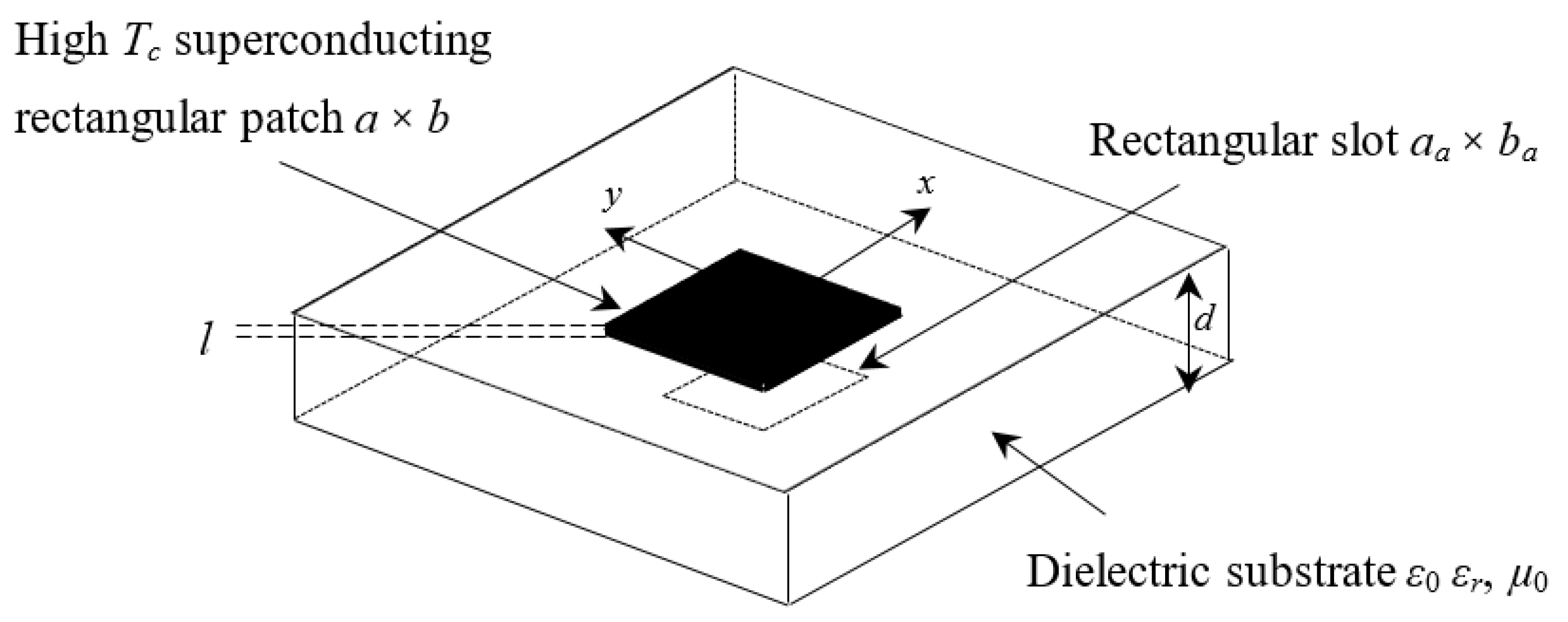
Considered here is a rectangular superconducting patch of thickness
and size
printed on a grounded dielectric slab of thickness
. The substrate material has a permeability
, and the permittivity is taken as
. Where
is the free-space permittivity and
is the relative permittivity. The superconducting patch is characterized by a critical temperature
, a penetration depth
at a zero temperature, and a normal state conductivity
. A rectangular slot of size
is cut into the ground plane (see
Figure 1). The tangential electric field in the plane of high
superconducting patch can be written as a superposition of an electric field in the patch
and another out of the patch
:
In the superconducting rectangular patch, the electric field may be written as follows:
In Equation (2),
denotes the complex surface impedance of the superconducting patch. If we consider that the thickness of the superconducting film is less than three times the zero temperature penetration depth,
can be approximated as [
2,
3]
In Equation (3),
represents the complex conductivity of the high
superconducting patch. It can be easily determined based on London’s equation and the Gorter-Casimir two-fluid model [
9]. Note that the resistive part of
comes from normal electron conduction, while its reactive part emanates from the motion of superconducting carriers.
2.2. Moment Method Procedure
If we denote by
and
(
and
) the spectral components of the tangential electric field at the plane of the patch (the ground plane), and by
and
(
and
) the spectral components of the current on the superconducting patch (the ground plane with slot), we can write based on the concept of dyadic Green’s functions the following two equations:
Substituting Equation (1) into Equation (4), we obtain the following result:
Replacing Equation (2) into Equation (6), we get
The system constituted of Equations (5) and (7) forms the integral equations for the case of superconducting microstrip antenna with a slot in the ground plane. Now, we can discretize Equations (5) and (7) using the moment method procedure. This procedure consists of the approximation of the current on the high
superconducting patch in terms of a set of known basis functions with unknown weights. Concerning the electric field at the slot, we will call on the concept of complementary electromagnetic structures. Using the moment method with weighting modes, chosen similar to the expansion modes, Equations (5) and (7) are reduced to a system of linear equations, which can be written in the following compact form [
10]:
In Equation (8), is the impedance matrix, and vector contains the unknown coefficients to be sought. A non-trivial solution of the system shown in Equation (8) requires that the determinant of the impedance matrix vanishes. The frequency corresponding to a zero determinant is called the resonant frequency. This is the frequency where the capacitive and inductive reactances cancel each other out. At this point, the antenna appears purely resistive, the resistance being a combination of the loss resistance and the radiation resistance. Note that the resonant frequency calculated herein is complex due to the radiation damping. Note that the imaginary part of the complex resonant frequency is a useful result since its value is used in the calculation of the half-power bandwidth and the quality factor.
Although the analysis presented in this paper concerns a superconducting patch printed on isotropic substrate, it is relatively simple to modify the proposed approach to account for the presence of anisotropy in the dielectric substrate. This can be done by replacing the dyadic Green’s functions in Equations (5) and (7) by corresponding functions including the anisotropy effect [
2]. Note that most of the practical substrates used in the design of microstrip antennas exhibit a significant amount of anisotropy that can affect the performances of these antennas, and thus, accurate characterization and design must account for the anisotropy effect.
Although, in this paper we have investigated a single-layer superconducting antenna; it is quite straightforward to extend the proposed approach to structures involving stratified substrates as well as stacked patches. Stacked patches are useful in situations where the antenna is required to operate efficiently at two distinct frequencies.
3. Validation of the Proposed Approach
The choice of basic functions in the moment method plays an important role in determining the rate of convergence. Inappropriate choice of these functions can lead not only to a slow convergence but also to erroneous results. In this paper, we have used an entire domain of sinusoidal form to approximate the unknown current density on the superconducting radiating element. Concerning the transverse electric field at the slot, we have used the concept of complementary electromagnetic structures.
In order to verify the accuracy of the proposed approach, our numerical results are compared with theoretical and experimental data available in the literature. In this comparison, we have considered structures with perfectly conducting patches. The physical and geometrical parameters of these structures are summarized in
Table 1.
Table 2 recapitulates our calculation of the resonant frequency and bandwidth as well as the data of the literature. For structures N°1 and N°4, the values of the literature are those measured experimentally [
11], while, for structures N°2 and N°3, the values of the literature are those obtained from the curve fitting results of Chew and Liu (Ref. [
12] for the real part of the resonant frequency and Ref. [
13] for the imaginary part of the resonant frequency).
Table 2 shows an excellent accordance between our numerical results and those of the literature for the four considered structures. The above comparisons allow us to validate the proposed approach developed in
Section 2.
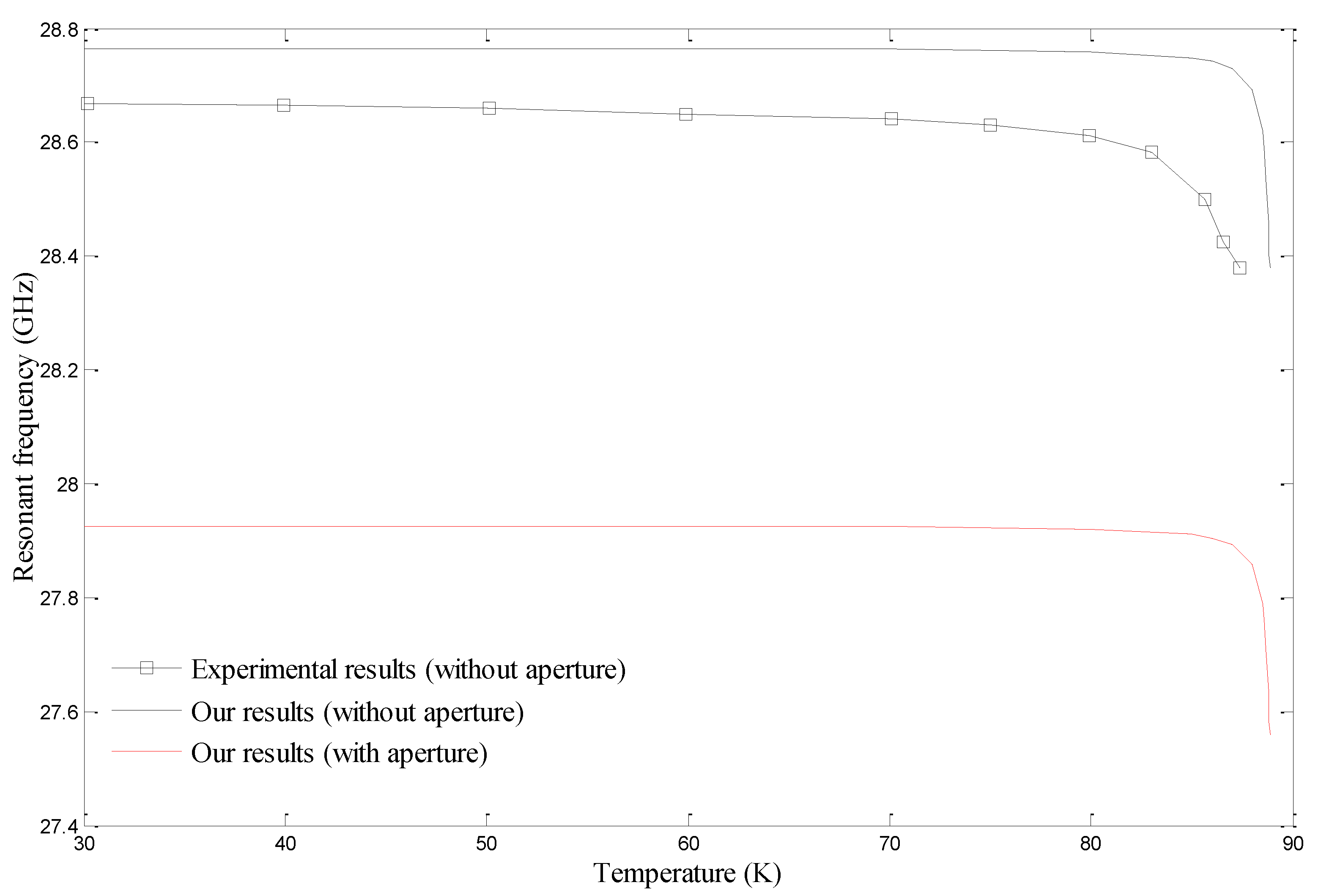
In
Figure 2, we study the influence of the operating temperature on the resonant frequency of superconducting antennas with and without aperture in the ground plane. For the case of antennas with apertures, the size of the aperture is
. The experimental measurements reported in [
14] are also included in this figure for comparison purposes. It is clear from
Figure 2 that our results are in good agreement with the experimental values. It is also seen from this figure that the effect of the operating temperature is significant especially for temperatures close to the transition temperature for antennas with apertures as well as for antennas without apertures in the ground plane.
4. Influence of the Area of the Slot on the Antenna Performances
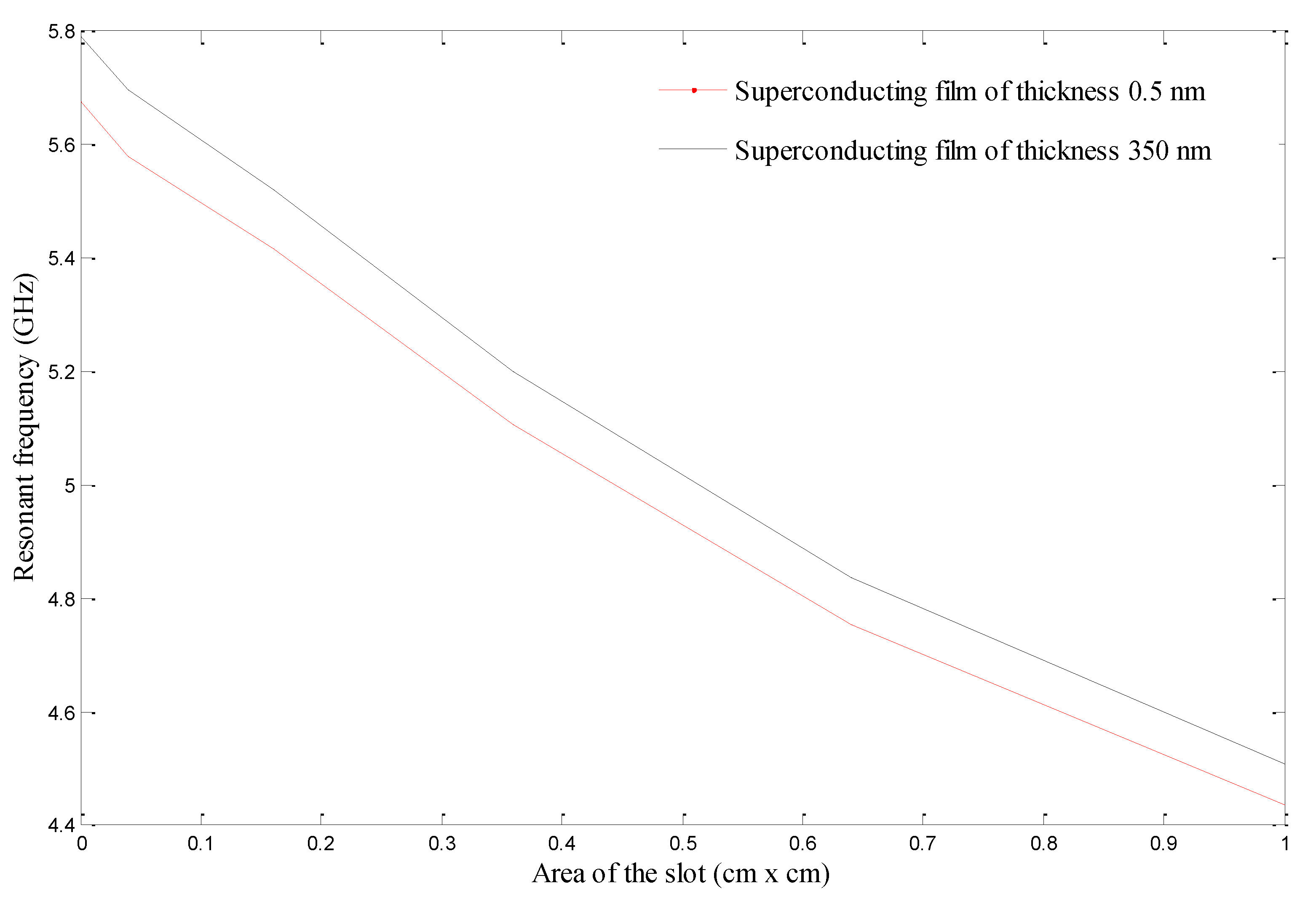
In
Figure 3, we study the influence of the surface of a slot of a square shape on the resonant frequency of high
superconducting rectangular patch. The patch is fabricated with YBCO superconducting thin film, having as parameters
,
and
. Two different thicknesses of the superconducting film are considered in
Figure 3. The square patch of size 1.4142 cm × 1.4142 cm is printed on Mylar substrate with
and
. The operating temperature is
. The results depicted in
Figure 3 indicate that the presence of a slot in the ground plane decreases the operating frequency of the high
superconducting antenna. This decrease is all the more important as the area of the slot is wider. This behavior is similar to that reported in [
11] for perfectly conducting patches. Indeed, when the size of the slot goes from zero to half of that of the patch with thickness
(
), the operating frequency of the antenna decreases from 5.791 GHz (5.677 GHz) to 4.508 GHz (4.436 GHz) for a fractional change of 22.15% (21.86%).
Concerning the effect of the square slot on the bandwidth of the superconducting antenna, we have reported the bandwidths for the different slots in
Table 3 for the case of superconducting film having a thickness of 350 nm and in
Table 4 for the case of superconducting film having a thickness of 0.5 nm. From the numerical results in the two tables, it is obvious that the broadest bandwidth is obtained for a slot with an area equal to half that of the high
superconducting patch. Therefore, in order to broaden the bandwidth of the superconducting antenna, it is strongly recommended to consider a ground plane with a slot having an area equal to half that of the superconducting rectangular patch.
Regarding the narrowest band, it is obtained when the area of the slot is equal to . Its value is 3.567% for the case of superconducting film having a thickness of 350 nm and 3.290% for the case of superconducting film having a thickness of 0.5 nm. Hence, it is strongly discouraged to use a slot having an area equal to in the design of this type of antenna.
5. Conclusions
In this paper, we have studied the electromagnetic characteristics of high
superconducting rectangular microstrip patch antenna having a slot cut into the ground plane. The analysis technique has been based on the moment method in conjunction with Gorter-Casimir two fluid model and London’s equations. The complex surface impedance has been calculated by supposing that the thickness of the high
superconducting film is less than three times the zero temperature penetration depth. The advantage of the proposed approach lies in its ability to give accurate results for thin as well as for thick substrates. This is because in our theoretical formulation, the surface wave effect has been rigorously included, unlike other approaches that provide physical approximations [
1]. It can also be easily extended to deal with superconducting patches of various regular and non-regular shapes printed on isotropic or anisotropic multilayered medium. The main disadvantage of the present approach is that its computational cost is relatively high due to the iterative nature of the solution process. In order to check the validity of the proposed approach, we have compared our numerical results against theoretical and experimental data available in the literature. We have shown that the presence of a slot with size equal to half of that of the superconducting patch results in a decrease of the operating frequency of more than 20%. Moreover, the broadest bandwidth has been obtained for a slot with an area equal to half that of the superconducting patch. Since superconducting microstrip antennas have high gain but suffer from narrow bandwidth, which severely limits their application [
15,
16], we believe that the latter result will be beneficial in overcoming this handicap. Finally, we draw attention to the fact that in the part of the numerical results, we have taken YBCO as a superconducting material. We have also obtained other numerical results using other superconducting materials. These superconducting materials are Bi
2Sr
2Ca
2Cu
3O
10 (BSCCO) and Tl
2Ba
2Ca
2Cu
3O
10 (TBCCO). For the sake of brevity, we have not reported these numerical results in this paper.
Author Contributions
Conceptualization, A.M., S.B., S.A. and T.A.D.; Methodology, A.M., S.B., S.A. and T.A.D.; Software, A.M.; Supervision, S.B., S.A. and T.A.D.; Validation, S.B.; Writing–original draft, A.M.; Writing–review & editing, A.M., S.B., S.A. and T.A.D. All authors have read and agreed to the published version of the manuscript.
Funding
This research received no external funding.
Conflicts of Interest
The authors declare no conflict of interest.
References
- Bedra, S.; Bedra, R.; Benkouda, S.; Fortaki, T. Efficient CAD model for the analysis of High Tc superconducting circular microstrip antenna on anisotropic substrates. Adv. Electromagn. 2017, 6, 40–45. [Google Scholar] [CrossRef][Green Version]
- Bedra, S.; Bedra, R.; Benkouda, S.; Fortaki, T. Superstrate loading effects on the resonant characteristics of high T c superconducting circular patch printed on anisotropic materials. Phys. C Supercond. 2017, 543, 1–7. [Google Scholar] [CrossRef]
- Bedra, S.; Bedra, R.; Benkouda, S.; Fortaki, T. Analysis of HTS circular patch antennas including radome effects. Int. J. Microw. Wirel. Technol. 2018, 10, 843–850. [Google Scholar] [CrossRef]
- Kumar, R.; Shinde, J.P.; Uplane, M.D. Effects of slots in ground plane and patch on microstrip antenna. Int. J. Recent Trends Eng. Res. 2009, 2, 34–36. [Google Scholar]
- Gupta, N. Effects of slots on microstrip patch antenna. Int. J. Eng. Technol. 2017, 4, 1132–1135. [Google Scholar]
- Bisht, S.; Saini, S.; Prakash, V.; Nautiyal, B. Study the various feeding techniques of microstrip antenna using design and simulation using CST microwave studio. Int. J. Adv. Res. Technol. 2014, 4, 318–324. [Google Scholar]
- Chebbara, F.; Benkouda, S.; Fortaki, T. Fourier transform domain analysis of high Tc superconducting rectangular microstrip patch over ground plane with rectangular aperture. J. Infrared Millim. Terahertz Waves 2010, 31, 821–832. [Google Scholar] [CrossRef]
- Boukhennoufa, N.; Djouane, L.; Oudira, H.; Amir, M.; Fortaki, T. Effect of the thickness of high Tc superconducting rectangular microstrip patch over ground plane with rectangular aperture. Int. J. Electr. Comput. Eng. 2018, 8, 1611–1617. [Google Scholar] [CrossRef]
- Benkouda, S.; Amir, M.; Fortaki, T.; Benghalia, A. Dual-frequency behaviour of stacked high Tc superconducting microstrip patches. J. Infrared Millim. Terahertz Waves 2011, 32, 1350–1366. [Google Scholar] [CrossRef]
- Bedra, S.; Bedra, R.; Benkouda, S.; Fortaki, T. Efficient full-wave analysis of inverted circular microstrip antenna. Microw. Opt. Technol. Lett. 2014, 56, 2422–2425. [Google Scholar] [CrossRef]
- Fortaki, T.; Khedrouche, D.; Bouttout, F.; Benghalia, A. Numerical analysis of rectangular microstrip patch over ground plane with rectangular aperture. Commun. Numer. Methods Eng. 2004, 20, 489–500. [Google Scholar] [CrossRef]
- Chew, W.C.; Liu, Q. Resonance frequency of a rectangular microstrip patch. IEEE Trans. Antennas Propag. 1988, 36, 1045–1056. [Google Scholar] [CrossRef]
- Chew, W.C.; Liu, Q. Correction to “Resonance frequency of a rectangular microstrip patch”. IEEE Trans. Antennas Propag. 1988, 36, 1827. [Google Scholar] [CrossRef]
- Richard, M.A.; Bhasin, K.B.; Claspy, P.C. Superconducting microstrip antennas: An experimental comparison of two feeding methods. IEEE Trans. Antennas Propag. 1993, 41, 967–974. [Google Scholar] [CrossRef]
- Benkouda, S.; Messai, A.; Amir, M.; Bedra, S.; Fortaki, T. Characteristics of a high Tc superconducting rectangular microstrip patch on uniaxially anisotropic substrate. Phys. C Supercond. 2014, 502, 70–75. [Google Scholar] [CrossRef]
- Boughrara, A.S.; Benkouda, S.; Bouraiou, A.; Fortaki, T. Study of stacked high Tc superconducting circular disc microstrip antenna in multilayered substrate containing isotropic and/or on uniaxial anisotropic materials. Adv. Electromagn. 2019, 8, 1–5. [Google Scholar] [CrossRef]
| Publisher’s Note: MDPI stays neutral with regard to jurisdictional claims in published maps and institutional affiliations. |
© 2021 by the authors. Licensee MDPI, Basel, Switzerland. This article is an open access article distributed under the terms and conditions of the Creative Commons Attribution (CC BY) license (http://creativecommons.org/licenses/by/4.0/).


