Experimental Parameter Tuning of a Portable Water Generator System Based on a Thermoelectric Cooler


Abstract
1. Introduction
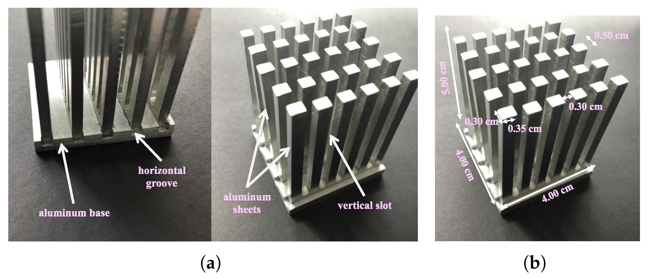
2. AWG Prototype
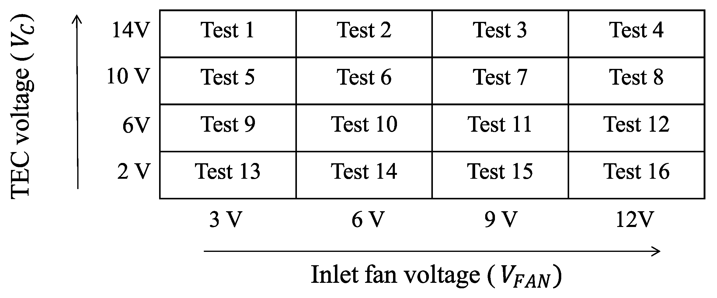
3. Description and Results of the Parameter Tuning Process
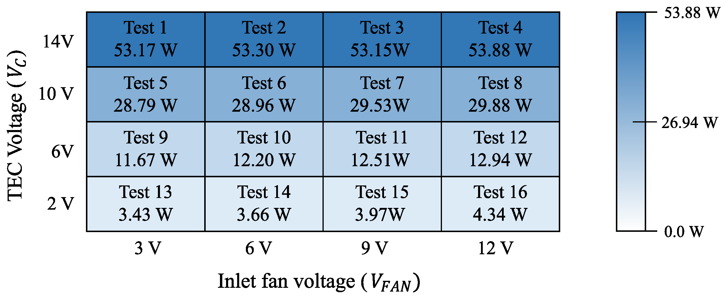
4. Parameter Tuning Analysis
5. Comparison of the Proposed PAWG with the SoA
6. Conclusions
Author Contributions
Funding
Institutional Review Board Statement
Informed Consent Statement
Data Availability Statement
Acknowledgments
Conflicts of Interest
Abbreviations
| AWG | Atmospheric Water Generator |
| PAWG | Portable Atmospheric Water Generator |
| CPU | Central Processing Unit |
| FoM | Figure of Merit |
| PWM | Pulse-Width Modulation |
| Relative Humidity | |
| TEC | Thermoelectric Cooler |
| SoA | State-of-the-Art |
| Std. dev. | Standard deviation |
References
- Tu, R.; Hwang, Y. Reviews of atmospheric water harvesting technologies. Energy 2020, 117630. [Google Scholar] [CrossRef]
- Martines, E.; Lira, L. Cálculo de la Temperatura de Punto de Rocío a Diferentes Valores de Presión; Simposio de Metrología: Santiago de Querétaro, Mexico, 2008; Volume 22. [Google Scholar]
- Lawrence, M.G. The relationship between relative humidity and the dewpoint temperature in moist air: A simple conversion and applications. Bull. Am. Meteorol. Soc. 2005, 86, 225–234. [Google Scholar] [CrossRef]
- Pereira, L.S.; Cordery, I.; Iacovides, I. Coping with Water Scarcity: Addressing the Challenges; Springer: Berlin/Heidelberg, Germany, 2009. [Google Scholar]
- Molden, D. Water for Food Water for Life: A Comprehensive Assessment of Water Management in Agriculture; Routledge: London, UK, 2013. [Google Scholar]
- Cerro, C. Developing solutions for dealing with water and food scarcity: Atmospheric water generator and urban farm tower. In Proceedings of the 2018 IEEE Advances in Science and Engineering Technology International Conferences (ASET), Abu Dhabi, UAE, 6 February–5 April 2018; pp. 1–6. [Google Scholar]
- Pontious, K.; Weidner, B.; Guerin, N.; Dates, A.; Pierrakos, O.; Altaii, K. Design of an atmospheric water generator: Harvesting water out of thin air. In Proceedings of the 2016 IEEE Systems and Information Engineering Design Symposium (SIEDS), Charlottesville, VA, USA, 29 April 2016; pp. 6–11. [Google Scholar]
- Sondergeld, A.; Wang, G.; Dutta, A. Modeling the Viability of a Refrigeration-Based Atmospheric Water Generator under the Present-Day Climate. In Proceedings of the 2019 IEEE Global Humanitarian Technology Conference (GHTC), Seattle, WA, USA, 17–20 October 2019; pp. 1–5. [Google Scholar] [CrossRef]
- Liu, S.; He, W.; Hu, D.; Lv, S.; Chen, D.; Wu, X.; Xu, F.; Li, S. Experimental analysis of a portable atmospheric water generator by thermoelectric cooling method. Energy Procedia 2017, 142, 1609–1614. [Google Scholar] [CrossRef]
- He, W.; Yu, P.; Hu, Z.; Lv, S.; Qin, M.; Yu, C. Experimental Study and Performance Analysis of a Portable Atmospheric Water Generator. Energies 2020, 13, 73. [Google Scholar] [CrossRef]
- Muñoz-García, M.; Moreda, G.; Raga-Arroyo, M.; Marín-González, O. Water harvesting for young trees using Peltier modules powered by photovoltaic solar energy. Comput. Electron. Agric. 2013, 93, 60–67. [Google Scholar] [CrossRef]
- Joshi, V.; Joshi, V.; Kothari, H.; Mahajan, M.; Chaudhari, M.; Sant, K. Experimental investigations on a portable fresh water generator using a thermoelectric cooler. Energy Procedia 2017, 109, 161–166. [Google Scholar] [CrossRef]
- Zhao, D.; Tan, G. A review of thermoelectric cooling: Materials, modeling and applications. Appl. Therm. Eng. 2014, 66, 15–24. [Google Scholar] [CrossRef]
- Shourideh, A.H.; Ajram, W.B.; Al Lami, J.; Haggag, S.; Mansouri, A. A comprehensive study of an atmospheric water generator using Peltier effect. Therm. Sci. Eng. Prog. 2018, 6, 14–26. [Google Scholar] [CrossRef]
- Vián, J.; Astrain, D.; Domınguez, M. Numerical modelling and a design of a thermoelectric dehumidifier. Appl. Therm. Eng. 2002, 22, 407–422. [Google Scholar] [CrossRef]
- Suryaningsih, S.; Nurhilal, O. Optimal design of an atmospheric water generator (AWG) based on thermo-electric cooler (TEC) for drought in rural area. In AIP Conference Proceedings; AIP Publishing LLC: Melville, NY, USA, 2016; Volume 1712, p. 030009. [Google Scholar]
- Casallas, I.; Paéz, C.; Fajardo, A. Recolección de Agua Líquida por Condensación de Humedad Atmosférica Usando el Efecto Peltier; Pontificia Universidad Javeriana: Bogota, Colombia, 2019. [Google Scholar]
- DC FANS—50 × 50 × 10 mm. Available online: http://www.wakefieldvette.com/Portals/0/DC%20Fans/DC%20FANS%20Wakefield%20Vette%20Data%20Sheet_rev%20A.pdf (accessed on 28 December 2020).
- Bench Multimeters, 45 Dual Display Multimeter. FLUKE. Available online: http://www.smart-inc.com.tw/uploads/root/fluke45.pdf (accessed on 28 December 2020).
- Type K Thermocouple. REOTEMP. Available online: https://www.thermocoupleinfo.com/type-k-thermocouple.htm (accessed on 28 December 2020).
- Calculating Thermocouple Measurement Error in DMM/Switch Temperature Measurement Systems. National Instruments. Available online: https://knowledge.ni.com/KnowledgeArticleDetails?id=kA03q000000x0dBCAQ&l=es-CO (accessed on 28 December 2020).
- NI USB-621x Specification. National Instruments. Available online: http://www.dept.aoe.vt.edu/~devenpor/aoe3054/manual/inst3/USB-6211.pdf (accessed on 28 December 2020).
- Duff, M.; Towey, J. Two Ways to Measure Temperature Using Thermocouples Feature Simplicity, Accuracy, and Flexibility. Analog Dialogue. 2010. Available online: https://www.analog.com/en/analog-dialogue/articles/measuring-temp-using-thermocouples.html (accessed on 28 December 2020).
- BME280, Combined Humidity and Pressure Sensor. BOSCH. Available online: https://www.bosch-sensortec.com/media/boschsensortec/downloads/datasheets/bst-bme280-ds002.pdf (accessed on 28 December 2020).


| Physical Variable | Test-Grid Axes | Type | Test-Grid Scale Relationship | |||
|---|---|---|---|---|---|---|
| (V) | X-axis | Experimental | 2.0 | 6.0 | 10.0 | 14.0 |
| (W/m) | X-axis | Calculated | 25.0 | 84.2 | 203.9 | 375.9 |
| (V) | Y-axis | Experimental | 3.0 | 6.0 | 9.0 | 12.0 |
| * (ft/min) | Y-axis | Estimated | 3.2 | 6.4 | 9.5 | 12.7 |
| Tests Number | (V) | (A) | (V) | (A) | (mL) | t (h) | Average (C) | Average (%) | Average e (C) | Average e (C) |
|---|---|---|---|---|---|---|---|---|---|---|
| 1 | 14.00 ± 0.0055 | 3.62 ± 0.0122 | 3.01 ± 0.0028 | 0.03 ± 0.00004 | 0.4 | 1 | 20.11 | 56.90 | 25.76 | −10.88 |
| 2 | 14.00 ± 0.0055 | 3.61 ± 0.0122 | 6.00 ± 0.0035 | 0.06 ± 0.00005 | 1.8 | 1 | 20.29 | 58.67 | 25.20 | −5.69 |
| 3 | 14.00 ± 0.0055 | 3.58 ± 0.0122 | 9.00 ± 0.0043 | 0.07 ± 0.00006 | 1.9 | 1 | 19.66 | 60.36 | 26.01 | −0.28 |
| 4 | 14.00 ± 0.0055 | 3.60 ± 0.0122 | 12.00 ± 0.0050 | 0.09 ± 0.00007 | 3.3 | 1 | 18.79 | 62.65 | 24.93 | 5.52 |
| 5 | 10.00 ± 0.0045 | 2.63 ± 0.0103 | 3.01 ± 0.0028 | 0.03 ± 0.00004 | 0.4 | 1 | 19.86 | 57.31 | 22.75 | −12.21 |
| 6 | 10.00 ± 0.0045 | 2.62 ± 0.0102 | 6.00 ± 0.0035 | 0.06 ± 0.00005 | 1.9 | 1 | 20.04 | 61.19 | 22.98 | −6.31 |
| 7 | 10.00 ± 0.0045 | 2.65 ± 0.0103 | 9.00 ± 0.0043 | 0.07 ± 0.00006 | 3.0 | 1 | 20.54 | 61.54 | 23.47 | −1.63 |
| 8 | 10.00 ± 0.0045 | 2.64 ± 0.0103 | 12.00 ± 0.0050 | 0.09 ± 0.00007 | 3.3 | 1 | 19.24 | 60.29 | 23.02 | 0.48 |
| 9 | 6.00 ± 0.0035 | 1.53 ± 0.0081 | 3.01 ± 0.0028 | 0.03 ± 0.00004 | 0.4 | 1 | 19.59 | 56.94 | 21.64 | −5.53 |
| 10 | 6.01 ± 0.0035 | 1.57 ± 0.0081 | 6.00 ± 0.0035 | 0.06 ± 0.00005 | 1.1 | 1 | 19.93 | 61.75 | 21.46 | −0.83 |
| 11 | 6.00 ± 0.0035 | 1.58 ± 0.0082 | 9.00 ± 0.0043 | 0.07 ± 0.00006 | 2.7 | 1 | 20.64 | 62.14 | 21.55 | 2.77 |
| 12 | 5.99 ± 0.0035 | 1.58 ± 0.0082 | 12.00 ± 0.0050 | 0.09 ± 0.00007 | 2.6 | 1 | 19.41 | 59.43 | 21.27 | 4.09 |
| 13 | 2.00 ± 0.0025 | 0.47 ± 0.0059 | 2.99 ± 0.0027 | 0.03 ± 0.00004 | 0.1 | 1 | 19.47 | 56.34 | 19.50 | 12.40 |
| 14 | 2.00 ± 0.0025 | 0.45 ± 0.0059 | 6.00 ± 0.0035 | 0.06 ± 0.00005 | 0.1 | 1 | 19.48 | 62.62 | 20.82 | 11.95 |
| 15 | 2.00 ± 0.0025 | 0.47 ± 0.0059 | 9.00 ± 0.0043 | 0.07 ± 0.00006 | 0.1 | 1 | 20.16 | 64.54 | 20.50 | 12.54 |
| 16 | 2.00 ± 0.0025 | 0.49 ± 0.0060 | 12.00 ± 0.0050 | 0.08 ± 0.00006 | 0.1 | 1 | 18.13 | 63.76 | 21.86 | 14.31 |
| Tests Number | (W) | (W) | (W) | (mL/h) | (mL/Wh) |
|---|---|---|---|---|---|
| 1 | 50.68 ± 0.1725 | 0.09 ± 0.0001 | 53.17 ± 0.1843 | 0.4 ± 0.1002 | 0.01 ± 0.0019 |
| 2 | 50.54 ± 0.1019 | 0.36 ± 0.0002 | 53.30 ± 0.1207 | 1.8 ± 0.1044 | 0.03 ± 0.0020 |
| 3 | 50.12 ± 0.1010 | 0.63 ± 0.0004 | 53.15 ± 0.1200 | 1.9 ± 0.1049 | 0.04 ± 0.0020 |
| 4 | 50.40 ± 0.1016 | 1.08 ± 0.0006 | 53.88 ± 0.1205 | 3.3 ± 0.1141 | 0.06 ± 0.0021 |
| 5 | 26.30 ± 0.0530 | 0.09 ± 0.0001 | 28.79 ± 0.0837 | 0.4 ± 0.1002 | 0.01 ± 0.0035 |
| 6 | 26.20 ± 0.0528 | 0.36 ± 0.0002 | 28.96 ± 0.0836 | 1.9 ± 0.1049 | 0.07 ± 0.0036 |
| 7 | 26.50 ± 0.0534 | 0.63 ± 0.0004 | 29.53 ± 0.0840 | 3.0 ± 0.1118 | 0.10 ± 0.0038 |
| 8 | 26.40 ± 0.0532 | 1.08 ± 0.0006 | 29.88 ± 0.0839 | 3.3 ± 0.1141 | 0.11 ± 0.0038 |
| 9 | 9.18 ± 0.0185 | 0.09 ± 0.0001 | 11.67 ± 0.0674 | 0.4 ± 0.1002 | 0.03 ± 0.0086 |
| 10 | 9.44 ± 0.0190 | 0.36 ± 0.0002 | 12.20 ± 0.0675 | 1.1 ± 0.1017 | 0.09 ± 0.0084 |
| 11 | 9.48 ± 0.0191 | 0.63 ± 0.0004 | 12.51 ± 0.0676 | 2.7 ± 0.1097 | 0.22 ± 0.0088 |
| 12 | 9.46 ± 0.0191 | 1.08 ± 0.0006 | 12.94 ± 0.0676 | 2.6 ± 0.1090 | 0.20 ± 0.0085 |
| 13 | 0.94 ± 0.0019 | 0.09 ± 0.0001 | 3.43 ± 0.0648 | 0.1 ± 0.1000 | 0.03 ± 0.0292 |
| 14 | 0.90 ± 0.0018 | 0.36 ± 0.0002 | 3.66 ± 0.0648 | 0.1 ± 0.1000 | 0.03 ± 0.0273 |
| 15 | 0.94 ± 0.0019 | 0.63 ± 0.0004 | 3.97 ± 0.0648 | 0.1 ± 0.1000 | 0.03 ± 0.0252 |
| 16 | 0.98 ± 0.0020 | 0.96 ± 0.0005 | 4.34 ± 0.0648 | 0.1 ± 0.1000 | 0.02 ± 0.0230 |
| Ref. | Publication Year | (C) | (%) | PAWG Size L × H × W (m) | PAWG Volume (m) | TEC Number | (W) | (mL/h) | (mL/Wh) |
|---|---|---|---|---|---|---|---|---|---|
| [12] | 2017 | 30.0 | 63.0 | 0.7 × 0.40 × 0.45 | 0.1260 | 10 | 135.0 | 5 | 0.04 |
| [11] | 2013 | 18.0 | 60.0 | unknown | unknown | 2 | 50.0 | 4 | 0.08 |
| [9,10] | 2017, 2020 | 24.3 | 67.8 | 0.46 × 0.14 × 0.15 | 0.0097 | 2 | 52.3 | 11.2 | 0.21 |
| This work (Test 11) | 2019 | 20.6 | 62.1 | 0.12 × 0.10 × 0.27 | 0.0032 | 1 | 12.5 | 2.7 | 0.22 |
| [15] | 2002 | 27.0 | 82.0 | 0.20 × 0.18 × 0.30 | 0.0108 | 3 | 100.0 | 40.3 | 0.40 |
| [16] | 2016 | 25.3 | 60.0 | 0.35 × 0.10 × 0.10 | 0.0035 | 2 | 65.5 | 27.9 | 0.43 |
| [14] | 2018 | 30.0 | 60.0 | 0.43 × 0.34 × 0.17 | 0.0249 | 4 | 60.0 | 30 | 0.50 |
Publisher’s Note: MDPI stays neutral with regard to jurisdictional claims in published maps and institutional affiliations. |
© 2021 by the authors. Licensee MDPI, Basel, Switzerland. This article is an open access article distributed under the terms and conditions of the Creative Commons Attribution (CC BY) license (http://creativecommons.org/licenses/by/4.0/).
Share and Cite
Casallas, I.; Pérez, M.; Fajardo, A.; Paez-Rueda, C.-I. Experimental Parameter Tuning of a Portable Water Generator System Based on a Thermoelectric Cooler. Electronics 2021, 10, 141. https://doi.org/10.3390/electronics10020141
Casallas I, Pérez M, Fajardo A, Paez-Rueda C-I. Experimental Parameter Tuning of a Portable Water Generator System Based on a Thermoelectric Cooler. Electronics. 2021; 10(2):141. https://doi.org/10.3390/electronics10020141
Chicago/Turabian StyleCasallas, Ingrid, Manuel Pérez, Arturo Fajardo, and Carlos-Ivan Paez-Rueda. 2021. "Experimental Parameter Tuning of a Portable Water Generator System Based on a Thermoelectric Cooler" Electronics 10, no. 2: 141. https://doi.org/10.3390/electronics10020141
APA StyleCasallas, I., Pérez, M., Fajardo, A., & Paez-Rueda, C.-I. (2021). Experimental Parameter Tuning of a Portable Water Generator System Based on a Thermoelectric Cooler. Electronics, 10(2), 141. https://doi.org/10.3390/electronics10020141