Abstract
In this paper, an ungrounded coplanar waveguide-based embedded resonator method for microwave substrate characterization was presented. The effective dielectric constant of the structure and the dielectric constant of microwave substrates can be calculated by the measured resonant frequency. The measured insertion losses at resonant frequencies and the 3 dB bandwidth can be used to determine the loaded and unloaded quality factors, including the dielectric quality factor which is related to dielectric loss tangent. The radiation loss and the extra length due to fringing effect caused by the open-end structure were taken into account to improve the extraction accuracy. The experimental unloaded quality factor of the proposed resonator at resonance order 1 reaches 211.3. The extracted dielectric constant and dielectric loss tangent of Taconic TLY at resonance order 1 are, respectively, 2.218 and , which are only 0.018 (relatively 0.82%) and (relatively 3.18%) deviations from the datasheet values, respectively. The proposed resonator method is especially suitable for dielectric characterization of newly developed materials with the difficulty of realizing metal via holes, in which case substrate-integrated-waveguide (SIW) resonator methods are not applicable. When comparing with microstrip resonator methods, the proposed method is of higher quality factor, and it is more reliable and economical as well.
1. Introduction
Printed circuit board (PCB) technology is widely applied in microwave frequency applications, and accurate dielectric information of used PCB substrates is essential for the development of microwave devices, as the performances of these devices are greatly affected by the dielectric properties of PCB substrates [1,2]. Here, dielectric information or property is typically denoted as the complex relative permittivity , which is defined as the ratio of the permittivity of a dielectric substrate to the permittivity of vacuum (). The complex relative permittivity contains a real part and an imaginary part: the dielectric constant (the real part of , also called relative permittivity, Dk) and the dielectric loss tangent (the ratio of the imaginary part to the real part, also called dissipation factor, Df), both of which are considered the most important parameters.
Over the years, various methods and techniques for extracting the dielectric characterization of microwave substrates have emerged in the literature. These measurement techniques can be divided into two main categories: transmission/reflection technique and resonator technique. The transmission/reflection technique is based on the transmission/reflection of electromagnetic waves passing through the tested substrates, and it could always provide broadband and continuous characteristics for the substrate materials, while the extraction accuracy is relatively low [3,4,5]. In contrast, the resonator technique is usually used for more accurate measurement, while it is limited to discrete frequency points [6,7,8].
Among the reported resonator techniques, the resonator method based on substrate-integrated-waveguide (SIW) structure is widely used, as it possesses the merits of high quality factor, low cost, and ease of fabrication [6,9,10,11,12]. However, it is not easy to measure enough frequency points in broadband with high extraction accuracy for conventional SIW-based resonator methods, and novel SIW resonator designs are relatively complicated [13]. With the development of information technology, dielectric substrates for microwave applications are not only limited to the commonly used PCBs, but are also some newly developed materials, including textiles, low-loss glasses, cyclic olefin copolymer, epoxy films, etc. [14,15,16,17,18]. SIW structure is a type of fully shielded transmission line which is compatible with standard PCB technology, while SIW-based resonator method is not appropriate to extract the dielectric properties of these newly developed materials due to processing issues. For instance, it is a big challenge to make metal via holes for these new materials. Therefore, it is more suitable to use other planar transmission lines, such as microstrip lines (MLs) or coplanar waveguides (CPWs), to measure the properties of these new dielectric substrates. Previous study shows that the resonator methods based on microstrip line structure are mainly quarter wavelength stub, half wavelength stub, and ring configurations, but with low quality factors, and the extraction accuracy needs to be improved [8,13,19,20].
Therefore, this work proposes an ungrounded coplanar waveguide (UGCPW) structure-based embedded resonator with high quality factor for microwave substrate characterization. The UGCPW structure is suitable for surface plating on new substrates, and the process can relieve the issues of high cost and difficulty in fabrication, as well as possible consistency errors of metal thickness and roughness due to multiple electroplating [5]. The proposed resonator with embedded resonance stub contributes to achieve high quality factor, due to a small current density concentrating on the embedded stub. Section 2 presents the proposed resonator method with theoretical analysis. Section 3 provides the design and experimental results of the fabricated resonators, and a conclusion is given in Section 4.
2. The Proposed Resonator Method with Theoretical Analysis
A UGCPW-based embedded resonator is fed by two microwave connectors, as shown in Figure 1. The signal line located in the centre consists of feeding lines at both ends and an open-end transmission stub with quarter wavelength embedded in the middle position. T-type and ring resonant structures based on microstrip lines for extracting the dielectric properties of microwave substrates were proposed in the literature [8,21], though these structures are not suitable for UGCPW transmission lines, as the centre conductor and ground plate of UGCPW are in the same plane. The spurline structure and embedded spurline structure described in [22] are applicable in designing UGCPW resonators, and the embedded structure was employed in this study, due to the fact that it can produce a frequency response with narrower stopband and higher quality factor [22]. Similar to the microstrip line-based T-shape resonator described in [8], the proposed embedded resonator based on UGCPW will also resonate at odd integer multiples of its quarter wavelength frequency. The relationship between the length of the resonant stub and the corresponding resonant frequency is as follows:
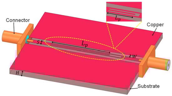
Figure 1.
Schematic diagram of the proposed ungrounded coplanar waveguide (UGCPW) embedded resonator.
From the above three formulas, we can get the following equation:
where and are the effective length and actual physical length of the resonant stub, respectively. is the extra length caused by the open-end structure, which effectively extends the physical length () of the resonator by an additional length () due to the fringing effect [19,23]. can be considered the correction of the actual physical length to the forming of resonance, and it could lead to more accurate results for the effective dielectric constant of the UGCPW-based structure and the dielectric constant of the PCB substrate. is the guided wavelength, is the order of the resonance (odd integer, ), is the velocity of light in free space, and is the resonant frequency.
2.1. The Calculation of Substrate Dielectric Constant
The extra length due to the open-end fringing effect could be approximated by the empirical equations as follows [23]:
where and are the widths of the feeding signal line and resonator stub line, respectively. is the substrate thickness. The relationship between and is expressed as follows [24]:
where is the filling factor, and it can be determined by the related equations described in [5]. It is noticeable that the calculation of is related to and (see Equations (5)–(11)), both of which are unknown, while the value of has to be derived through (see Equation (4)). Therefore, we introduced an estimated dielectric constant and an effective dielectric constant , and the initial value of can be calculated by the following equation:
The initial value of can be easily obtained by applying the equation above, when the resonant frequency is measured and actual physical length of the resonant stub is provided. In the next step we can get the estimated dielectric constant through Equation (12), then the actual and is able to be derived by using Equations (4) and (12) after calculating through Equations (5)–(11). It should be noted that the above calculation is only for the initial values of and , and the comparison and iteration method need to be applied to find the final and , which are equal to the final estimated values of and , respectively.
2.2. The Calculation of Substrate Dielectric Loss Tangent
After obtaining and , we can deduce the dielectric loss tangent of the PCB substrate. According to the measured resonant frequencies and the corresponding 3 dB bandwidth of the resonance peak (3 dB up), the loaded quality factor can be calculated:
where is the resonant frequency and is −3 dB bandwidth of the resonance peak. The loaded quality factor consists of the quality factor of the embedded resonator together with the external load caused by the measurement system. Furthermore, we can calculate the unloaded quality factor from and the insertion loss at the resonant frequency, which can be conducted by the following approximation in Equation (15). As the unload quality factor includes the effects from dielectric loss, conductor loss, and radiation loss of the embedded resonator, the dielectric quality factor can be obtained by Equation (16):
where and are the conductor quality factor and radiation quality factor, respectively. is the dielectric quality factor, which is related to the dielectric loss, so the dielectric loss tangent can be calculated by , as follows:
The conductor quality factor due to the conductor loss can be calculated as follows:
where and are the conductor loss and the guided wavelength in the UGCPW structure, respectively. The expressions of and are introduced in the following form, where is the distributed series resistance of the centre strip conductor in ohms per unit length, is the distributed series resistance of the ground planes in ohms per unit length, and is the characteristic impedance; the calculation methods of // are described in detail in [5].
Due to the bend, open-end, and T-junction discontinuous layout, the radiation losses of resonator-based configurations are usually much higher than that of straight-line configurations without discontinuities [8,25]. Radiation quality factor is often computed in many resonator-based configurations, many of which are microstrip line type [8,26,27]. The radiation quality factor due to the radiation loss can be calculated as follows:
where is the radiation loss of the UGCPW structure, and it can be computed by the following equation:
where is the gap between the feeding line and ground plane of UGCPW structure, and and are the complete elliptic integrals of the first kind that are related to the structure dimension [24]. The radiation form factor and dielectric wavelength are given by
In short, through the frequency response of the embedded resonator, and can be calculated first. The values of and can also be obtained from the UGCPW structure parameters, and then the dielectric quality factor can be derived by Equation (16). Finally, the value of substrate dielectric loss tangent is acquired through Equation (17). The algorithm proposed above is based on the quasi-transverse electromagnetic (TEM) approximation, and when the substrate thickness and structure linewidth are small enough, the quasi-TEM approximation can be maintained, where the effective dielectric constant would not show an obvious frequency dispersion at high frequencies [5,28]. In the quasi-TEM mode, the field is concentrated in the gaps between the UGCPW centre conductor and ground planes.
3. Experimental Results and Analysis
In order to evaluate the proposed method, we designed an embedded resonator with high quality factor based on ungrounded coplanar waveguide, where the substrate Taconic TLY is applied, and this substrate is considered to have the minimum dielectric loss tangent value. From the vender’s datasheet, the dielectric constant and dielectric loss tangent of Taconic TLY at 1 GHz are 2.2 and 0.0009, respectively. For the sake of reducing the manufacturing and measurement error, four samples were fabricated and measured to verify the reliability and consistency of the extraction method. Each resonator was fed by two Subminiature version A (SMA) connectors, and the frequency response of the two-port UGCPW resonator was measured using a Vector Network Analyzer (VNA), whose model is Agilent Technologies N5230A with a frequency range of 10 MHz to 20 GHz. To capture more accurate values of the scattering parameters (S-parameters), the applied VNA has to be calibrated through a Short-Open-Load-Through (SOLT) calibration technique with the help of calibration kit Agilent 85052D that contains the male and female short-open-load components. The SOLT calibration technique is also referred to as the Through-Open-Short-Match (TOSM) technique. The main dimension parameters of the UGCPW embedded resonator are listed as follows: signal feeding line width , gap , copper thickness , substrate thickness , and the physical length of the resonant stub is .
The measurement setup is shown in Figure 2. The resonant frequency, the corresponding insertion loss, and the 3 dB bandwidth of the resonator were measured by using a narrow frequency span to achieve sufficient frequency resolution for dielectric characterization. The simulation results of the embedded resonator and the measured frequency response of one embedded resonator sample are presented in Figure 3a,b, respectively. The obtained frequency responses were then processed by MATLAB software to extract other parameters, including the quality factors, dielectric constant, and dielectric loss tangent.
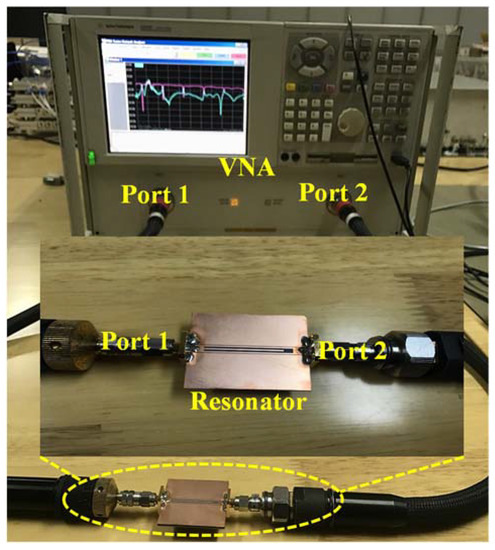
Figure 2.
Measurement setup with the fabricated UGCPW embedded resonator.
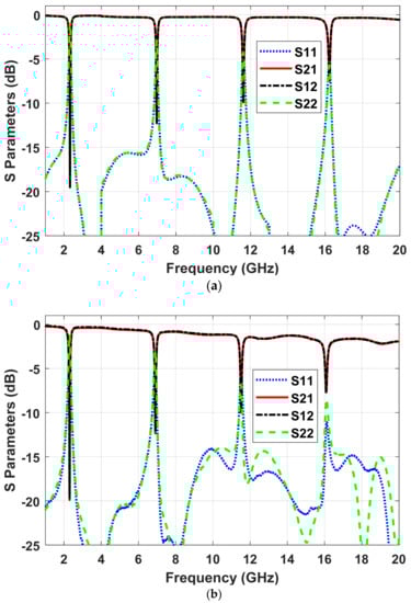
Figure 3.
(a) The simulated frequency response of the proposed embedded resonator and (b) the measured frequency response of one embedded resonator sample.
Table 1 lists the measured resonant frequencies and the corresponding insertion losses at these frequencies for the samples, as well as that of the simulation results for the proposed resonator. It proves that the proposed resonator resonates at odd integer multiples of its quarter wavelength frequency, as described in Equation (1). The data in this table also show that the frequency response measured by multiple samples is very close and has good consistency. It is also noticeable that the measured frequency responses are in good agreement with the simulation results. Based on the calculation method provided in Section 2.1, the extracted dielectric constant values of the samples at different resonant frequencies are set out in Figure 4, including their average dielectric constant at these frequencies. It can be seen from the figure that the dielectric constant values derived from the four samples have extremely small deviations at each resonant frequency. The average dielectric constants of the substrate at resonance order 1 (), order 3 (), order 5 (), and order 7 () are 2.218, 2.212, 2.212, and 2.227, respectively. The variations of the extracted dielectric constant of the four samples mainly come from the measurement, including the VNA noise, the cable stability, and the VNA calibration; all of these issues contribute to the difference of the measured S-parameters [29]. Another factor may be due to the fabrication tolerance, and it consists of the dimensional error and microwave connector repeatability of the samples. It can be observed from the extracted dielectric constant values that their differences are acceptable, and it can be reduced by averaging the values through multiple measurement. When comparing the dielectric constant ( at order 1 with that () given in the datasheet, the deviation of the dielectric constant value is only 0.018 (relatively 0.82%).

Table 1.
The resonant frequencies (Fre: GHz) and the corresponding insertion loss (IL: dB) at these frequencies for the selected 4 samples in measurement and simulation.
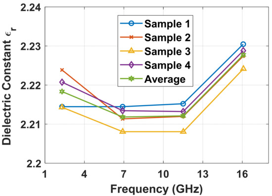
Figure 4.
The extracted dielectric constant values of the Taconic TLY samples.
By applying Equations (14) and (15) described in Section 2.2, the loaded () and unloaded () quality factors of the four samples at different resonant frequencies can be calculated, which are shown in Figure 5a,b, respectively. As can be seen from the figure, the average values of and at resonance order 1 (), order 3 (), order 5 (), and order 7 () are 209.1 and 211.3, 193.5 and 206.9, 188.7 and 212.1, and 125.4 and 155.5, respectively. The of the UGPCW embedded resonator at order 1 reaches 211.3, which is higher than those of microstrip line-based quarter-wave stub resonators, half-wave line resonators, and ring resonators in the literature [8,13,19,20]. For the proposed UGCPW embedded resonator, high current density is mainly concentrated on the line edges, and the current located in the central embedded resonator stub is small, which helps to achieve the high Q value.
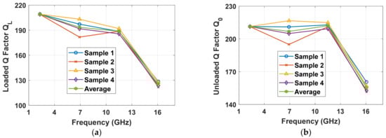
Figure 5.
(a) The loaded quality factors and (b) the unloaded quality factors of the selected four samples.
Figure 6a depicts the quality factors brought by various parts of sample 3, namely conductor quality factor , radiation quality factor , and dielectric quality factor . Based on the quality factors described in Figure 6a, the dielectric loss tangent values calculated from the loaded and unloaded quality factors are shown in Figure 6b, from which we can observe that using the unloaded quality factor to achieve reliable dielectric results is of great importance. In addition, the differences of dielectric loss tangent values calculated from and at higher frequencies are larger, indicating that the measurement accuracy is lower if is used for calculation.
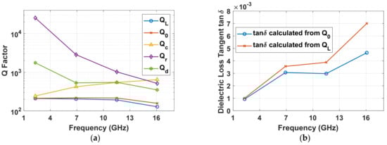
Figure 6.
(a) The various parts of quality factors (conductor quality factor , radiation quality factor , dielectric quality factor ) and (b) the difference of the dielectric loss tangent values when they are calculated from the loaded () and unloaded quality factors () for sample 3.
Figure 7 presents the derived dielectric loss tangent of these samples at various resonant frequencies. From the figure, we can see that the dielectric loss tangent increases slightly within the frequency range. The average of the substrate at resonance order 1 (), order 3 (), order 5 (), and order 7 () are , , , and , respectively. The dielectric loss tangent given on the datasheet at 1 GHz is 0.0009, while the measured value at order 1 () is , which means a small deviation of (relatively 3.18%) is observed. A comparison among different resonator-based methods for dielectric characterization is presented in Table 2, including the applied technique for property extraction (Tech.), the measured /, the extraction accuracy when comparing with reference values (/), the unloaded quality factor (), the working frequency (Fre.), and the processibility of the method (Proc.). It can be seen from the table that the proposed UGCPW embedded resonator method possesses very high extraction accuracy for deriving dielectric properties of microwave substrates, and the value of the unloaded quality factor is larger than that based on ML or CPW transmission line methods in the literature. Though SIW resonator method could achieve a higher quality factor and working frequency, it requires metal via operations on the substrate under test, which makes it not suitable for dielectric characterization of some newly developed materials with the difficulty of realizing metal via holes.
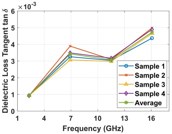
Figure 7.
The extracted dielectric loss tangent values of the Taconic TLY samples.
Table 2.
Comparison among different resonator-based methods for dielectric characterization.
4. Conclusions
This study has presented a UGCPW-based embedded resonant method with high quality factor to extract the dielectric properties of microwave substrates. The measurement results are in good agreement with the simulation, and the extracted dielectric constant and dielectric loss tangent show agreement within a single-digit percentage with the reference values provided by the substrate vender. The proposed method only needs one side copper plating, which could reduce the high fabrication cost and difficulties, as well as possible consistency error of metal thickness and roughness due to the multiple electroplating that occurs in ML resonator methods. Moreover, the method is especially appropriate to extract the dielectric parameters of newly developed substrates, which have difficulty realizing metal via holes.
Author Contributions
Conceptualization, methodology, software, validation, formal analysis, investigation, resources, data curation, writing—original draft preparation, writing—review and editing, visualization, supervision, project administration, funding acquisition, L.C. The author has read and agreed to the published version of the manuscript.
Funding
This research was funded in part by the National Natural Science Foundation of China (Grant No. 61901108), in part by the Natural Science Foundation of Jiangsu Province, China (Grant No. BK20180364), and in part by the National Key Research and Development Program of China (Grant No. 2019YFB2204704).
Institutional Review Board Statement
Not applicable.
Informed Consent Statement
Not applicable.
Data Availability Statement
Data sharing not applicable. No new data were created or analyzed in this study. Data sharing is not applicable to this article.
Acknowledgments
The authors thank the anonymous reviewers for the constructive comments and suggestions.
Conflicts of Interest
The authors declare no conflict of interest.
Nomenclature
| complex relative permittivity | |
| substrate dielectric constant, or substrate relative permittivity | |
| effective dielectric constant of UGCPW-based structure | |
| estimated dielectric constant | |
| estimated effective dielectric constant of UGCPW-based structure | |
| substrate dielectric loss tangent, or substrate dissipation factor | |
| effective length of resonant stub | |
| actual physical length of resonant stub | |
| extra length due to open-end fringing effect | |
| guided wavelength | |
| dielectric wavelength | |
| order of the resonance (odd integer, ) | |
| velocity of light in free space | |
| resonant frequency | |
| widths of feeding signal line | |
| widths of resonator stub line | |
| substrate thickness | |
| gap between the feeding line and ground plane of UGCPW structure | |
| filling factor | |
| distributed series resistance of centre strip conductor in ohms per unit length | |
| distributed series resistance of ground planes in ohms per unit length | |
| characteristic impedance | |
| −3 dB bandwidth of resonance peak | |
| insertion loss at the resonant frequency | |
| loaded quality factor | |
| unloaded quality factor | |
| conductor quality factor | |
| radiation quality factor | |
| dielectric quality factor | |
| conductor loss | |
| radiation loss | |
| radiation form factor |
References
- Wang, W.; Chen, Y.; Yang, S.; Cao, Q.; Li, H.; Zheng, X.; Wang, Y. Wireless inter/intra-chip communication using an innovative PCB channel bounded by a metamaterial absorber. IEEE Antennas Wirel. Propag. Lett. 2016, 15, 1634–1637. [Google Scholar] [CrossRef]
- Rautio, J.C.; Carlson, R.L.; Rautio, B.J.; Arvas, S. Shielded dual-mode microstrip resonator measurement of uniaxial anisotropy. IEEE Trans. Microw. Theory Tech. 2011, 59, 748–754. [Google Scholar] [CrossRef]
- Takach, A.A.; Moukanda, F.M.; Ndagijimana, F.; Al-Husseini, M.; Jomaah, J. Two-Line Technique for Dielectric Material Characterization with Application in 3D-Printing Filament Electrical Parameters Extraction. Prog. Electromagn. Res. 2019, 85, 195–207. [Google Scholar] [CrossRef]
- Chen, L.-F.; Ong, C.K.; Neo, C.P.; Varadan, V.V.; Varadan, V.K. Microwave Electronics: Measurement and Materials Characterization; John Wiley & Sons: Hoboken, NJ, USA, 2004; ISBN 0470020458. [Google Scholar]
- Cai, L.; Jiang, Z.H.; Huang, Y.; Hong, W. Ungrounded Coplanar Waveguide Based Straight Line Methods for Broadband and Continuous Dielectric Characterization of Microwave Substrates. IEEE Access 2020, 8, 32624–32631. [Google Scholar] [CrossRef]
- Zelenchuk, D.E.; Fusco, V.; Goussetis, G.; Mendez, A.; Linton, D. Millimeter-wave printed circuit board characterization using substrate integrated waveguide resonators. IEEE Trans. Microw. Theory Tech. 2012, 60, 3300–3308. [Google Scholar] [CrossRef]
- Zhu, X.-C.; Hong, W.; Zhang, P.-P.; Hao, Z.-C.; Tang, H.-J.; Gong, K.; Chen, J.-X.; Wu, K. Extraction of dielectric and rough conductor loss of printed circuit board using differential method at microwave frequencies. IEEE Trans. Microw. Theory Tech. 2014, 63, 494–503. [Google Scholar] [CrossRef]
- Latti, K.P.; Kettunen, M.; Strom, J.P.; Silventoinen, P. A Review of Microstrip T-Resonator Method in Determining the Dielectric Properties of Printed Circuit Board Materials. Instrum. Meas. IEEE Trans. 2007, 56, 1845–1850. [Google Scholar] [CrossRef]
- Wang, H.B.; Cheng, Y.J. Frequency selective surface with miniaturized elements based on quarter-mode substrate integrated waveguide cavity with two poles. IEEE Trans. Antennas Propag. 2015, 64, 914–922. [Google Scholar] [CrossRef]
- Cheng, Y.M.; Chen, P.; Hong, W.; Djerafi, T.; Wu, K. Substrate-integrated-waveguide beamforming networks and multibeam antenna arrays for low-cost satellite and mobile systems. IEEE Antennas Propag. Mag. 2011, 53, 18–30. [Google Scholar] [CrossRef]
- Cheng, Y.J.; Xu, H.; Ma, D.; Wu, J.; Wang, L.; Fan, Y. Millimeter-wave shaped-beam substrate integrated conformal array antenna. IEEE Trans. Antennas Propag. 2013, 61, 4558–4566. [Google Scholar] [CrossRef]
- Saeed, K.; Pollard, R.D.; Hunter, I.C. Substrate integrated waveguide cavity resonators for complex permittivity characterization of materials. IEEE Trans. Microw. Theory Tech. 2008, 56, 2340–2347. [Google Scholar] [CrossRef]
- Wang, H.B.; Cheng, Y.J. Broadband printed-circuit-board characterization using multimode substrate-integrated-waveguide resonator. IEEE Trans. Microw. Theory Tech. 2017, 65, 2145–2152. [Google Scholar] [CrossRef]
- Ghalichechian, N.; Sertel, K. Permittivity and Loss Characterization of SU-8 Films for mmW and Terahertz Applications. IEEE Antennas Wirel. Propag. Lett. 2015, 14, 723–726. [Google Scholar] [CrossRef]
- Seckin, S.; Nahar, N.K.; Kubilay, S. Permittivity and Loss Characterization of SUEX Epoxy Films for mmW and THz Applications. IEEE Trans. Terahertz Sci. Technol. 2018, 8, 397–402. [Google Scholar]
- Cai, L.; Jiang, Z.; Hong, W. Low-loss Substrate Material for Millimeter-wave and THz Applications. In Proceedings of the 2019 IEEE International Symposium on Radio-Frequency Integration Technology (RFIT), Nanjing, China, 28–30 August 2019; pp. 1–3. [Google Scholar]
- Kumar, R.; Kumar, P.; Gupta, N.; Dubey, R. Experimental investigations of wearable antenna on flexible perforated plastic substrate. Microw. Opt. Technol. Lett. 2017, 59, 265–270. [Google Scholar] [CrossRef]
- Declercq, F.; Rogier, H.; Hertleer, C. Permittivity and Loss Tangent Characterization for Garment Antennas Based on a New Matrix-Pencil Two-Line Method. IEEE Trans. Antennas Propag. 2008, 56, 2548–2554. [Google Scholar] [CrossRef]
- Carroll, J.; Li, M.; Chang, K. New technique to measure transmission line attenuation. IEEE Trans. Microw. Theory Tech. 1995, 43, 219–222. [Google Scholar] [CrossRef]
- Heinola, J.M.; Latti, K.P.; Strom, J.P.; Kettunen, M.; Silventoinen, P. A strip line ring resonator method for determination of dielectric properties of printed circuit board material in function of frequency. In Proceedings of the 17th Annual Meeting of the IEEE Lasers and Electro-Optics Society (LEOS), Boulder, CO, USA, 20 October 2004; pp. 692–695. [Google Scholar]
- Heinola, J.-M.; Latti, K.-P.; Silventoinen, P.; Strom, J.-P.; Kettunen, M. A new method to measure dielectric constant and dissipation factor of printed circuit board laminate material in function of temperature and frequency. In Proceedings of the 9th International Symposium on Advanced Packaging Materials: Processes, Properties and Interfaces (IEEE Cat. No. 04TH8742) 2004 Proceedings, Atlanta, GA, USA, 24–26 March 2004; pp. 235–240. [Google Scholar]
- Cai, L.; Chu, D. Highly anisotropic LC material with low dielectric loss for the application of tunable notch filters. J. Electromagn. Waves Appl. 2019, 33, 1070–1081. [Google Scholar] [CrossRef]
- Kirschning, M.; Jansen, R.H.; Koster, N.H.L. Accurate model for open end effect of microstrip lines. Electron. Lett. 1981, 17, 123–125. [Google Scholar] [CrossRef]
- Collin, R.E. Foundations for Microwave Engineering; John Willey & Sons Inc.: New York, NY, USA, 2001. [Google Scholar]
- Yang, R.Y.; Su, Y.K.; Weng, M.H.; Hung, C.Y.; Wu, H.W. Characteristics of coplanar waveguide on lithium niobate crystals as a microwave substrate. J. Appl. Phys. 2007, 101, 173–727. [Google Scholar] [CrossRef]
- Belohoubek, E.; Denlinger, E. Loss Considerations for Microstrip Resonators (Short Papers). IEEE Trans. Microw. Theory Tech. 1975, 23, 522–526. [Google Scholar] [CrossRef]
- Denlinger, E.J. Losses of Microstrip Lines. IEEE Trans Microw. Theory Tech. 1980, 28, 513–522. [Google Scholar] [CrossRef]
- Schnieder, F.; Tischler, T.; Heinrich, W. Modeling dispersion and radiation characteristics of conductor-backed CPW with finite ground width. IEEE Trans. Microw. Theory Tech. 2003, 51, 137–143. [Google Scholar] [CrossRef]
- Shoaib, N.; Sellone, M.; Brunetti, L.; Oberto, L. Uncertainty analysis for material measurements using the vector network analyzer. Microw. Opt. Technol. Lett. 2016, 58, 1841–1844. [Google Scholar] [CrossRef]
- Gopinath, A. Losses in Coplanar Waveguides. Microw. Theory Tech. IEEE Trans. 1982, 30, 1101–1104. [Google Scholar] [CrossRef]
Publisher’s Note: MDPI stays neutral with regard to jurisdictional claims in published maps and institutional affiliations. |
© 2021 by the author. Licensee MDPI, Basel, Switzerland. This article is an open access article distributed under the terms and conditions of the Creative Commons Attribution (CC BY) license (http://creativecommons.org/licenses/by/4.0/).