Abstract
Bone cancer is rare in adults, the most affected persons by this disease are young people and children. The common treatments for bone cancer are surgery, chemotherapy, and targeted therapies; however, all of them have side-effects that decrease the patient’s quality of life. Thermotherapy is one of the most promising treatments for bone cancer; its main goal is to increase the tumor temperature to kill cancerous cells. Although some micro-coaxial antennas have been used to treat bone tumors, most of them are designed to treat soft tissue. Therefore, the purpose of this work is to analyze the thermal behavior of four micro-coaxial antennas specifically designed to generate thermal ablation in bone tissue to treat bone tumors, at 2.45 GHz. The proposed antennas were the metal-tip monopole (MTM), the choked metal-tip monopole (CMTM), the double slot (DS) and the choked double slot (CDS). The design and optimization of the antennas by using the Finite Element Method (FEM) allow to predict the optimal antenna dimensions and their performance when they are in contact with the affected biological tissues (bone, muscle, and fat). In the FEM model, a maximum power transmission was selected as the main parameter to choose the optimum antenna design, i.e., a Standing Wave Ratio (SWR) value around 1.2–1.5. The four optimized antennas were constructed and experimentally evaluated. The evaluation was carried out in multilayer phantoms (fat, muscle, cortical, and cancellous bone) and ex vivo porcine tissue at different insertion depths of the antennas. To fully evaluate the antennas performance, the standing wave ratio (SWR), power loss, temperature profiles, and thermal distributions were analyzed. In the experimentation, the four antennas were able to reach ablation temperatures (>60 °C) and the highest reached SWR was 1.7; the MTM (power loss around 16%) and the CDS (power loss around 6.4%) antennas presented the lowest SWR values depending on the antenna insertion depth, either in multilayer tissue phantom or in ex vivo tissue. These proposed antennas allow to obtain ablation temperatures with an input power of 5 W after 5 min of treatment; these values are lower than the ones reported in the literature.
1. Introduction
In order to correctly focus this research, the following state of the art and basis bibliographical research focused not only on the antenna design, thermal effects in biological tissues, development of phantoms, and ablation to treat bone tumors, but also the medical application, among others, was consulted. In this sense, in the next paragraphs, we offer a brief review of the medical and biological basis of this article, as long as the results of this research have a medical application that can be used to save human lives. Bone cancer is defined as an uncontrolled process of the growth and the extension of bone cells which have suffered some fundamental and irreversible changes, forming a mass or lump of tissue [1]. The American Cancer Society estimates for 2021 about 3600 new cases of bone cancer and about 1720 expected deaths. The conventional treatments for bone cancer are surgery, radiotherapy, and chemotherapy [2]. The main goal of surgery is to remove the entire tumor, sometimes the limb needs to be removed to eliminate the tumor (amputation). An amputation may be necessary if the tumor extraction also means the extraction of key nerves, arteries, or muscles that would leave the limb without functionality. Chemotherapy refers to the use of drugs to treat cancer; in this treatment, the drugs circulate through the bloodstream until they reach and destroy the cancer cells throughout the body. On the other hand, radiotherapy uses high energy rays to kill the tumors. Chemotherapy and radiotherapy can also affect the surrounded healthy tissue; this can cause side effects such as nausea, ulcers, and even necrosis in healthy tissue [3]. Accordingly, minimally invasive treatments need to be proposed, in order to remove tumors and to reduce the collateral damage to healthy tissue.
Minimally invasive heat treatments are currently being investigated as an alternative to conventional bone cancer treatments [4,5,6]. Cellular homeostasis can be maintained at approximately 40 °C; when the temperature rises to 42–45 °C, the cells become vulnerable to damage caused by chemotherapy and radiotherapy; between 60 °C and 100 °C cell death occurs almost instantaneously by coagulation of intracellular proteins [6]. The main goal of thermal ablation is to eliminate the tumor entirely by using heat to destroy the tumor cells without damaging adjacent vital structures [7]. The potential benefits of ablation procedures include the ability to reduce morbidity compared to surgeries, no need of general anesthesia, and short recovery times [8]. The propagation of the microwave ablation (MWA) in the tissue is radiative, so the electromagnetic energy absorption in the tissue is due to the dielectric losses [9]. The tissue dielectric properties are governed by structural components such as cellular membranes, proteins, and water content [10,11]. The interstitial antennas induce rotation of water molecules due to the dipole action. Therefore, the water molecules oscillate at the work frequency of the electromagnetic field. When the microwave system is turned on, the polar molecules in tissue begin to rotate and to heat immediately and simultaneously. This rapid increase of temperature in tissue results in the coagulation necrosis of tissue when temperatures are higher than 50 °C [11]. Microwaves (MW) have been applied in the clinical treatments of bone tumors and other carcinogenic tissues in recent years. Literature shows that microwave ablation has been used as a complementary method for the treatment of different varieties of musculoskeletal tumors and in most cases, the results were satisfactory [12]. Most of the antennas were designed at a work frequency of 2.45 GHz and reached temperatures above 60 °C [13,14,15]; however, the input powers needed in the experiments were greater than 60 W for treatment times between 20–30 min [16,17]. It is important to address that the antennas that have been used to treat bone tumors, had been designed to treat soft tissue, for this reason, the treatment time and the input power required to reach ablation temperatures tend to be high. Antennas specifically designed to treat bone tissue can result in a highly efficient system, i.e., most of the input power will be delivered to the treated tissue. Therefore, the input power and the treatment time can be reduced. Double slot and monopole antennas have been studied to generate thermal ablation due to their easy design and construction [18,19]. Monopole antennas present a lower coupling in soft tissue in comparison with double slot antennas; however, an alternative to the monopole antenna is the metal-tip monopole antenna that allows a larger contact area with tissue, as consequence, a better coupling with the tissue [19]. For this reason, these four types of antennas were proposed: a double slot antenna, a metal-tip monopole antenna, a double slot with choke antenna, and a metal-tip monopole with choke antenna.
Minimally invasive cancer treatments using microwave ablation have been investigated in recent years at the Center for Research and Advanced Studies of the National Polytechnic Institute (CINVESTAV). A one-slot coaxial applicator, for cancer treatment in soft tissue, by using tissue phantoms and ex-vivo swine tissue was designed, constructed, and validated by Cepeda et al. (2010) [20]. Furthermore, a two-slot applicator to treat soft tissue was proposed by Ortega-Palacios et al. (2012); a computational model and breast phantom experimentation were performed [21]. Moreover, a two-slot applicator was optimized and adjusted by an algorithm and FEM models to get the best SWR into breast cancer cells by Lopez-Luna et al. (2015). In vitro tests showed that the viability of breast cancer cells can be reduced by up to 70% when exposed to high-power electromagnetic fields with short treatment periods and cell viability reductions of up to 30% were obtained [22]. Afterwards an applicator thinner than the previous design (diameter of 1.5 mm) tested in murine models was designed by Lara et al. (2016). This applicator was designed to perform less invasive treatments, achieving a better coupling to the medium and reaching temperatures above 55 °C [23]. At Manzanárez et al. (2016) an applicator for a multilayer phantom by parametric sweeps in FEM was designed and optimized. The phantom consists of three tissues (glandular, adipose, and tumor tissue). The designed antenna was optimized for the glandular tissue because most breast cancer originates in the duct-forming cells [24]. A double “short-distance” slot applicator was proposed and validated by Ortega-Palacios et al. (2018) performing experimentation in vivo swine breast tissue [25]. In 2020, a comparison of three different slot applicators, designed to treat soft tissue, were done by using a breast tumor phantom [17]. As previously described, most of the antennas reported in literature had been designed to treat soft tissue. However, recently researchers at the National Institute of Rehabilitation Luis Guillermo Ibarra (INR-LGII) started to study the effect of using thermal ablation to treat bone tissue [5,26,27,28]. In [29], Trujillo-Romero et al. propose a single slot antenna specially designed to treat bone tumors; moreover in [30] a double slot antenna to treat bone tumors was propose; the antenna was modeled, constructed and evaluated in ex vivo porcine bones; the results obtained show a maximum SWR value equal to 1.8 using 10 W as input power per 10 min of treatment reaching ablation temperatures (60–100 °C). In both cases, the antennas showed effectivity to treat bone tissue. The information recollected in the bibliographical research helps us to find out the unquestionable necessity to design antennas to treat bone tumors specifically, in order to improve the thermal effect and the antenna efficiency. The research was focused not only on the medical application but also in the antenna design, thermal effects in biological tissues, development of phantoms, etc. To carry out the appropriate research, the digital library database access of the Center for Research and Advanced Studies (CINVESTAV) to different databases, i.e., IEEE/IET Electronic Library, ScienceDirect, and SpringerLink, was used.
Theoretical modelling has been playing significant roles in the design and optimization of antennas by serving as a quick, convenient, and inexpensive tool to evaluate the performance and efficiency of designed antennas [31,32,33]. Numerical techniques like the finite element method (FEM), are widely used to discretize the partial differential equations (PDEs) in time and space in order to obtain temperature distributions in tissue. In this study, we investigate the characteristics and features of the proposed antennas for microwave ablation therapy, in order to compare their efficiencies by using numerical and experimental techniques.
In this study, four new micro-coaxial antennas, specifically designed for thermal ablation in bone tissue to treat bone tumors are proposed. These antennas allow a better matching with tissues and so lower power inputs and time treatment are required. The proposed antennas were a metal-tip monopole (MTM), a choked metal-tip monopole (CMTM), a double slot (DS), and a choked double slot (CDS). The antennas were designed and optimized through computational parametric models by using a software based on the Finite Element Method (FEM). A parametric study was implemented to determine the antenna dimensions that generate a better coupling with the bone tissue. Approximately, 400 simulations were analyzed to know the optimal dimensions of each antenna. This process allowed to predict the performance of the antennas when they were used on irradiated biological tissue (cortical bone, cancellous bone, muscle, and fat). Based on the results of the parametric study, the antennas that showed a better performance and tissue coupling (SWR lower than 1.5 and ablation temperatures) were manufactured. In order to test the manufactured antennas, multilayer phantoms composed of cancellous and cortical bone, muscle, and fat were developed. The phantoms emulate the dielectric tissue properties reported in the literature. The antennas were tested either in multilayer phantoms or ex vivo porcine tissue. Both, computational models as well as experiments in phantoms and ex vivo tissue are of great importance to validate thermal treatments by using MW, considering the potential, scope, and limitations as well as patient safety for their future implementation in real clinical treatments. In all the analyzed cases, the antennas were fed with 5 W and 10 W applied per 5 min. A comparison between the experimentation and the results of the computational models based on the Finite Element Method was carried out.
2. Materials and Methods
2.1. Antenna Design
MW antenna design performs a key role in getting efficient MW transmission of power and thus effective tumor ablation. An ideal antenna can achieve the required ablation (size and shape) with high power transmission efficiency and low invasiveness to patients. Hence, these three design criteria are used to evaluate antenna design. The energy transmission efficiency of the applicator means the amount of energy that is transferred to the tissues compared to the total energy. High efficiency is desired by lower energy loss (energy reflected to the power generator) within the antenna, impedance mismatch usually causes energy reflection. The performance of MW antennas designed during MWA procedures is based on two critical factors: the reflection coefficient (S11) and the specific absorption rate (SAR). S11 represents the amount of electromagnetic power reflected to the feed source relative to the total input power. Reflection coefficient helps to evaluate the antenna power transmission efficiency [34]. On the other hand, SAR represents the electromagnetic energy absorbed per unit mass of tissues, so tumor ablation procedure always requires a strongly focused SAR pattern at the tip of the antenna. SAR pattern is employed as a performance index of MW antenna design in the tumor ablation because electromagnetic energy is converted into thermal energy that heats the tissues [35,36]. Several antenna designs have been proposed to achieve high energy transmission as well as enough energy focusing. The most described coaxial-based MW antennas for thermotherapy applications are dipole, monopole, and slot antennas due to their simple design and easy manufacturing compared to other micro-coaxial antennas. These antennas are highly efficient; they present a coupling over 95% of input power into the tissue; moreover, they have good broadside radiation patterns [37,38,39].
Four micro-coaxial antennas were included in this study to analyze the feasibility of their use to treat bone tissue. Previously, some micro-coaxial antennas were designed, constructed, and tested [29]. Although these antennas had a correct performance to treat bone tissue, we found out that their diameters were not the correct ones, i.e., the antennas were so thin (diameter of 1.2 mm) that they easily lost their shape during the experimental process. Therefore, new double slot, double slot with choke, metal—tip monopole, and metal—tip monopole with choke antennas were proposed.
The tradeoffs between antenna size, impedance matching, and reflection coefficient are key factors in the design and optimization of the antenna. The transmission line theory explains the relationship between the impedances. The outer conductor, the surrounded dielectric of the catheter, and the conductive tissue can be thought of as a lossy transmission line [8,31,33]. Then, by knowing the input impedance of the transmission line, the impedance of the segments above and below the slot/choke can be determined. The input impedance is described by Equation (1):
where is the segment characteristic impedance, is the wave number, and is the segment length with the terminal function for either an open-ended segment or a short-circuited segment. A symmetric segment length with respect to yields excellent matching to the 50 Ω feed line and good power transfer. The effective wavelength, that is described by Equation (2), was used to calculate the correct location and dimension of the slots, the monopole, and the choke of the antennas [30]:
where c is the speed of light in free space (m/s), f is the work frequency (2.45 GHz), and εr is the permittivity of cancellous bone (18.54) at 2.45 GHz [40]. Cancellous bone was chosen because bone tumors grow up specially at the extremities of long bones, which are composed mainly by this kind of bone.
2.1.1. Metal—Tip Monopole (MTM) and Choked Metal—Tip Monopole (CMTM) Antennas
The monopole antenna consists of an internal conductor of the coaxial cable extended far away from the external conductor, with or without the dielectric material extended together with the internal conductor. Even though different type of monopole antennas exists, a metal-tip monopole (MTM) was chosen because the metal at the distal tip of the antenna gives a better electrical contact with the tissue. The choke is a coverage around the antenna that allows thermal isolation, and its main function is to avoid the setback of the current along the axial length of each antenna; therefore, it gives a balanced outcome of the thermal distribution [41,42,43]. Figure 1b,c show a scheme of both antennas. For both antennas (MTM and CMTM) excellent power deposition occurs if the length of the elongated conductor is λeff/4, where λeff is the effective wavelength in bone. With a length of about λeff/4, the choke produces an infinite impedance at its open end to limit the currents in the outer conductor to the region between the choke and the line end [44,45]. Therefore, the computational and experimental analysis of these variations has shown that the MTM antenna can yield the greatest power deposition at the antenna tip.
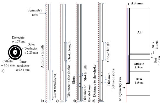
Figure 1.
Axi-symmetric geometry of the micro-coaxial antennas. (a) micro—coaxial cable transversal view and its diameters. (b) Metal—tip monopole (MTM) antenna, (c) Choked metal—tip monopole (CMTM) antenna, (d) Double slot (DS) antenna and (e) choked double slot (CDS) antenna, (f) Antenna inserted in a multilayer tissue model to evaluate its performance.
2.1.2. Double Slot (DS) and Choked Double Slot (CDS) Antennas
These are the most common type of microwave antennas, especially because of the easiness of their construction. In this case, the inner and the outer conductor (See Figure 1a) are soldered at the distal tip of the antenna. A small slot (less than one-tenth) of the effective wavelength is cut around the outer conductor near the solder point to allow propagation of the electromagnetic wave in the tissues [45]. The slots must be located near to the short-circuit at the distal tip to allow the wave propagation through the tissue. The slots are air grooves that allow a major concentration of heat near their location, i.e., they work as a guide to the electromagnetic radiation. The choke has the same goal as previously described. Figure 1d,e shows the geometrical design of both antennas.
2.2. Finite Element Model
The symmetry that exists around an axis when all the semi-planes exhibit the same characteristics allow us to work with axisymmetric geometries. The lower computational cost required to solve problems by using axisymmetric geometries compared to that required to solve 3D problems is one of the main advantages; therefore, an axisymmetric geometry was proposed to perform this study. In the axial-symmetric mode, there is no change in the azimuthal direction i.e., the φ direction.
Therefore, these waves have a magnetic field only with a φ component and an electric field in the r–z plane. The fields can be written as described in Equations (3) and (4):
In order to evaluate the antennas performance, models based in the finite element method were developed. The models were generated by considering that the electromagnetic wave propagated through the coaxial cable is defined by transversal electromagnetic fields (TEM). Time—harmonic fields were considered, then the wave propagation can be described by Equations (5)–(7):
where z is the direction of propagation, and r, φ, and z are the cylindrical coordinates of the coaxial cable. Pav is the averaged power flow, R is the cable impedance; while router and rinner are the radius for outer and inner conductor, respectively, ω is the angular frequency and k is the propagation constant, which is linked to the wavelength at the medium (λ), as described by Equation (8):
In tissue, the electric field has a finite axial component since the magnetic field is completely in the azimuthal direction. The wave equation then becomes scalar , as it is shown in Equation (9):
where and are the relative permittivity and permeability, respectively. The boundary conditions for the metallic surfaces are described by Equation (10):
The feed point was modeled as a port boundary condition with an input power level set to 5 W. In this problem, a low reflecting boundary condition was set on the surfaces; therefore, the boundary does not disturb the electromagnetic field distribution. The input field is described by Equation (11):
where
for an input power of deduced from the time-average power flow. The antenna radiates into the tissue where a damped wave propagates. Due to a finite region that was discretized, the geometry must be truncated at some distance from the antenna by using a similar absorbing boundary condition without excitation. The boundary conditions can be applied to all exterior boundaries. A symmetry boundary condition for boundaries at r = 0 were applied.
Electromagnetic and thermal simulations were solved by the finite element method by using COMSOL-Multiphysics (COMSOL Inc., Burlington, MA, USA). The electromagnetic (EM) simulations were carried out in the frequency domain (2.45 GHz), while the thermal simulations were calculated in the time dependent domain. In order to reduce the computation time and due to the antenna symmetry, 2D axisymmetric models were implemented (See Figure 1f). In these models, cortical bone was not considered because the bone tumors usually grow up around the cancellous bone.
To determine the directional properties and to detect the side lobs of the designed antennas; directivity calculations were performed by using COMSOL-Multiphysics. These calculations allow to know the ratio between the radiation intensity in a given direction of the antenna and the radiation intensity averaged in all directions. The directivity measurement allows us to define the heating pattern generated during heat treatment in bone cancer. For this study, the E plane of the antennas was obtained, since the greatest contribution to tissue thermal damage is due to the electric field in the bone.
2.2.1. Microwave Propagation in Tissue
The absorption and propagation of the microwaves in the tissue are governed by Maxwell’s equations. The electromagnetic fields radiated in tissue by an antenna can be estimated by solving the Maxwell’s equations; however, tissue electromagnetic properties (permittivity and conductivity) and initial and boundary conditions must be known [37]. Therefore, it is extremely important to know the dielectric tissue properties and how they change during the ablation procedure, to develop accurate models and predict the antenna performance.
2.2.2. Electromagnetic Models
The EM simulations were used to calculate the specific absorption rate (SAR), which represents the electromagnetic field deposited by unit of mass in the tissue (W/kg). Equation (13) defines the SAR generated by each antenna [46]:
where σ (S/m) is the conductivity, ρ (kg/m3) is the tissue density, and E is the electric field generated by each antenna. The slots were defined as air, the antenna boundaries (all the antennas), as well as the choke as perfect electric conductors, while the excitation boundaries were defined as a coaxial port, fed by 5 W and 10 W of input power. The tissue boundaries were set as a scattering boundary condition to ensure that the EM wave will pass without reflections.
2.2.3. Thermal Models
To implement the thermal models, the Bioheat equation (Equation (14)) was used [46]. This equation models the heat transfer in tissue, as well as the impact of perfusion as an isotropic heat sink. Bioheat equation is described as:
where c (J/kg/K) represents the heat capacity, ρ (Kg/m3) density, k (W/m/K) thermal conductivity, ρb (kg/m3) blood density, Cb (J/kg/K) heat capacity of blood, W (kg/m3/s) blood perfusion, Tb (K) blood temperature, Q (W/m3) rate of heat generated by metabolism and SAR (W/kg) the specific absorption rate. The SAR previously calculated by the electromagnetic models was used as a source for the thermal simulations. In all the models, the blood perfusion and the heat generated by metabolism were neglected. A time dependent study was implemented to evaluate the thermal distribution after 5 min of application. The initial tissue temperature was set at 37 °C. Table 1 shows the dielectric and thermal properties of each tissue and the materials that were considered in the models.

Table 1.
Dielectric and thermal properties, for the tissues and antennas, used in the modeling.
2.2.4. Antenna Optimization: Parametric Study
In order to optimize each one of the proposed antennas, a parametric study was implemented. Table 2 describes the parameters included in this study, as well as their values. It is important to address that for each antenna different parameters were analyzed.
Table 2.
Parameters used for the implementation of the parametric study to optimize each antenna.
2.2.5. Convergence Analysis
The goal of mesh adaptation is to use as few elements as possible to obtain an accurate solution. In general, it is desirable to use a coarser mesh in the regions that are not very important and a more refined mesh in the regions of interest. To adapt a mesh, it is necessary to provide the desired element size; finding the correct size of the elements is not an easy task. For these models, finite element mesh refinements were generated in order to carry out a convergence study. The parameters evaluated were the simulation time and the SWR values versus number of elements. A finer mesh size can require a significant computational cost, in addition the results can be overestimated. On the other hand, a coarser mesh size will cause the underestimation of the results. The values of the tested element size were , , , (submultiples of λeff).
2.3. Antenna Construction
Based on the results from the optimization, the antennas with the best characteristics (SWR, temperature, etc.) were constructed. Semirigid micro-coaxial cable UT-085, Amphenol RF connectors, a 6 mm copper bar, tin-lead solder, and a homemade lathe with 0.01 mm of resolution were the materials and equipment used to construct the antennas [5,22,23,24,29].
2.4. Phantoms Development
In order to evaluate the performance of the micro-coaxial antennas, several tissue emulators (phantoms) were developed. A phantom is a mixture of different components proposed in order to emulate the tissue properties [42]. For MWA applications, it is necessary to reach relative permittivity and electrical conductivity like those from the emulated tissue. The proposed phantoms are an ideal representation of human tissues, i.e., they are considered as homogenous. A multilayer phantom with fat, muscle, cortical and cancellous bone was developed. In this case, the skin layer was not considered due to the energy focalization, i.e., the skin is not affected by the heat generation. Table 3 describes the dielectric tissue properties at 2.45 GHz used to develop each phantom.
Phantom Characterization
In order to emulate the dielectric tissue properties, each phantom tissue sample was characterized. The experimental set-up consisted in the HP 85070C Dielectric Probe Kit (Hewlett Packard, Palo Alto, CA, USA) connected to a network analyzer (E5071B ENA, Agilent Technologies, Santa Clara, CA, USA). A GPI to USB converter (82357A, Agilent Technologies, Santa Clara, CA, USA) was used to connect it to a personal computer where the software Agilent Connection and Dielectric software (Agilent Technologies, Santa Clara, CA, USA) were installed. The dielectric probe is based on the open-ended coaxial line. The dielectric phantom tissue properties were determined by the measurement of the reflection coefficient at the probe interface. The phantom tissue characterization was done from 2 GHz to 3 GHz. It is important to address that the phantom is assumed to be non-magnetic, isotropic, and homogeneous. The permittivity of each phantom tissue was measured by placing the dielectric probe over and inside the sample. Several measurements were done in order to evaluate the homogeneity of the samples; mean values and standard deviations were calculated. The Dielectric Probe Kit measures in a direct way the permittivity (ε) of the sample; however, the electrical conductivity (σ) was calculated by using the dielectric loss factor (ε”) which is also provided by the Dielectric Probe Kit. Equation (15) was used to calculate the electrical conductivity by using the dielectric loss factor [47].
where σ is the electrical conductivity, ε″ is the dielectric loss factor, ε0 is the permittivity of free space, and ω = 2πf is the angular frequency (rad/s). Finally, once the phantoms that emulate the tissue properties were ready, a multilayer phantom was done. These multilayer phantoms emulated fat, muscle, and bone tissue. The layer of fat had a thickness of 1 cm, 1.5 cm for the muscle, and 3 cm of bone tissue (cortical and cancellous) phantom. The 3 cm of bone tissue phantom thickness was proposed to be able to insert the antenna over it.
Table 3.
Dielectric tissue properties at 2.45 GHz to be emulated in the tissue phantoms [48].
Table 3.
Dielectric tissue properties at 2.45 GHz to be emulated in the tissue phantoms [48].
| Tissue | Relative Permittivity (—) | Electrical Conductivity (S/m) |
|---|---|---|
| Cortical bone | 11.4 | 0.39 |
| Spongy bone | 18.5 | 0.80 |
| Muscle | 52.7 | 1.74 |
| Fat | 10.8 | 0.26 |
2.5. Antenna Characterization
2.5.1. Standing Wave Ratio (SWR)
The SWR measure the impedance coupling between a load and the transmission line that supplies it. The ideal SWR value is 1, this means that all the input power has been transmitted to the tissue. A higher SWR value (greater than 1) indicates a greater power loss in the antenna and, therefore, greater power backs to the microwave system. In this case, the SWR was measured for both cases, i.e., when the antenna was inserted either in the multilayer phantom or in the ex vivo porcine tissue at different insertion depths.
To carry out the SWR measurements, the Agilent Technologies E5071B network analyzer was used at the work frequency of the antennas (2.45 GHz). Figure 2a depicts the experimental setup. Some previous studies showed that the insertion depth of the antennas plays an important role in the SWR values [18]. Therefore, the antennas performance when they were inserted at different depths in the multilayer phantom, as well as in the ex vivo tissue, was evaluated.
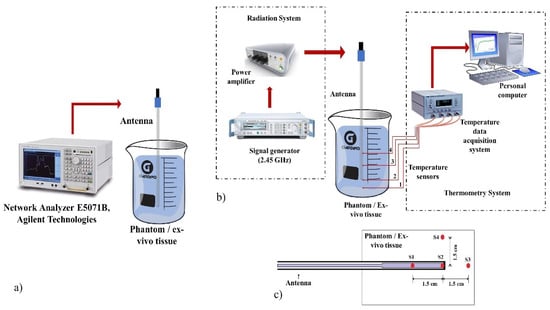
Figure 2.
Experimental set-up to evaluate the antenna performance. (a) Experimental setup to measure the SWR of the antennas inserted in the multilayer phantom and the ex vivo porcine tissue, (b) Radiation and thermometry system used in the experimental tests, (c) Temperature sensors location (S1, S2, S3, and S4) to measure the temperature generated for the antennas.
2.5.2. Radiation System Used in the Experimentation
The radiation system consists of an SSPA Aethercomm power amplifier and a Rohde & Schwarz SML03 microwave generator to which the antenna was connected; the microwave generator works at a frequency of 2.45 GHz. Figure 2b shows the radiation system used to implement all the experiments.
2.5.3. Thermometry System Used in the Experimentation
The thermometry system was based on optical fibers Luxtron MAR05 STB that allows to measure the temperature during the experimentation. Optic fiber thermal probes do not interfere with microwave radiation [49]. Therefore, the thermometry system was integrated by non-interfering fiber optic thermal probes to measure temperature at real time during the MW experiments. Figure 2b shows the configuration of the thermometry system for the experimental tests. Four sensors were located on the antenna body and inside of the tested material (either a multilayer phantom or ex vivo tissue). The sensors were located at the antenna tip (S2), where the temperature was higher, 1.5 cm up (S1) and down (S3) to the antenna tip, and 1.5 cm (S4) next to the sensor S2 as can be observed in Figure 2c. The sensor location was determined by preliminary experiments where thermal distributions of the antennas were obtained. Sensors were located at places where the recorded temperatures were above 60 °C. In order to compare the antennas performance, the sensors were located at the same places.
2.5.4. Experimentation in Multilayer Phantom
To evaluate the efficiency of the four antennas, different experimental tests were implemented in multilayer phantoms. The experiments were done by applying an input power of 5 W and 10 W per 5 min. In order to emulate the physiological temperature, the multilayer phantoms were heated up to 37 °C by using a thermal bath. Once the 37 °C were reached in the phantoms, the antenna and the sensors were placed inside it. The antennas were covered with a Teflon™ layer; this layer allows the tissue or phantom, which are in direct contact with the antenna, not to be adhered to the antenna body. Figure 3a,b show the experimental test with a phantom inside the thermal bath as well as the antenna, with the Teflon™ layer, connected to the radiation system.
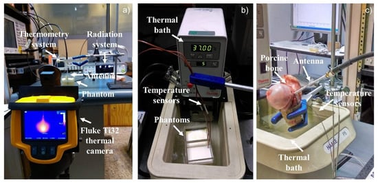
Figure 3.
Experimental set-up used to record the temperature increase in the multilayer phantoms and the ex vivo porcine tissue. (a) Experimental set-up used to take the thermal distributions by the thermal camera, (b) Experimental set-up to perform the experimentation in a multilayer tissue phantom, (c) Experimental Set-up to perform the experimentation in ex vivo tissue.
2.5.5. Experimentation in Ex Vivo Porcine Tissue
The experimentation in ex vivo porcine tissue (porcine femur bone) was done with the antennas that showed the best performance during the multilayer phantom experimentation. The radiation and the thermometry system were the same, as well as the temperature sensors location. In order to insert the antenna and the temperature sensors, the bone was cut in a half, once both were inserted, the bone was rejoined, as can be observed in Figure 3c.
The bone was heated up to 37C in a thermal bath. Just a small section of the bone was submerged in the thermal bath, in order to prevent the antenna from getting wet. The thermal bath temperature was set at 55 °C and the bone was heated for 15 min to reach 37 °C. Once the bone reached the target temperature, the radiation tests were performed. Figure 3c shows the performance of the experimental tests in ex vivo tissue.
2.5.6. Thermal Distributions
The thermal distributions generated by the antenna were obtained with a Fluke Ti32 thermal camera. Due to the thermal camera being able to take only superficial thermal images, the thermal distributions were taken through the surface of the acrylic containers of each phantom, as can be observed in Figure 3a. Due to the presence of the acrylic, the temperatures do not correspond to the ones reached in the phantoms; therefore, these photographs were taken just in order to know the thermal distribution shape generated by each antenna. In order to evaluate the evolution of the thermal distribution, five photographs were taken to observe the damage in the multilayer phantoms every minute. The first one was obtained after one minute of radiation, and every minute a new one was taken. For the ex vivo porcine bone, at the end of the experiment, the bone was separated, and a photograph of the bone surface (the one that was in contact with the antenna) was taken.
2.5.7. Comparison between Antennas
The standing wave ratio (SWR), maximum temperatures, power loss, thermal distribution and insertion depth are the most important parameters to predict the efficiency of microwave antennas designed to treat tumors by thermal ablation. These parameters were evaluated and compared in order to analyze the performance of each one of the proposed antennas.
3. Results
3.1. Convergence Analysis
The convergence analysis was done in order to choose the mesh size that allows to obtain a precise solution in a reasonable computational time.
In the convergence analysis, the relation between SWR and simulation time versus number of mesh elements was obtained. It was observed that the lowest number of mesh elements (2000–4000) (faster simulations), underestimates the results. However, for a mesh with around 4000–6000 elements, the SWR was around 1.5 and the simulation time was stable in approximately 15–18 s. Choosing the appropriate mesh size for the simulations will help to obtain a closer estimation of the antenna performance in real life. In this case, the best mesh was the one defined by λeff/10, where the SWR was around 1.5 and the simulation time was 16 s. As a result, all the implemented simulations were carried out with a mesh size defined by λeff/10.
3.2. Antenna Design
The parametric study was carried out in order to obtain the optimal antenna design, i.e., the antenna dimensions that allows the maximum power transmission. The SWR was obtained in order to choose the best-case scenarios. As it is well-known, an SWR equal to 1 represents a total power transmission, while a higher value represents power losses and a mismatch between the MW system and the antenna. Table 4 shows the dimensions of each optimized antenna as well as their SWR values. Moreover, the Choked Double Slot (CDS) antenna had the lowest SWR (1.13), while the Metal-Tip Monopole (MTM) antenna had the highest one (1.55). However, the SWR for the four antennas was around 1.13—1.55 which means a good energy transmission. The optimization process showed that the worst-case scenarios reached SWR values around 2.40–6.35.
Table 4.
Geometry dimension for each optimized antenna.
The directivity plots (E-plane) obtained from COMSOL-Multiphysics are shown in Figure 4, for the four designed antennas. Each of these plots allows us to evaluate the characteristics of the radiation pattern of each of the antennas and thus to know the tissue damage during treatment. All the antennas present two main lobes and two secondary lobes in the directivity pattern. Figure 4a shows the directivity of the Double Slot (DS) antenna, it has a beamwidth of the main lobes of more than 90° with a gain of about 10 dB. Figure 4b shows the directivity of the Choked Double Slot (CDS) Antenna, its antenna has a main lobe beamwidth of 15° with a gain of about 15 dB. Figure 4c shows Metal-tip Monopole (MTM) Antenna directivity, this antenna has a beamwidth of 45° and a gain of 21 dB, and finally, Figure 4d, the Choked Metal-tip Monopole (CMTM) Antenna, which has a beamwidth of 15° and a gain of 15 dB.
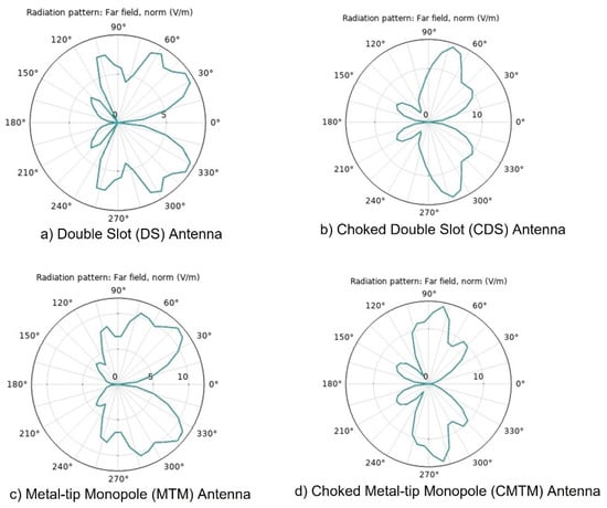
Figure 4.
Directivity diagrams for the designed antennas. (a) Double Slot antenna, (b) Chocked Double Slot antenna, (c) Metal-Tip Monopole antenna, (d) Chocked Double Slot antenna, obtained by using COMSOL-Multiphysics.
3.3. Antenna Construction
Due to the fact that the radiation pattern of the antennas changes according to the environment in which it is immersed, e.g., phantom or ex vivo tissue, the antenna was designed, by modeling, to irradiate bone, muscle, and skin tissue. On the other hand, the experimentation was carried out in different stages to evaluate the effect of the antennas to irradiate different media (phantoms and ex vivo bone tissue). Figure 5 shows the four antennas that were constructed by following the results shown in Table 4, as well as the antennas tested in porcine ex vivo tissue. The antennas were covered with TeflonTM for the experiments on phantoms as well as on ex vivo tissue as shown in Figure 5e,f.
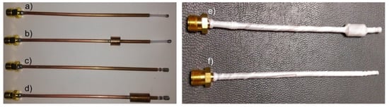
Figure 5.
Micro-coaxial antennas. (a) Metal-Tip Monopole antenna, (b) Chocked Metal-Tip Monopole antenna, (c) Double Slot antenna, (d) Chocked Double Slot antenna, (e) Chocked Double Slot antenna tested in porcine ex vivo tissue and (f) Metal-Tip Monopole antenna tested in porcine ex vivo tissue.
3.4. Phantoms Characterization
Table 5 shows the materials as well as the concentrations used to emulate relative permittivity (εr) and electrical conductivity (σ) of cortical and cancellous bone, muscle, and fat tissues. By using the materials and concentrations reported in the Table 5, the tissue phantoms were prepared. In order to characterize each phantom, the relative permittivity was measured in a direct way; while the electrical conductivity was calculated by using the dielectric loss factor. It is important to address that neither in the simulations nor in the experiments thermal dependence of tissue properties were considered and just the constant values reported in literature were emulated. Table 6 shows the mean value and standard deviation obtained from the measures of each tissue property.
Table 5.
Materials and concentrations used to develop the multi-layer phantom tissue.
Table 6.
Dielectric properties measured in the characterization of the tissue phantoms.
3.5. Antenna Comparison: Experimentation in Multilayer Phantom
3.5.1. Standing Wave Ratio (SWR) and Insertion Depth in Multilayer Phantoms
The antennas performance was evaluated when they were inserted at different depths in the multilayer phantom. The analyzed depths were 0 mm of insertion, which means that the antenna was only in contact with the surface of the cortical bone phantom layer, 4 mm, 8 mm, 12 mm, 16 mm, and 20 mm within the layer of bone phantom, as in the computational models. The antenna that shows better SWR values and therefore better power delivery was the DS antenna. The CMTM antenna had SWR values greater than 2 at most of the insertion depths, so this antenna will tend to generate larger power loss and less energy delivery. The DS antennas showed better performance at a deeper insertion distance, so this antenna design holds promise for treating bone tumors located deeper in bone tissue. The MTM antenna showed a better SWR (1.7) at an insertion depth of 12 mm; the CMTM antenna at 8 mm (SWR = 2.5), the DS antenna at 16 mm (SWR = 1.3), and the antenna CDS at 20 mm (SWR = 1.6). At these insertion depths, the lowest SWR value was obtained for each antenna, which indicates that a better coupling with the tissue will be obtained. Therefore, all the next antenna evaluations were tested at these insertion depths.
3.5.2. Power Loss
The reflected power allows to know the percentage of power that is being returned to the radiation system. A high percentage of reflected power not only implies a greater loss of energy, but also indicates the inefficiency of the antennas to transmit the energy to the tissue to be treated; moreover, a higher reflected power can damage the radiation system. The power amplifier used in the experiments can record the input power as well as the reflected one; in this way, the amount of power loss was obtained. For the tests carried out with 5 W, the power loss was not greater than 1 W for any antenna; while in experiments with 10 W, the maximum power loss was 1.2 W. This indicates that the antennas delivered more than 85% of the power to the multilayer phantom. The antenna with the lowest power loss was the CDS with 6.4% of reflected power (input power= 5 W) and the MTM with 7.4% of reflected power (input power = 10 W). The MTM and CDS antennas showed the best performance.
3.5.3. Temperature Profiles
Figure 6 shows the temperature profiles obtained by the four temperature sensors when the antennas were fed with 5 W and 10 W. The highest temperatures were obtained at S2, these temperatures were higher than 65 °C when using 5 W and higher than 80 °C when using 10 W; therefore, the highest energy deposition was at the tip of the antennas. The second highest reached temperatures, between 60–65 °C when using 5 W and between 77–82 °C when using 10 W, were recorded at S1, which was located at 1.5 cm above the antenna tip. The MTM antenna exceeds 70 °C, 20 s and 5 s earlier than the CMTM by using 10 W and 5 W, respectively. This implies that the use of the choke on the CMTM antenna not only focuses the energy below the choke, but also causes the temperature rise to be more linear and controlled compared to the MTM antenna. However, for the DS antenna, the temperature rise tends to be like the CDS antenna, which means that the choke only has this effect over the temperature profiles generated by the MTM antenna. Figure 6a shows that the MTM antennas reached ablation temperatures before 100 s of radiation, while the DS antennas (Figure 6c) reached ablation temperatures after 100 s (input power = 5 W). However, S3 and S4 did not reach temperatures above 60 °C, which indicates that at 1.5 cm below and next to the antenna tip, the ablation temperatures were not achieved. The maximum temperature was achieved by the MTM antenna with 83 °C, while the CDS antenna reached a maximum temperature of 68 °C in the experiments with 5 W. There was a ΔT= 15 °C between the antenna with the highest temperature (MTM) and the one with the lowest temperature (CDS).
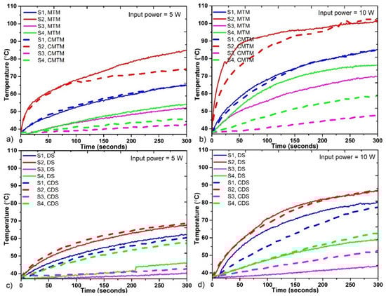
Figure 6.
Temperature profiles reached by each antenna during the experiments. (a) Comparison between the MTM and the CMTM antennas fed with 5 W, (b) Comparison between the MTM and the CMTM antennas fed with 10 W, (c) Comparison between the DS and the CDS antennas fed with 5 W, (d) Comparison between the DS and the CDS antennas fed with 10 W.
For experiments with 10 W of input power, MTM antennas (Figure 6b) show a higher temperature increase compared to DS antennas as shown in Figure 5d. In this case, temperatures above 60 °C in S2 were reached almost twice faster than in the cases with 5 W. The MTM antennas reached ablation temperatures before 50 s, while DS antennas reached ablation temperatures before 100 s. This proves that the use of higher power implies the generation of high temperatures in a shorter time. By using 10 W, only the S4 in the four antennas does not reach ablation temperatures. Moreover, in all cases, it was possible to observe the effect of the choke over the heat regulation in the tissue.
3.5.4. Experimental Thermal Distributions
Figure 7 shows the experimental thermal distributions generated by each antenna with an input power of 5 W applied per 5 min. The thermal distributions show the areas of the phantom where the heat was focused. In this case, the use of 5 W or 10 W of input power just modifies the size of the thermal distribution, but the shape was the same. Therefore, only the experimental thermal distributions generated by using 5 W are presented. Even though the increase in temperature was generated quickly at the tip of the antennas when the experiment was started, the thermal distribution begins to be visible after 2 min of MW exposure. These thermal distributions depend on the radiation time; the longer the radiation time, the larger the thermal distribution.
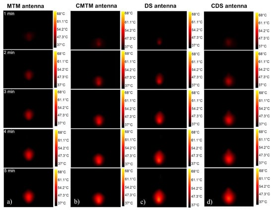
Figure 7.
Experimental thermal distributions generated by each antenna through 5 min of radiation (a) Thermal distributions generated by the MTM antenna., (b) Thermal distributions generated by the CMTM antenna, (c) Thermal distributions generated by the DS antenna, (d) Thermal distributions generated by the CDS antenna through the 5 min.
The thermal distributions generated by the MTM antennas were focused on the antenna tip (Figure 7a,b); while the thermal distributions generated by the DS antennas start to be spread around the slots (Figure 7c,d), which causes a thermal distribution longer than the one generated by the MTM antennas. The energy focusing on the antenna tip was due to the greatest microwave propagation occurring at the antenna body where the outer conductor was removed to create the monopole and the antenna slots. For the DS antennas, the outer conductor of the antenna was removed to create the slots, whereas in the MTM antennas, the outer conductor was removed to create the monopole.
As can be observed in Figure 7d, the CDS antenna generates an energy focus under the choke, this causes a thermal distribution shape like a drop of water; while with the DS antenna (Figure 7c), the thermal distribution shape was spherical. This indicates that the choke in the CDS antenna reduces the backward heating along the shaft during the ablation procedures. The choke in the CMTM antenna had less impact on the thermal distribution because its position was not so close to the antenna tip as in the CDS antenna. Therefore, the distance between the antenna tip and the choke can modify the thermal distribution, i.e., the closer the choke to the antenna tip, the greater the focus of energy at the antenna tip. On the other hand, the farther the choke is from the tip of the antenna, the focusing will be reduced.
3.6. Experimentation in Ex Vivo Bone Tissue
Experimental results in the multilayer phantoms showed that the MTM and the CDS antennas had a better performance than the CMTM and DS antennas. For that reason, the MTM and the CDS antennas were chosen as candidates to perform the experimental tests in ex vivo tissue. Because this evaluation was carried out in ex vivo tissue, new insertion depths in function of the bone size were analyzed.
3.6.1. Standing Wave Ratio (SWR) and Insertion Depth
The insertion depths of the antennas were 8 mm, 12 mm, 16 mm, and 20 mm for the MTM antenna and 5 mm, 15 mm, 25 mm, and 35 mm for the CDS antenna. In order to evaluate if the whole insertion of the choke in the bone influences the SWR, the evaluated depths for the CDS antenna were greater than the ones used for the MTM antenna. Table 7 shows the SWR measured for each antenna. The antennas were optimized to work in a multilayer tissue. However, in this case, they were evaluated in bone tissue; therefore, the SWR tended to be higher. For cases in which the inner conductor of the MTM antenna was inserted at depths either equal or lower than 12 mm, the SWR was greater than 2. However, when the inner conductor was inserted at depths between 16 mm and 20 mm, the SWR was lower than 1.5. This means that if the entire length of the inner conductor of the MTM antenna is inserted to the bone tissue, the energy transmission is better. On the other hand, the cases where the CDS antenna was inserted at depths either equal or lower than 15 mm, the SWR was greater than 2. At these depths, the choke was not entirely within the bone. For insertion depths of 25 mm and 35 mm (with the complete choke inside the bone) the SWR was lower than 1.5. The best-case scenario for the MTM antenna was at 16 mm of insertion depth, while the best one for the CDS antenna was at 35 mm. These insertion depths were selected to perform the experiments to get temperature profiles, power losses, and thermal distributions.
Table 7.
Measured SWR values for different insertion depth in porcine ex vivo tissue.
3.6.2. Power Loss
The maximum percentage of reflected power presented by the MTM antenna, with an input power of 5 W and 10 W, were 16% and 12.5%, respectively; while the CDS antenna showed a maximum percentage of reflected power of 6.4% and 5.2%, for an input power of 5 W and 10 W, respectively. The CDS antenna had the lowest SWR, and the lowest power loss as shown in Table 8. The reflected power for the MTM antenna was two times higher than the one for the CDS antenna. However, in all the cases the delivered power to the bone was greater than 80%.
Table 8.
Comparison between computational models, multilayer phantom and ex vivo experiments for MTM and CDS antennas using 5 W per 5 min.
Table 8 shows the comparison between the results of both antennas in the FEM model and experimentation in phantoms and ex vivo tissue. The SWR values were different in each experiment, for example, both antennas show a lower SWR value in ex vivo experiments; while in the experiments in multilayer phantoms, it is observed that the SWR values were greater even than those obtained in the FEM models. These differences may be because in both (computational models and phantom experiments), the thermal dependence of the dielectric tissue properties was not considered. Moreover, the antenna insertion was different for the experimentation in ex vivo tissue. However, in all the cases, the SWR values were lower than 1.8 and the power loss values lower than 17% in the experiments in phantoms and ex vivo tissue, showing a good performance for both antennas.
3.6.3. Ex Vivo Bone Thermal Distributions
Figure 8 shows the thermal distributions generated by the antennas with an input power of 5 W and 10 W after 5 min of radiation. The thermal distribution generated by the MTM antenna had the same spherical shape in both cases (5 W and 10 W); therefore, the difference was observed in the reached temperatures. The CDS antenna had an elongated thermal distribution. In the thermal distribution generated by the CDS antenna with 5 W, it was observed that the thermal distribution is more concentrated just next to the start of the choke, resulting in less damage to healthy tissue. The thermal distribution generated by the MTM antenna was similar to a semicircle; in this case, it was not like a complete circle as the one obtained in phantom experimentation (See Figure 7a). This was because in the phantom experiments the monopole was entirely inside the tissue; while, in the ex vivo tissue experiments, the monopole was not totally inside the bone, so the thermal distribution was affected by the insertion depth of the antenna. On the other hand, in the CDS antenna, a complete thermal distribution is observed because both the choke and the slots were inside the bone tissue.
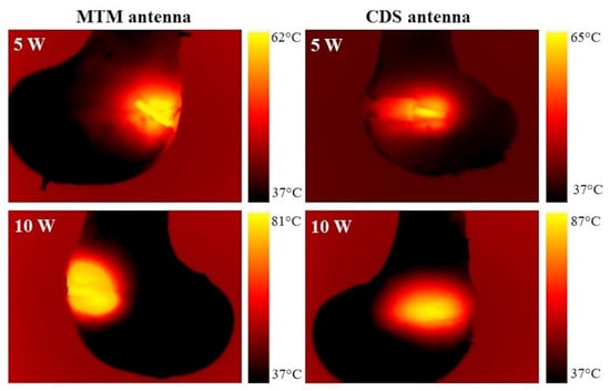
Figure 8.
Thermal distribution generated by an MTM and CDS antenna in porcine ex vivo tissue.
3.6.4. Ex Vivo Bone Temperature Profiles
Figure 9 shows the temperature profiles measured in the porcine ex vivo experimentation. The MTM antenna (Figure 9a) shows a temperature increase in less time; for an input power of 5 W, it exceeds 60 °C before 100 s of radiation, while the CDS antenna exceeds that temperature after 200 s of radiation. For both antennas, only the S2 sensor at the antenna tip exceeds 60 °C when 5 W were used.
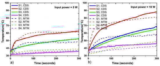
Figure 9.
Temperatures reached by each antenna during the experiments in porcine ex vivo tissue. (a) Temperature profiles reached with 5 W, (b) Temperature profiles reached with 10 W.
The temperature profiles generated by the MTM antenna after 100 s of radiation showed a constant temperature increase; while the ones generated by the CDS antenna increase during all the experiments. The experiments with 10 W (Figure 9b) showed that both antennas exceed 80 °C in sensor S2. For the CDS antenna, in sensors S1, S2, and S3, temperatures above 60 °C were reached after 200 s of radiation. The CDS antenna generates the highest temperature (87 °C) of both antennas. The temperature difference between the MTM and CDS antenna at the antenna tip was 6 °C. In addition, the sensor S3, which was located under the antenna tip, reached a higher temperature for the CDS antenna than for the MTM antenna. The temperature difference at sensor S3 was approximately 10 °C and 18 °C for 5 W and 10 W of input power, respectively. In this case, the choke in the CDS antenna generates a greater energy deposition under the choke, thereby generating a greater increase in temperature.
4. Discussion and Conclusions
This paper shows the design of four types of new micro-coaxial antennas specifically designed for thermal ablation in bone tissue in order to treat bone tumors. The proposed antennas were a metal-tip monopole (MTM), a choked metal-tip monopole (CMTM), a double slot (DS), and a choked double slot (CDS).
- The antennas were modeled (optimized) and experimentally evaluated by using multilayer phantoms and ex vivo porcine bone, i.e., the best modeled antennas were manufactured and tested. The computational models, despite finding differences with the experimental results, can be considered a good representation of the proposed antennas, i.e., for the MTM antenna, the SWR values were 1.55 and 1.24, while for the CDS antenna the SWR values were 1.13 and 1.12 for FEM model and ex vivo experimentation, respectively. Although in these cases (FEM model and ex vivo experimentation) the penetration depth of the antenna was not the same, due to the characteristics of the porcine bone, the SWR was not drastically modified. This performance could be an indicator of the effectiveness of the antenna optimization of the antennas. However, it is necessary to implement modifications in the FEM models such as the thermal dependence of dielectric and thermal properties of the tissues as well as the thermal dependence of perfusion, in order to obtain a better correlation between the models and the experiments.
- The study of the insertion depth in the antennas shows that the SWR value changes at different depths, for example, the DS and CDS antennas show a lower SWR value at higher insertion depths; while the MTM and CMTM antennas have a lower SWR value if the insertion depth is lower than 16 mm. In the experimentation when using multilayer phantoms, it was observed that if the slots, the monopole, and the choke of the antennas are completely inside the bone layer, the SWR values tend to be lower compared to the values obtained when they are not completely inside the bone tissue. Moreover, the choke modifies the thermal distribution, the CMTM and CDS antennas show a major energy focalization below the choke. Temperatures higher than 60 °C were reached in the multilayer phantom experiments with the four proposed antennas using 5 W as input power per 5 min. The best cases were obtained with the MTM and CDS antennas. The SWR values for both antennas were lower than 1.5; while the power loss was lower than 8%. The maximum temperatures, with 5 W as input power, obtained in the multilayer phantom experiments, were 83 °C for the MTM antenna and 68 °C for the CDS antenna; while in the ex vivo experiments, the maximum temperature was 62 °C for MTM antenna and 64 °C for CDS antenna. However, the lesion size in the biological tissue can be controlled by the input power and the treatment time, i.e., by increasing these parameters, the four designed antennas can increase the tissue damage size.
- In the experimentation in multilayer tissue phantoms, one of the most important points to be addressed is the development of the phantoms to emulate the tissue properties. It is important to emulate carefully the tissue properties because the dielectric properties of the tissues are highly dispersive and change according to the kind of tissue [50], water content [51], and temperature [52]. In this case, due to the difficult to emulate thermal properties, just dielectric properties were emulated; however, more research about how to correctly emulate thermal properties must be done.
- In the experiments in ex vivo tissue, temperatures higher than 60 °C were reached by using 10 W of input power per 5 min with both antennas. It was observed that with these optimized antennas a reduction in the input powers as well as in the treatment times was achieved. The literature reports input powers around 60 W for treatment times between 20–30 min [15,16]. In the ex vivo experiments, the CDS antenna had the best case with a SWR of 1.12 and a power loss of 6.8%; also, the temperatures measured by the S3 sensor, placed at 1.5 cm next to the antenna tip, reached temperatures higher than 60 °C ensuring that the damage caused to the tissue extends 3 cm in diameter.
- The difference of temperature between multilayer phantoms and ex vivo experiments were 21 °C for the MTM antenna and 4 °C for the CDS antenna. These differences between multilayer phantoms and ex vivo experiments may be because, in the ex vivo experiments, the tissue that was in contact with the antenna body goes from being healthy tissue to necrotic tissue in a short period of time (lower than 100 s of radiation). This can modify the dielectric properties of the tissue and consequently the SWR of the antennas change and a better coupling between the biological tissue and the antenna is obtained. Moreover, due to agarose being one of the multilayer tissue phantom components, it is also expected that the phantom starts its degradation when high temperatures are reached. This can also modify the coupling of the entire system.
- Finally, we can conclude that the proposed antennas for the treatment of bone tumors reached ablation temperatures as expected (>60 °C) by using 5 W and 10 W as input power per 5 min. These treatment times and input powers are lower than those reported in the literature [53].
- One of the main advantages of having four different antennas is that each one can be better adapted to the depth and shape of the tumor, for example, the DS antennas are candidates to treat deep tumors because they have a better coupling at greater insertion depths; while the MTM antennas have a better coupling (SWR = 1.24) with superficial tumors. On the other hand, the use of the MTM antenna in bone tissue presents better coupling compared to its use in soft tissue reported in the literature [19]. Moreover, it is important to address that this evaluation was done by considering just healthy bone tissue, because of the lack, in the literature, of the dielectric tissue properties for bone tumors.
- The future work includes the analysis of using antenna arrays to cover a larger area of bone tissue as well as in vivo experiments. Moreover, the most important challenge is to obtain the dielectric and thermal tumor properties to use them in future modelling studies to predict the real effect over different kinds of bone tumors.
- The directivity plots and antennas side lobes are related to the electric field distribution in the tissue to be treated, which, in turn, are related to the temperature distribution. The purpose of the minimally invasive treatment presented in this work is to generate temperatures above 60 °C to destroy the tumor tissue, without damaging healthy tissue; so in order to ensure the safety of the patients under treatment, as future work, these side lobes will be considered in the treatment planning, by using imaging methods (ultrasound or tomography), to know the volume of the tumor to be heated and to design the most appropriate treatment, considering the type and position (angle) of the antenna to be used to ensure localized damage in the tumor tissue, without damaging healthy tissue.
- Another important challenge is to generate thermal therapy in tumor tissue, to adjust the coupling of the antenna to the tissue, techniques such as modification of the antenna dimensions as well as capacitance changes can be used as a solution for accomplishing antennas alterations, as described in [54,55] respectively.
Author Contributions
Conceptualization, C.J.T.-R., L.L.-S. and A.V.-H.; Data curation, T.J.R.-G.; Formal analysis, T.J.R.-G. and C.J.T.-R.; Funding acquisition, L.L.-S.; Investigation, T.J.R.-G.; Methodology, T.J.R.-G., C.J.T.-R. and R.M.-V.; Resources, L.L.-S., A.V.-H. and J.G.-M.; Supervision, C.J.T.-R., L.L.-S., A.V.-H. and G.R.-M.; Validation, R.M.-V., G.R.-M. and J.G.-M.; Visualization, T.J.R.-G. and C.J.T.-R.; Writing—original draft, T.J.R.-G., C.J.T.-R., R.M.-V. and A.V.-H.; Writing—review & editing, C.J.T.-R., R.M.-V., A.V.-H., G.R.-M., R.O.-P. and J.G.-M. All authors have read and agreed to the published version of the manuscript.
Funding
We appreciate the funding for the development of the work to the projects: CYTED-DITECROD-218RT0545 and IV-8 call Amexcid-AUCI.
Acknowledgments
Authors thank J. H. Zepeda Peralta for his important technical assistance. Authors would like to thank the National Council for Science and Technology (CONACYT, Mexico) for the support received.
Conflicts of Interest
The authors declare no conflict of interest.
References
- Riccio, A. Metastatic Carcinoma of the Long Bones. Acad. Fam. Physicians 2007, 76, 1489–1494. [Google Scholar]
- American Cancer Society. Facts & Figures 2021; American Cancer Society: Atlanta, GA, USA, 2021. [Google Scholar]
- Erol, B.; Er, T.; Aycan, O.E.; Topkar, O.M. Bone Tumor: Types, Causes and Symptoms. Available online: https://www.healthline.com/health/bone-tumors#benign-tumors (accessed on 13 August 2021).
- Trujillo-Romero, C.J.; Rico-Martínez, G.; Gutierrez-Martinez, J. Thermal ablation: An alternative to bone cancer. Investig. En Discapac. 2018, 7, 35–46. [Google Scholar]
- Ramirez-Guzman, T.J.; Vera, A.; Leija, L.; Trujillo-Romero, C.J. Antennas Design for Microwave Ablation in Bone Tissue: Simulation and Experimental Validation. In Proceedings of the 2019 16th International Conference on Electrical Engineering, Computing Science and Automatic Control (CCE), Mexico City, Mexico, 11–13 September 2019; IEEE: Piscataway, NJ, USA, 2019; pp. 3–7. [Google Scholar] [CrossRef]
- West, T.B.; Alster, T.S. Percutaneous RF Interstitial Thermal Ablation in the Treatment of Hepatic Cancer. Am. J. Roentgenol. 1996, 167, 759–768. [Google Scholar] [CrossRef] [PubMed] [Green Version]
- Chiou, Y.Y.; Chou, Y.H. Radiofrequency ablation of hepatocellular carcinoma. J. Med. Ultrasound 2008, 16, 272–284. [Google Scholar] [CrossRef] [Green Version]
- Webster, J.G. Ablation. In Minimally Invasive Medical Technology; CRC Press: Boca Raton, FL, USA, 2001; pp. 219–225. [Google Scholar]
- Stuchly, M.A. Interaction of radiofrequency and microwave radiation with living systems. A review of mechanisms. Radiat. Environ. Biophys. 1979, 1, 1–14. [Google Scholar] [CrossRef] [PubMed]
- Schwan, H.P.; Foster, K.R. Microwave dielectric properties of tissue. Some comments on the rotational mobility of tissue water. Biophys. J. 1997, 17, 193–197. [Google Scholar] [CrossRef] [Green Version]
- Ryan, T.T.B.; Strohbehn, J.W. Physics of microwave hyperthermia. In Interstitial Hyperthermia: Physics, Biology and Clinical Aspects; CRC Press: Boca Raton, FL, USA, 1991; pp. 11–98. [Google Scholar]
- Niu, X. Microwave Ablation for Bone Tumors. Orthop. Muscular Syst. 2014, 3, 3–6. [Google Scholar] [CrossRef] [Green Version]
- Fan, Q.; Ma, B. Treatment of malignant or highly aggressive bone tumors of pelvis by microwaveinduced hyperthermia. Orthop. J. China 2009, 17, 961–964. [Google Scholar]
- Yu, Z.; Liang, X.; Huayang, H.; Tao, Z. The initial application of microwave ablation in situ in limb salvage surgery for soft tissue tumors with bone invasion. Chin. J. Clin. Basic Orthop. Res. 2011, 3, 263–266. [Google Scholar]
- Yang, X.; Zhang, Y.; Zhang, T.; Xu, L.; Ke, J.; Ma, L.; Lan, G.; Yao, Z.; Ouyang, L.; Huang, H.; et al. Prevention and control strategies of common post-operative complications of microwave ablation in situ in treatment of bone tumors. Chin. J. Reparative Reconstr. Surg. 2012, 26, 1473–1476. [Google Scholar]
- Gang, R.; Ya-min, S.; Xing, W.; Nan, L. Effect of repeated microwave hyperthermia inactivation on distal femur giant cell tumor. Acad. J. Chin. PLA Med. Sch. 2013, 34, 680–682. [Google Scholar]
- Ortega-Palacios, R.; Trujillo-Romer, C.J. Heat Transfer Study in Breast Tumor Phantom during Microwave Ablation: Modeling and Experimental Results for Three Different Antennas. Electronics 2020, 9, 535. [Google Scholar] [CrossRef] [Green Version]
- Lujan, F.; Pinilla, B.; Gutierrez-Martinez, J.; Vera-Hernandez, A.; Leija, L.; Trujillo-Romer, C.J. Theoretical model of MW antennas to treat bone tumors: One slot and one slot choked antennas. In Proceedings of the 2017 14th International Conference on Electrical Engineering, Computing Science and Automatic Control (CCE), Mexico City, Mexico, 20–22 September 2017; IEEE: Piscataway, NJ, USA, 2017. [Google Scholar] [CrossRef]
- Ibitoye, A.Z.; Orotoye, T.; Nwoye, E.O.; Aweda, M.A. Analysis of efficiency of different antennas for microwave ablation using simulation and experimental methods. Egypt. J. Basic Appl. Sci. 2018, 5, 24–30. [Google Scholar] [CrossRef]
- Cepeda, M.F.; Vera, A.; Leija, L. Coaxial antenna for microwave coagulation therapy in ex vivo swine breast tissue. In Proceedings of the 2010 7th International Conference on Electrical Engineering Computing Science and Automatic Control, Mexico City, Mexico, 5–7 September 2010; IEEE: Piscataway, NJ, USA, 2010; Volume 28, pp. 268–273. [Google Scholar] [CrossRef]
- Ortega-Palacios, R.; Vera, A.; Leija, L. Microwave Ablation Coaxial Antenna Computational Model Slot antenna comparison. In Proceedings of the 2012 Pan American Health Care Exchanges, Miami, FL, USA, 26–31 March 2012; Volume 29, pp. 58–61. [Google Scholar]
- Luna, J.F.L. Optimización de la Energia Entregada por un Aplicador de Doble Ranura Microaxial Para Tratamiento de Cancer de Mama Mediante Ablacion por Microondas Modelado FEM, Validacion en Phantom y Experimentacion In vitro e In vivo. Master’s Thesis, CINVESTAV, Mexico City, Mexico, 2015. [Google Scholar]
- Lara, J.E.; Vera, A.; Leij, L. Proposal for the application of microwave ablation as a treatment for breast cancer using interstitial applicators: Antenna design and FEM modeling. Glob. Med. Eng. Phys. Exch. Am. Heal. Care Exch. 2016, 31, 1–6. [Google Scholar]
- Manzanárez, A.; Lara, J.E.; Vera, A.; Leija, L. Influence of the surrounding tissues in the radiation pattern of microcoaxial antenna for the treatment of breast tumors. In Proceedings of the 2016 13th International Conference on Electrical Engineering, Computing Science and Automatic Control (CCE), Mexico City, Mexico, 26–30 September 2016; IEEE: Piscataway, NJ, USA, 2016; pp. 1–6. [Google Scholar] [CrossRef]
- Ortega-Palacios, R.; Trujillo-Romero, C.J.; Cepeda Rubio Vera, A.; Leija, L.; Reyes, J.L.; Ramírez-Estudillo, M.C.; Morales-Alvarez, F. Feasibility of Using a Novel 2.45GHz Double Short Distance Slot Coaxial Antenna for Minimally Invasive Cancer Breast Microwave Ablation Therapy: Computational Model, Phantom, and In Vivo Swine Experimentation. J. Healthc. Eng. 2018, 2018, 5806753. [Google Scholar] [CrossRef] [PubMed] [Green Version]
- Trujillo-Romero, C.J.; Rico-Martínez, G.; Leija-Salas, L.; Vera-Hernández, A.; Gutierrez-Martinez, J. Microwave ablation to treat bone tumors by using a double slot antenna: A modelling study. In Proceedings of the 2017 Global Medical Engineering Physics Exchanges/Pan American Health Care Exchanges (GMEPE/PAHCE), Tuxtla-Gutierrez, Mexico, 20–25 March 2017; IEEE: Piscataway, NJ, USA, 2017. [Google Scholar] [CrossRef]
- Martínez-Valdez, R.; Trujillo-Romero, C.J.; Castellanos, L.; Gutiérrez-Martínez, J.; Vera-Hernández, A.; Ramos, A.; Leija, L. Feasibility of the microwave and ultrasound ablation as alternatives to treat bone tumors. In Proceedings of the 2017 Global Medical Engineering Physics Exchanges/Pan American Health Care Exchanges (GMEPE/PAHCE), Tuxtla-Gutierrez, Mexico, 20–25 March 2017; IEEE: Piscataway, NJ, USA, 2017. [Google Scholar] [CrossRef]
- Ramírez-Guzmán, T.J.; Trujillo-Romero, C.J.; Vera-Hernández, A.; Leija, L. Micro-coaxial Monopole Antenna to Treat Bone Cancer: Design and Preliminary Experimentation. In Proceedings of the 2019 Global Medical Engineering Physics Exchanges/Pan American Health Care Exchanges (GMEPE/PAHCE), Buenos Aires, Argentina, 26–31 March 2019; IEEE: Piscataway, NJ, USA, 2019. [Google Scholar] [CrossRef]
- Trujillo, C.J.; Rico, G.; Leija, L.; Vera, A. Micro-Coaxial Slot Antenna to Treat Bone Tumors by Thermal Ablation: Theoretical and Experimental Evaluation. IEEE Lat. Am. Trans. 2018, 16, 2731–2737. [Google Scholar] [CrossRef]
- Trujillo-Romero, C.J.; Leija-Salas, L.; Vera-Hernández, A.; Rico-Martínez, G.; Gutierrez-Martinez, J. Double Slot Antenna for Microwave Thermal Ablation to Treat Bone Tumors: Modeling and Experimental Evaluation. Electronics 2021, 10, 761. [Google Scholar] [CrossRef]
- Ibitoye, Z.A.; Nwoye, E.O.; Aweda, M.A.; Oremosu, A.A.; Annunobi, C.C.; Akanmu, O.N. Optimization of dual slot antenna using floating metallic sleeve for microwave ablation. Med. Eng. Phys. 2015, 37, 91. [Google Scholar] [CrossRef]
- Brace, C.L. Dual-slot antennas for microwae tissue heating: Paraetric design analysis and experimental validation: Biophysics, technology and applications. Crit. Rev. Biomed. Eng. 2010, 38, 65–78. [Google Scholar] [CrossRef] [Green Version]
- Hand, J. Modelling the interacting of electromagnetic fields (10MHz-10GHz) with the human body: Methods and applications. Phys. Med. Biol. 2009, 53, 86. [Google Scholar]
- Luyen, H.; Hagness, S.C. A balum-free helical antenna for minimally invasive microwave ablation. IEEE Trans. Antennas Propag. 2015, 63, 959–965. [Google Scholar] [CrossRef]
- Huang, H.; Zhang, L.; Moser, M.A.; Zhang, W.; Zhang, B. A review of antenna designs for percutaneous microwave ablation. Phys. Med. 2021, 84, 254–264. [Google Scholar] [CrossRef] [PubMed]
- Fallahi, H. Antenna designs for microwave tissue ablation. Crit. Rev. Biomed. Eng. 2018, 46, 495–521. [Google Scholar] [CrossRef] [PubMed]
- Ryan, T.P. Comparison of six microwave antennas for hyperthermia treatment of cancer: SAR results for single antennas and arrays. Radiat. Oncol. Biol. 1991, 21, 403–413. [Google Scholar] [CrossRef]
- Bertram, J.M.; Yang, D.; Converse, M.C.; Webster, J.G.; Mahvi, D.M. Antenna design for microwave hepatic ablation using an axisymmetric electromagnetic model. Biomed. Eng. Online 2006, 5, 1–9. [Google Scholar] [CrossRef] [PubMed] [Green Version]
- Design Considerations for Antenna Applicators for Microwave Ablation. Available online: https://es.scribd.com/document/488197528/13-chapter-4-1 (accessed on 13 August 2021).
- Keangin, P.; Rattanadecho, P.; Wessapan, T. An analysis of heat transfer in liver tissue during microwave ablation using single and double slot antenna. Int. Commun. Heat Mass Transf. 2011, 38, 757–766. [Google Scholar] [CrossRef]
- Brace, C.L. Microwave tissue ablation: Biophysics, technology, and applications. Crit. Rev. Biomed. Eng. 2010, 38, 65–78. [Google Scholar] [CrossRef] [Green Version]
- Acikgoz, H.; Mittra, R. Microwave Coaxial Antenna for Cancer Treatment: Reducing the Backward Heating Using a Double Choke. In Proceedings of the 2015 International Symposium on Antennas and Propagation (ISAP), Hobart, TAS, Australia, 9–12 November 2015; IEEE: Piscataway, NJ, USA, 2015; pp. 1–4. [Google Scholar]
- Nevels, R.D.; Arndt, G.D. Microwave catheter design. IEEE Trans. Biomed. Eng. 1998, 45, 885–890. [Google Scholar] [CrossRef]
- Lara, J.E.; Vera, A.; Leija, L. Modeling of electromagnetic and temperature distributions of an intersticial coaxial-based choked antenna for hepatic tumor microwave ablation. In Proceedings of the 2015 12th International Conference on Electrical Engineering, Computing Science and Automatic Control (CCE), Mexico City, Mexico, 26–30 October 2015; IEEE: Piscataway, NJ, USA, 2015; pp. 1–5. [Google Scholar]
- Hamada, L.; Wu, M.-S. Basic analysis on SAR distribution of coaxial-slot antenna array for interstitial microwave hyperthermia. IEICE Trans. Electron 1995, E78-C, 1624–1631, Print ISSN: 0916-8516. [Google Scholar]
- Prakash, P. Theoretical modeling for hepatic microwave ablation. Open Biomed. Eng. 2010, 4, 27–38. [Google Scholar] [CrossRef]
- Pennes, H.H. Analysis of tissue and arterial blood temperatures in the resting human forearm. J. Appl. Physiol. 1948, 85, 5–34. [Google Scholar] [CrossRef]
- Hasgall, P.; Neufeld, E.; Gosellin, M.; Klingenbock, A. IT’IS Database for Thermal and Electromagnetic Parameters of Biological Tissues. Available online: http://www.itis.ethz.ch/itis-for-health/tissue-properties/oerview/ (accessed on 19 March 2019).
- Trujillo-Romero, C.J.; Leija, L.; Vera, A. Focusing Heating Effect of an External Waveguide Applicator for Oncology Hyperthermia: Evaluation in muslce and tumor phantoms. Prog. Electromagn. Res. 2011, 121, 343–363. [Google Scholar] [CrossRef] [Green Version]
- Stauffer, P.R.; Rossetto, F.; Prakash, M.; Neuman, D.G.; Lee, T. Phantom and animal tissues for modelling the electrical porperties of human liver. Int. J. Hyperth. 2003, 19, 89–101. [Google Scholar] [CrossRef]
- Schwan, H.P. Dielectric properties of tissues and and biological materials. Crit. Rev. Biomed. Eng. 1989, 17, 25–104. [Google Scholar]
- Sherar, M. Changes in dielectric properties of ex vivo bovine liver at 915 MHz during heating. Phys. Med. Biol. 2001, 46, 197–211. [Google Scholar]
- Fan, Q.Y.; Zhou, Y.; Zhang, M.; Ma, B.; Yang, T.; Long, H.; Yu, Z.; Li, Z. Microwave ablation of malignant extremity bone tumors. Springerplus 2016, 5, 1373. [Google Scholar] [CrossRef] [PubMed] [Green Version]
- Votis, C.; Christofilakis, V.; Raptis, V.; Tatsis, G.; Chronopoulos, S.K.; Kostarakis, P. Effects of Variations on Geometrical Parameters on a 2.45 GHz Printed Dipole Antenna Architecture. AIP Conf. Proc. 2010, 1203, 427–432. [Google Scholar]
- Raptis, V.; Tatsis, G.; Votis, C.; Chronopoulos, S.K.; Christofilakis, V. Tuning Techniques for Planar Antennas in Wireless Communication. AIP Conf. Proc. 2013, 1203, 1053–1057. [Google Scholar]
Publisher’s Note: MDPI stays neutral with regard to jurisdictional claims in published maps and institutional affiliations. |
© 2021 by the authors. Licensee MDPI, Basel, Switzerland. This article is an open access article distributed under the terms and conditions of the Creative Commons Attribution (CC BY) license (https://creativecommons.org/licenses/by/4.0/).