Article

A Wide-Angle Scanning Sub-Terahertz Leaky-Wave Antenna Based on a Multilayer Dielectric Image Waveguide

1
School of Engineering, Iran University of Science and Technology, Tehran 1684613114, Iran
2
School of Engineering, University of Zanjan, Zanjan 4537138791, Iran
3
School of Engineering, Shahed University, Tehran 3319118651, Iran
4
School of Engineering, Macquarie University, Sydney 2109, Australia
*
Author to whom correspondence should be addressed.
Electronics 2021, 10(17), 2172; https://doi.org/10.3390/electronics10172172
Submission received: 25 July 2021 / Revised: 29 August 2021 / Accepted: 30 August 2021 / Published: 6 September 2021
(This article belongs to the Special Issue Antennas for Next-Generation Communication Systems)

Abstract

:
This paper presents a new layered dielectric leaky-wave antenna (LWA) for the sub-terahertz (THz) frequency range capable of efficient operation at the broadside with a wide beam scanning angle and stable gain. It consists of a conductor-backed alumina dielectric image line (DIL) with two different dielectric layers mounted on top of each other for performance improvement. The upper layer is a high permittivity RO6010 substrate to enhance the directivity as a superstrate and the lower layer is a low-permittivity RT/duroid 5880 substrate stacked on the alumina DIL to prevent the probable excitation of higher-order modes in the DIL channel. A 15-element linear array of radiating overlapped discs is used to mitigate the open stop-band (OSB) problem, fed by the mentioned waveguide, was designed and simulated at frequencies around 170 GHz. The dominant mode of the layered dielectric waveguide is perturbed by the infinite space harmonics generated by two sets of overlapped discs periodically sandwiched between the layers. It exhibited a relatively wide impedance bandwidth of 28.19% (157.5–206 GHz). Its radiation mechanism has been widely studied through simulations. The results revealed that the antenna provides a wide scanning capability through the broadside from −23° to 38°, covering the frequency range between 157.5 GHz and 201.5 GHz. For an array with 15 radiating elements, the simulated peak gain in the band is 15 dBi and the broadside gain is 13.6 dBi at 172 GHz.

1. Introduction

The development of sub-THz antennas (above 100 GHz) offering the crucial characteristics of narrow-beam, high efficiency and wide-beam scanning capabilities has attracted much attention in recent years [1,2]. They have the potential to be used in recent emerging applications including high data-rate communications [3], speech recognition radar systems [4], remote sensing of terrestrials [5] and molecular spectroscopy [6].
In this regard, a leaky wave antenna (LWA) as a frequency scanning radiating system is a promising candidate due to its simple feeding structure along with a high gain and a wide band performance [7,8]. There are two forms of LWAs based on geometry, termed uniform and periodic. For the uniform LWA, the continuous perturbation exists along the guiding structure, and for the periodic LWA, periodic perturbation of the waveguide is required to create a leaky-wave mode radiation [9]. One advantage of the periodic LWA is its backward to forward scanning capabilities. In contrast, a uniform LWA can only scan in the forward quadrant [9]. To date, various perturbed guiding structures to realize periodic LWAs have been reported in the literature [10,11,12,13,14,15,16,17]. Transverse slotted metallic waveguides including rectangular waveguides [10], substrate integrated waveguides (SIW) [11,12,13], a microstrip line (ML) [14,15] or coplanar waveguides (CPW) [16] as a simple structure of leaky-wave antennas were investigated and realized for their microwave and millimeter-wave applications. However, at high frequencies above 100 GHz, LWAs based on such metallic waveguides are not a popular solution owing to extreme conductor losses and the generation of surface waves [18]. Moreover, for a single mode operation, their sectional dimensions must be in the order of one-tenth of a wavelength, which makes their fabrication challenging [18]. To overcome these weaknesses at sub-THz frequencies, a dielectric waveguide with superior loss characteristics is effectively used to develop LWAs [19,20,21,22,23,24,25,26,27,28]. Dielectric waveguides are a different class of transmission lines that include one or more insulating dielectrics to guide the electromagnetic wave. Multiple dielectric layers are generally used for more sized-reduction purposes. The transmission mechanisms of dielectric waveguides are based on reflections at the dielectric and air interfaces without requiring any conductors; hence, it inherently eliminates conductor loss [29,30,31]. However, some dielectric waveguides use a metal ground plane for the purpose of high levels of integration. A dielectric image line (DIL), as an example of such a transmission line, is more compatible with a planar circuit integration and has been successfully used in millimeter-wave (mm-w) and sub-THz integrated circuits. It significantly reduces the electric current on the ground plane by concentrating the electromagnetic energy along the dielectric interface, thus allowing the transmission with an extremely reduced conductor loss [32].
By introducing a periodic perturbation along the DIL as a semi-open structure, power leakages will happen, and radiation can be produced in a controlled manner to satisfy specific applications. To date, various LWAs have been proposed in the literature based on the periodic perturbations of the DIL either by dielectric gratings or metallic loadings [19,20,21,22,23,24,25,26,27]. Dielectric grating LWAs usually do not radiate in the exact broadside frequency direction as the internal resonance prevents radiation there, which is called the open-stop-band (OSB) phenomenon. These LWAs also suffer from fabrication complexity owing to different types of dielectric grating [19,20,21,22]. In [23], the coupling of sinusoidal metallic gratings with the narrow face of a dielectric line was studied to avoid the OSB problem. The metallic perturbation on the top of a DIL is a second method for leaky wave generation in a DIL environment [24,25,26,27]. This method is attractive due to the inherent simplicity of fabrication and the noticeable radiation. In [26], a periodically loaded DIL with rectangular metal strips was utilized to design a leaky wave antenna. In this LWA, beam scanning is only in the forward direction. In [27], to mitigate OSB phenomena, five rectangular metal strips were used in one unit-cell. It exhibits the main beam scanning from 80° to 120°. Apart from LWAs, other methods, such as near-field transformation, SIW edge-radiation and end-fire antennas can potentially been used for beam-scanning purposes [33,34,35,36,37].
It should also be noted that computer calculations may be necessary to design and optimize such DIL-based leaky-wave structures for improved performance. In this regard, nature-based optimization/ design algorithms have proven to be effective [38,39,40,41]. In this technique, different types of algorithms, such as particle swarm optimization, ant colony and artificial neural networks in conjunction with electromagnetic simulators, can significantly expedite the computational cost of lengthy simulations [42,43,44].
In this paper, a new LWA for large-range beam-scanning is proposed based on the layered DIL in the sub-THz frequency band. In the proposed antenna, a periodic array of metallic overlapped circular discs were employed between the dielectric layers, resulting in a high-efficiency radiator with a broadside OSB mitigation property. The proposed antenna was lightweight and did not require complex prototyping. Compared with the abovementioned DIL-based LWAs, which were successfully applied at lower-millimeter wave frequencies (below 100 GHz), the proposed design retains most of their advantages at sub-THz frequencies, including continuous wide beam-scanning capabilities with OSB suppression as well as having a low-profile structure and low cost.

2. Antenna Array and Design Method

2.1. Radiating Element

A cross-sectional view of the proposed radiating element stacked over a conductor-backed alumina DIL dielectric image line (DIL) is depicted in Figure 1a. The radiation element, composed of different layers mounted on top of each other, consists of a pair of overlapped copper discs. The discs are placed with λg/4 center-to-center spacing to avoid the stop-band phenomenon at the broadside, where λg is the wavelength seen by these metal discs at 172 GHz. A 0.254 mm thick RO5880 dielectric substrate with a low permittivity of 2.4 was used to prevent a higher-order mode excitation. The diameter of the discs was optimized by means of high-frequency simulation software (HFSS) to achieve the maximum directivity in the normal direction, where its initial value was λg/2. The thickness and permittivity of the dielectric layers were presumed to be fixed based on the accessibility of these materials. Figure 1b shows a 15-element array view of the proposed LWA with an equal inter-element spacing of one wavelength (λg) at 172 GHz along the DIL direction.
The DIL operating as the feed line of the radiating elements was a rectangular dielectric slab with a relative dielectric constant of εr, backed by a copper ground plane as presented in Figure 1a. The relative permittivity (εr), width (2a), and thickness (b) of the substrate are the key design parameters of the DIL. The substrate material used in the antenna structure should have a high permittivity (~10 or above in practice) to achieve a high field confinement around the unshielded dielectric and a compact antenna with a large scanning angle. Additionally, to realize a high-gain and high-efficiency antenna, the considered substrate should have low dielectric losses in the sub-THz regimes. Accordingly, in this work, an alumina substrate of 0.254 mm thickness with a dielectric constant of 9.7 and a loss tangent of 0.0005 was considered for the DIL [27]. After choosing the substrate, the width (2a) and thickness (b) of the DIL was designed. The DIL thickness is the most crucial parameter to control the operating frequency range. However, the DIL width has less influence on the working frequency band and strongly affects the second DIL mode cutoff frequency. The widest practical bandwidth is achieved with a nearly equal height and half-width (a unity aspect ratio b = a), using the following formula [45]
a λ 0 0.32 ε r 1
where λ0 is the free space wavelength at the operational frequency. The estimated value of a is equal to the substrate thickness b which equals 0.15 mm using (1) at the center frequency of 172 GHz. Therefore, the initial value of the DIL width was chosen as 2a = 0.3 mm. Since the commercially available alumina substrate does not have the thickness b = 0.15 mm, the closest available thickness b = 0.25 mm was considered in our design.

2.2. Operation Mechanism and Leaky-Wave Generation

The proposed antenna was a conductor-backed alumina DIL with two different dielectric layers mounted on top of each other and two sets of metal circular discs periodically sandwiched between the layers along the transmitting direction with a periodicity of p. As it is well known, travelling waves inside the proposed layered dielectric image waveguide without the periodic loadings is regarded as a slow wave. Hence, it is not possible to radiate and produce leaky waves directly from the dominant mode, even if it is a semi-open structure. However, with periodic modulations, the leaky conditions can be modified. Through the placement of periodic metallic overlapped discs with the distance p on the top of the layered DIL, an infinite number of leaky modes with a wavenumber βm < k0 were excited. The propagation constant of the mth order space harmonic is defined by [18]
β m = β 0 + 2 m π p
where β0 and βm are the propagation constants for the fundamental and mth order space harmonics, correspondingly and m covers all integer ranges. As the fundamental space harmonic for open dielectric waveguides is usually a slow-wave, the negative spatial harmonics (m = −1, −2, −3, etc.) can only be leaky and radiative. It should be noted that not all leaky modes are physically important, and more than one leaky mode may be excited at the same time. An explanation of how each leaky mode contributes to the antenna radiation performance follows from the dispersion plot in Figure 2. This dispersion diagram of a unit-cell including the propagation (βm) and attenuation constant (α) graphs was obtained using the following equations [18]
β m p = | Im ( cosh 1 ( 1 S 11 S 22 + S 21 S 12 2 S 21 ) ) | α p = | Re ( cosh 1 ( 1 S 11 S 22 + S 21 S 12 2 S 21 ) ) |
where the S-parameters of the unit-cell are simply obtained by HFSS simulations.
In Figure 2, we observed that the n = −1 space harmonic enters the radiation region (|β−1| < k0), at 157.5 GHz. When the frequency reaches 172 GHz, the leaky-wave antenna scans to the broadside without encountering an open-stop-band (OSB) problem, which corresponds to a β−1 = 0. The OSB, as a known problem of many LWAs, is mainly caused by the coupling between the forward- and the backward-travelling of the n = −1 leak wave harmonic [46]. In the OSB, the reflection coefficient was increased and the gain drops considerably which avoided continuous beam scanning. In the proposed design, by printing two circular metal discs a quarter wavelength apart, OSB is suppressed. This will be explained in detail later in this section.
As the frequency increased above 172 GHz, the main beam scans in the forward direction. When the frequency reached 190 GHz, the n = −2 space harmonic also enters the radiation region (|β−2| < k0) and β−1p = π. The coupling between the forward-traveling n = −1 and the backward-traveling n = −2, generally encounters the LWAs with another stop band. This can be observed as a sudden increase in the reflection coefficient which restricts the scanning range in the forward direction as well, appearing as a grating lobe around the backward end fire [4]. To suppress this stop band, the radiation from the n = −2 space harmonic should be avoided or weakened. One commonly used technique is to prevent the n = −2 space harmonic from entering the radiation region (i.e., (|β−2| > k0)). This method has been previously mentioned in the literature [22,24,27]. Another approach is to make the attenuation constant of the n = −2 space harmonic as small as possible (near zero). We used the latter technique for designing the proposed antenna using the optimization algorithms in HFSS. The dispersion diagram clearly showed that the stop band corresponding to the n = −2 space harmonic had been successfully suppressed as the propagation constant increased almost linearly and smoothly with the frequency around 190 GHz and the attenuation constant remained relatively stable. As the frequency approached 205 GHz, the reflection coefficient and attenuation constant increased again due to the stop band relating to β−1p = 2π. The other higher spatial harmonics (i.e., n = −3, n = −4 and so on) did not enter the radiation region in the operating frequency range. These bounded modes (slow waves) will attenuate exponentially in the transverse direction and can only propagate along the structure. Consequently, the given frequency range is dominated by a single leaky mode (n = −1) scanning in the backward and the forward directions.
For the broadside scanning at 172 GHz where β−1 = 0, the phase difference between unit-cells (Δφ) became 2π. This implies that the reflected waves from each circular disc become equally in phase at the broadside direction and hence, the maximum power is reflected towards the source. Therefore, the wave is rapidly attenuated as it propagated along the structure and the attenuation constant α becomes high, leading to the open-stop-band (OSB) phenomena [47].
By printing two circular metal discs a quarter wavelength apart, the phase difference between the reflected waves from the first and second discs becomes 180° and they nearly cancel out each other. This means that the α becomes relatively small and the OSB is suppressed. The main beam direction of LWA is dependent on the rate of the propagation constant in guiding structure and the free space wavenumber k0 calculated by [48]
sin ( θ m ) = β m k 0
where θ m is the elevation angle measured from the z axis. The proposed antenna operates at the n = −1 order mode nearby the broadside direction. The propagation constant β−1 of the n = −1 space harmonic can be obtained by the propagation constant of the fundamental mode β0 and the periodicity p of the unit-cells using the Equation (2). Consequently, the main beam direction of the proposed antenna is defined by the phase constant β0 of the fundamental harmonics and the periodicity p as.
θ 1 = arcsin ( β 0 2 π p k 0 )
To have broad-side radiation at a desired frequency of 172 GHz, the radiation elements should be fed equally in phase, namely, with an inter-element spacing of one guided wavelength (λg) at 172 GHz in DIL. The spacing of p = 0.8 mm was adjusted by field simulation from an initial value of 1mm relating to the guided wavelength of the loaded DIL.

2.3. Feeding Network

In this design, a planar substrate truncated microstrip line-to-DIL (Figure 1b) was employed as a feeding network [49]. It is a substrate-truncated microstrip line with two additional metal strips. The length of the tapered microstrip line (ty) and metal strip width (s) with inter-element spacing (g) was adjusted based on the optimized data and generalized empirical equations discussed in [49] for the taken substrate and the frequency band.

3. Simulation Results and Discussion

After finalizing the design of a unit-cell comprised of a layered DIL with two sets of overlapped circular discs periodically sandwiched between the layers for suppressed OSB, a LWA containing 15-unit-cells has been designed and simulated with commercial HFSS. The full length of the proposed antenna is 6.9 λ0, where λ0 is the free-space wavelength at the broadside frequency (172 GHz). The simulated scattering parameters of the antenna including reflection loss (S11) and insertion loss (S21) for two types of unit-cells with one circular disc and two overlapped circular discs with a center-to-center spacing of λg/4 are described in Figure 3a,b, respectively. It is seen from Figure 3a that the unit-cell with a single metal disc presents a high reflection loss over the frequency range of 173–181 GHz, causing no radiation and creating an OSB problem. However, the unit-cell with two overlapped discs gives a very low reflection loss, less than –18 dB at 172 GHz leading to radiation of the broadside (See Figure 3b). From this figure, it can be inferred that from 157.5 GHz to 206 GHz, the return loss S11 was less than 10 dB, and the antenna was completely matched. It exhibits a relatively wide impedance bandwidth of 28.19%. Moreover, the simulated insertion loss S21 was less than −8 dB.
The normalized E-plane radiation patterns of the proposed antenna as a function of frequency have also been analyzed and the results are shown in Figure 4. As it can be seen in this figure, the beam continuously scans from −23° at 157.5 GHz in the backward direction to 38° at 201.5 GHz in the forward direction. At approximately 172 GHz, the broadside radiation is observed. The corresponding plot of co- and cross-polar radiation patterns in the E- and H-plane is depicted in Figure 5. As can be seen, a gain of 13.6 dBi with the side lobe level (SLL) of 13.2 dB was obtained.
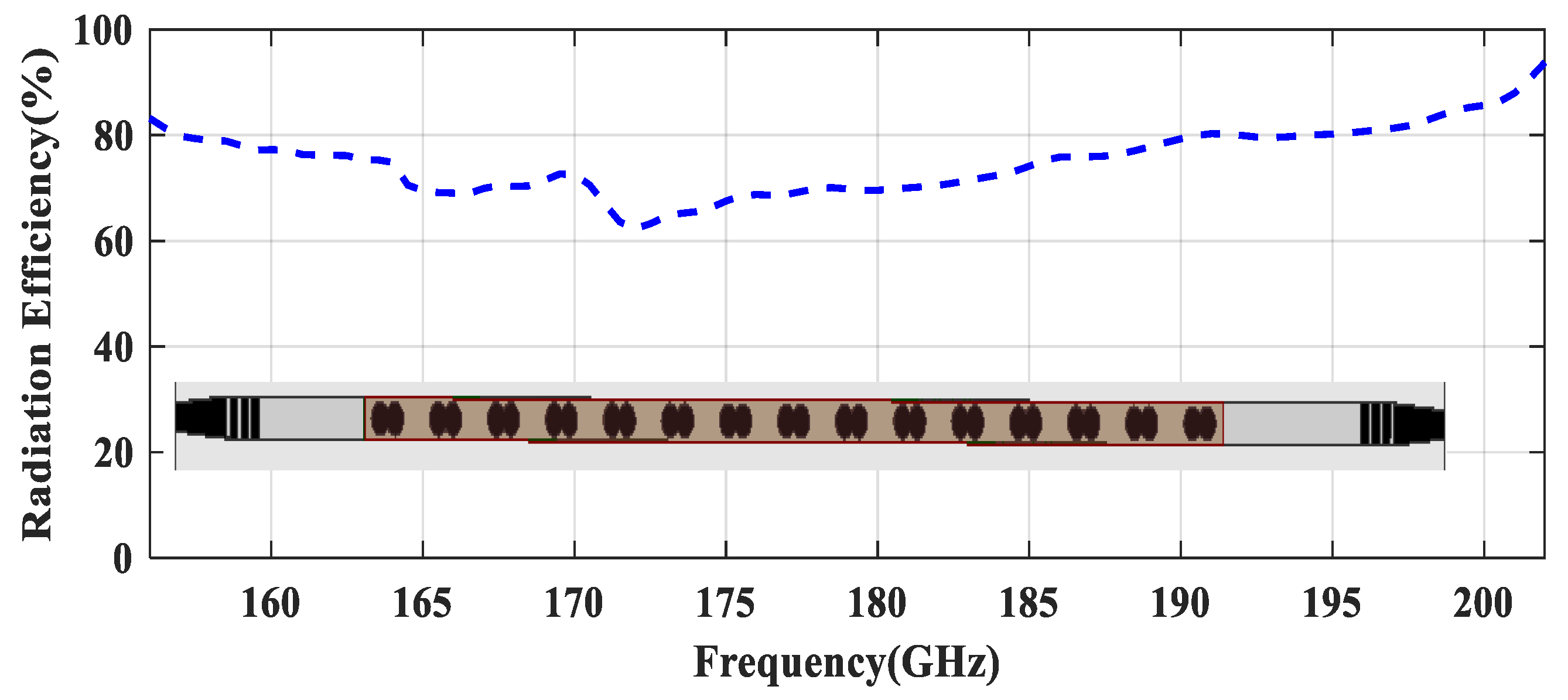
The simulated gain and main beam angles versus frequency is also shown in Figure 6. A precise inspection of this plot reveals that gain increased consistently with frequency, with a slight dip at the broadside radiation point. As can be seen, in the band around 172 GHz, the gain was slightly decreased due to the weaker reflection cancellation leading to a reflected wave at the incident port (OSB effect); however, it was still 13.6 dBi. Furthermore, the gain was consistently varying less than 5 dBi over the working frequency band, varying from 10.5 dBi to 15 dBi. The main beam of the proposed LWA was scanned from −23° to 38° in a frequency range from 157.5 to 201.5 GHz. Accordingly, we were reaching a wide continuous beam scanning range of 61° through the broadside. The simulated radiation efficiency versus frequency is also depicted in Figure 7. As it can be seen from this figure, the proposed antenna ensures the minimum efficiency of 60% with 15 unit cells over the scan frequency range. Table 1 illustrates the comparison between the proposed LWA and previous similar works available in the literature. The proposed antenna had a small length with a relatively high gain and provides a wider beam scanning from the backward region to the forward region.

4. Fabrication and Measurement Challenges

Although the proposed design had a suitable configuration acting as a LWA with superior characteristics at Sub-THz frequencies, its fabrication might have some level of complexity. For example, there would be slight discrepancies between the simulated and measured results due to the unavoidable air gap between the ground plane and the dielectric layer in the fabrication. However, to address this issue, it is recommended to consider a Teflon-like low-permittivity insulating layer such as a 50 µm thick fluorinated ethylene propylene (FEP) copolymer film at the beginning of the design [52,53]. It should be noted that this layer should not be considered too thick in order to achieve a wide single-mode bandwidth. With thermal bonding at 300 °C, the dielectric is attached on the metal without any adhesive. Moreover, achieving low reflection levels at such high frequencies is relatively challenging, as even some minor deviation in the feature sizes or dielectric constant can potentially impact the antenna performance. As a result, a high-precision fabrication method such as micro-dispensed silver paste should be selected [54] for the metal loading in the proposed antenna. Furthermore, measuring the antenna radiation patterns over the full 180-degree range may also be challenging because of technical limitations. Indeed, at angles near to the backfire, many sources of diffraction associated with antenna-feeding effects (waveguide flange, plastic screw, etc.) or effects related to the absorbing materials can modify the radiation pattern at such high frequencies. Additionally, due to the lack of connectors at sub-THz frequencies, most test equipment is waveguide-based, making the transitions essential for the proposed design. In this work, since the microstrip line is used for feeding, a simple inline transition between this and a rectangular waveguide may also be required for the measurement. The transitions to rectangular waveguide were not modeled in the simulation.

5. Conclusions

A novel frequency-scanning antenna with wide beam scanning and consistent gain in the sub-THz frequency range was presented in this paper. The antenna system uses a layered dielectric waveguide, in which a 15-element linear array of radiating overlapped discs was designed to mitigate the OSB problem fed by the mentioned waveguide. The dominant mode of the layered dielectric waveguide is perturbed by the infinite space harmonics generated by two sets of overlapped discs periodically sandwiched between the layers. Specific properties of the proposed design in terms of radiation characteristics, feeding network, and fabrication and measuring challenges were discussed. A gain of 13.6 dBi in the broadside direction was obtained. The antenna demonstrated a good radiation performance over the working frequency band and enabled continuous wide-beam scanning from −23° to 38° through the broadside with the peak gain of 15 dBi. The technique proposed in this work can be easily adapted to realize and implement antennas in the higher mm-wave frequency.

Author Contributions

All authors provided critical feedback and helped shape the research, analysis and manuscript and contributed to the final manuscript. Conceptualization, Y.T.; methodology, Y.T.; investigation, Y.T.; software, Y.T. and M.H.; validation, G.D., Y.T. and M.H.; formal analysis, Y.T.; resources, H.O. and A.L.; data curation, H.O. and A.L.; writing—original draft preparation, Y.T.; writing—review and editing, Y.T. and A.L.; supervision, G.D. and H.O.; project administration, G.D. and H.O. All authors have read and agreed to the published version of the manuscript.

Funding

This research received no external funding.

Conflicts of Interest

The authors declare no conflict of interest.

References

  1. Gomez-Torrent, A.; Garcia-Vigueras, M.; Le Coq, L.; Mahmoud, A.; Ettorre, M.; Sauleau, R.; Oberhammer, J. A Low-Profile and High-Gain Frequency Beam Steering Subterahertz Antenna Enabled by Silicon Micromachining. IEEE Trans. Antennas Propag. 2019, 68, 672–682. [Google Scholar] [CrossRef]
  2. Matsumoto, H.; Watanabe, I.; Kasamatsu, A.; Monnai, Y. Integrated terahertz radar based on leaky-wave coherence tomography. Nat. Electron. 2020, 3, 122–129. [Google Scholar] [CrossRef]
  3. Rikkinen, K.; Kyosti, P.; Leinonen, M.E.; Berg, M.; Parssinen, A. THz Radio Communication: Link Budget Analysis toward 6G. IEEE Commun. Mag. 2020, 58, 22–27. [Google Scholar] [CrossRef]
  4. Kwon, H.; Kim, Y.; Yoon, H.; Choi, D. Selective Audio Adversarial Example in Evasion Attack on Speech Recognition System. IEEE Trans. Inf. Forensics Secur. 2019, 15, 526–538. [Google Scholar] [CrossRef]
  5. Brown, E.R. Fundamentals of Terrestrial Millimeter-Wave and THz Remote Sensing. Int. J. High Speed Electron. Syst. 2003, 13, 995–1097. [Google Scholar] [CrossRef] [Green Version]
  6. Golubiatnikov, G.Y.; Koshelev, M.A.; Tsvetkov, A.I.; Fokin, A.P.; Glyavin, M.Y.; Tretyakov, M.Y. Sub-Terahertz High-Sensitivity High-Resolution Molecular Spectroscopy with a Gyrotron. IEEE Trans. Terahertz Sci. Technol. 2020, 10, 502–512. [Google Scholar] [CrossRef]
  7. Guerboukha, H.; Shrestha, R.; Neronha, J.; Ryan, O.; Hornbuckle, M.; Fang, Z.; Mittleman, D.M. Efficient leaky-wave antennas at terahertz frequencies generating highly directional beams. Appl. Phys. Lett. 2020, 117, 261103. [Google Scholar] [CrossRef]
  8. Agarwal, R.; Agarwal, A.; Dwivedi, A.; Sharma, A. Leaky wave antenna for millimeter wave utilization. J. Phys. Conf. Ser. 2021, 1921, 012026. [Google Scholar] [CrossRef]
  9. Munawar, H.S. Applications of Leaky-wave Antennas: A Review. Int. J. Wirel. Microw. Technol. 2020, 10, 56–62. [Google Scholar] [CrossRef]
  10. Ghalibafan, J.; Hashemi, S.M. Leaky-Wave Centerline Longitudinal Slot Antenna Fed by Transversely Magnetized Ferrite. IEEE Trans. Magn. 2015, 52, 1–4. [Google Scholar] [CrossRef]
  11. Zheng, D.; Lyu, Y.-L.; Wu, K. Transversely Slotted SIW Leaky-Wave Antenna Featuring Rapid Beam-Scanning for Millimeter-Wave Applications. IEEE Trans. Antennas Propag. 2020, 68, 4172–4185. [Google Scholar] [CrossRef]
  12. Ranjan, R.; Ghosh, J. SIW-Based Leaky-Wave Antenna Supporting Wide Range of Beam Scanning through Broadside. IEEE Antennas Wirel. Propag. Lett. 2019, 18, 606–610. [Google Scholar] [CrossRef]
  13. Saghati, A.P.; Mirsalehi, M.M.; Neshati, M.H. A HMSIW Circularly Polarized Leaky-Wave Antenna With Backward, Broadside, and Forward Radiation. IEEE Antennas Wirel. Propag. Lett. 2014, 13, 451–454. [Google Scholar] [CrossRef]
  14. Chen, Y.; Wang, K.; Li, Y.; Long, Y. Periodic Microstrip Leaky Wave Antenna with Double-Sided Shorting Pins and Pairs of Slots. Int. J. Antennas Propag. 2020, 2020, 7101752. [Google Scholar] [CrossRef]
  15. Ros, A.J.M.; Gomez-Tornero, J.L.; Goussetis, G. Planar Leaky-Wave Antenna With Flexible Control of the Complex Propagation Constant. IEEE Trans. Antennas Propag. 2011, 60, 1625–1630. [Google Scholar] [CrossRef]
  16. Grbic, A.; Eleftheriades, G.V. Leaky CPW-based slot antenna arrays for millimeter-wave applications. IEEE Trans. Antennas Propag. 2002, 50, 1494–1504. [Google Scholar] [CrossRef] [Green Version]
  17. Alibakhshikenari, M.; Virdee, B.S.; Khalily, M.; Shukla, P.; See, C.H.; Abd-Alhameed, R.; Falcone, F.; Limiti, E. Beam-scanning leaky-wave antenna based on CRLH-metamaterial for millimetre-wave applications. IET Microw. Antennas Propag. 2019, 13, 1129–1133. [Google Scholar] [CrossRef]
  18. Pozar, D.M. Microwave Engineering, 4th ed.; Wiley: Hoboken, NJ, USA, 2011. [Google Scholar]
  19. Schwering, F.; Peng, S.-T. Design of Dielectric Grating Antennas for Millimeter-Wave Applications. IEEE Trans. Microw. Theory Tech. 1983, 31, 199–209. [Google Scholar] [CrossRef]
  20. Hammad, H.; Antar, Y.; Freundorfer, A.; Sayer, M. A new dielectric grating antenna at millimeter wave frequency. IEEE Trans. Antennas Propag. 2004, 52, 36–44. [Google Scholar] [CrossRef]
  21. Ma, Z.L.; Ng, K.B.; Chan, C.H.; Jiang, L.J. A Novel Supercell-Based Dielectric Grating Dual-Beam Leaky-Wave Antenna for 60-GHz Applications. IEEE Trans. Antennas Propag. 2016, 64, 5521–5526. [Google Scholar] [CrossRef]
  22. Prasad, C.S.; Biswas, A. Dielectric Image Line-Based Leaky-Wave Antenna for Wide Range of Beam Scanning Through Broadside. IEEE Trans. Antennas Propag. 2017, 65, 4311–4315. [Google Scholar] [CrossRef]
  23. Salman, A.O. On the antenna efficiencies for the dielectric leaky-wave antennas with a sinusoidal metallic diffraction grating coupled from the broad and the narrow face of the dielectric. Microw. Opt. Technol. Lett. 2011, 53, 2030–2034. [Google Scholar] [CrossRef]
  24. Prasad, C.S.; Biswas, A.; Akhtar, M.J. Leaky Wave Antenna for Wide Range of Beam Scanning through Broadside in Dielectric Image Line Environment. Microw. Opt. Technol. Lett. 2018, 60, 1707–1713. [Google Scholar] [CrossRef]
  25. Zandamela, A.; Al-Bassam, A.; Heberling, D. Circularly Polarized Periodic Leaky-Wave Antenna Based on Dielectric Image Line for Millimeter-Wave Radar Applications. IEEE Antennas Wirel. Propag. Lett. 2021, 20, 938–942. [Google Scholar] [CrossRef]
  26. Cheng, Y.J.; Guo, Y.; Bao, X.Y.; Ng, K.B. Millimeter-Wave Low Temperature Co-Fired Ceramic Leaky-Wave Antenna and Array Based on the Substrate Integrated Image Guide Technology. IEEE Trans. Antennas Propag. 2013, 62, 669–676. [Google Scholar] [CrossRef]
  27. Patrovsky, A.; Wu, K. Substrate Integrated Image Guide Array Antenna for the Upper Millimeter-Wave Spectrum. IEEE Trans. Antennas Propag. 2007, 55, 2994–3001. [Google Scholar] [CrossRef]
  28. Dey, U.; Tonn, J.; Hesselbarth, J. Millimeter-Wave Dielectric Waveguide-Based Leaky-Wave Antenna Array. IEEE Antennas Wirel. Propag. Lett. 2021, 20, 361–365. [Google Scholar] [CrossRef]
  29. Ostner, H.; Detlerfsen, J.; Jackson, D. Radiation from one-dimensional dielectric leaky-wave antennas. IEEE Trans. Antennas Propag. 1995, 43, 331–339. [Google Scholar] [CrossRef]
  30. Sharma, J.; De, A. Full-Wave Analysis of Dielectric Rectangular Waveguides. Prog. Electromagn. Res. M 2010, 13, 121–131. [Google Scholar] [CrossRef] [Green Version]
  31. Fong, T.; Lee, S. Planar Dielectric Strip Waveguide for Millimeter-Wave Integrated Circuits. In Proceedings of the S-MTT International Microwave Symposium Digest, Atlanta, GA, USA, 12–14 June 1974; Volume 74, pp. 191–194. [Google Scholar] [CrossRef]
  32. Shindo, S.; Itanami, T. Low-Loss Rectangular Dielectric Image Line for Millimeter-Wave Integrated Circuits. IEEE Trans. Microw. Theory Tech. 1978, 26, 747–751. [Google Scholar] [CrossRef]
  33. Lalbakhsh, A.; Afzal, M.U.; Hayat, T.; Esselle, K.P.; Mandal, K. All-metal wideband metasurface for near-field transformation of medium-to-high gain electromagnetic sources. Sci. Rep. 2021, 11, 9421. [Google Scholar] [CrossRef]
  34. Mirmozafari, M.; Zhang, Z.; Gao, M.; Zhao, J.; Honari, M.; Booske, J.; Behdad, N. Mechanically Reconfigurable, Beam-Scanning Reflectarray and Transmitarray Antennas: A Review. Appl. Sci. 2021, 11, 6890. [Google Scholar] [CrossRef]
  35. Goudarzi, A.; Honari, M.M.; Gharaati, A.; Mirzavand, R. A Cylindrical Coaxial-fed Resonant Cavity Antenna with Off-axis Beaming for 5G Applications. In Proceedings of the 15th European Conference on Antennas and Propagation (EuCAP), Düsseldorf, Germany, 22–26 March 2021; pp. 1–4. [Google Scholar] [CrossRef]
  36. Afzal, M.U.; Matekovits, L.; Esselle, K.P.; Lalbakhsh, A. Beam-Scanning Antenna Based on Near-Electric Field Phase Transformation and Refraction of Electromagnetic Wave Through Dielectric Structures. IEEE Access 2020, 8, 199242–199253. [Google Scholar] [CrossRef]
  37. Al-Amoodi, K.; Mirzavand, R.; Honari, M.M.; Melzer, J.; Elliott, D.; Mousavi, P. Compact circularly-polarized SIW edge-radiating antenna for beamsteering in 5G mobile devices. In Proceedings of the 2018 IEEE International Symposium on Antennas and Propagation & USNC/URSI National Radio Science Meeting, Boston, MA, USA, 8–13 July 2018; pp. 1771–1772. [Google Scholar]
  38. Rahmani, M.H.; Deslandes, D. Backward to forward scanning periodic leaky-wave antenna with wide scanning range. IEEE Trans. Antennas Propag. 2017, 65, 3326–3335. [Google Scholar] [CrossRef]
  39. Lalbakhsh, A.; Esselle, K.P. Directivity improvement of a fabry-perot cavity antenna by enhancing near field characteristic. In Proceedings of the 17th International Symposium on Antenna Technology and Applied Electromagnetics (ANTEM), Montréal, QC, Canada, 10–13 July 2016; pp. 1–2. [Google Scholar]
  40. Nguyen-Trong, N.; Kaufmann, T.; Hall, L.; Fumeaux, C. Optimization of leaky-wave antennas based on non-uniform HMSIW. In Proceedings of the 2015 IEEE MTT-S International Conference on Numerical Electromagnetic and Multiphysics Modeling and Optimization (NEMO), Ottawa, ON, Canada, 11–14 August 2015; pp. 1–4. [Google Scholar]
  41. Lalbakhsh, A.; Afzal, M.U.; Esselle, K.P.; Smith, S. Design of an artificial magnetic conductor surface using an evolutionary algorithm. In Proceedings of the International Conference on Electromagnetics in Advanced Applications (ICEAA), Verona, Italy, 11–15 September 2017; pp. 885–887. [Google Scholar] [CrossRef]
  42. Zvolensky, T.; Ala-Laurinaho, J.; Simovski, C.R.; Räisänen, A.V. A Systematic Design Method for CRLH Periodic Structures in the Microwave to Millimeter-Wave Range. IEEE Trans. Antennas Propag. 2014, 62, 4153–4161. [Google Scholar] [CrossRef] [Green Version]
  43. Jamshidi, M.; Lalbakhsh, A.; Mohamadzade, B.; Siahkamari, H.; Mousavi, S.M.H. A novel neural-based approach for design of microstrip filters. AEU-Int. J. Electron. Commun. 2019, 110, 152847. [Google Scholar] [CrossRef]
  44. Lalbakhsh, P.; Zaeri, B.; Lalbakhsh, A.; Fesharaki, M.N. Antnet with reward-penalty reinforcement learning. In Proceedings of the 2nd International Conference on Computational Intelligence, Communication Systems and Networks, Liverpool, UK, 28–30 July 2010; pp. 17–21. [Google Scholar]
  45. Bhartia, P.; Bahl, I. Millimeter Wave Engineering and Applications; Wiley: New York, NY, USA, 1984. [Google Scholar]
  46. Liu, J. Periodic Leaky-Wave Antennas Based on Microstrip-Fed Slot Array with different Profile Modulations for Suppressing Open Stopband and n = −2 Space Harmonic. IEEE Trans. Antennas Propag. 2021, 1–13. [Google Scholar] [CrossRef]
  47. Guglielmi, M.; Jackson, D. Broadside radiation from periodic leaky-wave antennas. IEEE Trans. Antennas Propag. 1993, 41, 31–37. [Google Scholar] [CrossRef]
  48. Collin, R.E. Antenna Theory [by] Robert E. Collin [and] Francis J. Zucker (Inter-University Electronics Series); McGraw-Hill: New York, NY, USA, 1969; Volume 7. Available online: https://nla.gov.au/nla.cat-vn2086565 (accessed on 4 September 2021).
  49. Prasad, C.S.; Biswas, A. Broadband Planar Transition to Dielectric Image Line by Substrate Truncated Microstrip Line for Millimeter-Wave Circuit Integration. IEEE Microw. Wirel. Compon. Lett. 2017, 27, 533–535. [Google Scholar] [CrossRef]
  50. Ghasemi, A.; Laurin, J.-J. A Continuous Beam Steering Slotted Waveguide Antenna Using Rotating Dielectric Slabs. IEEE Trans. Antennas Propag. 2019, 67, 6362–6370. [Google Scholar] [CrossRef] [Green Version]
  51. Sarabandi, K.; Jam, A.; Vahidpour, M.; East, J. A Novel Frequency Beam-Steering Antenna Array for Submillimeter-Wave Applications. IEEE Trans. Terahertz Sci. Technol. 2018, 8, 654–665. [Google Scholar] [CrossRef]
  52. Patrovsky, A.; Wu, K. Substrate integrated image guide (SIIG)—A low-loss waveguide for millimetre-wave applications. In Proceedings of the 2005 European Microwave Conference, Paris, France, 4–6 October 2005; Volume 2. [Google Scholar] [CrossRef]
  53. Fang, P.; Wang, F.; Wirges, W.; Gerhard, R.; Basso, H.C. Three-layer piezoelectrets from fluorinated ethylene-propylene (FEP) copolymer films. Appl. Phys. A Mater. Sci. Process. 2010, 103, 455–461. [Google Scholar] [CrossRef]
  54. Liang, M.; Xin, H. Three-Dimensionally Printed/Additive Manufactured Antennas; Springer: Singapore, 2016; pp. 661–697. [Google Scholar] [CrossRef]
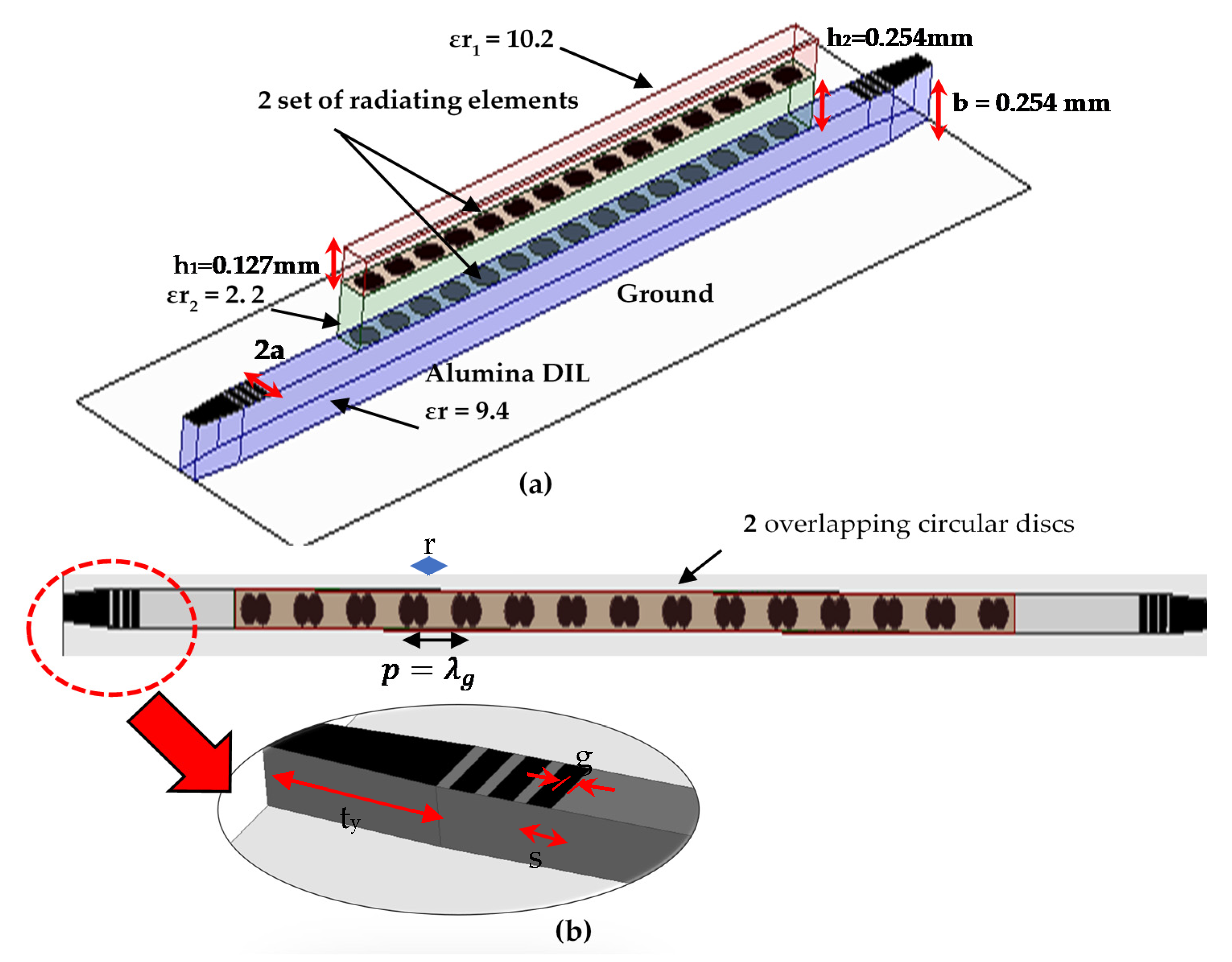
Figure 1. Layout of the proposed LWA. (a) Cross-sectional view of the array and (b) a top view of the structure along with the feeding network; 2a = 0.3, p = 0.8, ty = 0.7, S = 0.12, g = 0.1, r = 0.1 mm, b = 0.254, h2 = 0.254, h1 = 0.127, (Unit: mm).
Electronics 10 02172 g001
Figure 2. Dispersion curve of the optimized unit-cell with dimensions indicated in Figure 1.
Electronics 10 02172 g002
Figure 3. Frequency variation of S-parameters of the proposed antenna for two type of unit-cells; (a) one circular disc, (b) two overlapped circular discs with a center-to-center spacing of λg/4.
Electronics 10 02172 g003
Figure 4. Simulated radiation patterns in the E-plane at different frequencies.
Electronics 10 02172 g004
Figure 5. Simulated co- and cross-polar E-plane and H-plane radiation patterns at the broadside frequency of 172 GHz.
Electronics 10 02172 g005
Figure 6. Simulated main beam angles and gain versus frequency.
Electronics 10 02172 g006
Figure 7. Simulated radiation efficiency versus frequency.
Electronics 10 02172 g007
Table 1. Performance comparison with the prior literature.
Frequency Range
(GHz)
Scanning
Range (Degree)
Peak Gain
(dBi)
Broadside RadiationSizeEfficiency (%)
[25]75–85−10°–8°12.7Yes11.1 λ0Not mentioned
[50]55 to 67Forward only
4°–18°
6No12 λ079
[51]230–245−25°–25°29Yes8 λ055
[1]220–300Backward only
−75°–−30°
28.5No10 λ075.8
[27]86–106−31°–10°11Yes6 λ058
[26]58–67Forward only
7°–38°
11.7No2.6 λ085
This work157.5–206−23°–38°15Yes6.9 λ060
Publisher’s Note: MDPI stays neutral with regard to jurisdictional claims in published maps and institutional affiliations.