Article

Voltage Regulation of an Isolated DC Microgrid with a Constant Power Load: A Passivity-based Control Design

by
Guillermo Luciano Magaldi
1,*,
Federico Martin Serra
1,
Cristian Hernán de Angelo
2,
Oscar Danilo Montoya
3,4,* and
Diego Armando Giral-Ramírez
5
1
Laboratorio de Control Automático (LCA), Facultad de Ingeniería y Ciencias Agropecuarias, Universidad Nacional de San Luis—CONICET, Villa Mercedes, San Luis 5730, Argentina
2
Grupo de Electrónica Aplicada (GEA), Instituto de Investigaciones en Tecnologías Energéticas y Materiales (IITEMA)—CONICET, Facultad de Ingeniería, Universidad Nacional de Río Cuarto, Río Cuarto, Córdoba 5800, Argentina
3
Facultad de Ingeniería, Universidad Distrital Francisco José de Caldas, Bogotá 110231, Colombia
4
Laboratorio Inteligente de Energía, Universidad Tecnológica de Bolívar, Cartagena 131001, Colombia
5
Facultad Tecnológica, Universidad Distrital Francisco José de Caldas, Bogotá 110231, Colombia
*
Authors to whom correspondence should be addressed.
Electronics 2021, 10(17), 2085; https://doi.org/10.3390/electronics10172085
Submission received: 8 August 2021 / Revised: 24 August 2021 / Accepted: 26 August 2021 / Published: 28 August 2021

Abstract

:
Passivity-based nonlinear control for an isolated microgrid system is proposed in this paper. The microgrid consists of a photovoltaic array and a battery energy storage connected to a point of common converters, supplying a constant power load. The purpose of this control strategy is to maintain the output direct current voltage in its reference value under load variations, improving battery interaction. The system is represented by its state space averaged model and the proposed controller is designed using the interconnection and damping assignment strategy, which allows obtaining controller parameters while ensuring the closed-loop system stability. The unknown constant power load is estimated using an observer based on the energy function of the system. The behavior of the proposed control strategy is validated with simulation and experimental results.

1. Introduction

Direct current (DC) microgrids (MGs) are being increasingly used in conjunction with the classic electric power system to meet energy demand problems [1,2]. In addition, MGs are also used as isolated systems in several applications such as in rural electrical systems, aircraft, and ships, among others, integrating renewable energy sources and energy storage units through electronic power converters [3,4,5]. A typical configuration of an isolated MG is shown in Figure 1, where the array of photovoltaic (PV) panels and battery energy storage (BES) unit are connected to the point of common converters or DC link through DC–DC converters. Different loads, such as local DC loads or another MGs with different voltage level are also connected to the DC link [4,6,7,8].
The control of a MG is generally based on determining the power that must be delivered by each source, including storage elements, to feed a local demand. This implies the need for a primary controller for each power converter and a secondary controller to manage the system energy [9,10]. Depending on the size and utility of the MG, other levels of controller may be necessary, such as demand side management, achieving total control, and improving the efficiency of the entire system [11,12]. Generally, the aim of a MG primary controller is to keep the voltage, current, or power within a reference value fixed by the secondary controller, both working as a global controller while rejecting system disturbances, such as load changes or variations, on PV array conditions. In popular applications based on isolated systems such as the one shown in Figure 1, the DC-link MG1 voltage is regulated on a fixed value using the available storage [13,14,15]. Therefore, when only a BES is used in the system, the greatest challenge is to design a controller to improve the desired performance without neglecting the battery interaction during the mode transitions in order to preserve its lifespan [14,15,16].
However, some types of loads connected on the DC link can produce a negative-impedance effect, generating system instability and loss of regulation on the feeder system [3,17,18]. Moreover, other effects such as high stress and temperature rise in power converter elements may occur, reducing its performance and lifetime [19]. These types of loads are usually power electronic converters connected in cascade with different output voltage levels or operating conditions and are called constant power loads (CPLs) [20,21,22].
To solve the aforementioned problems produced by CPLs, different approaches have been proposed in the existing literature. These approaches are based on system modification by adding passive elements to minimize these effects or by a control action designed to damp oscillations [18], such as active damping [23], backstepping [6], and feedback linearization [24], among others.
Passivity-based control (PBC) is another kind of strategy used to control power converters due to its simplicity, efficiency, and ease of implementation as compared with other nonlinear control techniques [19,25]. One of the most used PBC strategies for power converters is the interconnection and damping assignment (IDA) method [26]. The design of the controllers using IDA-PBC consists of modify the energy function of the system in order to obtain error dynamics that guarantee its convergence to zero [27,28]. The most outstanding features of IDA-PBC are its stability and the simplicity in parameter determination, even for global controllers with multiple converters. The most popular applications of this approach to solve the CPL effect shows the stability and performance on DC–DC power converters allocated in a DC MG system [7,10,19,25,29,30]. On isolated MGs, IDA-PBC was applied as secondary controller in [31] and as a global controller in [32], but considering only linear and nonlinear loads.
Based on the described problem, this paper proposes a controller based on IDA-PBC to regulate the DC-link voltage on a MG when a CPL is connected to it. The main contributions of this work are summarized as follows:
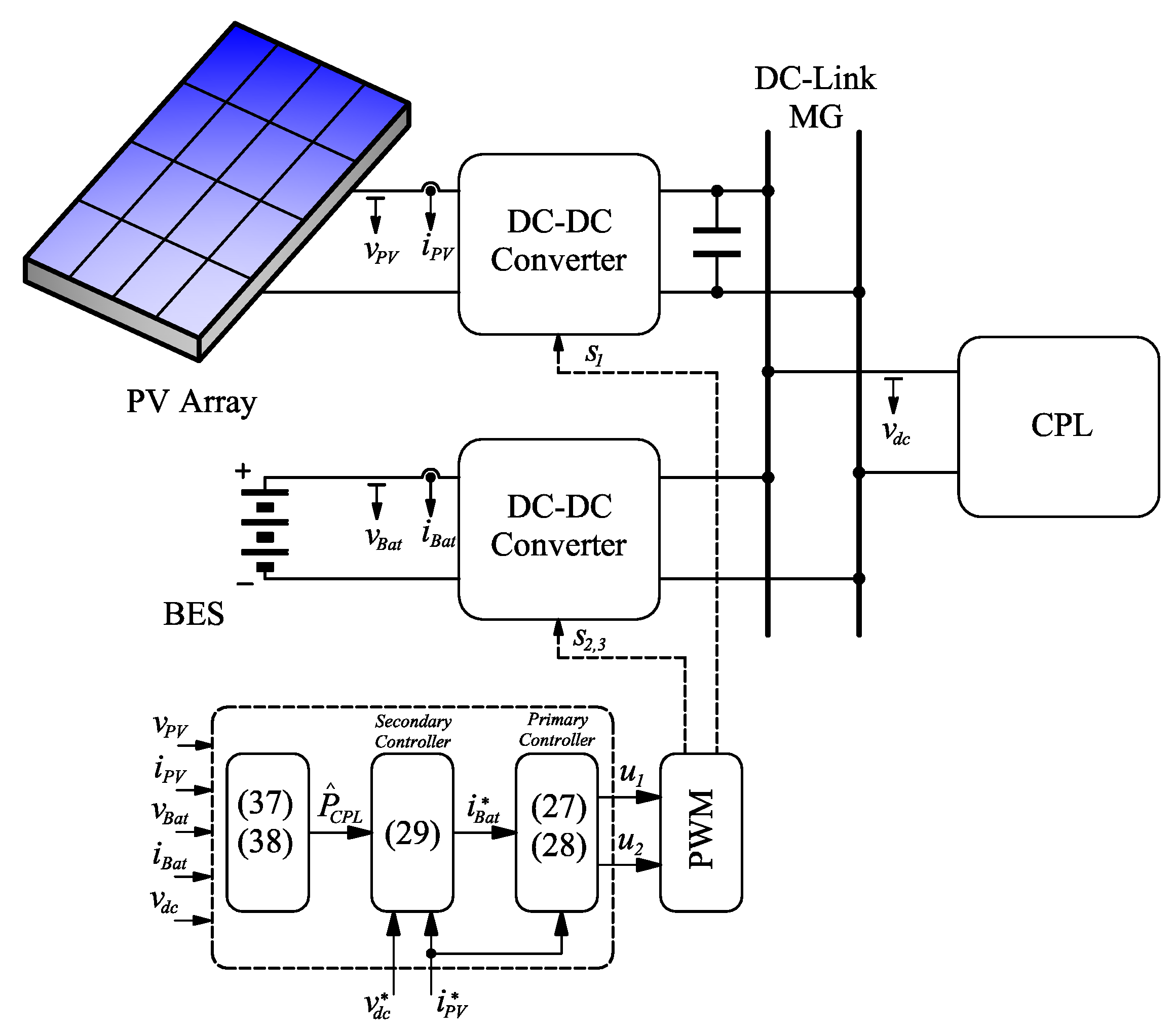
  • Design of a global controller (primary and secondary controller included) using a unique nonlinear approach to satisfy the desired performance of MG under CPL effects.
  • Estimation of the unknown load from an energy-based observer, reducing the total number of sensors.
  • Simulations and experimental validation of the designed controller using a realistic MG prototype and comparison with a classical technique.
This paper is organized as follows: Section 2 shows a detailed description and modeling of the considered MG, Section 3 describes the controller approach, Section 4 presents the simulation and experimental results and in Section 5 some conclusions are drawn.

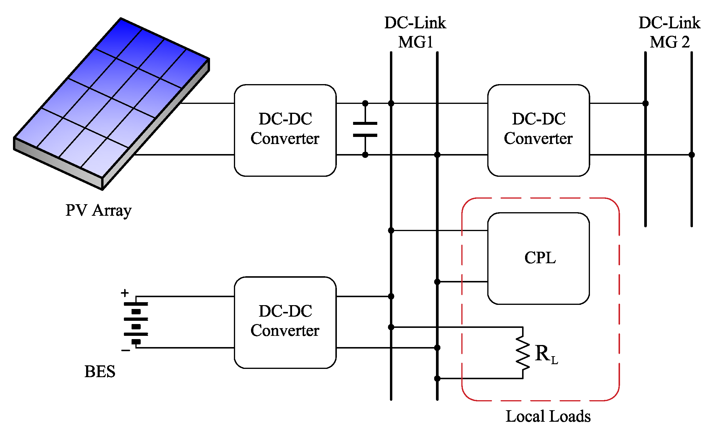
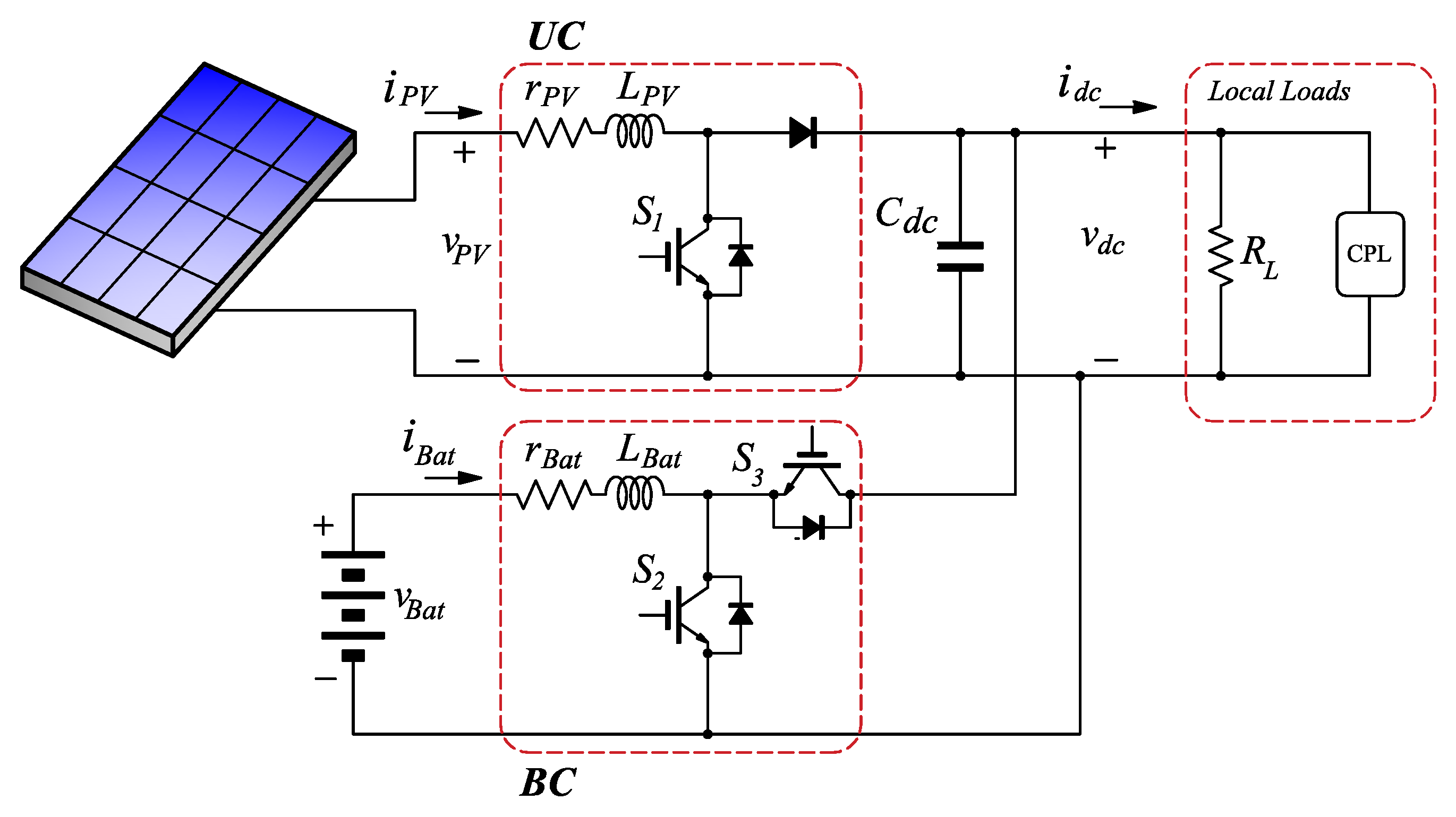
2. Modeling of the Microgrid

The electric circuit of the MG presented in Figure 1 is shown in detail in Figure 2. It is assumed that only local loads are connected. PV array and BES are connected via unidirectional (UC) and bidirectional (BC) DC–DC boost converters, respectively.
From the scheme of Figure 2, the averaged state-space model can be expressed as follows:
L P V i ˙ P V = r P V i P V ( 1 u 1 ) v d c + v P V ,
C d c v ˙ d c = ( 1 u 1 ) i P V + u 2 i B a t v d c R L P C P L v d c ,
L B a t i ˙ B a t = u 2 v d c r B a t i B a t + v B a t .
where v d c is the DC-link voltage; u 1 and u 2 are the control signals of UC and BC; C d c is the DC-link capacitance; L P V and L B a t are the inductances between the energy sources and the converters, with resistances r P V and r B a t , which represent the internal resistance of each inductor and the losses in the power converters; v P V , v B a t , i P V , and i B a t are the voltages and currents in the PV array and in the battery bank, respectively; R L is the load resistance; and P C P L is the power of the CPL.
The design of the controller is performed using IDA-PBC. With this aim, the system (1)–(3) must be represented as a port-Hamiltonian (pH) system,
x ˙ = J ( x , u ) R ( x ) H ( x ) x + g ( x , u ) e ,
y = g T ( x , u ) H ( x ) x ,
where x is the state vector, u is the control vector, J ( x , u ) = J T ( x , u ) is the interconnection matrix, R ( x ) = R T ( x ) 0 is the damping matrix, H ( x ) is the energy function of the system, g ( x , u ) is the input matrix, e is the vector of external sources, and y is the output vector [27].
The state and control vectors, and the interconnection and damping matrices are given by
x = L P V i P V C d c v d c L B a t i B a t T ,
u = u 1 u 2 T ,
J ( u ) = 0 ( 1 u 1 ) 0 ( 1 u 1 ) 0 u 2 0 u 2 0 ,
R ( x ) = r P V 0 0 0 1 R L + P C P L v d c 2 0 0 0 r B a t ,
The input matrix, the vector of external sources and the output vector are given by
g = 1 0 0 0 1 0 0 0 1 ,
e = v P V 0 v B a t T ,
y = i P V 0 i B a t T .
The energy function of the system, H ( x ) , is given by
H ( x ) = L P V i P V 2 2 + C d c v d c 2 2 + L B a t i B a t 2 2 .
From (13), the gradient of energy function is calculated as follows:
H ( x ) x = i P V v d c i B a t T .

3. IDA-PBC Control

The aim of the proposed control strategy is to regulate the DC-link voltage in a constant value, even when changes in the load conditions may appear. The most unfavorable case is when a pure constant power load is connected to the system ( R L ) [6,23]. Moreover, it is assumed that all the existing elements are insufficient to passivize the CPL effects [19].
The design of the controller consists on ensuring that the state variables of the system (4) reach the reference vector,
x = L P V i P V C d c v d c L B a t i B a t T .
To this end, we propose a control law u = β ( x ) , such that the dynamics of the closed-loop system is given by a new pH system,
x ˙ = J d ( x , u ) R d ( x ) H d ( x ) x ,
and x is a minimum of H d ( x ) ,
H d ( x ) x x = x = 0 , 2 H d ( x ) x 2 x = x > 0 .
Here, H d ( x ) is the desired energy function for the closed-loop system, and J d ( x , u ) and R d ( x ) are the desired interconnection and damping matrices,
J d ( x , u ) = J ( x , u ) + J a ( x , u ) , R d ( x ) = R ( x ) + R a ( x ) .
From [27], and given J ( x , u ) , R ( x ) , H ( x ) , g ( x , u ) , and the desired equilibrium point, x , if we can find functions β ( x ) , J a ( x , u ) , R a ( x ) , and a vector function K ( x ) satisfying
J ( x , β ( x ) ) + J a ( x , β ( x ) ) R ( x ) + R a ( x ) K ( x ) = J a ( x , β ( x ) ) R a ( x ) H ( x ) x + g ( x , β ( x ) ) e ,
and the conditions proposed in [27], (16) will be a pH system where
H d ( x ) : = H ( x ) + H a ( x ) , H a ( x ) x : = K ( x ) .
In this case, x will be a (locally) stable equilibrium point in a closed loop. Matrices J a ( x , u ) and R a ( x ) are used here to synthetize the proposed control strategy.
In order to make the system states ( x ) tend to their reference value ( x ) asymptotically, H d ( x ) is chosen as a Lyapunov function,
H d ( x ) = 1 2 ( ϵ T P 1 ϵ ) ,
such that (17) is fulfilled. Here, ϵ = x x and matrix P is given by
P = L P V 0 0 0 C d c 0 0 0 L B a t .
The time derivative of H d ( x ) is
H d ˙ ( x ) = ϵ T P 1 R d P 1 ϵ < 0 .
Therefore, R d ( x ) must be positive definite to guarantee the error convergence to zero. With this aim, the elements of R a ( x ) are selected as follows:
R a ( x ) = R 1 0 0 0 R 2 0 0 0 R 3 ,
with R 1 > 0 , R 2 = 1 r 2 P C P L v d c 2 > 0 , and R 3 > 0 , all in [ Ω ] .
Elements of J a ( x , u ) can be selected with the aim of canceling the undesired coupling between the state variables while maintaining coupling in those variables that allow dealing with systems with more control variables than control actions [33]. In this case, J a ( x , u ) is selected as follows:
J a ( u ) = 0 ( 1 u 1 ) 0 ( 1 u 1 ) 0 u 2 0 u 2 0 .
Using (18)–(20), the following partial differential equation is obtained:
J ( β ( x ) ) R H a ( x ) x = J a ( β ( x ) ) R a H d ( x ) x + g e .
Solving (26) the control laws for both converters gives
u 1 = 1 r P V i P V + R 1 ( i P V i P V ) + v P V v d c ,
u 2 = r B a t i B a t + R 3 ( i B a t i B a t ) + v B a t v d c ,
while i B a t can be calculated from (26) and (28) considering i B a t = i B a t ,
i B a t = 1 2 v B a t r B a t ± v B a t r B a t 2 4 Δ ,
with
Δ = v d c r B a t P C P L v d c ( 1 u 1 ) i P V 1 r 2 ( v d c v d c ) .
The elements of x are selected to achieve the control objectives and fixed by a secondary level controller. The reference of the DC-link voltage is selected as v d c = V d c (constant), i B a t comes from (29), and i P V is obtained from a maximum power point tracker (MPPT) algorithm such as an incremental conductance (IC) algorithm [9,34].
Since control Equations (27)–(28) are dependent on system parameters, some uncertainties and unmodeled effects may affect the performance of the proposed controller while also producing steady state error in the DC-link voltage. To eliminate this error, an integral action can be added as in [35]. Thus, Δ in (29) is replaced by Δ i ,
Δ i = Δ v d c r B a t K i ( v d c v d c ) d t ,
where K i is the integrator gain. It can be chosen to eliminate the steady state error without affecting the chosen dynamics and the overshoot of the response. With this controller, the error dynamics results in
ϵ ˙ i P V = r P V + R 1 L P V ϵ i P V ,
ϵ ˙ v d c = R 2 C d c ϵ v d c ,
ϵ ˙ i B a t = r B a t + R 3 L B a t ϵ i B a t .
From (32)–(34), the values of R 1 , R 2 and R 3 can be calculated in order to obtain the desired convergence speed for the error in each state variable.

Load Power Estimation

In order to implement the proposed controller, voltages and currents in the system must be measured. In addition, the calculation of the battery current reference, (29), requires knowledge of the power value of the CPL, P C P L .
To ensure an exact value of such power while avoiding the effects of load variations in the mentioned assumption and parameter uncertainty, the use of a current sensor and the calculus of the power using P C P L = v d c i d c is a popular and reliable method. However, this approach is expensive in some cases because more sensors are added to the system. Thus, the use of estimators or observers may be an inexpensive solution to obtain the load power value. Among the different types of estimators, those that are nonlinear, such as high-gain observers [24] or I&I [30], present good dynamic response and zero steady state estimation error for the load power.
In this work, since the proposed controller is derived from an energy-based strategy, a new energy-based observer is proposed to estimate the load power, taking advantage of such representation.
From the energy function (13), its time derivative can be calculated as follows:
H ˙ ( x ) = L P V i P V i ˙ P V + C d c v d c v ˙ d c + L B a t i B a t i ˙ B a t .
Using (1)–(3) results in
H ˙ ( x ) = v P V i P V + v B a t i B a t r P V i P V 2 r B a t i B a t 2 P C P L
Expression (36) shows the different powers involved in the system: the power delivered from the sources (PV panels and battery bank), the power dissipated by resistive elements, and the power extracted by the load.
Therefore, it is possible to build an observer using (36) as follows:
H ^ ˙ ( x ) = v P V i P V + v B a t i B a t r P V i P V 2 r B a t i B a t 2 P ^ C P L γ 1 [ H ( x ) H ^ ( x ) ]
P ^ ˙ C P L = γ 2 [ H ( x ) H ^ ( x ) ]
where P ^ C P L is the estimated load power, and γ 1 and γ 2 are the gains designed to regulate the dynamical behavior of the estimated variable. The dynamics must be fast enough to ensure the convergence of the estimated variable in a small time compared with the control dynamics. The estimation errors of P C P L and H ( x ) are given by
ϵ P C P L = P C P L P ^ C P L ,
ϵ H ( x ) = H ( x ) H ^ ( x ) ,
and its dynamic results,
ϵ ˙ P C P L = P ^ ˙ C P L = γ 2 ϵ H ( x ) ,
ϵ ˙ H ( x ) = H ˙ ( x ) H ^ ˙ ( x ) = ϵ P C P L γ 1 γ 2 ϵ ˙ P C P L ,
Expressions (41) and (42) show that any [ γ 1 , γ 2 ] > 0 , both in [1/s] with condition γ 2 > γ 1 , ensure the convergence of the error to zero.
The control block diagram of the isolated MG configuration with the proposed IDA-PBC and energy-based observer is given in Figure 3.

4. Results

In order to evaluate the performance of the proposed controller for the considered system under different conditions, simulations and experimental tests were carried out. A comparison with a classical proportional integral (PI) controller was also included. The structure of the PI controller is the one proposed in [13], and the gains were selected to obtain a similar convergence speed as the controller proposed in this work. Moreover, in all the tests, the PV array delivers its maximum power.

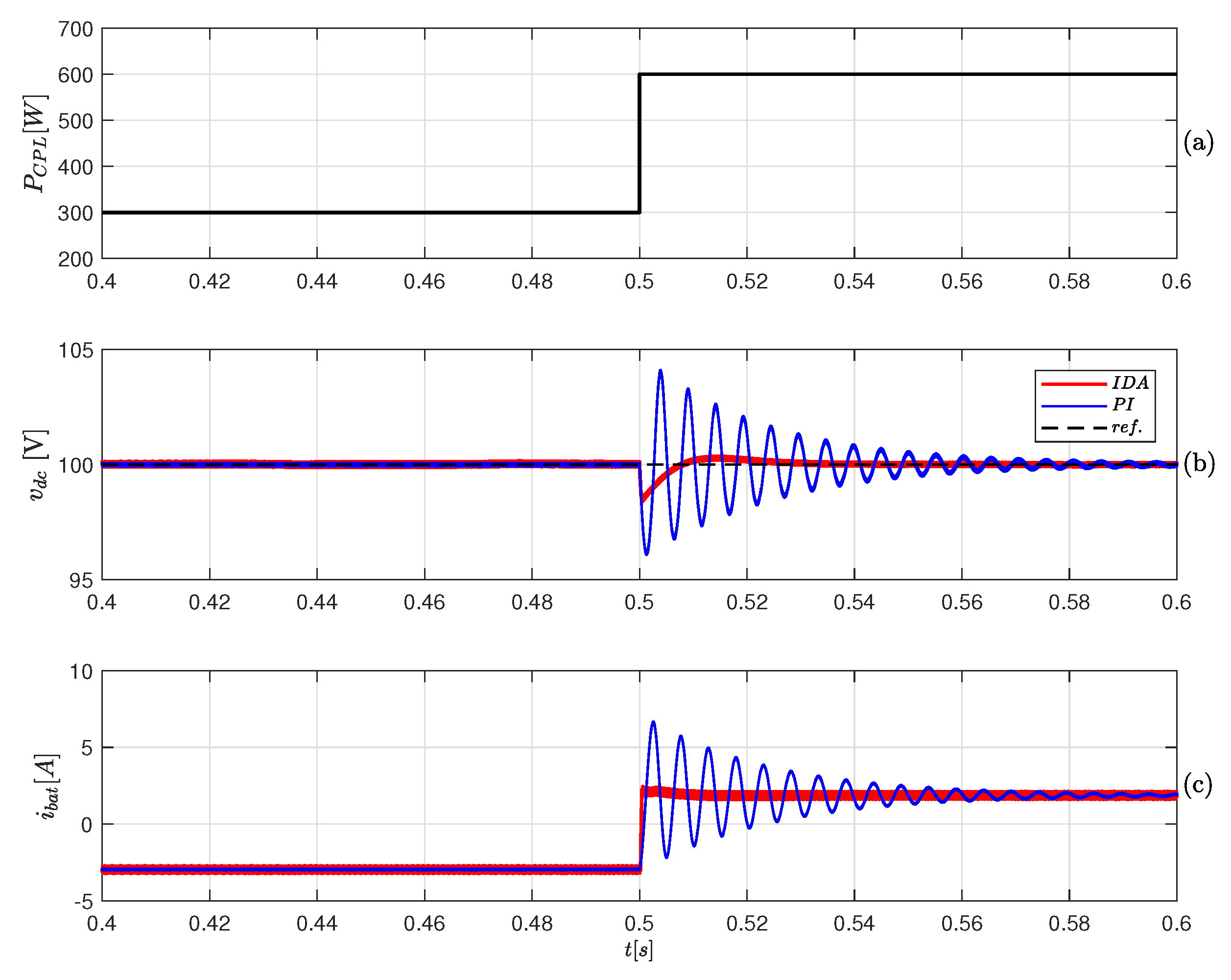
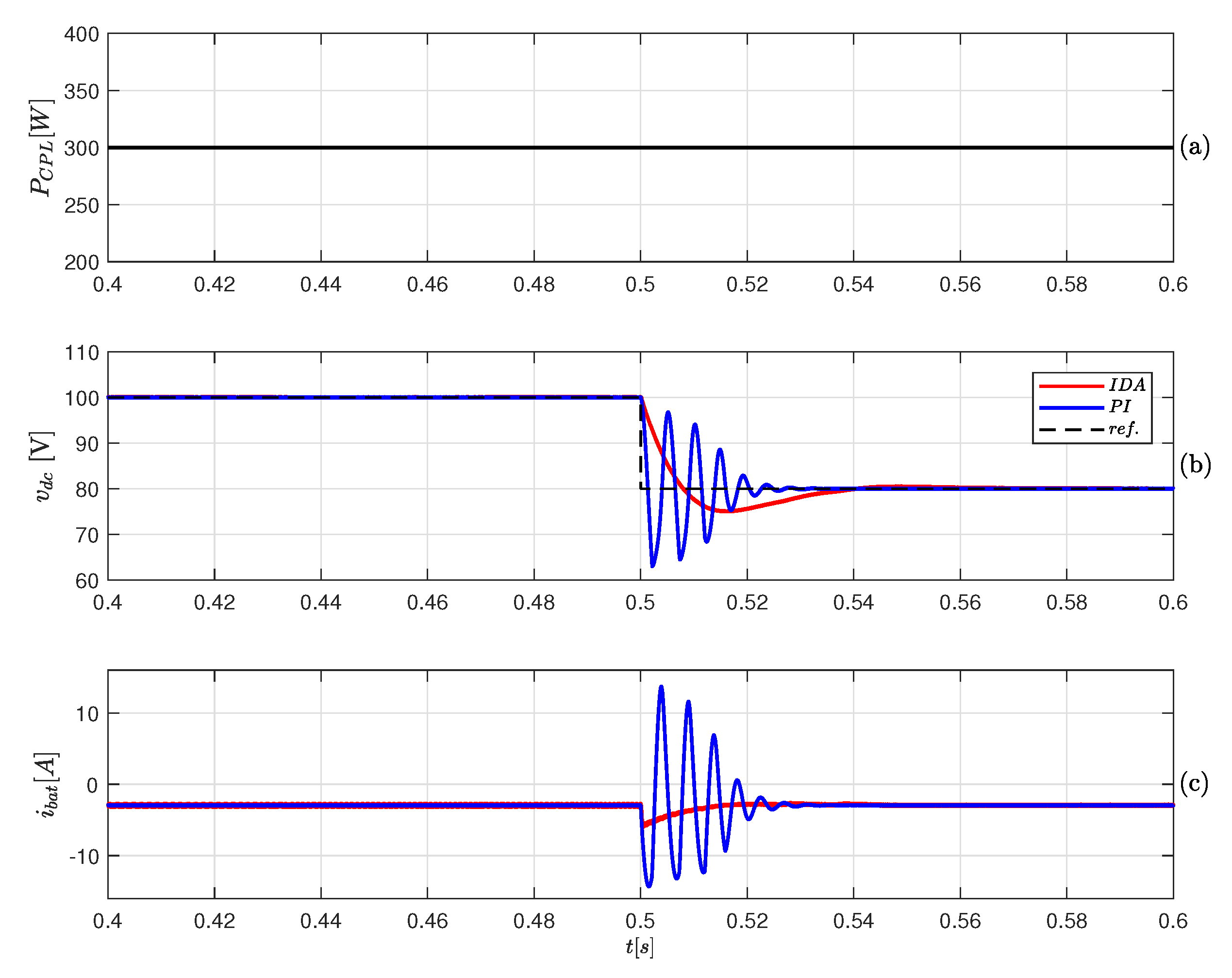
4.1. Simulation Results

The system of Figure 2 and the controller proposed in Section 3 are tested using the Simscape toolbox of Simulink, including losses in the power converter, parasitic elements, and switching effects. All tests where performed using fixed step and a sampling time comparable with the behavior of the actual controller. Table 1 shows the specifications of the system, sources of the MG, and the considered CPL. To ensure the convergence speed for the error of v d c is lower than 40 ms, the parameters for the proposed controller are selected as R 1 = 10 Ω , R 2 = 0.08 Ω , R 3 = 80 Ω , and K i = 2 .
In order to evaluate the effect of γ 2 for a fixed value of γ 1 in the estimation stage, different results are shown in Figure 4 for a step change in the CPL value.
From the previous analysis, γ 2 = 9 × 10 8 is chosen for the following tests.
Figure 5 shows the evolution of the DC-link voltage and current of BES when a load change occurs. A comparison between the proposed IDA-PBC and the PI controller is shown. The reference voltage is fixed at v d c = 100 V, and a load change is performed from 300 to 600 W at t = 0.5 s (see Figure 5a). In Figure 5b, the DC-link voltage (solid line) with its reference (dashed line) are shown, while Figure 5c presents the battery current, i B a t . It can be seen that both controllers allow regulating the mean value of the DC-link voltage, but the PI controller presents a greater overshoot and oscillations when it is adjusted for the same convergence speed as the IDA-PBC. These oscillations are produced by the negative impedance effect introduced by the CPL, affecting the DC-link voltage regulation and, therefore, the BES current [6].
Figure 6 shows the performance of the MG when a change in v d c from 100 to 80 V is requested at t = 0.5 s. In this test, the value of CPL is fixed at 300 W, as shown in Figure 6a. Figure 6b shows the DC-link voltage, v d c , (solid line) with its reference (dashed line), and Figure 6c shows the BES current. Both controllers regulate the DC-link voltage, producing a proportional increase in the load current. As the feeding load does not change, the remaining power is used for charging the battery bank in this test (Figure 6c). However, undesired oscillations are produced in the DC-link voltage and BES current with the PI controller when the voltage reference is changed. Such effect is also due to the negative-impedance behavior of the CPL.

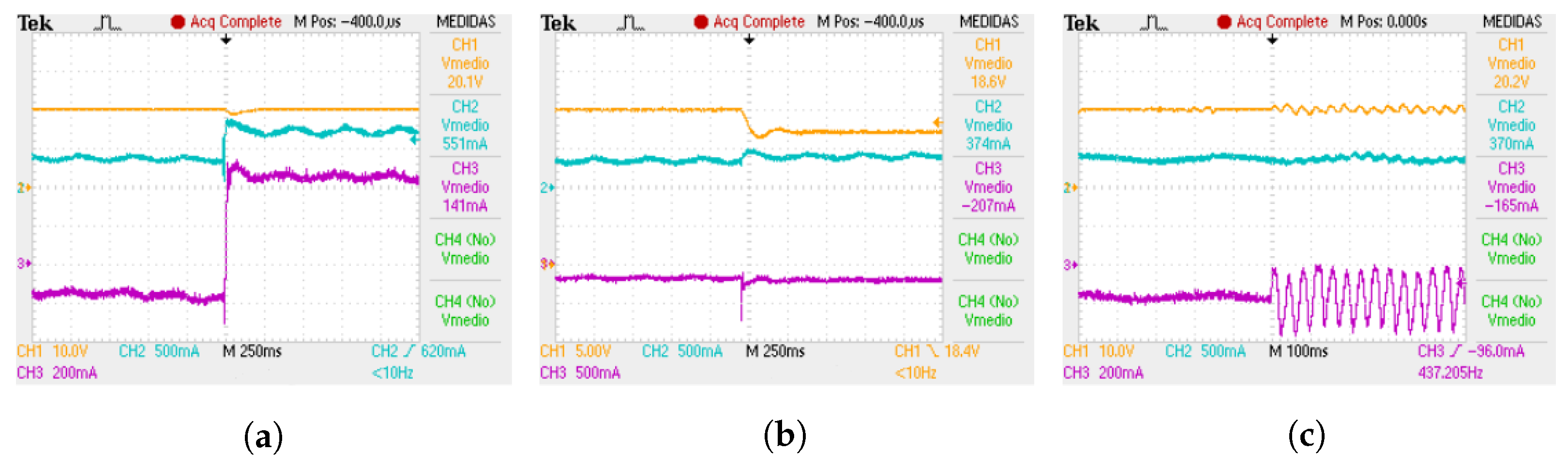
4.2. Experimental Results

Experimental tests were performed using a laboratory prototype with two DC–DC converters constructed using SiC MOSFETs and the necessary passive components. The controller was implemented in a TMS320F28335 Digital Signal Controller (DSC) of Texas Instrument. The CPL is composed by a DC–DC buck converter with an output voltage control and a resistive load.
The power of the PV array is 12 W and a 12 V–7 Ah lead acid battery was used. DC-link voltage reference v d c was fixed at 20 V. Figure 7a shows the behavior of the DC-link voltage and the measured currents of the system when the CPL changes from 7 to 14 W. It can be observed that the battery is being charged when the CPL is 7 W and it is discharged when the CPL is 14 W. The change of value of the CPL is visualized by measuring the load current. The DC-link voltage is regulated in its reference value under the transition without oscillations and, hence, the battery current presents a similar response.
The test for a change in v d c from 20 to 17 V with a fixed value of CPL at 7 W is shown in Figure 7b. It can be observed that the proposed controller allows regulating v d c , while the load current i d c is increased proportionally due to the CPL load having a fixed value. In this situation, i b a t remains constant and under the charge mode, without oscillations.
In Figure 7c, the behavior of the MG can be observed when a change of the controller is made, being v d c = 20 V, and CPL is 7 W. When the system changes from IDA-PBC to PI control, the CPL negative-impedance effect produces a long time instability in the DC-link voltage regulation and also in i b a t for the PI controller.

5. Conclusions

In this paper, a global passivity-based control strategy using IDA-PBC is proposed for an isolated DC microgrid. The considered MG contains a PV array and a battery energy storage unit feeding a constant power load. Simulation and experimental results showed that the proposed controller allows regulating the average DC-link voltage within its reference value in front of changes in the load and in the reference of the DC-link voltage reference. It is also shown that when a classical controller with the same performance specifications than the IDA-PBC is used, oscillations and instability in the DC-link voltage and system currents appear. In this situation, the battery current behavior can produce a reduction of its lifespan and irreversible damage.
In practical implementation, the proposed controller needs an additional sensor to measure the power of the load, so an energy-based observer was proposed to solve this problem. Although a higher computational cost is required to obtain this estimation, its implementation may be possible using a suitable processor with even lower features compared with the DSC used in this work.

Author Contributions

Conceptualization, G.L.M.; F.M.S.; C.H.d.A.; O.D.M.; and D.A.G.-R.; Methodology, G.L.M.; F.M.S.; C.H.d.A.; O.D.M.; and D.A.G.-R.; Investigation, G.L.M.; F.M.S.; C.H.d.A.; O.D.M.; and D.A.G.-R.; Writing—review and editing, G.L.M.; F.M.S.; C.H.d.A.; O.D.M.; and D.A.G.-R. All authors have read and agreed to the published version of the manuscript.

Funding

This work was supported in part by the Dirección de Investigaciones de la Universidad Tecnológica de Bolívar under grant PS2020002 associated with the project “Ubicación óptima de bancos de capacitores de paso fijo en redes eléctricas de distribución para reducción de costos y pérdidas de energía: Aplicación de métodos exactos y metaheurísticos”.

Data Availability Statement

No new data were created or analyzed in this study. Data sharing is not applicable to this article.

Conflicts of Interest

The authors declare no conflict of interest.

References

  1. Goel, S.; Sharma, R. Performance evaluation of stand alone, grid connected and hybrid renewable energy systems for rural application: A comparative review. Renew. Sustain. Energy Rev. 2017, 78, 1378–1389. [Google Scholar] [CrossRef]
  2. Montoya, O.D.; Serra, F.M.; De Angelo, C.H. On the Efficiency in Electrical Networks with AC and DC Operation Technologies: A Comparative Study at the Distribution Stage. Electronics 2020, 9, 1352. [Google Scholar] [CrossRef]
  3. Singh, S.; Gautam, A.R.; Fulwani, D. Constant power loads and their effects in DC distributed power systems: A review. Renew. Sustain. Energy Rev. 2017, 72, 407–421. [Google Scholar] [CrossRef]
  4. Kumar, D.; Zare, F.; Ghosh, A. DC Microgrid Technology: System Architectures, AC Grid Interfaces, Grounding Schemes, Power Quality, Communication Networks, Applications, and Standardizations Aspects. IEEE Access 2017, 5, 12230–12256. [Google Scholar] [CrossRef]
  5. Vásquez, L.O.P.; Ramírez, V.M.; Thanapalan, K. A Comparison of Energy Management System for a DC Microgrid. Appl. Sci. 2020, 10, 1071. [Google Scholar] [CrossRef] [Green Version]
  6. Xu, Q.; Zhang, C.; Wen, C.; Wang, P. A Novel Composite Nonlinear Controller for Stabilization of Constant Power Load in DC Microgrid. IEEE Trans. Smart Grid 2019, 10, 752–761. [Google Scholar] [CrossRef]
  7. Pang, S.; Nahid-Mobarakeh, B.; Pierfederici, S.; Phattanasak, M.; Huangfu, Y.; Luo, G.; Gao, F. Interconnection and Damping Assignment Passivity-Based Control Applied to On-Board DC–DC Power Converter System Supplying Constant Power Load. IEEE Trans. Ind. Appl. 2019, 55, 6476–6485. [Google Scholar] [CrossRef]
  8. Esteban, F.D.; Serra, F.M.; De Angelo, C.H. Control of a DC-DC Dual Active Bridge Converter in DC Microgrids Applications. IEEE Lat. Am. Trans. 2021, 19, 1261–1269. [Google Scholar] [CrossRef]
  9. Magaldi, G.L.; Serra, F.M.; De Angelo, C. IDA-PBC control of an isolated microgrid used as electric vehicle charging station. In Proceedings of the 2017 XVII Workshop on Information Processing and Control (RPIC), Mar del Plata, Argentina, 20–22 September 2017. [Google Scholar] [CrossRef]
  10. Zeng, J.; Zhang, Z.; Qiao, W. An Interconnection and Damping Assignment Passivity-Based Controller for a DC–DC Boost Converter With a Constant Power Load. IEEE Trans. Ind. Appl. 2014, 50, 2314–2322. [Google Scholar] [CrossRef]
  11. Montoya, O.D.; Gil-González, W.; Garces, A.; Serra, F.; Hernández, J.C. Stabilization of MT-HVDC grids via passivity-based control and convex optimization. Electr. Power Syst. Res. 2021, 196, 107273. [Google Scholar] [CrossRef]
  12. Wei, J.; Zhang, Y.; Wang, J.; Wu, L. Distribution LMP-Based Demand Management in Industrial Park via a Bi-Level Programming Approach. IEEE Trans. Sustain. Energy 2021, 12, 1695–1706. [Google Scholar] [CrossRef]
  13. Merabet, A.; Tawfique Ahmed, K.; Ibrahim, H.; Beguenane, R.; Ghias, A.M.Y.M. Energy Management and Control System for Laboratory Scale Microgrid Based Wind-PV-Battery. IEEE Trans. Sustain. Energy 2017, 8, 145–154. [Google Scholar] [CrossRef]
  14. Elmouatamid, A.; Ouladsine, R.; Bakhouya, M.; El Kamoun, N.; Khaidar, M.; Zine-Dine, K. Review of Control and Energy Management Approaches in Micro-Grid Systems. Energies 2021, 14, 168. [Google Scholar] [CrossRef]
  15. Yan, H.W.; Narang, A.; Tafti, H.D.; Farivar, G.G.; Pou, J. Reduced Battery Usage in a Hybrid Battery and Photovoltaic Stand-Alone DC Microgrid with Flexible Power Point Tracking. In Proceedings of the 2020 IEEE Energy Conversion Congress and Exposition (ECCE), Detroit, MI, USA, 11–15 October 2020. [Google Scholar] [CrossRef]
  16. Yan, H.W.; Farivar, G.G.; Tafti, H.D.; Ceballos, S.; Pou, J. Simplified Hybrid Control Strategy for Stand-Alone DC Microgrid with Photovoltaic System to Extend Battery Lifespan. In Proceedings of the 2021 IEEE 12th Energy Conversion Congress Exposition-Asia (ECCE-Asia), Singapore, 24–27 May 2021. [Google Scholar] [CrossRef]
  17. Montoya, O.D. Numerical Approximation of the Maximum Power Consumption in DC-MGs With CPLs via an SDP Model. IEEE Trans. Circuits Syst. II Express Briefs 2019, 66, 642–646. [Google Scholar] [CrossRef]
  18. De Bessa, I.V.; de Medeiros, R.L.P.; Bessa, I.; Ayres Junior, F.A.C.; de Menezes, A.R.; Torres, G.M.; Chaves Filho, J.E. Comparative Study of Control Strategies for Stabilization and Performance Improvement of DC Microgrids with a CPL Connected. Energies 2020, 13, 2663. [Google Scholar] [CrossRef]
  19. Hassan, M.A.; Li, E.P.; Li, X.; Li, T.; Duan, C.; Chi, S. Adaptive Passivity-Based Control of dc–dc Buck Power Converter With Constant Power Load in DC Microgrid Systems. IEEE J. Emerg. Sel. Top. Power Electron. 2019, 7, 2029–2040. [Google Scholar] [CrossRef]
  20. Herrera, L.; Zhang, W.; Wang, J. Stability Analysis and Controller Design of DC Microgrids With Constant Power Loads. IEEE Trans. Smart Grid 2017, 8, 881–888. [Google Scholar] [CrossRef]
  21. AL-Nussairi, M.K.; Bayindir, R.; Padmanaban, S.; Mihet-Popa, L.; Siano, P. Constant Power Loads (CPL) with Microgrids: Problem Definition, Stability Analysis and Compensation Techniques. Energies 2017, 10, 1656. [Google Scholar] [CrossRef]
  22. Dragičević, T. Dynamic Stabilization of DC Microgrids With Predictive Control of Point-of-Load Converters. IEEE Trans. Power Electron. 2018, 33, 10872–10884. [Google Scholar] [CrossRef] [Green Version]
  23. Chang, X.; Li, Y.; Li, X.; Chen, X. An Active Damping Method Based on a Supercapacitor Energy Storage System to Overcome the Destabilizing Effect of Instantaneous Constant Power Loads in DC Microgrids. IEEE Trans. Energy Convers. 2017, 32, 36–47. [Google Scholar] [CrossRef]
  24. Solsona, J.A.; Gómez Jorge, S.; Busada, C.A. Nonlinear Control of a Buck Converter Which Feeds a Constant Power Load. IEEE Trans. Power Electron. 2015, 30, 7193–7201. [Google Scholar] [CrossRef]
  25. Hassan, M.A.; Su, C.L.; Chen, F.Z.; Lo, K.Y. Adaptive Passivity-Based Control of DC–DC Boost Power Converter Supplying Constant Power and Constant Voltage Loads. IEEE Trans. Ind. Electron. 2021. [Google Scholar] [CrossRef]
  26. Ortega, R.; Loría, A.; Nicklasson, P.J.; Sira-Ramírez, H. Passivity-Based Control of Euler-Lagrange Systems; Springer: London, UK, 1998. [Google Scholar] [CrossRef]
  27. Ortega, R.; van der Schaft, A.; Maschke, B.; Escobar, G. Interconnection and damping assignment passivity-based control of port-controlled Hamiltonian systems. Automatica 2002, 38, 585–596. [Google Scholar] [CrossRef] [Green Version]
  28. Serra, F.M.; De Angelo, C.H. IDA-PBC controller design for grid connected Front End Converters under non-ideal grid conditions. Electr. Power Syst. Res. 2017, 142, 12–19. [Google Scholar] [CrossRef]
  29. Soriano-Rangel, C.A.; He, W.; Mancilla-David, F.; Ortega, R. Voltage Regulation in Buck–Boost Converters Feeding an Unknown Constant Power Load: An Adaptive Passivity-Based Control. IEEE Trans. Control Syst. Technol. 2020, 8, 5053–5064. [Google Scholar] [CrossRef]
  30. He, W.; Ortega, R. Design and Implementation of Adaptive Energy Shaping Control for DC–DC Converters with Constant Power Loads. IEEE Trans. Ind. Informat. 2020, 16, 5053–5064. [Google Scholar] [CrossRef]
  31. Ravada, B.R.; Tummuru, N.R. Control of a Supercapacitor-Battery-PV Based Stand-Alone DC-Microgrid. IEEE Trans. Energy Convers. 2020, 35, 1268–1277. [Google Scholar] [CrossRef]
  32. Mojallizadeh, M.R.; Badamchizadeh, M.A. Adaptive Passivity-Based Control of a Photovoltaic/Battery Hybrid Power Source via Algebraic Parameter Identification. IEEE J. Photovolt. 2016, 6, 532–539. [Google Scholar] [CrossRef]
  33. Dòria-Cerezo, A.; Espinosa-Pérez, G.; Batlle, C. Passivity-based control of a wound-rotor synchronous motor. IET Control Theory Appl. 2010, 4, 2049–2057. [Google Scholar] [CrossRef]
  34. Binkowski, T. A Conductance-Based MPPT Method with Reduced Impact of the Voltage Ripple for One-Phase Solar Powered Vehicle or Aircraft Systems. Energies 2020, 13, 1496. [Google Scholar] [CrossRef] [Green Version]
  35. Serra, F.M.; De Angelo, C.H.; Forchetti, D.G. Interconnection and damping assignment control of a three-phase front end converter. Int. J. Electr. Power Energy Syst. 2014, 60, 317–324. [Google Scholar] [CrossRef]
Figure 1. Isolated DC microgrid supplying a constant power load.
Electronics 10 02085 g001
Figure 2. Electric circuit of an isolated DC microgrid.
Electronics 10 02085 g002
Figure 3. Controller block diagram of isolated DC microgrid supplying a constant power load.
Electronics 10 02085 g003
Figure 4. Effect of γ 2 in the estimated load power with γ 1 = 50 × 10 3 s 1 .
Electronics 10 02085 g004
Figure 5. Performance of the MG for changes in the CPL (IDA-PBC in red, PI in blue): (a) load power ( P C P L ); (b) DC-link voltage ( v d c ); (c) BES current ( i B a t ).
Electronics 10 02085 g005
Figure 6. Performance of the MG for changes in v d c (IDA-PBC in red, PI in blue): (a) load power ( P C P L ); (b) DC-link voltage ( v d c ); (c) BES current ( i b a t ).
Electronics 10 02085 g006
Figure 7. Performance of the MG: v d c shown in CH1, i d c (load current) in CH2, and i b a t in CH3. (a) Change in CPL and fixed reference of the DC-link voltage. (b) Change in the reference of the DC-link voltage and fixed CPL value. (c) Change of the controller (IDA-PBC to PI) and fixed reference of the DC-link voltage and CPL value.
Electronics 10 02085 g007
Table 1. System parameters.
ParameterValue
L P V and L B a t 2.5 mH
C d c 540 μ F
r P V and r B a t 0.3 Ω
f c (UC and BC)20 kHz
PV array2 × 260 Wp
BES type, V bat Lead-acid, 6×12 V
CPL300–600 W
Publisher’s Note: MDPI stays neutral with regard to jurisdictional claims in published maps and institutional affiliations.

