1. Introduction
Although square-root operation is not commonly used compared with other arithmetic operation, many instruction set architectures (ISA) include square-root instruction, such as ARM, x86, or RISC-V ISAs. Compared with addition or multiplication units, square-root circuit usually has higher complexity and longer latency. The common algorithms for square-root operation are SRT, Goldschmidt, Taylor-series, or Newton-Raphson algorithm [
1,
2,
3,
4], which can be divided into two categories: multiplication-based approximation algorithms and digital recursive algorithms. It is a challenge to implement an efficient floating-point square-root operation on hardware, which needs to balance the computing performance, area cost, and power consumption etc.
The multiplication-based square-root algorithms (e.g., Newton–Raphson algorithm) are usually approximated by inverse operation. The results of these algorithms are not obtained digit-by-digit. Instead, the calculation accuracies are improved step-by-step through the multiplication and addition operations to get the final results. The convergence rate of these algorithms is quadratic [
5], and the algorithms usually have higher computational efficiency. In order to support the iterative calculations, we need more independent multiplier and adder hardware resources. Hence, the timing performance of the implemented circuit is limited by the latency of multiplier. In addition, the mainstream processors usually adopt the IEEE-754 standard, which makes the rounding operation of multiplication-based algorithms more complicated and more difficult to obtain the remainder.
Compared with the multiplication-based algorithms, the digital recursive algorithms need more iteration cycles, and the convergence is linear [
6]. In each iteration cycle, the partial square-root digits with fixed bit-width can be obtained. At present, the most widely used digital recursive algorithm is SRT, in Intel or IBM [
7,
8] processor cores, the SRT algorithm with lower radix is used to implemented square-root circuit. In the standard SRT algorithm, although the higher radix can improve the computational performance, the area cost of the lookup table increases in quadratic with the radix [
9]. For instance, Synopsys Design-Ware can provide a single-precision square-root circuit based on SRT-16, and the area cost is about 29 K equivalent gates. In [
2], the square-root circuit is implemented based on SRT-8 algorithm, and the main contribution of the work is to optimize the area cost of the lookup table. However, the area cost of the optimized lookup table still accounts for about 30% of the total square-root circuit. Even if SRT algorithm with lower radix is adopted, it still needs a large area size. Taking IBM-z990 as an example, the SRT-16 square-root circuit implemented by SRT-4 cascading structure still needs about 2.5 Wμm
2 even if it adopts 40 nm technology [
10].
In order to tackle the above-mentioned design challenges, we extend the principle of standard SRT algorithm and optimized the iterative process. Specifically, we get the partial square-root digits with fixed bit-width by an estimation circuit in each iteration cycle instead of the lookup table, and the errors of estimated square-root digits can be detected and corrected in current cycle to ensure the error will not propagate in next iteration cycle and obtain accurate calculation results. Through the optimized iterative process, the error detection and correction do not need additional cycles. Compared with the standard SRT algorithm with the same radix, the proposed circuit has the same calculation cycles and can effectively reduce the area cost.
The rest of the paper is organized as follows. In
Section 2, we discuss the standard SRT algorithm to achieve floating-point square-root operation process.
Section 3 explains the proposed algorithm and provides a mathematical analysis. In
Section 4, we describe the architecture of the proposed square-root circuit.
Section 5 provides the implementation results and comparisons. Finally, concluding remarks are given in
Section 6.
2. SRT Algorithm Analysis
According to IEEE-754 standard, any single-precision floating-point number
, where
is the 23-bit mantissa code, and
is exponent code of 8-bit. The square-root operation result of
is
, where
can be realized by 1-bit right shift operation. If
is an odd number, it is necessary to shift
by 1-bit to obtain
for mantissa square-root operation. At this time, the mantissa
and the result is less than 2, it also complies with IEEE-754 standard. The square-root operation of
is converted into the square-root calculation of
, and
can be expressed further as (1), where
is the square-root digits and
is the remainder after the finite precision square-root operation.
In the standard SRT algorithm with radix-, (1) can be calculated in an iterative manner by shift and subtraction operation. In each iteration cycle, the bit-width partial square-root digits can be achieved, after iteration times, the square-root result can be expressed as (2), and the remainder can be expressed as (3), where is the partial square-root digits generated in the -th iteration with bit-width.
Combining (2) and (3), the iterative Formula (4) of partial remainder
can be obtained, in the standard SRT algorithm,
is lookup table function. Generally, it is necessary to construct with the P-D graph [
11].
Formula (4) is the basic iterative process of standard SRT algorithm, in which
is usually implemented in ROM. It can be seen from (4) that the radix-
is proportional to the performance of the algorithm. With the increase of
, the bit-width of the partial square-roots digits obtained increases in each iteration, and the cycles of iteration required decrease. The calculation accuracy of SRT algorithm is 1 ULP (unit in last place). The latency of data path in square-root circuit based on standard SRT algorithm increases linearly with
, while the area cost of the lookup table increases quadratically with
[
5].
The area cost of the lookup table increases about four times with the increase of one bit-width of the partial square-root digits [
11,
12].
Table 1 shows the area cost of lookup table (implemented by ROM) in standard SRT algorithm with different radices. The area cost, as given in
Table 1, adopts 65 nm technology, and under the same technology, the area of a NAND2 cell is 1.8 μm × 1.4 μm. It can be seen that with the increase of radix, the area cost of lookup table increases greatly, which limits the application of high radix standard SRT algorithm.
3. The Proposed Square-Root Algorithm
In order to solve the problem of the large area cost of lookup table in standard high radix SRT algorithm, we adopt the cascade non-recovery remainder division with a short bit-width to replace the lookup table which is the standard SRT algorithm.
In standard SRT algorithm with radix-
, the partial square-root digits of
bits are achieved in each iteration. The proposed partial square-root digits estimation algorithm can be expressed as (5) and (6), all parameters are expressed in binary, where
is the highest
digits of the partial remainder generated in the previous iteration cycle,
is the
-th digit of
,
is the highest
digits of
,
is the highest
digits of
, and
represents the estimated value of partial square-root digits with
bit-width.
In (5), the -bit partial square-root digits can be obtained by the cascaded non-recoverable division. In addition, in (6) only the addition or subtraction operation with -bit is needed, compared with standard SRT algorithm, only the full-adder with bit-width is needed.
However, it should be pointed out that errors may occur due to the lack of full-precision operands in (5) and (6). Therefore, it is necessary to extend the iterative process of the standard SRT algorithm and correct the errors in time to avoid the errors propagation in the iterative process.
is the errors between the estimated value and the true value of partial square-root digits in the proposed algorithm, the true value of the partial remainder is shown in (7), the estimated value is shown in (8), and the errors of the partial remainder
can be expressed by (9):
Substituting (9) into the basic recursive Formula (4) of the standard SRT algorithm, the relationship between the estimated value
and the real value
generated in the next iteration is shown in (10):
Considering the general iteration process of digital recursion algorithm to analyze the error conditions of the . Assuming that represents the full-precision bit-width of and , the highest digits of and can be represented as , respectively, and the remaining digits can be represented as and respectively, where . Therefore, the real value of the and can be represented as and .
According to (6), only the highest digits of the operands are used for calculation in each estimation cycle, when or , Equation (5) can obtain the real value of the partial square-root digits by the highest digits of the two operands, while the remaining digits and do not affect the results. When , the result of the true value depends on the digits of the remaining digits. If , then the estimated result of (5) and the real result are both “1”, and there is no error in the estimated result. When , the estimated result of (5) is “1”, but the real result of square-root digit is “0”. In this case, because the digits of residual value are not included in the estimation process of (6), the calculation error is generated, and in the worst case, when , the generated error in (6) accumulates in the calculation of the next stage non-recovery remainder division and the maximum error accumulation is caused.
In order to achieve the results in accordance with IEEE-754 standard, it is necessary to analyze the maximum errors of the estimated partial square-root digits quantitatively. Assuming that in the worst case,
and
satisfy the following conditions:
, and
, we can achieve
, and
. In the calculation process of full-precision, the partial square-root digits
with
bit-width can be expressed as (11):
In (11),
is the partial remainder generated in the iterative calculation process, and
can be expressed by (12), where
.
Substituting , , and into (12), after times of iterative calculation, the partial remainder corresponding to the square-root digits of the real value is obtained: .
In the proposed algorithm the estimated partial square-root digits
can be expressed as (13), where
and
is the estimated partial remainder with
bit-width, and the calculation process of
can be expressed as (14), where
.
Substituting , and into (14), after times of iteration, we can get that the remainder with maximum error corresponding to the estimated partial square-root digits is .
We can get the errors between the real value remainder and the estimated remainder can be expressed as: . From the constraints and , we can get the following conclusions: , , , .
Through the above quantitative analysis, we can get the relationship between the estimated value and the real value of the partial square-root digits with
bit-width, which can be expressed as (15):
In (15), the error of the estimated partial square-root digits can be corrected by a
-bit subtracter, and when the error occurs,
, the errors of estimated partial remainder can be obtained, and the correction process is shown in (16):
According to the constraint condition
of SRT algorithm, in the correction process described in (16),
can be realized by a simple subtracter with
bit-width,
can be realized directly by bit splicing operation. Therefore, compared with the standard SRT square-root algorithm in (4), Only one subtracter with
bit-width is added in (16). The proposed square-root algorithm can be summarized as (17)–(19):
Compared with the standard SRT algorithm, the proposed square-root algorithm avoids the use of lookup table, and has a general expression, which can be extended to the design of square-root circuit with any radix.
4. Proposed Square-Root Architecture
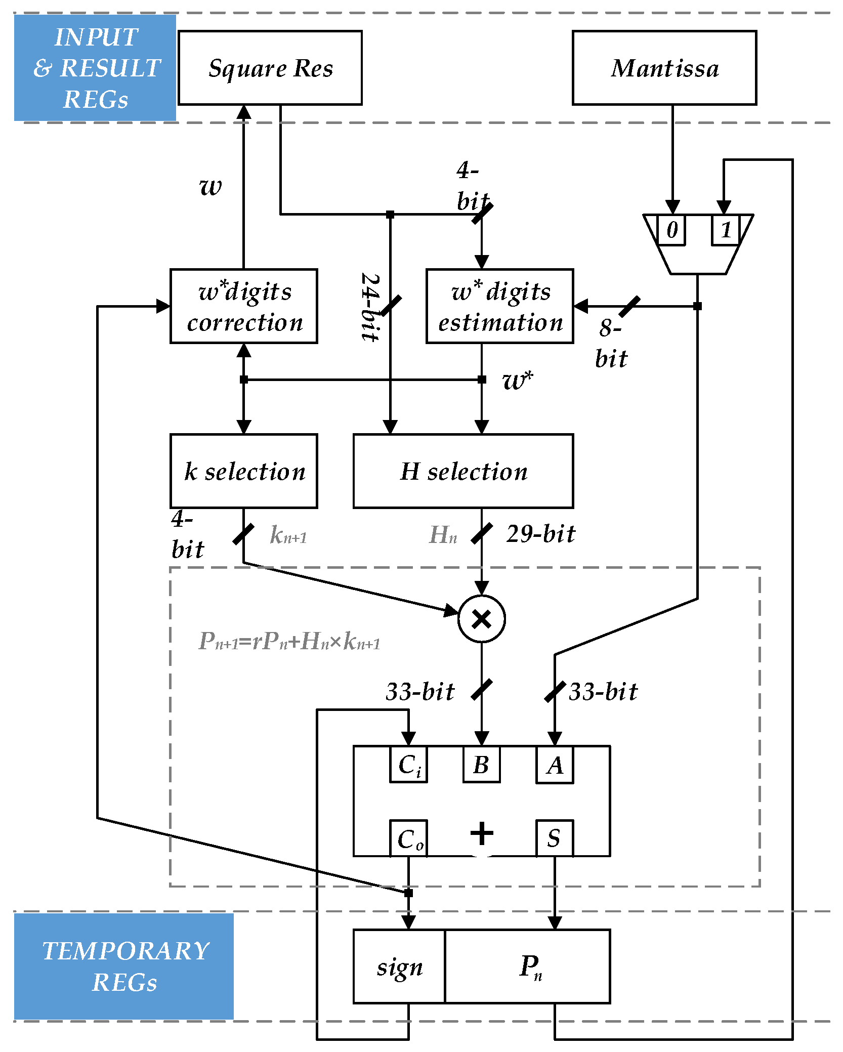
According to Equations (17)–(19), a single-precision floating-point square-root circuit with radix-16 is designed. The structure of mantissa iteration is shown in
Figure 1. The structure is similar to the square-root circuit base on standard SRT algorithm. In
Figure 1, a partial square-root digits estimation circuit is used to replace the lookup table in the standard SRT algorithm. The partial square-root digits correction circuit and the
,
correction circuit corresponding to (17) and (18) are added. The necessary adders and multipliers in the standard SRT algorithm are also included.
The mantissa iterative circuit shown in
Figure 1 can generate 4-bit partial square-root digits in each iteration cycle. In order to support the 4 rounding modes specified in IEEE-754 standard, it will takes 7 cycles to perform a single-precision square-root operation to obtain the complete mantissa, while the rounding operation requires an additional cycle to be calculated separately.
Combining (17) and taking into account the rounding mode specified in IEEE-754 standard, the one input of multiplier in
Figure 1 is 4-bit, while the other bit-width of the input needs 33 to ensure the correctness of the result, and the bit-width of the adder also needs 33 to complete the calculation result in the last iteration cycle.
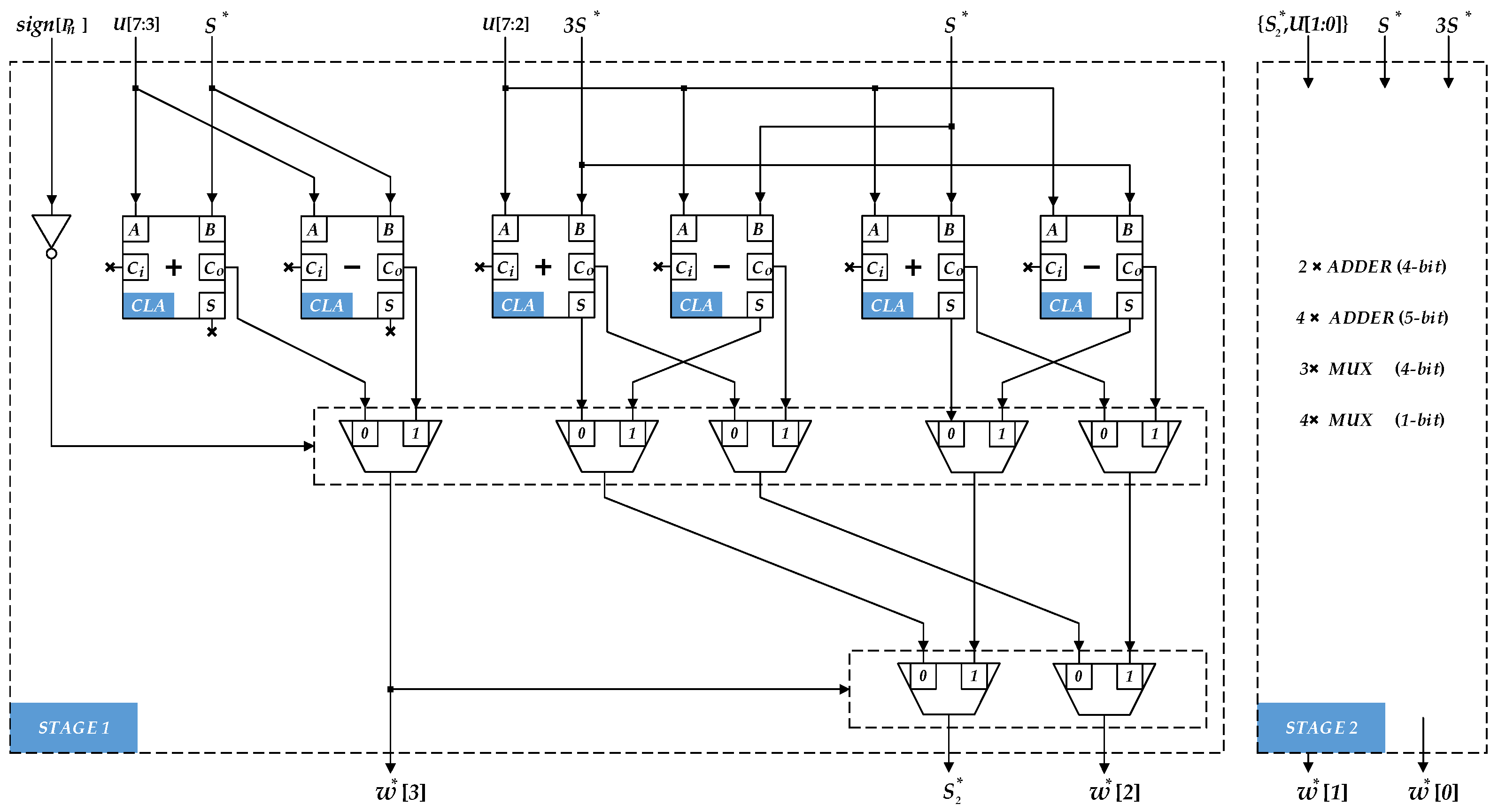
According to (13) and (14), the proposed partial square-root digits estimation circuit is shown in
Figure 2. Where
is the highest 8-bit of the partial remainder, and
is the highest 4-bit of the current square-root result. In each iteration cycle, the circuit can achieve 4-bit partial square-root digits.
It can be seen from (14): the estimation process of partial can be composed of 4-stage cascaded full-adders, but even if the carry look-ahead adder is used, it still needs 4-stage full-adder latency to get 4-bit partial square-root digits. In order to obtain a better timing performance, the structure of estimation circuit is improved in this paper. First, for the estimation process of each square-root digit in (14), the composite adder is used instead of the full-adder, so that the addition and subtraction are carried out independently, and the result of the addition/subtraction operation is selected according to the sign of the previous stage. The carry-in delay of full-adder is reduced. In addition, the secondary operation is expanded from (14) to (20):
It can be seen from (20) that by decomposing the secondary adder into two independent adders, the execution process of the secondary adder can be carried out simultaneously with the former adder. When the current stage adder obtains the final result, the next result will be obtained only after the latency of the one level 2-input multiplexer. Each cascade structure can reduce the latency of about one level adder, and the advantage of this circuit will be more obvious in higher radix structures.
Table 2 shows the latency and area cost evaluation results of partial square-root digits estimation circuits with different radices. The evaluation conditions are the worst process angle (voltage in 1.08 V, temperature in 125 °C) with 65 nm technology. From the data given in
Table 2, it can be seen that the critical path delay and area cost of the proposed partial square-root digits estimation circuit both almost increase linearly with the radix. Compared with the standard algorithm, the radix-256 partial square-root digits estimation circuit is only 1.8 K gates.
In order to achieve accurate results, it is necessary to detect and correct the error of the partial square-root digits and the partial remainder in iteration process. According to (15), the correction circuit of partial square-root digits can be realized by a subtracter with 4-bit. Based on (16), the coefficient correction circuit output estimated value or according to the sign of partial remainder in the previous iteration, and the result is still 4-bit.
According to (18), it can be seen that in the iterative process, the coefficient
can be realized by bit splicing, which is composed of
5-bit after left shift and 4-bit
. When
, the 5th digit of
is fixed to “0”, while when
, the 5th digit is fixed to “1”. The structure of the coefficient
correction circuit is shown in
Figure 3. Since the bit-width of the partial square-root digits is increased by 4 in each cycle, the splicing operation of the coefficient
needs to go through 7 cycles, adding a total of 3 levels latency of 2-input multiplexer. Since the correction operation of the coefficient
and
is carried out in parallel. The latency caused by the correction circuit is about the latency of 1 level 4-bit adder or 3 levels latency of 2-input multiplexer.
According to (18) and (19), the sign of the partial remainder is generated according to the previous iteration, and the partial remainder correction circuit will output
or
. Therefore, in the above two cases, the addition or subtraction operations need to be performed respectively. It means the independent adder and subtracter are implemented. As shown in
Figure 3, we use the characteristics of the full-adder to solve the above problem. When the addition operation is performed, the input operands of the adder is
, and the carry-in is 0. When the subtraction operation is performed, the input operands is
, where
is an inversion operation, which can be implemented by parallel XOR gates. The operation of the additional “1” to the complement code can be used as the carry-in of the full-adder. The structure in
Figure 3 can preform the partial remainder correction operation without increasing the adder resources, and the latency only increased by one level XOR gate.
5. Implement Results and Comparison
In order to get accurate evaluation results, we use Synopsys Design-Compiler to get the synthesis results of the proposed square-root circuit in 65 nm technology.
Table 3 shows the synthesis results under the worst process angle (1.08 V, 125 °C), clock frequency is 300 MHz.
The calculation period given in
Table 3 depends on the bit-width of the operand. In order to support the 4 rounding modes specified in IEEE-754 standard, sufficient square-root digits must be obtained in the iteration process. For the single-precision floating-point operand, at least 27 bits of square-root digits should be obtained, including 24 bits of standard square-root digits and 3 bits of rounding digits(guard bit, rounding bit and stick bit). Double-precision floating-point operand requires at least 56 bits of square-root digits, including 53 bits of standard square-root digits and 3 bits of rounding digits.
In addition, in order to provide a fair comparison with the results in other reports, the implementation results with different calculation precisions and different radices based on the proposed architecture are given in
Table 3. For the area cost of the square-root circuit,
Table 3 gives two expressions: the leaf cell count and the cell areas.
Combining the area cost of lookup table shown in
Table 1 with the area data shown in
Table 3, the advantages of the proposed design in area cost can be illustrated. When the radix is 64, only the lookup table (ROM) will cost 20,220.5 μm
2, while the overall area cost of the proposed square-root circuit is 9199.08 μm
2, which is only about 45% of the lookup table in the standard SRT algorithm. When the radix is 256, the area cost of the lookup table is 376,719.8 μm
2 while the area cost of the proposed square-root circuit is 12,017.88 μm
2, which is only about 3% of the lookup table circuit.
Through the comparison of the area data in
Table 1 and
Table 3, it can be seen that the huge area cost of the lookup table limits the application of the standard SRT algorithm in high radix square-root circuits. Therefore, in the design of high radix square-root circuit, the proposed architecture will have more obvious advantages in area cost. In addition, the bottleneck of high radix SRT square-root circuit is also solved.
Figure 4 shows the detailed function waveform of the square-root circuit with radix-16 and 32 bits based on the proposed architecture. The meanings of the signals are summarized as follows: “i_div_a” is the input data; “o_div_r” is the result output; ”o_div_hskd” is the valid indication signal of result; ”man_sub_o” is the estimated value of partial square-root digits, which corresponds to
in Equation (13); “man_qds_o” is the correction value of partial square-root digits, which corresponds to
in Equation (15); “rem_add_a” is the partial remainder generated in the previous iteration, which corresponds to
in Equation (19); “rem_add_o” is the partial remainder generated in current iteration, which corresponds to
in Equation (19); “rem_mul_o” corresponds to
in Equation (19) and “div_cnt_r” is a counter, which displays the calculation cycle and is used to control the iteration process.
In
Figure 4, the decimal floating point number input is 879,632.125, the hexadecimal representation is 0 × 4956_C102, the result of square-root value is 937.887, and the hexadecimal floating point number is 0 × 446A_78C5. As can be seen in
Figure 4, after 8 cycles of iterative calculation, the proposed square-root circuit can obtain correct results.
Moreover, when the partial remainder generated in current iteration cycle is negative, it indicates that there is an error in the
, and
can be corrected in current cycle, and the errors of partial remainder can be corrected in the next iteration through the circuit corresponding to Equation (18). The correction positions of the partial remainder and square-root digits are marked in the waveform of
Figure 4.
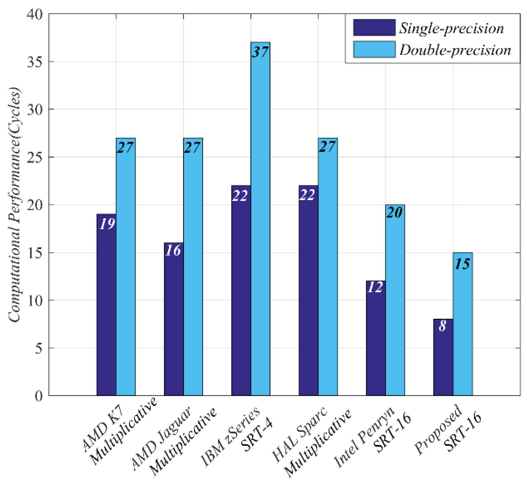
Figure 5 shows the comparison of the calculation cycle between the proposed square-root circuit and other mainstream processor. It must be pointed out that the comparison of calculation performance in
Figure 5 is only limited to the calculation cycles, without considering the technology, frequency, area cost, or power consumption in different processors.
As shown in
Figure 5, The performance of the square-root circuits based on multiplication operation is slightly higher than that of SRT-4 algorithm, and the performance of circuits is mainly limited by the latency of multiplication and accumulation units. Compared with SRT-4 algorithm, SRT-16 algorithm can get double bit-width of the square-root digits in each cycle, and the computational performance can be greatly improved. However, it can be seen from the algorithm implemented based on SRT in
Figure 5 that in the standard SRT algorithm, the area cost of lookup table of higher radix also limits the application in processor design. Even in Intel Penryn processor, the structure of SRT-4 cascade is used to implement SRT-16 algorithm.
Although the square-root circuit based on multiplication can improve the circuit performance, it increases the throughput of square-root unit to 1 cycle by the pipelined structure. However, the mainstream processors in
Figure 5 all adopt the iterative structure to reduce the penalty of pipeline clearing caused by missed branch prediction. It also shows that the proposed structure of square-root circuit is more suitable for the low-speed processor design based on RSIC-V instruction architecture set. In addition, in the comparison of computational performance in
Figure 5, the proposed structure proposed achieves lesser computational cycles.
Table 4 lists the comparison with other square-root circuits based on SRT algorithm, including the comparison of area cost (cell area and leaf cell count), operand precision, and power consumption. Considering the different technologies and frequencies used between different designs, in order to provide more fair comparison, the ratio of power consumption to frequency is provided as a reference for the comparison on power consumption.
Through the comparison of calculation performance in
Table 4, it can be seen that the area cost of this paper is reduced by 37.69% compared with [
15]. It should be noted that [
15] uses the 40-nm technology with smaller size, while this paper uses the 65-nm technology, if the shrinkage of technology size is considered, more area reduction will be achieved. In comparison with [
13], the number of equivalent gates is reduced by 66.71%, even the area cost of the proposed circuit is only 6.27% of [
16]. Compared with reference [
17], the circuit area of this paper is smaller, but the calculation performance can be nearly doubled.
Even if the same circuit is implemented in different technology, the power consumption is obviously different. In
Table 4, the power consumption of [
13,
16] implemented in 90 nm technology is about nine times than [
14,
15]. However, even compared with [
14,
15], which are implemented in 40 nm technology, the proposed structure also achieves lower dynamic power under the same calculation cycles and precision. Therefore, the proposed square-root structure is also suitable for power sensitive processor design.
Latency in
Table 4 represents the time required for the square-root circuit to complete calculation. It can be seen from
Table 4 that the performance of the square-root circuit based on the proposed algorithm is only higher than [
17] in terms of the maximum frequency and latency of the circuit. However, it should be pointed out that different process parameters (e.g., technology size, voltage, temperature, etc.,) have a significant impact on the maximum frequency of the circuit.
In order to avoid the impact of different process parameters, the combinational logic depth of the critical path in the circuit is generally used to evaluate the performance of the circuit. In
Table 4, the maximum logic depth of the square-root circuit with radix-16 and precisions of 32 and 64 are 33 and 41 levels, respectively. However, the data of the maximum logic depth is not given in other references. Therefore, the maximum frequency or performance cannot be directly compared across technology.
However, the maximum frequency and performance of the circuit can be indirectly compared according to the implementation structure of the algorithm. For the square-root circuits given in
Table 4, the performance of the circuit is determined by two parameters: the maximum frequency and the calculation cycle. According to the principle of SRT algorithm, the higher the radix r, the lesser number of the iteration cycles required to complete the calculation, and the square-root circuit can achieve higher performance under the same frequency. Both [
16,
17] adopt the standard SRT algorithm and the lookup table structure. However, from the area comparison data, it can be seen that compared with [
17], the radix of [
16] is increased by four times, the circuit area cost is increased by 17 times, and the calculation performance is improved by only two cycles. Neither [
14] nor [
15] adopts the lookup table structure. Instead, the cascade structure of lower radix SRT square-root circuit is adopted to obtain a higher radix. Although the significant increase of circuit area is avoided, when the radix is doubled, the critical path delay of the corresponding circuit will also double.
According to the data in
Table 3, when the radix of the square-root circuit based on the proposed algorithm is increased from 16 to 64, the circuit area cost is only increased by about 1.4 times, and the critical path delay is only increased by 1.5 times. Even when the radix is 256, the circuit area increases by only 1.8 times, and the critical path delay increases by only 1.9 times. Therefore, it can be seen from the data in
Table 3 and
Table 4 that although there is a gap in frequency compared with other reports, the proposed square-root structure has better tradeoff between the area cost and frequency, and is more suitable for applications that are sensitive to power consumption and area cost.


