
Quadrature Demodulator-Assisted Estimation of Load Voltage and Resistance Based on Primary-Side Information of a Wireless Power Transfer Link


Abstract
:1. Introduction
2. Inductive WPT Link
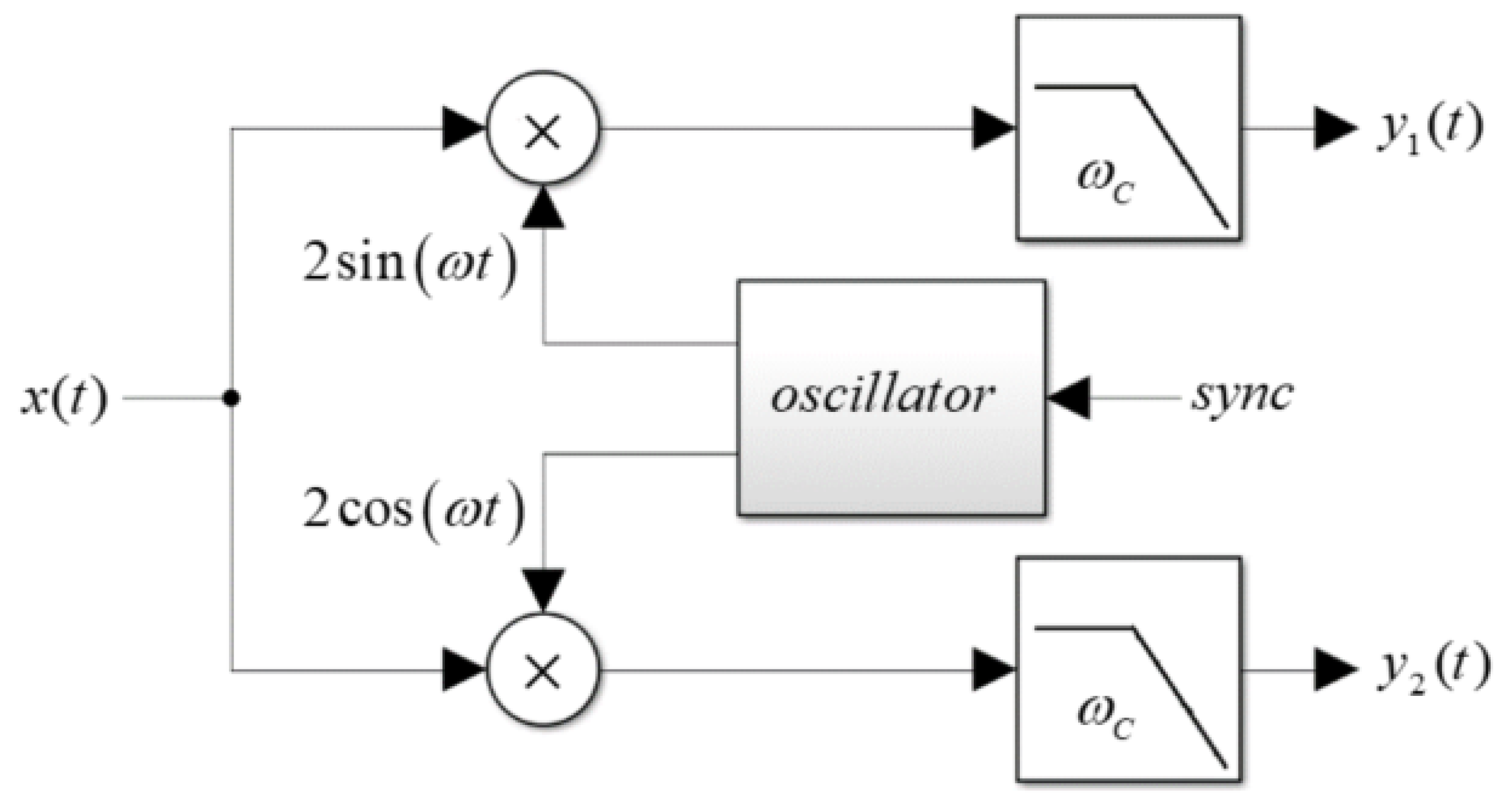
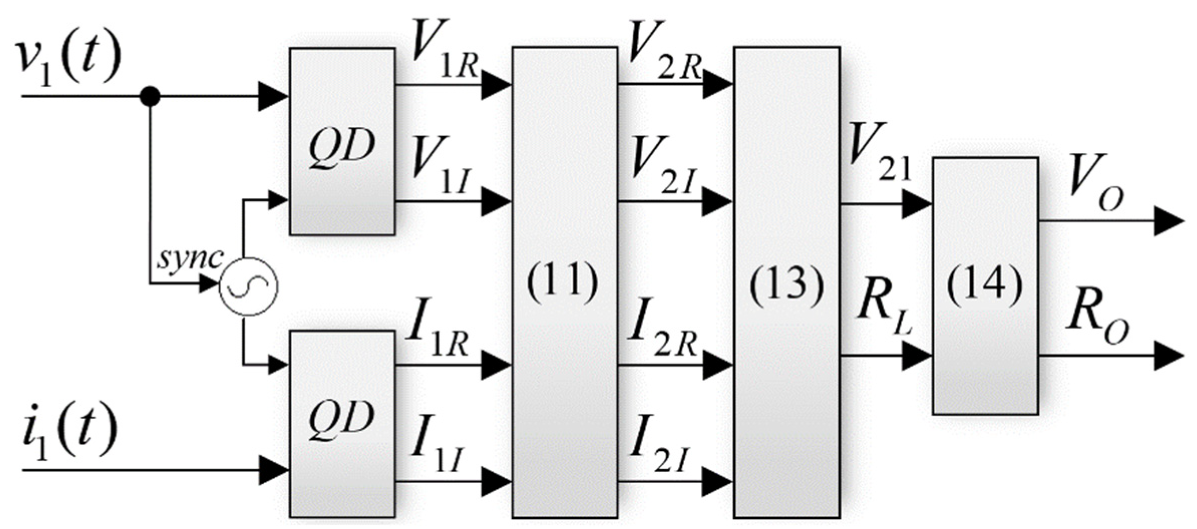
3. Quadrature Demodulation Essentials
4. Application to WPT Link Operating at Load-Independent-Voltage-Output Frequency
4.1. Attaining Load-Independent Voltage Output
4.2. Example
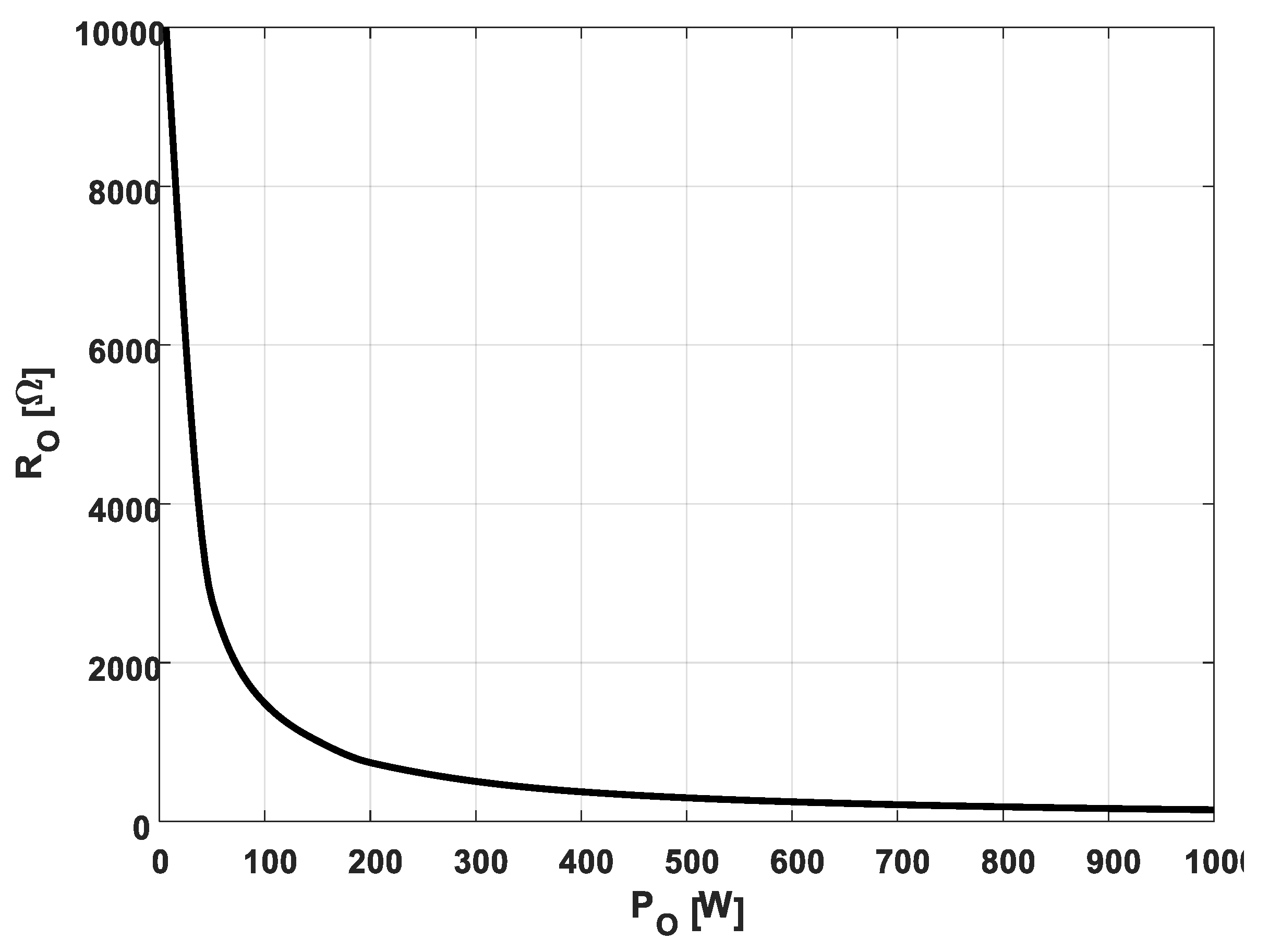
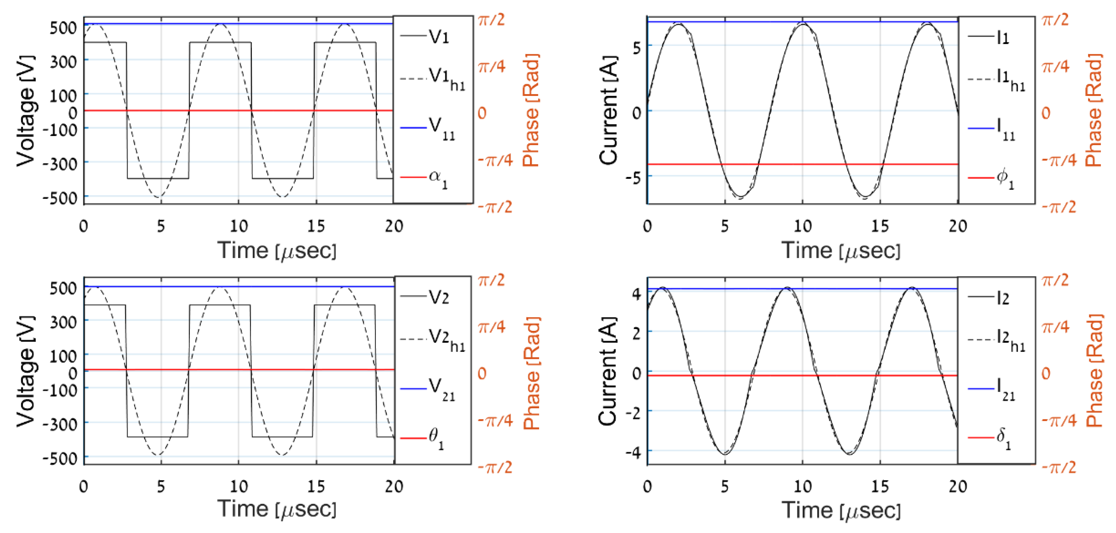
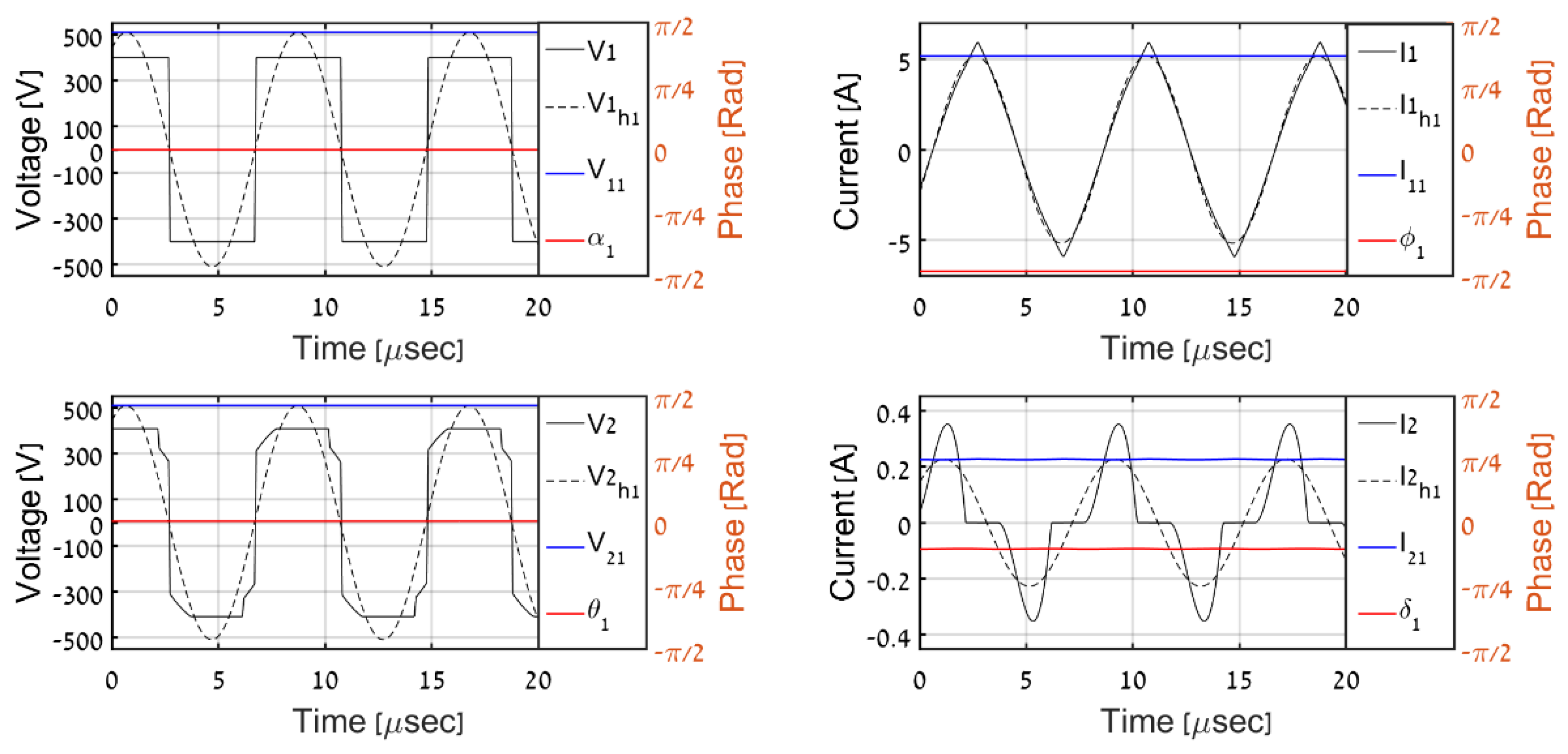
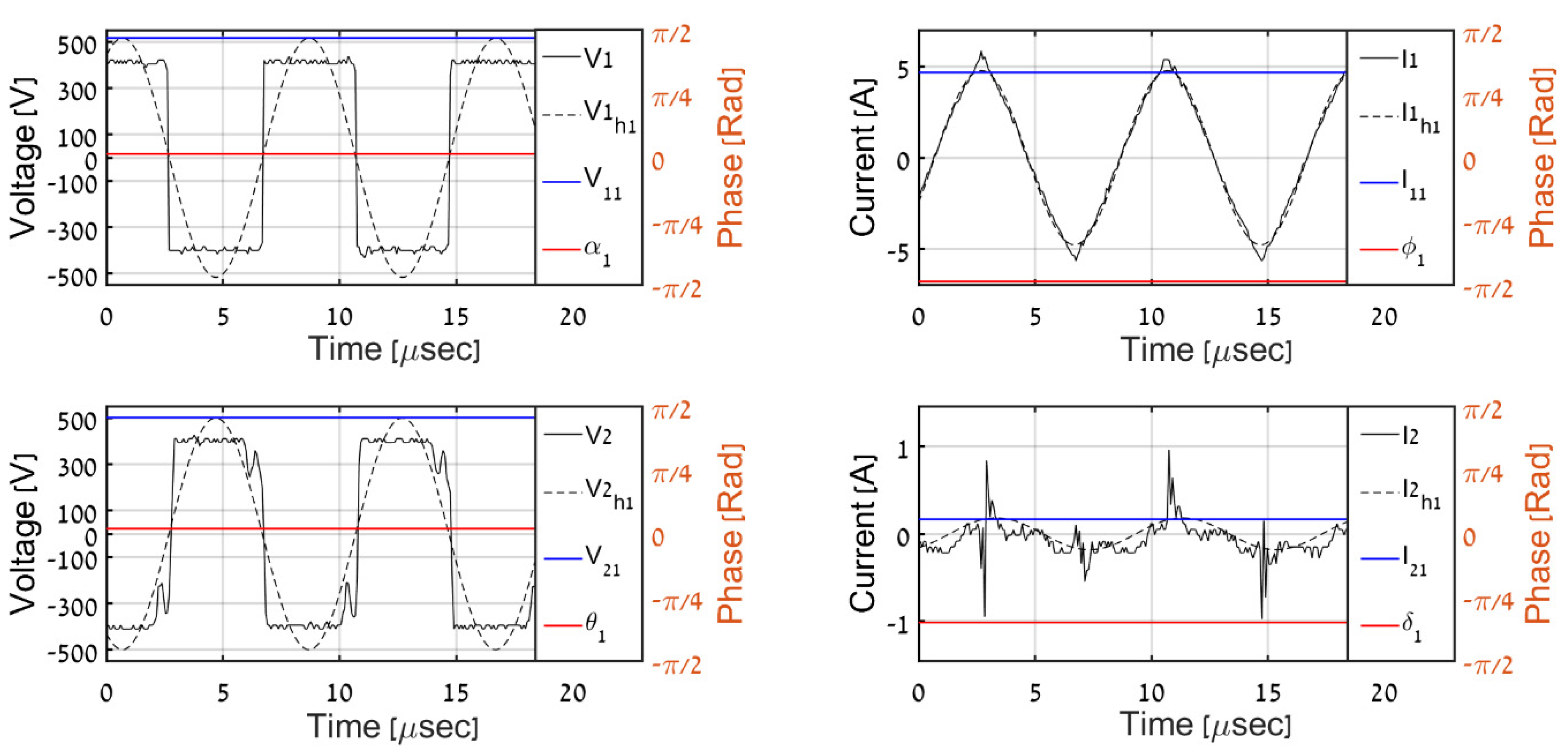
4.3. Simulations
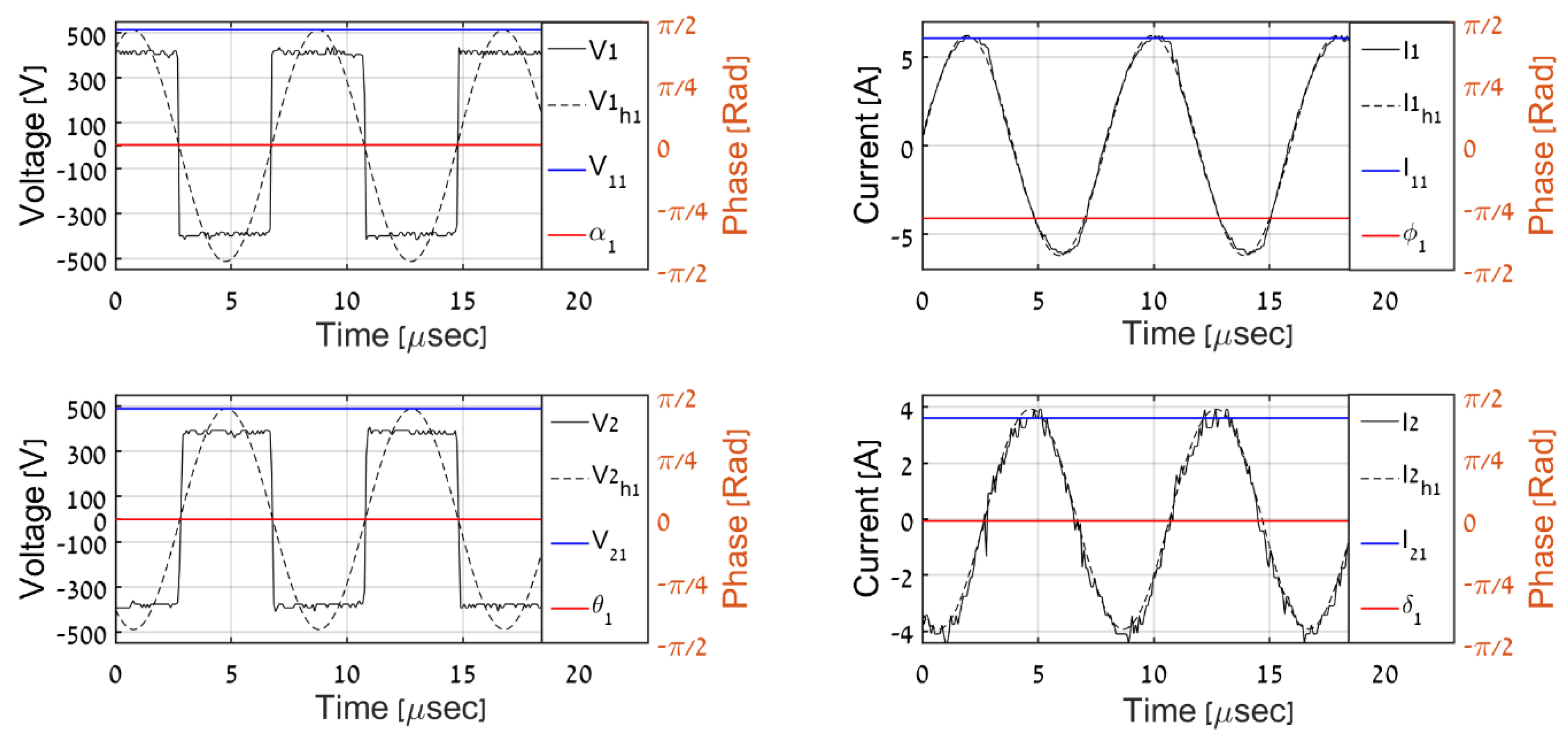
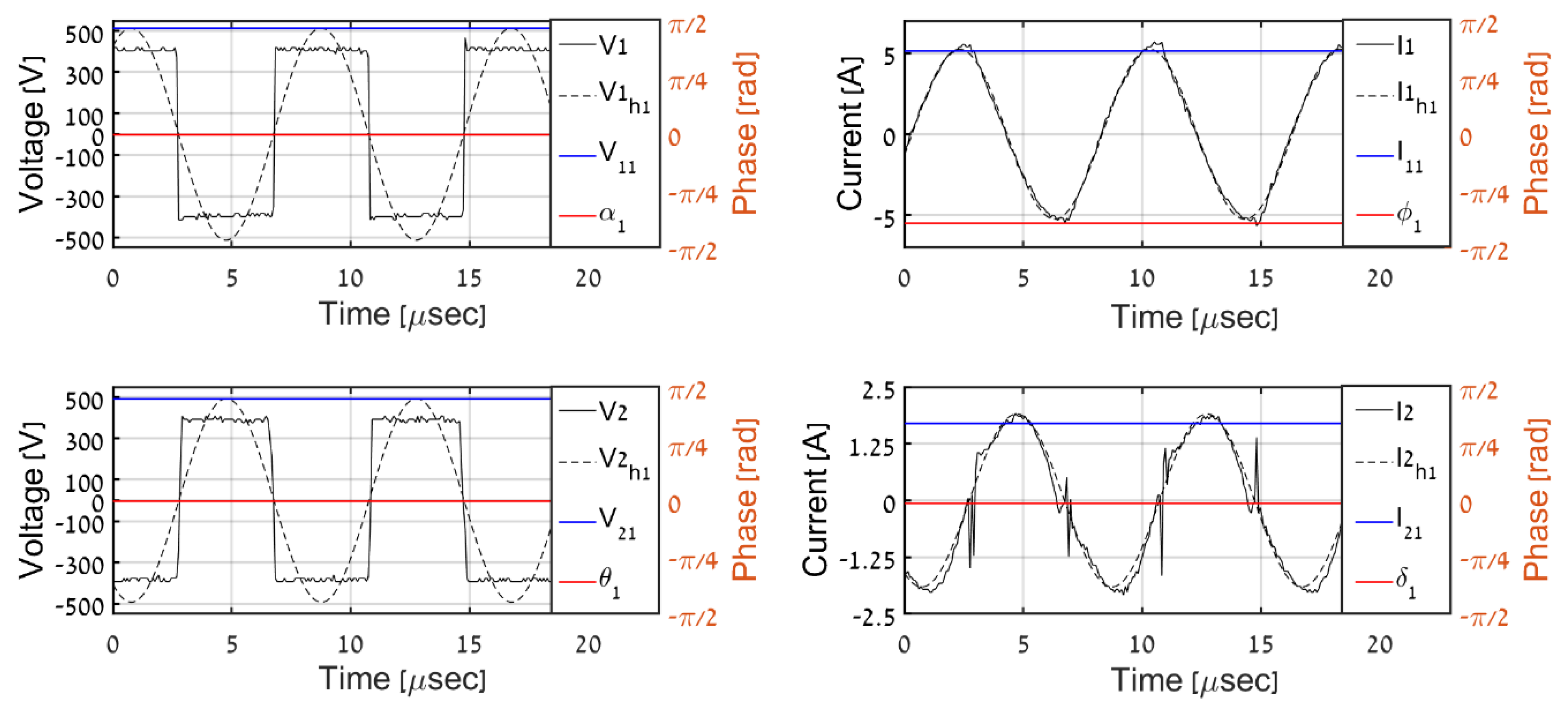
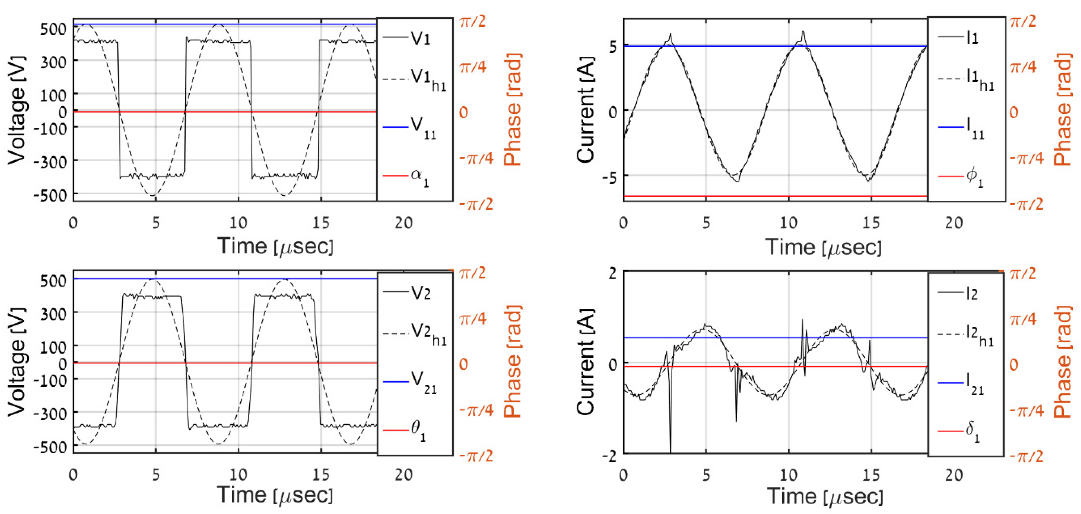
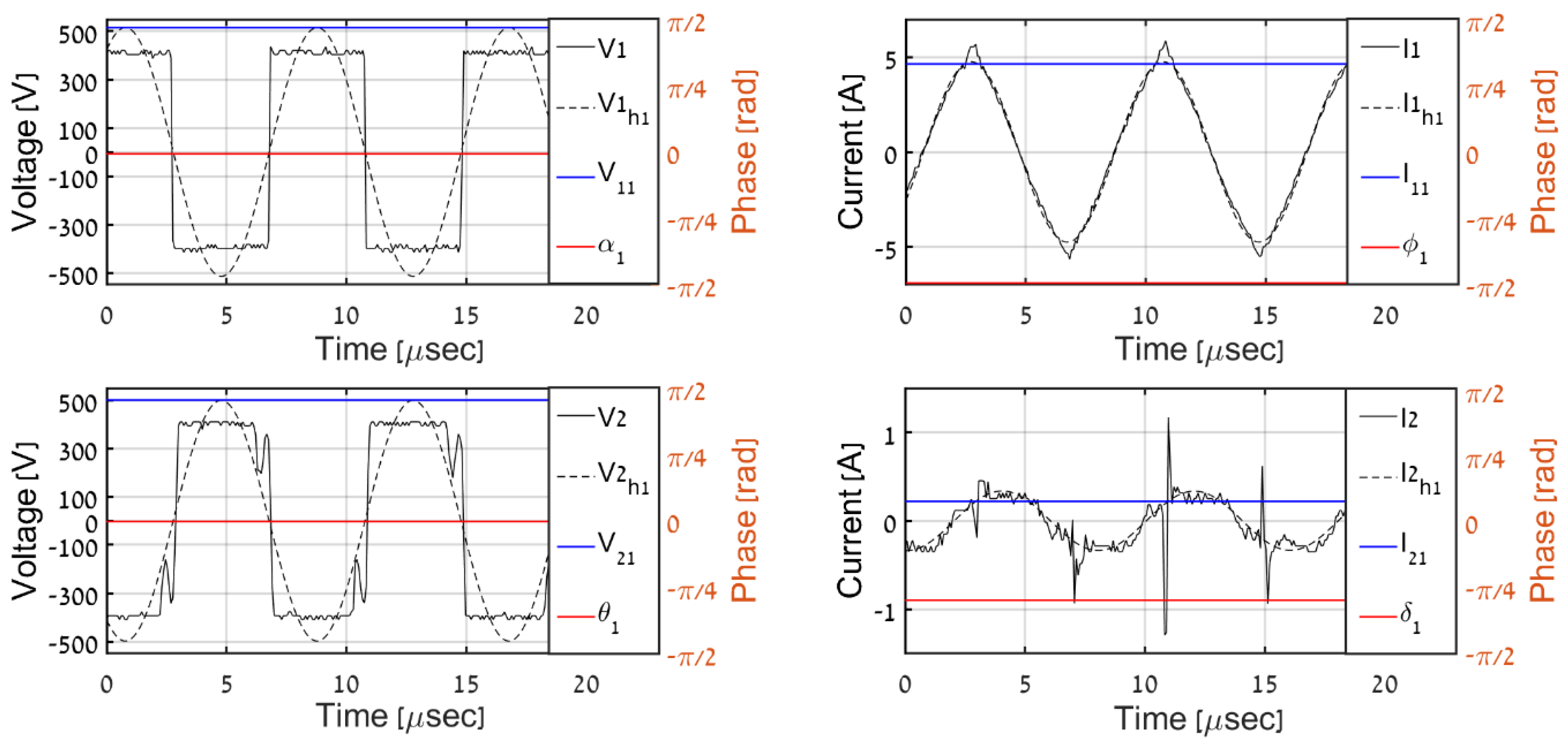
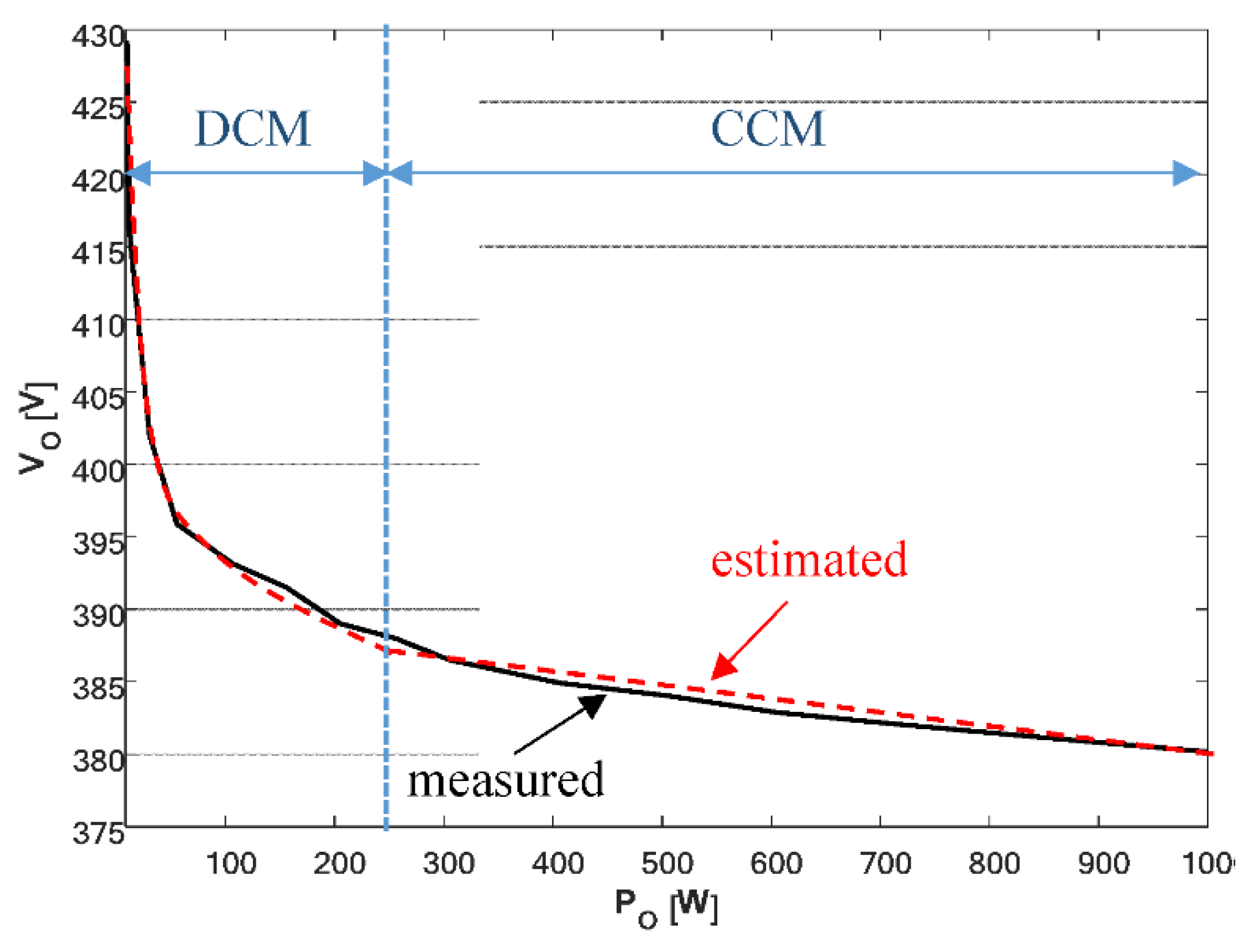
4.4. Experiments
5. Conclusions
Author Contributions
Funding
Conflicts of Interest
References
- Zhang, Z.; Pang, H.; Georgiadis, A.; Cecati, C. Wireless power transfer—An overview. IEEE Trans. Ind. Electron. 2018, 66, 1044–1058. [Google Scholar] [CrossRef]
- Mi, C.; Buja, G.; Choi, S.Y.; Rim, C.T. Modern Advances in Wireless Power Transfer Systems for Roadway Powered Electric Vehicles. IEEE Trans. Ind. Electron. 2016, 63, 6533–6545. [Google Scholar] [CrossRef]
- Seong, J.Y.; Lee, S. A study on precise positioning for an electric vehicle wireless power transfer system using a ferrite antenna. Electronics 2020, 9, 1289. [Google Scholar] [CrossRef]
- Chau, K.T. Electric Vehicle Machines and Drives–Design, Analysis and Application; Wiley-IEEE Press: Hoboken, NJ, USA, 2015. [Google Scholar]
- Wen, F.; Chu, X.; Li, Q.; Gu, W. Compensation Parameters Optimization of Wireless Power Transfer for Electric Vehicles. Electronics 2020, 9, 789. [Google Scholar] [CrossRef]
- Li, J.; Tan, L.; Huang, X.; Wang, R.; Zhang, M. The Influence of Substrate Size Changes on the Coil Resistance of the Wireless Power Transfer System. Electronics 2020, 9, 1025. [Google Scholar] [CrossRef]
- Vázquez, J.; Roncero-Sánchez, P.; Parreño Torres, A. Simulation model of a 2-kW IPT charger with phase-shift control: Vali-dation through the tuning of the coupling factor. Electronics 2018, 7, 255. [Google Scholar] [CrossRef] [Green Version]
- Hu, S.; Liang, Z.; Wang, Y.; Zhou, J.; He, X. Principle and application of the contactless load detection based on the amplitude decay rate in a transient process. IEEE Trans. Power Electron. 2017, 32, 8936–8944. [Google Scholar] [CrossRef]
- Meng, X.; Qiu, D.; Lin, M.; Tang, S.C.; Zhang, B. Output Voltage Identification Based on Transmitting Side Information for Implantable Wireless Power Transfer System. IEEE Access 2018, 7, 2938–2946. [Google Scholar] [CrossRef]
- Miller, J.M.; Onar, O.C.; Chinthavali, M. Primary-Side Power Flow Control of Wireless Power Transfer for Electric Vehicle Charging. IEEE J. Emerg. Sel. Top. Power Electron. 2015, 3, 147–162. [Google Scholar] [CrossRef]
- Liu, F.; Chen, K.; Zhao, Z.; Li, K.; Yuan, L. Transmitter-Side Control of Both the CC and CV Modes for the Wireless EV Charging System with the Weak Communication. IEEE J. Emerg. Sel. Top. Power Electron. 2017, 6, 955–965. [Google Scholar] [CrossRef]
- Zhong, W.; Hui, S.Y.R. Charging time control of wireless power transfer systems without using mutual coupling information and wireless communication system. IEEE Trans. Ind. Electron. 2017, 64, 228–235. [Google Scholar] [CrossRef]
- Li, S.; Hui, S.Y.R. Comparative Study on Front-End Parameter Identification Methods for Wireless Power Transfer without Wireless Communication Systems. In Proceedings of the 2018 International Power Electronics Conference (IPEC-Niigata 2018-ECCE Asia), Niigata, Japan, 20–24 May 2018; Volume 1, pp. 2552–2557. [Google Scholar]
- Wang, Z.-H.; Li, Y.-P.; Sun, Y.; Tang, C.-S.; Lv, X. Load Detection Model of Voltage-Fed Inductive Power Transfer System. IEEE Trans. Power Electron. 2013, 28, 5233–5243. [Google Scholar] [CrossRef]
- Chow, J.P.-W.; Chung, H.S.-H.; Cheng, C.S. Use of Transmitter-Side Electrical Information to Estimate Mutual Inductance and Regulate Receiver-Side Power in Wireless Inductive Link. IEEE Trans. Power Electron. 2016, 31, 6079–6091. [Google Scholar] [CrossRef]
- Mohammad, M.; Choi, S. Sensorless estimation of coupling coefficient based on current and voltage harmonics analysis for wireless charging system. 2017 IEEE Energy Convers. Congr. Expo. ECCE 2017, 1, 2767–2772. [Google Scholar] [CrossRef]
- Yin, J.; Lin, D.; Lee, C.K.; Parisini, T.; Hui, S.Y.R. Front-end monitoring of multiple loads in wireless power transfer systems without wireless communication systems. IEEE Trans. Power Electron. 2015, 31, 2510–2517. [Google Scholar] [CrossRef] [Green Version]
- Yue, K.; Liu, Y.; Zhao, P.; Xue, B.; He, R. Time Domain Coupling Coefficient Estimation Using Transmitter-side Information in Wireless Power Transfer System. In Proceedings of the IECON 2019—45th Annual Conference of the IEEE Industrial Electronics Society, Lisbon, Portugal, 14–17 October 2019; Volume 1, pp. 4189–4194. [Google Scholar]
- Madawala, U.; Thrimawithana, D. New technique for inductive power transfer using a single controller. IET Power Electron. 2012, 5, 248. [Google Scholar] [CrossRef]
- Sun, L.; Sun, M.; Ma, D.; Tang, H. Detecting Load Resistance and Mutual Inductance in Series-Parallel Compensated Wireless Power Transfer System Based on Input-Side Measurement. Int. J. Antennas Propag. 2018, 2018, 2094637. [Google Scholar] [CrossRef]
- Yin, J.; Lin, D.; Lee, C.-K.; Hui, S.Y.R. A Systematic Approach for Load Monitoring and Power Control in Wireless Power Transfer Systems Without Any Direct Output Measurement. IEEE Trans. Power Electron. 2015, 30, 1657–1667. [Google Scholar] [CrossRef]
- Song, K.; Li, Z.; Jiang, J.; Zhu, C. Constant current/voltage charging operation for series–series and series–parallel compensated wireless power transfer systems employing primary-side controller. IEEE Trans. Power Electron. 2018, 33, 8065–8080. [Google Scholar] [CrossRef]
- Su, Y.-G.; Chen, L.; Wu, X.-Y.; Hu, A.P.; Tang, C.-S.; Dai, X.; Hu, P. Load and Mutual Inductance Identification from the Primary Side of Inductive Power Transfer System With Parallel-Tuned Secondary Power Pickup. IEEE Trans. Power Electron. 2018, 33, 9952–9962. [Google Scholar] [CrossRef]
- Yi, K. Output Voltage Analysis of inductive wireless power transfer with Series LC and LLC resonance operations depending on coupling condition. Electronics 2020, 9, 592. [Google Scholar] [CrossRef] [Green Version]
- Zhang, X.; Kan, T.; You, C.; Mi, C. Modeling and analysis of AC output power factor for wireless chargers in electric vehicles. IEEE Trans. Power Electron. 2017, 32, 1481–1492. [Google Scholar] [CrossRef]
- Zhang, Y.; Yan, Z.; Kan, T.; Liu, Y.; Mi, C.C. Modelling and analysis of the distortion of strongly-coupled wireless power transfer systems with SS and LCC–LCC compensations. IET Power Electron. 2019, 12, 1321–1328. [Google Scholar] [CrossRef] [Green Version]
- Trachtenberg, O.; Shoihet, A.; Beer, E.; Fux, E.; Tiktin, N.; Kolesnik, S.; Kuperman, A. Quadrature Demodulator based Output Voltage and Load Estimation of a Resonant Inductive WPT Link. In Proceedings of the 2019 IEEE PELS Workshop on Emerging Technologies: Wireless Power Transfer (WoW), London, UK, 18–21 June 2019; pp. 81–84. [Google Scholar]
- Costanzo, A.; Dionigi, M.; Mastri, F.; Mongiardo, M.; Monti, G.; Russer, J.A.; Russer, P.; Tarricone, L. Conditions for a load-independent operating regime in resonant inductive WPT. IEEE Trans. Microw. Theory Tech. 2017, 65, 1066–1076. [Google Scholar] [CrossRef]
- Trachtenberg, O.; Baimel, D.; Kuperman, A. Accurate first-harmonic-approximation-based model of the diode rectifier in series-series compensated inductive wireless power transfer link at load-independent-voltage-output frequency. AEU-Int. J. Electron. Commun. 2021, 135, 153732. [Google Scholar] [CrossRef]
- Zhang, W.; Wong, S.; Tse, C.K.; Chen, Q. Analysis and comparison of secondary series-and parallel-compensated inductive power transfer systems operating for optimal efficiency and load-independent voltage-transfer ratio. IEEE Trans. Power Electron. 2014, 29, 2979–2990. [Google Scholar] [CrossRef]
- Zhang, W.; Wong, S.C.; Tse, C.; Chen, Q. Design for Efficiency Optimization and Voltage Controllability of Series–Series Compensated Inductive Power Transfer Systems. IEEE Trans. Power Electron. 2014, 29, 191–200. [Google Scholar] [CrossRef]
- Wang, C.-S.; Covic, G.A.; Stielau, O.H. Power Transfer Capability and Bifurcation Phenomena of Loosely Coupled Inductive Power Transfer Systems. IEEE Trans. Ind. Electron. 2004, 51, 148–157. [Google Scholar] [CrossRef]
- Guo, Y.; Wang, L.; Zhang, Y.; Li, S.; Liao, C. Rectifier Load Analysis for Electric Vehicle Wireless Charging System. IEEE Trans. Ind. Electron. 2018, 65, 6970–6982. [Google Scholar] [CrossRef]
- Frechter, Y.; Kuperman, A. Output Voltage Range of a Power-Loaded Series–Series Compensated Inductive Wireless Power Transfer Link Operating in Load-Independent Regime. IEEE Trans. Power Electron. 2020, 35, 6586–6593. [Google Scholar] [CrossRef]
- Frechter, Y.; Kuperman, A. Analysis and design of inductive wireless power transfer link for feedback-less power delivery to enclosed compartment. Appl. Energy 2020, 278, 115743. [Google Scholar] [CrossRef]
- Frechter, Y.B.; Kuperman, A. On the Minimal Loading of Sensorless Series-Series Compensated Inductive WPT Link Operating at Load Independent Voltage Output Frequency without Feedback. IEEE Access 2020, 8, 192517–192526. [Google Scholar] [CrossRef]
- Available online: https://www.transphormusa.com/en/evaluation-kit/tdinv1000p100-kit/ (accessed on 18 November 2019).


| Parameter | Value | Units |
|---|---|---|
| VI | 400 | V |
| L1, L2 | 180 | µH |
| k | 0.71 | -- |
| r1, r2 | 1.9 | Ω |
| C1, C2 | 31.3 | nF |
| CO | 660 | µF |
| Power | ||||
|---|---|---|---|---|
| 1000 | 388 | 387.79 | 150.5 | 151.5 |
| 500 | 394.3 | 394.07 | 310.9 | 299.6 |
| 200 | 398.7 | 399.8 | 794.8 | 815 |
| 100 | 402.3 | 401 | 1618.4 | 1620 |
| 50 | 405.2 | 405.6 | 3283.7 | 3272 |
| Power | ||||
|---|---|---|---|---|
| 1000 | 380 | 379.2 | 147.4 | 150 |
| 500 | 384 | 384.7 | 294 | 305 |
| 200 | 389 | 389.6 | 786 | 815 |
| 100 | 393.1 | 393.6 | 1546 | 1475 |
| 50 | 395.9 | 399 | 3215 | 3210 |
Publisher’s Note: MDPI stays neutral with regard to jurisdictional claims in published maps and institutional affiliations. |
© 2021 by the authors. Licensee MDPI, Basel, Switzerland. This article is an open access article distributed under the terms and conditions of the Creative Commons Attribution (CC BY) license (https://creativecommons.org/licenses/by/4.0/).
Share and Cite
Trachtenberg, O.; Kuperman, A. Quadrature Demodulator-Assisted Estimation of Load Voltage and Resistance Based on Primary-Side Information of a Wireless Power Transfer Link. Electronics 2021, 10, 1858. https://doi.org/10.3390/electronics10151858
Trachtenberg O, Kuperman A. Quadrature Demodulator-Assisted Estimation of Load Voltage and Resistance Based on Primary-Side Information of a Wireless Power Transfer Link. Electronics. 2021; 10(15):1858. https://doi.org/10.3390/electronics10151858
Chicago/Turabian StyleTrachtenberg, Or, and Alon Kuperman. 2021. "Quadrature Demodulator-Assisted Estimation of Load Voltage and Resistance Based on Primary-Side Information of a Wireless Power Transfer Link" Electronics 10, no. 15: 1858. https://doi.org/10.3390/electronics10151858
APA StyleTrachtenberg, O., & Kuperman, A. (2021). Quadrature Demodulator-Assisted Estimation of Load Voltage and Resistance Based on Primary-Side Information of a Wireless Power Transfer Link. Electronics, 10(15), 1858. https://doi.org/10.3390/electronics10151858