
SC-FDE Layer for Sensor Networks in Remote Areas Using NVIS Communications

 , , ,
, , ,  , ,
, ,  ,
, 
Abstract
1. Introduction
2. Background Study
2.1. HF Communications Evolution
2.2. NVIS
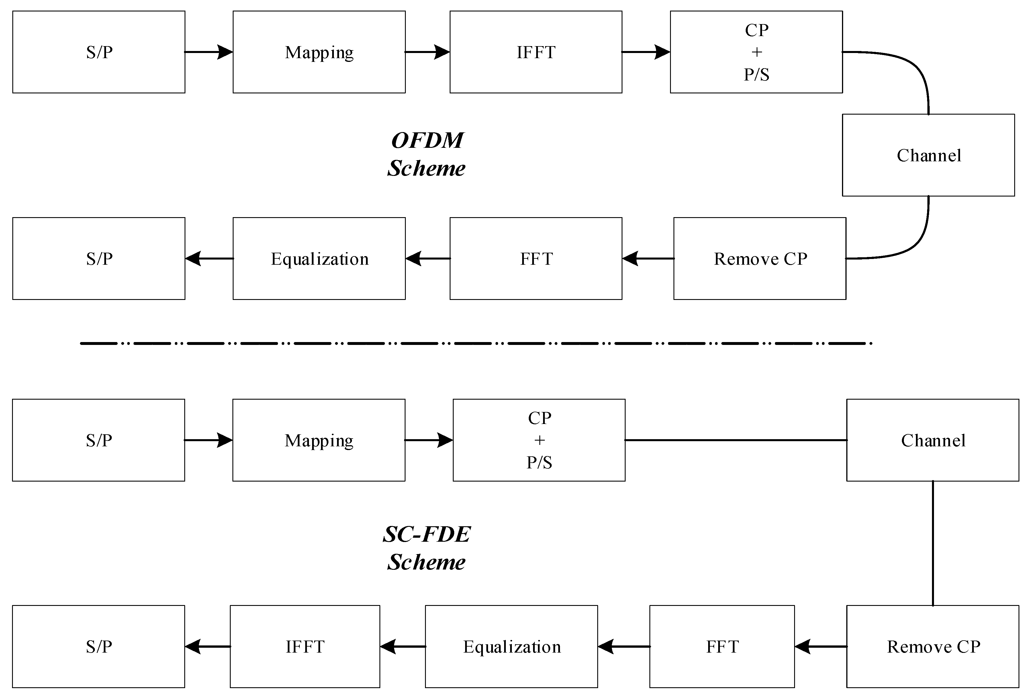
2.3. SC-FDE
3. Use Case
4. System Design
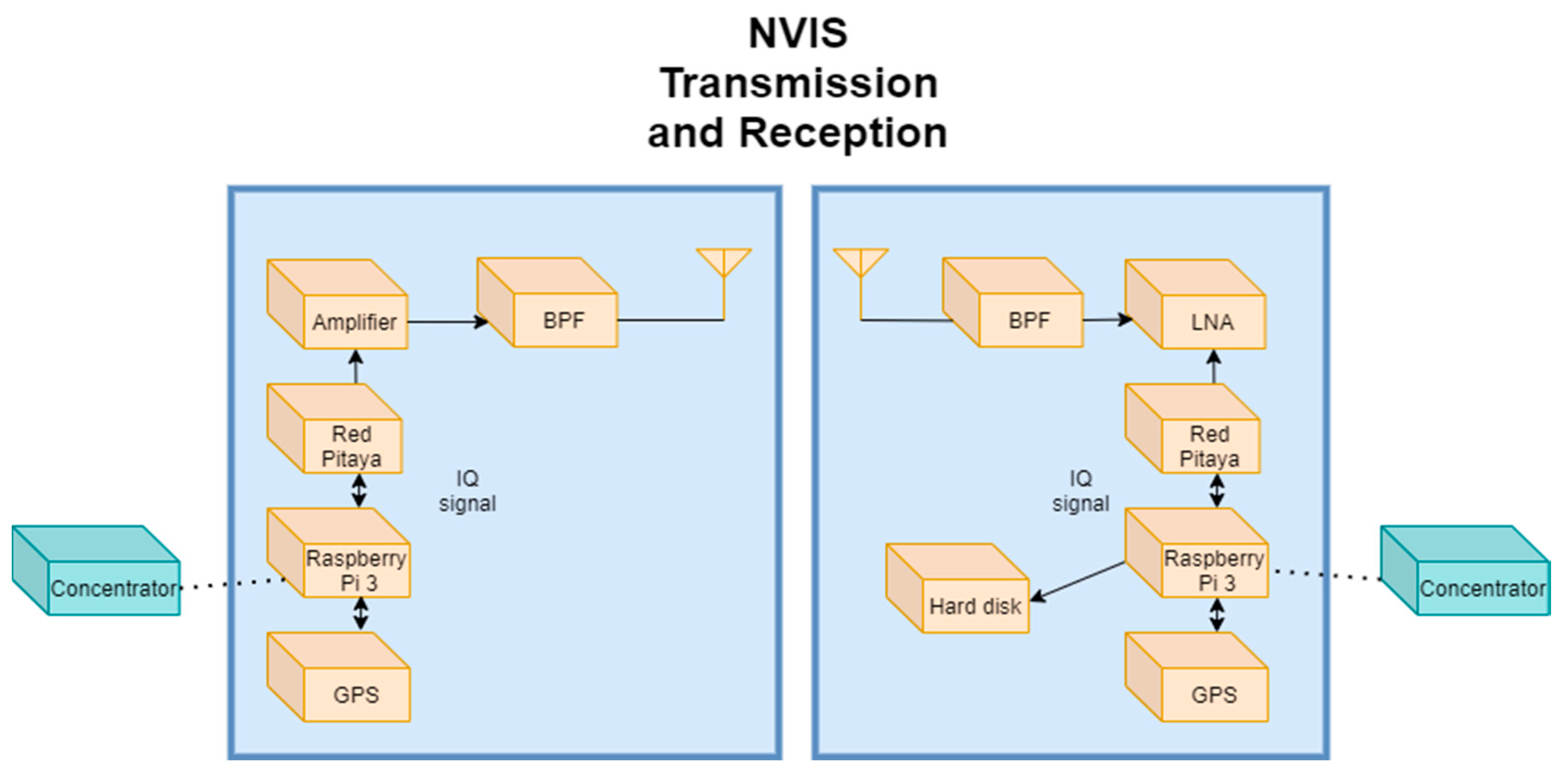
4.1. Platform Overview
4.2. Frame Design
5. Experimental Evaluation
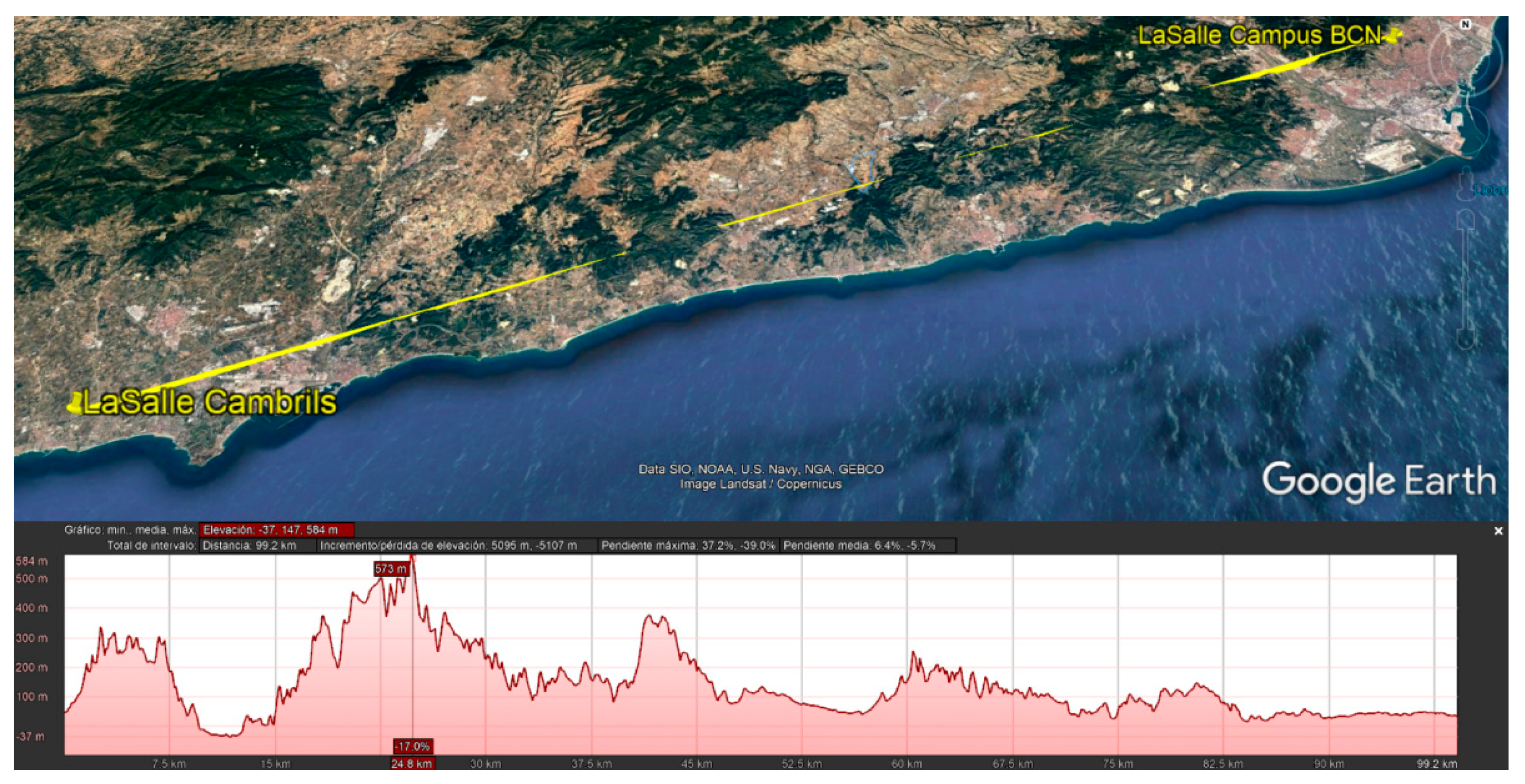
5.1. Test Area
5.2. Test Design
6. Results
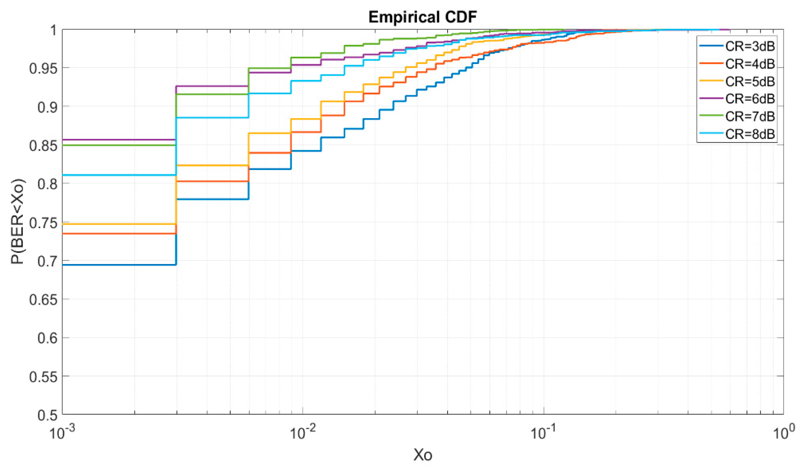
6.1. BER CDF
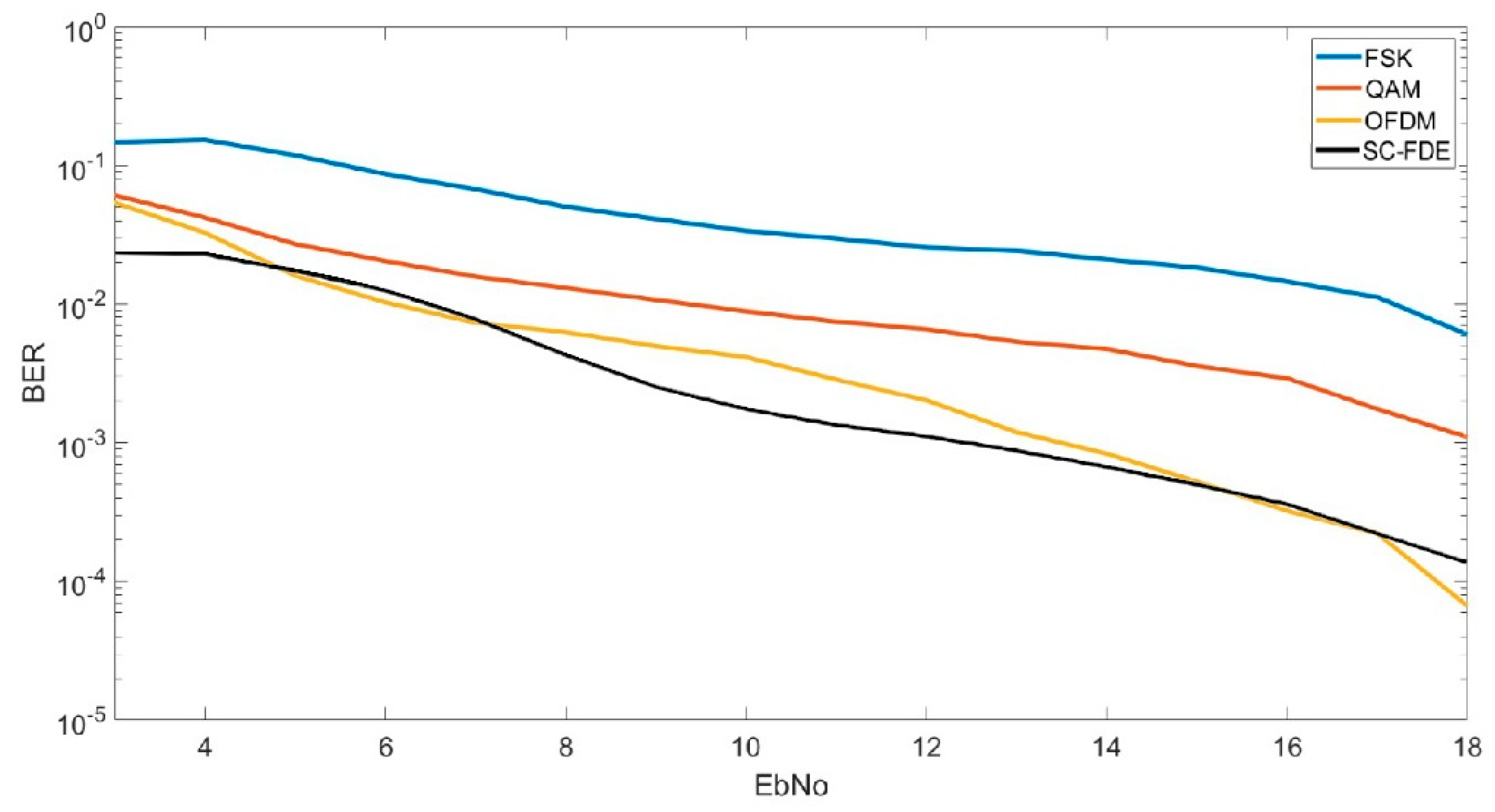
6.2. BER vs. Eb/No
6.3. CR Sweep
6.4. Sweep 12 W
6.5. Sweep 25 W
7. Conclusions
Author Contributions
Funding
Conflicts of Interest
Abbreviations
| ADC | Analog-Digital Converter |
| BER | Bit-error rate |
| BPF | A Band Pass Filter |
| CDF | Cumulative Distribution Function |
| CFR | Crest Factor Reduction |
| CP | Cyclic Prefix |
| CPU | Central Processing Unit |
| CR | Clipping Ratio |
| DAC | Digital-Analog Converter |
| DL | Downlink |
| Ds | Delay Spread |
| EVM | Error Vector Magnitude |
| FFT | Fast Fourier Transform |
| FPGA | Field-programmable gate array |
| HF | High Frequency |
| IBI | Inter-Block Interference |
| ICI | Inter-Carrier Interference |
| IFFT | Inverse Fast Fourier Transform |
| IoT | Internet of Things |
| ISI | Inter-symbol Interference |
| LNA | Low Noise Amplifier |
| LOS | Line of Sight |
| LSTM | Long Short-Term Memory |
| LTE | Long-Term Evolution |
| MER | Modulation Error Rate |
| MIMO | Multiple Input Multiple Output |
| ML | Maximum Likelihood |
| MMSE | Minimum Mean Square Equalizer |
| MUF | Maximum Usable Frequency |
| NVIS | Near Vertical Incidence Skywave |
| OFDM | Orthogonal Frequency Division Multiplexing |
| OFDMA | Orthogonal Frequency-Division Multiple Access |
| PAPR | Peak-to-average Power Ratio |
| PN | Pseudorandom Noise |
| PSK | Phase-shift keying |
| QAM | Quadrature Amplitude Modulation |
| SC-FDE | Single-Carrier Frequency-domain Equalization |
| SC-FDMA | Single-Carrier Frequency Division Multiple Access |
| SDR | Software Defined Radio |
| SIMO | Single Input Multiple Output |
| SNR | Signal-to-noise ratio |
| UL | Uplink |
| USN | Ubiquitous Sensor Networks |
| USN | Ubiquitous Sensor Network |
| ZF | Zero Forcing |
References
- Bagula, A.; Zennaro, M.; Inggs, G.; Scott, S.; Gascon, D. Ubiquitous sensor networking for development (USN4D): An application to pollution monitoring. Sensors 2012, 12, 391–414. [Google Scholar] [CrossRef]
- Wang, J.; Lim, M.K.; Wang, C.; Tseng, M.L. The evolution of the Internet of Things (IoT) over the past 20 years. Comput. Ind. Eng. 2021, 155, 107174. [Google Scholar] [CrossRef]
- Gazis, V.; Gortz, M.; Huber, M.; Leonardi, A.; Mathioudakis, K.; Wiesmaier, A.; Zeiger, F.; Vasilomanolakis, E. A survey of technologies for the internet of things. In Proceedings of the IWCMC 2015—11th International Wireless Communications and Mobile Computing Conference, Dubrovnik, Croatia, 24–28 August 2015; Institute of Electrical and Electronics Engineers Inc.: Piscataway, NJ, USA, 2015; pp. 1090–1095. [Google Scholar] [CrossRef]
- Smallsat Launch Services Feel Pricing Pressure-SpaceNews. Available online: https://spacenews.com/smallsat-launch-services-feel-pricing-pressure/ (accessed on 20 May 2021).
- The Cost of Building and Launching a Satellite|Globalcom Satellite Phones. Available online: https://globalcomsatphone.com/costs/ (accessed on 20 May 2021).
- Porte, J.; Briones, A.; Maso, J.M.; Pares, C.; Zaballos, A.; Pijoan, J.L. Heterogeneous wireless IoT architecture for natural disaster monitorization. Eurasip J. Wirel. Commun. Netw. 2020, 2020, 184. [Google Scholar] [CrossRef]
- Witvliet, B.A.; van Maanen, E.; Petersen, G.J.; Westenberg, A.J.; Bentum, M.J.; Slump, C.H.; Schiphorst, R. Near Vertical Incidence Skywave Propagation: Elevation Angles and Optimum Antenna Height for Horizontal Dipole Antennas. IEEE Antennas Propag. Mag. 2015, 57, 129–146. [Google Scholar] [CrossRef]
- Porte, J.; Maso, J.; Pijoan, J.L.; Miret, M.; Badia, D.; Jayasinghe, J. Education and e-health for developing countries using NVIS communications. In Proceedings of the IEEE Region 10 Humanitarian Technology Conference, R10-HTC, Malambe, Sri Lanka, 6–8 December 2019; Institute of Electrical and Electronics Engineers Inc.: Piscataway, NJ, USA, 2019. [Google Scholar] [CrossRef]
- Porte, J.; Maso, J.; Pijoan, J.L.; Badia, D. Design, implementation, and test of an SDR for NVIS communications. Int. J. Circuit Theory Appl. 2019, 47, 1502–1512. [Google Scholar] [CrossRef]
- Daniels, R.C.; Peters, S.W. A new MIMO HF data link: Designing for high data rates and backwards compatibility. In Proceedings of the Proceedings-IEEE Military Communications Conference MILCOM, San Diego, CA, USA, 18–20 November 2013; pp. 1256–1261. [Google Scholar] [CrossRef]
- Daniels, R.C.; Peters, S.W.; Heath, R.W. HF MIMO NVIS measurements with co-located dipoles for future tactical communications. In Proceedings of the IEEE Military Communications Conference MILCOM, San Diego, CA, USA, 18–20 November 2013; pp. 1250–1255. [Google Scholar] [CrossRef]
- Kuschnerov, M.; Piyawanno, K.; De Man, E.; Chouayakh, M.; Spinnler, B.; Alfiad, M.; Napoli, A.; Lankl, B. Data-aided single-carrier coherent receivers. In Proceedings of the Conference Proceedings-Lasers and Electro-Optics Society Annual Meeting-LEOS, Belek-Antalya, Turkey, 4–8 October 2009; pp. 638–639. [Google Scholar] [CrossRef]
- Fazel, K.; Kaiser, S. Multi-Carrier and Spread Spectrum Systems: From OFDM and MC-CDMA to LTE and WiMAX|Wiley eBooks|IEEE Xplore. Available online: https://ieeexplore.ieee.org/book/8039579 (accessed on 29 April 2021).
- Narasimhamurthy, A.B.; Banavar, M.K.; Tepedelenliouglu, C. OFDM Systems for Wireless Communications. Synth. Lect. Algorithms Softw. Eng. 2010, 2, 1–78. [Google Scholar] [CrossRef]
- Navita, A.; Amandeep, N. Performance analysis of OFDMA, MIMO and SC-FDMA technology in 4G LTE networks. In Proceedings of the 2016 6th International Conference-Cloud System and Big Data Engineering, Confluence 2016, Noida, India, 14–15 January 2016; Institute of Electrical and Electronics Engineers Inc.: Piscataway, NJ, USA, 2016; pp. 554–558. [Google Scholar] [CrossRef]
- Choi, J. Single-Carrier Index Modulation for IoT Uplink. IEEE J. Sel. Top. Signal. Process. 2019, 13, 1237–1248. [Google Scholar] [CrossRef]
- Iraqi, Y.; Al-Dweik, A. Efficient Information Transmission Using Smart OFDM for IoT Applications. IEEE Internet Things J. 2020, 7, 8397–8409. [Google Scholar] [CrossRef]
- Hussein, A.; Elgala, H. Lightweight Multi-Carrier Modulation for IoT; Broadband Access Communication Technologies XII; International Society for Optics and Photonics: San Francisco, CA, USA, 2018; p. 105590W. [Google Scholar] [CrossRef]
- Hervás, M.; Alsina-Pagès, R.M.; Pijoan, J.L.; Salvador, M.; Badia, D. Advanced modulation schemes for an Antarctic Long Haul HF Link: Performance comparison between SC-FDE, OFDMA and SC-FDMA in a hostile environment. Telecommun. Syst. 2016, 62, 757–770. [Google Scholar] [CrossRef]
- Maso, J.M.; Gonzalez, T.; Male, J.; Porte, J.; Pijoan, J.L.; Badia, D. NVIS multicarrier modulations for remote-sensor applications. Sensors 2020, 20, 6232. [Google Scholar] [CrossRef] [PubMed]
- Boyuan, X.; Weizhang, X. Research of the SC-FDE synchronization technology in HF wireless communication. In Proceedings of the 2013 IEEE 8th Conference on Industrial Electronics and Applications, ICIEA 2013, Melbourne, Australia, 19–21 June 2013; pp. 1420–1423. [Google Scholar] [CrossRef]
- Wang, Z.; Pu, F.; Yang, X.; Chen, N.; Shuai, Y.; Yang, R. Online LSTM-Based Channel Estimation for HF MIMO SC-FDE System. IEEE Access 2020, 8, 131005–131020. [Google Scholar] [CrossRef]
- Duan, H.; Yu, X.; Hou, Y. Efficient channel parameters estimation design for SC-FDE in HF wireless communications. In Proceedings of the 2015 8th International Congress on Image and Signal Processing, CISP 2015, Shenyang, China, 14–16 October 2015; Institute of Electrical and Electronics Engineers Inc.: Piscataway, NJ, USA, 2015; pp. 1338–1342. [Google Scholar] [CrossRef]
- Myung, H.G. Introduction to Single Carrier FDMA-IEEE Conference Publication. Available online: https://ieeexplore.ieee.org/document/7099187 (accessed on 22 April 2021).
- Yoshizawa, S.; Tanimoto, H.; Saito, T. SC-FDE vs. OFDM: Performance comparison in shallow-sea underwater acoustic communication. In Proceedings of the 2016 International Symposium on Intelligent Signal Processing and Communication Systems, ISPACS 2016, Phuket, Thailand, 24–27 October 2016; Institute of Electrical and Electronics Engineers Inc.: Piscataway, NJ, USA, 2016. [Google Scholar] [CrossRef]
- Pancaldi, F.; Vitetta, G.M.; Kalbasi, R.; Al-Dhahir, N.; Uysal, M.; Mheidat, H. Single-Carrier Frequency Domain Equalization [A focus on wireless applications]. IEEE Signal Process. Mag. 2008. [Google Scholar] [CrossRef]
- Si, L.; Yu, X.; Yin, H.; Xu, W. Compressive sensing-based channel estimation for SC-FDE system. Eurasip J. Wirel. Commun. Netw. 2019, 2019, 16. [Google Scholar] [CrossRef]
- Wang, J.; Ding, G.; Wang, H. HF communications: Past, present, and future. China Commun. 2018, 15, 1–9. [Google Scholar] [CrossRef]
- Johnson, E.E. Third-Generation and Wideband HF Radio Communications; Artech House: Norwood, MA, USA, 2013. [Google Scholar]
- Austin, B.A. Near vertical incidence skywaves in World War II: An historical perspective. In Proceedings of the 8th International Conference on High-Frequency Radio Systems and Techniques, Guildford, UK, 10–13 July 2000; IET: Piscataway, NJ, USA, 2000; pp. 225–229. [Google Scholar] [CrossRef]
- Witvliet, B.A.; Alsina-Pagès, R.M. Radio communication via Near Vertical Incidence Skywave propagation: An overview. Telecommun. Syst. 2017, 66, 295–309. [Google Scholar] [CrossRef]
- Appleton, E.V.; Barnett, M.A.F. On some direct evidence for downward atmospheric reflection of electric rays. Proc. R. Soc. Lond. Ser. Contain. Pap. Math. Phys. Character 1925, 109, 621–641. [Google Scholar] [CrossRef]
- Appleton, E.V.; Builder, G. The ionosphere as a doubly-refracting medium. Proc. Phys. Soc. 1933, 45, 208–220. [Google Scholar] [CrossRef]
- Witvliet, B.A. Near Vertical Incidence Skywave: Interaction of Antenna and Propagation Mechanism. Available online: https://www.researchgate.net/publication/284284255_Near_Vertical_Incidence_Skywave_-_Interaction_of_Antenna_and_Propagation_Mechanism_PhD_Thesis (accessed on 20 May 2021).
- Gomes, R.; Al-Daher, Z.; Hammoudeh, A.; Sobaihi, K.; Caldeirinha, R.; Fernandes, T. Performance and evaluation of OFDM and SC-FDE over an AWGN propagation channel under RF impairments using simulink at 60 GHz. In Proceedings of the 2014 Loughborough Antennas and Propagation Conference, LAPC 2014, Loughborough, UK, 10–11 November 2014; Institute of Electrical and Electronics Engineers Inc.: Piscataway, NJ, USA, 2014; pp. 685–689. [Google Scholar] [CrossRef]
- Male, J.; Porte, J.; Gonzalez, T.; Maso, J.M.; Pijoan, J.L.; Badia, D. Analysis of the Ordinary and Extraordinary Ionospheric Modes for NVIS Digital Communications Channels. Sensors 2021, 21, 2210. [Google Scholar] [CrossRef]
- De Figueiredo, F.A.P.; Mathilde, F.S.; Cardoso, F.A.C.M.; Vilela, R.M.; Miranda, J.P. Efficient frequency domain zadoff-chu generator with application to LTE and LTE-A systems. In Proceedings of the 2014 International Telecommunications Symposium, ITS 2014-Proceedings, Sao Paulo, Brazil, 17–20 August 2014; Institute of Electrical and Electronics Engineers Inc.: Piscataway, NJ, USA, 2014. [Google Scholar] [CrossRef]
- Trimeche, A.; Sakly, A.; Mtibaa, A. FPGA Implementation of ML, ZF and MMSE Equalizers for MIMO Systems. Procedia Comput. Sci. 2015, 73. [Google Scholar] [CrossRef][Green Version]
- Hervás, M.; Pijoan, J.L.; Alsina-Pagès, E.M.; Salvador, M.; Badia, D. Single-carrier frequency domain equalisation proposal for very long haul HF radio links. Electron. Lett. 2014, 50, 1252–1254. [Google Scholar] [CrossRef]
- Kim, W.J.; Cho, K.J.; Stapleton, S.P.; Kim, J.H. An efficient crest factor reduction technique for wideband applications. Analog Integr. Circuits Signal. Process. 2007, 51, 19–26. [Google Scholar] [CrossRef]
- Ojima, M.; Hattori, T. PAPR reduction method using clipping and peak-windowing in CI/OFDM system. In Proceedings of the IEEE Vehicular Technology Conference, Baltimore, MD, USA, 30 September–3 October 2007; pp. 1356–1360. [Google Scholar] [CrossRef]
- Crest Factor Reduction-RFmx SpecAn 19.1 Help-National Instruments. Available online: https://zone.ni.com/reference/en-XX/help/374264N-01/rfmxspecan/crest_factor_reduction/ (accessed on 19 April 2021).
- Watch, T. Ubiquitous Sensor Networks (USN) ITU-T Technology Watch Briefing Report Series, No. 4. 2008. Available online: http://www.itu.int/md/T05-NGN.GSI-DOC-0266/en (accessed on 18 May 2021).
- Yu, W.; Liang, F.; He, X.; Hatcher, W.G.; Lu, C.; Lin, J.; Yang, X. A Survey on the Edge Computing for the Internet of Things. IEEE Access 2017, 6, 6900–6919. [Google Scholar] [CrossRef]
- Red Pitaya-Stemlab Swiss Army Knife for Engineers. Available online: https://www.redpitaya.com/ (accessed on 20 May 2021).
- Raspberry Pi 3 Model B+–Raspberry Pi. Available online: https://www.raspberrypi.org/products/raspberry-pi-3-model-b-plus/ (accessed on 13 April 2021).
- Bonn, E. Bonn Elektronik BLWA 0103-250 1.5.30 MHZ. Available online: http://frontend.bonn-elektronik.com/pdfsheet.php?modellreihe=140&smid=354&lang=eng (accessed on 2 June 2021).
- Maso, J.M.; Porte, J.; Pijoan, J.L.; Badia, D. Study of NVIS channel for USN protocol definition in antarctica. Electronics 2020, 9, 1037. [Google Scholar] [CrossRef]
- Maso, J.M.; Male, J.; Porte, J.; Pijoan, J.L.; Badia, D. Ionospheric polarization techniques for robust NVIS remote sensing platforms. Appl. Sci. 2020, 10, 3730. [Google Scholar] [CrossRef]
- Maso, J.M.; Porte, J.; Pijoan, J.L.; Badia, D. Internet of Things Communications for Remote Sensors in Antarctica Using NVIS. 2019. Available online: https://www.researchgate.net/publication/335774336_Internet_of_things_communications_for_remote_sensors_in_Antarctica_using_NVIS (accessed on 20 April 2021).
- Porté, J.; Lluis Pijoan, J.; Masó, J.; Badia, D.; Zaballos, A.; Maria Alsina-Pagès, R. Advanced HF Communications for Remote Sensors in Antarctica. In Antarctica—A Key to Global Change; IntechOpen: London, UK, 2018. [Google Scholar]
- Nikoukar, A.; Raza, S.; Poole, A.; Gunes, M.; Dezfouli, B. Low-power wireless for the internet of things: Standards and applications. IEEE Access 2018, 6, 67893–67926. [Google Scholar] [CrossRef]


| Parameters | SC-FDE Values | OFDM Values |
|---|---|---|
| Bandwidth | 3 kHz | 3 kHz |
| Useful symbol length (TS) | 0.33 ms | 9.33 ms |
| Prefix cyclic length (TCP) | 3 ms | 3 ms |
| Number of subcarriers (NSC) | 28 | 28 |
| Number of symbols (Nsymbol) | 7 | 7 |
| Number of pilot/symbol | 1 | 1 |
| Number of data symbol | 6 | 6 |
| Packet duration | 87.64 ms | 86.31 ms |
| Bits in packet | 336 bits | 324 bits |
| Modulation | QPSK | QPSK |
| Equalization | MMSE | ZF |
| Bitrate of signal frame | 3.833 kbps | 3.753 kbps |
Publisher’s Note: MDPI stays neutral with regard to jurisdictional claims in published maps and institutional affiliations. |
© 2021 by the authors. Licensee MDPI, Basel, Switzerland. This article is an open access article distributed under the terms and conditions of the Creative Commons Attribution (CC BY) license (https://creativecommons.org/licenses/by/4.0/).
Share and Cite
Gonzalez, T.; Porte, J.; Male, J.; Navarro, J.; Maso, J.M.; Zaballos, A.; Pijoan, J.L.; Badia, D. SC-FDE Layer for Sensor Networks in Remote Areas Using NVIS Communications. Electronics 2021, 10, 1636. https://doi.org/10.3390/electronics10141636
Gonzalez T, Porte J, Male J, Navarro J, Maso JM, Zaballos A, Pijoan JL, Badia D. SC-FDE Layer for Sensor Networks in Remote Areas Using NVIS Communications. Electronics. 2021; 10(14):1636. https://doi.org/10.3390/electronics10141636
Chicago/Turabian StyleGonzalez, Tomas, Joaquim Porte, Jordi Male, Joan Navarro, Josep M. Maso, Agustín Zaballos, Joan L. Pijoan, and David Badia. 2021. "SC-FDE Layer for Sensor Networks in Remote Areas Using NVIS Communications" Electronics 10, no. 14: 1636. https://doi.org/10.3390/electronics10141636
APA StyleGonzalez, T., Porte, J., Male, J., Navarro, J., Maso, J. M., Zaballos, A., Pijoan, J. L., & Badia, D. (2021). SC-FDE Layer for Sensor Networks in Remote Areas Using NVIS Communications. Electronics, 10(14), 1636. https://doi.org/10.3390/electronics10141636