Abstract
The performance of vehicle active safety systems relies on accurate vehicle state information. Estimation of vehicle state based on onboard sensors has been popular in research due to technical and cost constraints. Although many experts and scholars have made a lot of research efforts for vehicle state estimation, studies that simultaneously consider the effects of noise uncertainty and model parameter perturbation have rarely been reported. In this paper, a comprehensive scheme using dual Extended H-infinity Kalman Filter (EH∞KF) is proposed to estimate vehicle speed, yaw rate, and sideslip angle. A three-degree-of-freedom vehicle dynamics model is first established. Based on the model, the first EH∞KF estimator is used to identify the mass of the vehicle. Simultaneously, the second EH∞KF estimator uses the result of the first estimator to predict the vehicle speed, yaw rate, and sideslip angle. Finally, simulation tests are carried out to demonstrate the effectiveness of the proposed method. The test results indicate that the proposed method has higher estimation accuracy than the extended Kalman filter.
1. Introduction
1.1. Motivation
Active safety systems have proven themselves to be one of the most effective means of reducing traffic accidents. Some typical active safety systems include antilock braking systems [1], yaw stability systems [2], collision avoidance systems [3], and so on. The prerequisite for these active safety systems to work accurately is the availability of accurate vehicle state information [4]. Existing onboard sensors are limited in the number of vehicle states they can measure. Some states that characterize vehicle stability, such as the sideslip angle, cannot be measured by onboard sensors. Although some special sensors can measure the sideslip angle, they are expensive and require additional installation in mass production cars, which greatly limits the application of this measurement method. To obtain some key state information of the vehicle more economically, many scholars have proposed various interesting estimation methods.
1.2. Literature Review and Limitations
In recent years, the studies of estimation methods based on nonlinear observer and Kalman filter (KF) have been widely reported. In the literature [5,6,7,8], the method based on a nonlinear observer is used to estimate the vehicle state and is proved to be effective under certain conditions. However, the estimation accuracy of the nonlinear observer is heavily dependent on the accuracy of the vehicle model parameters. In addition, Kalman filter-based estimation methods are widely used in vehicle positioning, navigation, and control due to their ability to efficiently handle measurement noise [9]. Its iterative process consists of three steps. Firstly, the statistical properties of the system noise and the observation noise are used to process the time update and the observation update of the random signal, then the unknown variables are estimated, and finally, the optimal estimate is achieved [10].
In general, the traditional KF is only suitable for linear systems. It requires that the observation equation is linear [11]. Thus, it is not suitable for the state estimation of complicated and nonlinear vehicle systems. On the other hand, the traditional KF requires that the model parameters and noise variances are precisely known [12]. Furthermore, the process noise and measurement noise are white noises and are uncorrelated with each other [13]. In many practical applications, system model parameters and/or noise variance often are uncertainties because of model perturbation, stochastic disturbance, and unmodeled dynamics [14]. These factors usually deteriorate the estimation accuracy of KF.
Therefore, extended Kalman filtering [15,16,17] is proposed to deal with these problems. Some studies have shown that EKF has better estimation accuracy compared to KF [18,19,20,21,22]. However, when statistical properties of noise are unknown, the estimation accuracy of EKF will decrease. Thus, some scholars proposed the adaptive extended Kalman filter (AEKF) [23,24]. When the system noise is unknown, the AEKF-based solution can obtain more accurate vehicle states. In addition, some researchers attempt to utilize the H-infinity filter to estimate the vehicle states with noise uncertainties. In [25], the H-infinity filter was used to weaken the effect of noise uncertainty on the estimation accuracy. In addition, state estimation considering parameter perturbation is an interesting research hotspot. The model parameters to be identified will vary according to the complexity of the vehicle dynamics model. For example, considering vehicle drive conditions, some driveline parameters need to be obtained. Montonen et al. [26,27] identified the mechanical driveline parameters of a hybrid bus by inputting a pseudo-random binary signal. Furthermore, some scholars have proposed a comprehensive estimation architecture [6,28,29]. It generally consists of two parts: one is the online estimation of the parameters of the model, and the other is the use of various filtering algorithms to obtain better estimation performance based on the updated model.
Although a lot of research work has been done by many experts and scholars for the above problems, few studies have been reported considering both noise uncertainty and model parameter perturbation. Thus, in the paper, we propose a novel comprehensive scheme for vehicle state estimation. The main contributions of this article are as follows. A comprehensive scheme using dual EH∞KF is proposed to estimate the vehicle mass and vehicle state when the noise statistics are unknown and model parameters are inaccurate. Furthermore, the virtual tests show that the proposed method can acquire higher estimation accuracy than the existing EKF. The remainder of this paper is structured as follows. The vehicle model is introduced in Section 2. Section 3 presents the proposed comprehensive scheme in detail. Section 4 shows the virtual test results. Finally, Section 5 concludes this work.
2. Vehicles Dynamics Estimation Models
Considering real-time computing requirements and estimator design issues, a nonlinear three-degree of freedom vehicle model (see Figure 1) is used for the vehicle state and parameter estimation [30]. In order to handle a tractable estimation problem using only the standard sensors, we have to make some assumptions. The steering angles of the front left and right wheels are the same. The left and right wheels on each axle have the same stiffness. The lateral forces are decoupled from the longitudinal forces. The effects of wind and air resistance are neglected. Its equations of motion are as follows:
where , are respectively yaw rate and sideslip angle; and are respectively longitudinal vehicle speed and lateral vehicle speed; and are respectively distance from the center of gravity to the front axle and distance from the center of gravity to the rear axle; is the wheelbase; and are respectively longitudinal and lateral forces on the front axle; and are respectively longitudinal and lateral forces on the rear axle; and are respectively cornering stiffness of the front axle and cornering stiffness of the rear axle; and are respectively vehicle moment of inertia about axis and vehicle mass; and are respectively longitudinal acceleration and lateral acceleration; and is front-wheel steering angle.
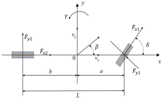
Figure 1.
The nonlinear three degrees of freedom vehicle model.
State and measurement equations of the vehicle model, that is, Formulations (1) and (2) can be converted to a continuous-time state-space model.
where , , and are respectively state vector, input vector, and measurement vector, for mass estimation: and ; for state estimation: , , and ; and are respectively the state process noise and measurement noise; and are respectively the state transition and output function.
It is necessary to discretize the continuous-time vehicle model to accomplish the estimation of vehicle states via discrete measurements. Equation (3) can be written as follows:
For mass estimation, , , is the sample time. The nonlinear vehicle system can be written as follows:
For state estimation, , . The nonlinear vehicle system can be written as follows:
3. Methodology
The framework of the proposed comprehensive scheme is presented in Figure 2, which consists of four modules: Input and output of vehicle signal; Vehicle model; Vehicle mass estimation based on EH∞KF; and Vehicle state estimation based on EH∞KF. The vehicle model receives the input signals including front wheel angle and lateral acceleration. Then, the sensors transmit the measurement signals with noise uncertainty and model parameter perturbation to the next estimators. The first EH∞KF estimator is used to identify the mass parameter of the vehicle. Meanwhile, the second EH∞KF estimator uses the result of the first estimator to predict the vehicle state.

Figure 2.
The framework of the proposed estimation algorithm.
3.1. EKF
The EKF algorithm is derived by firstly linearizing the nonlinear state and measurement equations, and then by using the standard Kalman filter [31]. The detailed process of the EKF is given as follows:
To linearize the nonlinear system state Equation (4), the results are as follows:
where is the system state variable; is the input signal; is the measured output; and separately is driving noise and measurement noise; both of which are uncorrelated white noises; and are the noise covariance matrices; is the vector of sensor measurement values; and separately are the Jacobian matrix where the nonlinear system state Equation (4) takes the partial derivatives to the state vector :
Applying the basic equation of KF to the linearized model (9), the recursion algorithm of EKF is listed below.
The first step: prediction of the state variable at time :
The second step: prediction of system state error matrix :
The third step: calculation of gain matrix :
The fourth step: update of system state variable at time is :
The fifth step: update of system state error covariance matrix :
In Formulas (11) and (12), the initial value of state variable and system state error covariance matrix is separate , .
3.2. EH∞KF
The EH∞KF algorithm is a joint method that the nonlinear discrete-time systems are first linearized similar to the EKF and the linearization errors are treated as disturbances, and then the linear H∞ filtering technique is directly applied to the linearized systems [32].
The discrete-time nonlinear dynamic model for the H∞ filter is given as follows [33].
where is the state vector, is the input signal, and is the observation vector. and are respectively the process and measurement noise which are random and uncertain.
In the H∞ filter approach, a linear combination of states is estimated instead of directly estimating the state.
where is the signal to be estimated and is a known matrix that is assumed as ; is an identity matrix.
The H∞ filter defines a cost function as the performance measure [34].
where is defined as the estimation of the initial state, is unknown initial estimation error. Herein, is defined as the estimation of , is defined as the estimation error, denotes the weighted inner product, as well as the other analogous symbols. The symmetric positive definite matrices are unknown that should be chosen by designers based on the specific applications. Especially, will affect the gain matrix in the H∞ filter.
The objective of the H∞ filter algorithm is to guarantee the finite upper bound on the estimation error and simultaneously minimize this upper bound [35].
where “sup” is supremum, is a predefined scalar constant, and the error attenuation parameter. Neglecting the supremum and according to Equations (18) and (19), results in the following:
Based on (17) and (19), the designer may select suitable estimation to minimize , and then select suitable to maximize , so the H∞ filter can be interpreted as the following “mini-max” problem:
In this paper, combining EKF with H∞ filter, the recursion algorithm of EH∞KF can be expressed by the following steps:
where and are respectively Jacobian matrix. Formulas (22)–(24) are a prediction of the state variable, measurement, and error covariance matrix at time . Formula (25) stands for the calculation of the gain matrix , and Formulas (26) and (27) are respectively the update of system state and error covariance matrix at time .
In Equation (27), the term tends to make larger, as well as , which increases the weight of measurement. Compared with the EKF, the EH∞KF adds the tolerance to the uncertain dynamics model and noise so that it has stronger robustness than the EKF. In addition, the following circumstance must be satisfied to make sure the EH∞KF algorithm can be realized successfully when is selected [25]:
3.3. EH∞KF Based Vehicle Mass and State Joint Estimation
Figure 3 is the flowchart of EH∞KF based vehicle mass and state estimation. An EH∞KF estimates the vehicle mass in real-time to cope with the uncertainty of the model parameters, and secondly, the output of this EH∞KF is used as input to another EH∞KF to estimate the vehicle state in real-time. The specific iterative process of EH∞KF is as follows.
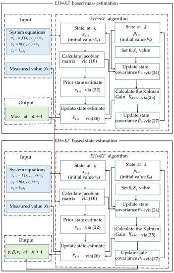
Figure 3.
The joint estimation framework.
We first calculate the prior estimate and the estimation error covariance based on the known initial values. Then, the estimation error covariance of the prior state is used to update Kalman gain. Next, the posterior state is calculated using the Kalman gain and the prior state. Finally, the posterior state error covariance is dynamically updated using Equation (27). The above iterative steps will continuously loop to obtain accurate vehicle state information.
4. Simulation Experiment Platform and Results
The proposed comprehensive estimation schemes implemented in MATLAB/Carsim co-simulation experiment platform are presented in this section. The MATLAB software is used to run the EH∞KF algorithm and the Carsim software is utilized to set up the test traffic scenario of the double lane change. Herein, this section provides two test examples to demonstrate the effectiveness of the proposed method. In addition, the traditional EKF and the proposed estimation method are compared respectively with the reference value.
4.1. The Simulation Experiment Platform
The simulative experimental platform is shown as Figure 4, which is composed of the following three subsystems:

Figure 4.
The co-simulation environment is used for validation of the proposed algorithm.
- The Vehicle Simulation System: It contains two parts: the Driver Model and the Carsim Model. The Driver Model can regulate the steering angle, driving, and braking pedals to follow the target trajectory and target speed. Afterward, the signals of the Steering-wheel Angle Sensor, Accelerator Position Sensor, and Brake Position Sensor are transferred to the Carsim model. Meanwhile, the Carsim model feedbacks the vehicle state to the driver model;
- The Data Acquisition System: It simulates the vehicle measurement system. Firstly, the observation variables (, ) from the vehicle model are collected by the virtual sensors. Simultaneously, the Non-Gaussian measurement noise that simulates the real sensors is added to the actual output observation vectors. Finally, the virtual sensors will pass the measurements to the State Estimation System;
- The State Estimation System is the focus of the simulative experimental platform. It can use the EH∞KF estimator to estimate the vehicle mass, and then take the vehicle mass as the input variable of the next EH∞KF estimator. The last estimation results (, , , ) will compare respectively to the reference vehicle mass and state vectors given by the Carsim Model system.
4.2. Simulation Results
Two different test scenarios were set up to verify the effectiveness of the proposed algorithm: they are the double lane change test on high and low adhesion surfaces, respectively. The vehicle state output values from the software Carsim are used as reference values to compare with the proposed algorithm. The vehicle model parameters from the Carsim software are shown in Table 1

Table 1.
The parameters of vehicle model.
4.2.1. Double Lane Change Test on High Friction Coefficient Road
Figure 5 demonstrates a typical curve of the steering wheel angle on the dry asphalt road in which the tire-road friction coefficient is 0.85 and the initial vehicle speed is 40 km/h. Since the Carsim software provides a manual input interface, we can directly simulate the scenario by giving the specific parameters for the above conditions. It is taken as the input to the vehicle mass estimation. To verify the effectiveness of the vehicle mass estimation algorithm, we set up the initial vehicle mass to be 1000 kg, while the real vehicle mass is 1420 kg. The simulation time is set to 20 s. The estimation results of vehicle mass are demonstrated in Figure 6. In Figure 6, the vehicle mass estimation curve of the EKF algorithm rises rapidly after 5.5 s. After about 12.5 s, the vehicle mass estimation converges to 1250 kg. It is obvious that there is a difference of 170 kg from the reference value. For the EH∞KF algorithm, the vehicle mass estimation curve rises rapidly after 6 s. The vehicle mass estimation converges quickly to 1400 kg after a small fluctuation about 7.7 s. The EH∞KF method is closer to the reference value than the EKF method under the above conditions.
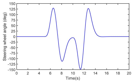
Figure 5.
The steering-wheel angle on high friction coefficient road.
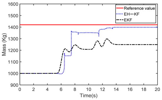
Figure 6.
Vehicle mass estimation on high friction coefficient road.
Figure 7, Figure 8 and Figure 9 show the estimation results of yaw rate, sideslip angle, and vehicle speed using the EKF and the EH∞KF on high friction coefficient road. According to the figures, it can be noticed that the yaw rate, sideslip angle, and vehicle speed estimation curves of the EH∞KF follow reference values better during the simulation process. Nevertheless, the estimation curves of the EKF are far from the reference value. From the locally enlarged view in Figure 7 and Figure 8, it can be seen that the effect of EH∞KF is better than EKF. In Figure 9, the vehicle speed estimation using the EKF has a large fluctuation at the moment of the 6 s, and a huge estimation deviation with a reference value from the 6 s to the 20 s. From Figure 10, Figure 11 and Figure 12, we can see that the mean absolute error of vehicle state estimation using the EH∞KF is lower than the EKF. The RMSE index of the vehicle state is shown in Table 2. The EH∞KF consistently outperforms the EKF. In summary, the estimation performance of the EH∞KF is better than standard EKF under the above conditions.
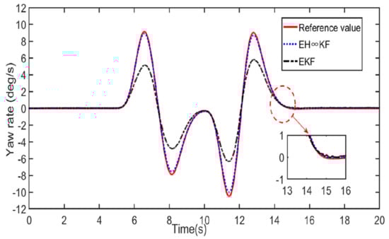
Figure 7.
Yaw rate estimation on high friction coefficient road.
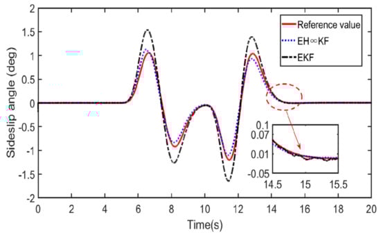
Figure 8.
Sideslip angle estimation on high friction coefficient road.
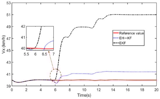
Figure 9.
Vehicle speed estimation on high friction coefficient road.
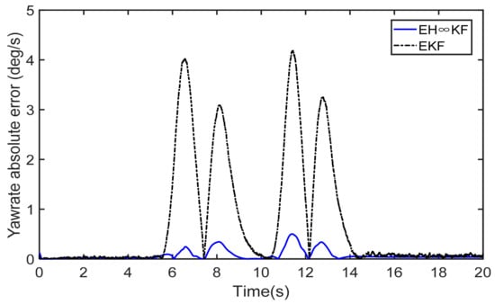
Figure 10.
Yaw rate absolute error on high friction coefficient road.
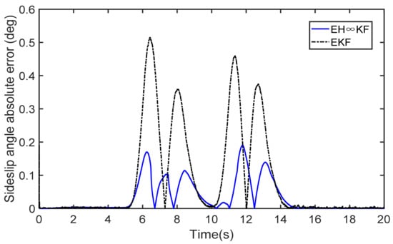
Figure 11.
Sideslip angle absolute error on high friction coefficient.
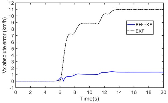
Figure 12.
Vehicle speed absolute error on high friction coefficient road.
Table 2.
RMSE of estimation results on high friction coefficient road.
4.2.2. Double Lane Change Test on Low Friction Coefficient Road
Figure 13 shows a typical curve of the steering wheel angle on the ice-snow road that is taken similarly as the input signal to the vehicle mass estimator. The tire–road friction coefficient is 0.2 and the initial vehicle speed is 20 km/h. Herein, the initial vehicle mass is identified as 1000 kg, while the real vehicle mass is 1420 kg. The simulation time is set to 20 s.

Figure 13.
The steering-wheel angle on low friction coefficient road.
Figure 14 demonstrates the estimation results of vehicle mass based separately on EKF and EH∞KF methods. As described in Figure 14, the vehicle mass estimation curve of the EKF algorithm rises rapidly after 2 s. After about 18 s, the vehicle mass estimation based on the EKF algorithm converges to 1350 kg. It is obvious that there is a difference of 70 kg from the reference value. For the EH∞KF algorithm, the vehicle mass estimation curve rises rapidly after 3.5 s. The vehicle mass estimation converges quickly to 1380 kg after 6 s. At the moment of 14 s, the vehicle mass estimation curve of the EH∞KF fluctuates again. The vehicle mass estimation converges quickly to 1422 kg at the moment of 16 s. The EH∞KF method is closer to the reference value than the EKF method under the above conditions.
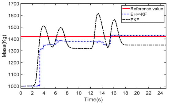
Figure 14.
Vehicle mass estimation on low friction coefficient road.
The estimation results of yaw rate, sideslip angle, and vehicle speed using the EKF and the EH∞KF on low friction coefficient road are shown in Figure 15, Figure 16 and Figure 17. As these figures show, during the simulation process, the yaw rate and sideslip angle estimation curves of the EH∞KF are closer to the reference value comparing with the EKF. Especially in Figure 17, the vehicle speed estimation curve of the EKF cannot follow the reference value better, the vehicle speed estimation using the EKF has a large fluctuation at the moment of the 1.5 s, and a huge estimation deviation with reference value after about 3.5 s. On the other hand, from the locally enlarged view in Figure 15 and Figure 16, it can be seen that the effect of EH∞KF is better than EKF. From Figure 18, Figure 19 and Figure 20, we can see that the mean absolute error of vehicle state estimation using the EH∞KF is lower than the EKF. The RMSE index of the vehicle state is shown in Table 3. The EH∞KF consistently outperforms the EKF. Based on the simulation results above, we can see that the proposed method demonstrates higher precision than the traditional EKF method when system noise and model parameters are uncertain at the same time.
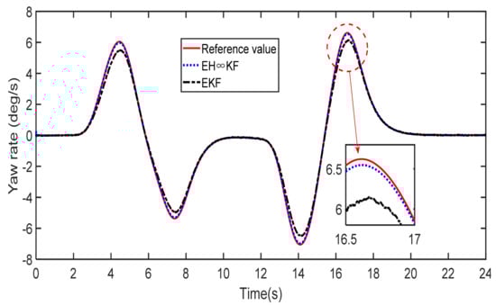
Figure 15.
Yaw rate estimation on low friction coefficient road.
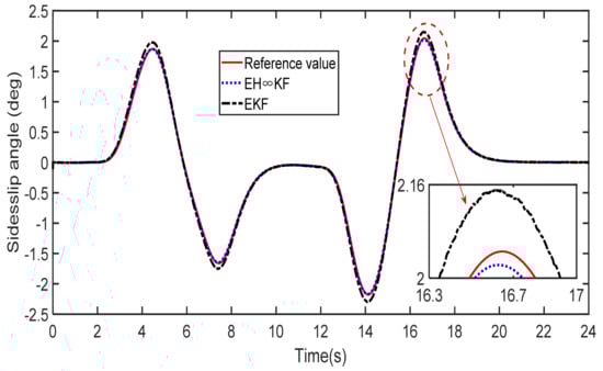
Figure 16.
Sideslip angle estimation on low friction coefficient road.

Figure 17.
Vehicle speed absolute error on low friction coefficient road.
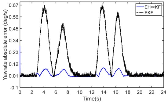
Figure 18.
Yaw rate absolute error on low friction coefficient road.
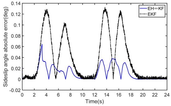
Figure 19.
Sideslip angle absolute error on low friction coefficient road.
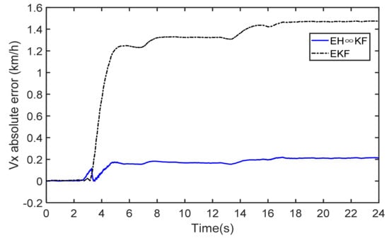
Figure 20.
Vehicle speed absolute error on low friction coefficient road.
Table 3.
RMSE of estimation results on low friction coefficient road.
5. Conclusions
In this paper, a comprehensive estimation scheme is proposed to estimate vehicle state when the noise statistics are unknown and model parameters are inaccurate. The test results indicate that the proposed method has higher estimation accuracy than the existing EKF method. Nevertheless, there are some limitations to this study. We neglect the effect of the road-bank angle in this study. In addition, verification of the algorithm in more complex driving scenarios will also further highlight the superiority of our approach. We will consider the above issues and further optimize our algorithm to improve the estimation accuracy in our future work.
Author Contributions
Conceptualization, F.Z. and G.Y.; model, F.Z. and Y.W.; methodology, F.Z., Y.W. and J.H.; experiment platform, F.Z., G.Y., and H.Z.; formal analysis, F.Z. and S.C.; resources, G.Y. and Y.W.; writing—original draft preparation, F.Z.; writing—review and editing, F.Z., J.H., and D.Z.; supervision, G.Y.; project administration, F.Z., G.Y., and S.C.; funding acquisition, F.Z. and G.Y. All authors have read and agreed to the published version of the manuscript.
Funding
This research was supported in part by National Natural Science Funds for Distinguished Young Scholar under Grant 52025121; in part by the National Natural Science Foundation of China under Grant 51975118; in part by Basic Research Project of Changzhou Science and Technology Plan under Grant CJ20190009; in part by the Higher Vocational College Teacher Professional Leader High-end Training Project in Jiangsu Province under Grant 2019GRFX014; and in part by Qing Lan Project in Jiangsu Province under Grant 202010.
Conflicts of Interest
The authors declare no conflict of interest.
References
- Xu, Q.; Zhou, C.; Huang, H.; Zhang, X. Research on the Coordinated Control of Regenerative Braking System and ABS in Hybrid Electric Vehicle Based on Composite Structure Motor. Electronics 2021, 10, 223. [Google Scholar] [CrossRef]
- Ahangarnejad, A.H.; Radmehr, A.; Ahmadian, M. A review of vehicle active safety control methods: From antilock brakes to semiautonomy. J. Vib. Control 2020, 1–30. [Google Scholar] [CrossRef]
- Wang, Y.; Yin, G.; Li, Y.; Ullah, S.; Zhuang, W.; Wang, J.; Zhang, N.; Geng, K. Self-learning control for coordinated collision avoidance of automated vehicles. Proc. Inst. Mech. Eng. Part D J. Automob. Eng. 2021, 235, 1149–1163. [Google Scholar] [CrossRef]
- Wang, Y.; Geng, K.; Xu, L.; Ren, Y.; Dong, H.; Yin, G. Estimation of Sideslip Angle and Tire Cornering Stiffness Using Fuzzy Adaptive Robust Cubature Kalman Filter. IEEE Trans. Syst. Man Cybern. Syst. 2020, 1–12. [Google Scholar] [CrossRef]
- Tin Leung, K.; Whidborne, J.F.; Purdy, D.; Dunoyer, A. A review of ground vehicle dynamic state estimations utilizing GPS/INS. Veh. Syst. Dyn 2011, 49, 29–58. [Google Scholar] [CrossRef]
- Baffet, G.; Charara, A.; Lechner, D. Estimation of vehicle sideslip, tire force, and wheel cornering stiffness. Control Eng. Pract. 2009, 17, 1255–1264. [Google Scholar] [CrossRef] [Green Version]
- Chen, T.; Xu, X.; Chen, L.; Jiang, H.; Cai, Y.; Li, Y. Estimation of longitudinal force, lateral vehicle speed, and yaw rate for four-wheel independent driven electric vehicles. Mech. Syst. Signal Process. 2018, 101, 377–388. [Google Scholar] [CrossRef]
- Zhu, H.; Li, L.; Jin, M.; Li, H.; Song, J. Real-time yaw rate prediction based on a non-linear model and feedback compensation for vehicle dynamics control. Proc. Inst. Mech. Eng. D J. Automob. Eng. 2013, 227, 1431–1445. [Google Scholar] [CrossRef]
- Ma, H.; Yan, L.; Xia, Y.; Fu, M. Kalman Filtering and Information Fusion, 1st ed.; Springer: Singapore, 2020; pp. 1–8. [Google Scholar]
- Chui, C.K.; Chen, G. Kalman Filtering, 5th ed.; Springer International Publishing: Berlin, Germany, 2017; pp. 19–26. [Google Scholar]
- Li, Q.; Li, R.; Ji, K.; Dai, W. Kalman filter and its application. In Proceedings of the 2015 8th International Conference on Intelligent Networks and Intelligent Systems (ICINIS), Tianjin, China, 1–3 November 2015; pp. 74–77. [Google Scholar]
- Li, X.L.; Zhu, Y.M.; Wang, J.; Han, C.Z. Optimal linear estimation fusion-PartI: Unified fusion rules. IEEE Trans. Inf. Theory 2003, 49, 2192–2208. [Google Scholar] [CrossRef]
- Liu, W.Q.; Wang, X.M.; Deng, Z.L. Robust centralized and weighted measurement fusion Kalman estimators for uncertain multisensor systems with linearly correlated white noises. Inf. Fusion 2017, 35, 11–25. [Google Scholar] [CrossRef]
- Zhu, J.; Park, J.H.; Lee, K.S.; Spiryagin, M. Robust extended Kalman filter of discrete-time Markovian jump nonlinear system under uncertain noise. J. Mech. Sci. Technol. 2008, 22, 1132–1139. [Google Scholar] [CrossRef]
- Nardone, S.C.; Lindgren, A.G.; Gong, K.F. Sept. Fundamental properties and performance of conventional bearings-only target motion analysis. IEEE Trans. Autom. Control 1984, 29, 775–787. [Google Scholar] [CrossRef]
- Toloei, A.; Niazi, S. State estimation for target tracking problems with nonlinear Kalman filter algorithms. Int. J. Comput. Appl. 2014, 98, 30–36. [Google Scholar] [CrossRef]
- Wang, Y.; Xu, L.; Zhang, J.; Dong, H.; Liu, Y.; Yin, G. An Adaptive Fault-Tolerant EKF for Vehicle States Estimation with Multiple Partial Missing Measurements. IEEE/ASME Trans. Mechatron. 2021, 1–10. [Google Scholar] [CrossRef]
- Hrgetic, M.; Deur, J.; Ivanovic, V.; Tseng, E. Vehicle sideslip angle estimator based on nonlinear vehicle dynamics model and stochastic tire forces modeling. SAE Int. J. Passeng. Cars-Mech. Syst. 2014, 7, 86–95. [Google Scholar] [CrossRef]
- Doumiati, M.; Victorino, A.C.; Charara, A.; Lechner, D. Onboard real-time estimation of vehicle lateral tire-road forces and sideslip angle. IEEE/ASME Trans. Mechatron. 2011, 16, 601–614. [Google Scholar] [CrossRef]
- Wenzel, T.A.; Burnham, K.J.; Blundell, M.V.; Williams, R.A.; Fairgrieve, A. Simplified extended Kalman filter for automotive state estimation. Int. J. Model. Identif. Control 2008, 3, 201–211. [Google Scholar] [CrossRef]
- Wada, M.; Yoon, K.S.; Hashimoto, H. High accuracy road vehicle state estimation using extended Kalman filter. In Proceedings of the 2000 IEEE Intelligent Transportation Systems Conference (ITSC), Dearborn, MI, USA, 1–3 October 2000; pp. 282–287. [Google Scholar]
- Baek, S.; Liu, C.; Watta, P.; Murphey, Y.L. Accurate vehicle position estimation using a Kalman filter and neural network-based approach. In Proceedings of the 2017 IEEE Symposium Series on Computational Intelligence, Honolulu, HI, USA, 27 November–1 December 2017; pp. 1–8. [Google Scholar]
- Patra, N.; Sadhu, S. Adaptive Extended Kalman filter for the state estimation of Anti-lock Braking system. In Proceedings of the 2015 Annual IEEE India Conference (INDICON), New Delhi, India, 17–20 December 2015; pp. 1–6. [Google Scholar]
- Hashlamon, I. A new adaptive extended Kalman filter for a class of nonlinear systems. J. Appl. Comput. Mech. 2020, 6, 1–12. [Google Scholar]
- Lin, C.; Gong, X.; Xiong, R.; Cheng, X. A novel H∞ and EKF joint estimation method for determining the center of gravity position of electric vehicles. Appl. Energy 2017, 194, 609–616. [Google Scholar] [CrossRef]
- Montonen, J.; Nevaranta, N.; Lindh, T.; Alho, J.; Immonen, P.; Pyrhönen, O. Experimental Identification and Parameter Estimation of the Mechanical Driveline of a Hybrid Bus. IEEE Trans. Ind. Electron. 2017, 65, 5921–5930. [Google Scholar] [CrossRef]
- Nevaranta, N.; Montonen, J.H.; Lindh, T. Online Estimation of a Mechanical Driveline Parameters of a Hybrid Bus. In Proceedings of the 2018 20th European Conference on Power Electronics and Applications (EPE’18 ECCE Europe), Riga, Latvia, 17–21 September 2018; pp. P.1–P.7. [Google Scholar]
- Wenzel, T.A.; Burnham, K.J.; Blundell, M.V.; Williams, R.A. Dual extended Kalman filter for vehicle state and parameter estimation. Veh. Syst. Dyn. 2007, 44, 153–171. [Google Scholar] [CrossRef]
- Chen, B.-C.; Hsieh, F.-C. Sideslip angle estimation using extended Kalman filter. Veh. Syst. Dyn. 2009, 46, 353–364. [Google Scholar] [CrossRef]
- Wang, Y.; Zhang, F.; Geng, K.; Zhuang, W.; Dong, H.; Yin, G. Estimation of Vehicle State Using Robust Cubature Kalman Filter. In Proceedings of the 2020 IEEE/ASME International Conference on Advanced Intelligent Mechatronics (AIM), Boston, MA, USA, 6–9 July 2020; pp. 1024–1029. [Google Scholar]
- Wang, X.; Zhang, H.; Jiang, X.; Yang, Y. Target tracking based on the extended H-infinity filter in wireless sensor networks. J. Control. Theory Appl. 2011, 9, 479–486. [Google Scholar] [CrossRef]
- Einicke, G.A.; White, L.B. The extended H∞filter—A robust EKF. In Proceedings of the 1994 IEEE International Conference on Acoustics, Speech, and Signal Processing, Adelaide, SA, Australia, 19–22 April 1994; pp. 2595–2599. [Google Scholar]
- Chandra, K.P.B.; Gu, D.-W.; Postlethwaite, I. Fusion of an extended h∞ filter and cubature Kalman filter. IFAC Proc. Vol. 2011, 44, 9091–9096. [Google Scholar] [CrossRef]
- Simon, D. Optimal State Estimation: Kalman, H Infinity, and Nonlinear Approaches, 1st ed.; John Wiley & Sons, Inc.: Hoboken, NJ, USA, 2006; pp. 343–347. [Google Scholar]
- Zhao, J. Dynamic State Estimation With Model Uncertainties Using H∞ Extended Kalman Filter. IEEE Trans. Power Syst. 2017, 33, 1099–1100. [Google Scholar] [CrossRef]
Publisher’s Note: MDPI stays neutral with regard to jurisdictional claims in published maps and institutional affiliations. |
© 2021 by the authors. Licensee MDPI, Basel, Switzerland. This article is an open access article distributed under the terms and conditions of the Creative Commons Attribution (CC BY) license (https://creativecommons.org/licenses/by/4.0/).