Article

ARINC653 Channel Robustness Verification Using LeonViP-MC, a LEON4 Multicore Virtual Platform

Space Research Group, Ctra. Madrid-Barcelona Km. 33.600, Edificio Politécnico, University of Alcalá, Alcalá de Henares, 28805 Madrid, Spain
*
Author to whom correspondence should be addressed.
Electronics 2021, 10(10), 1179; https://doi.org/10.3390/electronics10101179
Submission received: 24 March 2021 / Revised: 7 May 2021 / Accepted: 11 May 2021 / Published: 15 May 2021
(This article belongs to the Section Computer Science & Engineering)

Abstract

:
Multicore hardware platforms are being incorporated into spacecraft on-board systems to achieve faster and more efficient data processing. However, such systems lead to increased complexity in software development and represent a considerable challenge, especially concerning the runtime verification of fault-tolerance requirements. To address the ever-challenging verification of this kind of requirement, we introduce a LEON4 multicore virtual platform called LeonViP-MC. LeonViP-MC is an evolution of a previous development called Leon2ViP, carried out by the Space Research Group of the University of Alcalá (SRG-UAH), which has been successfully used in the development and testing of the flight software of the instrument control unit (ICU) of the energetic particle detector (EPD) on board the Solar Orbiter. This paper describes the LeonViP-MC architectural design decisions oriented towards fault-injection campaigns to verify software fault-tolerance mechanisms. To validate the simulator, we developed an ARINC653 communications channel that incorporates fault-tolerance mechanisms and is currently being used to develop a hypervisor level for the GR740 platform.

1. Introduction

Design complexity and the increase in software-centric systems is an unstoppable trend today. According to the International Technology Roadmap for Semiconductors (ITRS) [1], the number of multicore processors will continually grow in the future. The use of multicore processors offers the opportunity to host different software stacks in each of the cores residing within the same processor, and therefore, increase system performance. However, designing and verifying the embedded software in this type of system represents a considerable challenge.
Embedded software development is carried out according to specific standardized frameworks such as AUTOSAR or ARINC653. The former is mainly used in automotive, while the latter is used in avionics. AUTOSAR uses a top-down approach to describe the hierarchical layer structure of the embedded software. These layers are isolated and can only communicate with adjacent layers through well-defined interfaces. The software architecture defined in standard ARINC653 also separates the application software from the core modules and connects the two separated functional parts via the application executive (APEX) interface. Central to the ARINC653 philosophy is the concept of partitioning, whereby the applications running in the system are spatially and temporally isolated. This feature allows mixing software components with different safety-criticality levels on the same computing platform. AUTOSAR defines a weaker concept of application separation using only memory protection mechanisms. It is possible to build an operating system microkernel that exposes both interfaces to the application software. The work [2] does so and describes the essential characteristics of both frameworks.
If the software suite under development is part of a critical embedded system, in which fault-tolerant requirements must be taken into account, a comprehensive verification of those requirements consumes an increasingly large percentage of resources. In fact, the verification of the software fault-tolerance mechanisms is, most of the time, impossible to be carried out within the deployment target. In this context, the use of virtual platforms provides faster edit–compile–debug cycles for embedded software development. Therefore, virtual platforms have become essential for the development and early verification of embedded software [3,4].
Virtual platforms (VPs) provide software engineers with full simulation environments. Instruction set simulators (ISS) allow the software to be developed and tested with high accuracy in a very early hardware development stage, even long before actual hardware is available. From a hardware perspective, the development of virtual devices can also be addressed throughout VPs. The behavior of these devices can be also verified in the presence of faults as is described in [5]. Virtual platforms enable the concurrent development of hardware and software stacks, shortening their integration time.
These simulation environments range from register transfer level (RTL) simulations with cycle precision to purely accurate ISS-based simulations. Moreover, these simulation environments do not lose their importance and applicability once the first version of the hardware is available. Even though the development effort can be massive, in today’s embedded software development, it is commonly accepted that the use of virtual platforms is essential, especially for hardware-dependent software development (HDS) [6] and when applying agile methodologies [7].

1.1. Motivation

The Space Research Group of the University of Alcalá (SRG-UAH) has developed the software of the control unit of the energetic particle detector (EPD) instrument of the Solar Orbiter mission [8]. Due to the high radiation environment that the spacecraft has to endure, it was necessary to ensure a high fault tolerance for the system. This constraint influence permeated across every hardware and software element and led to the development of Leon2ViP [9], a LEON2-based virtual platform with fault injection capabilities that allowed the fault-tolerance testing of the flight software of EPD. A brief description of how this simulator was used in the verification of the EPD ICU boot software can be found in Section 3.
The increment of software complexity in space has increased the popularity of multicore processors [10]. This fact has encouraged the development of radiation-hardened systems such as the system-on-chip (SoC) GR740 [11], based on a LEON4 quad-core processor. This system results from an initiative led by the European Space Agency (ESA) called the ESA Next Generation Microprocessor (NGMP) [12]. In addition, the agency itself has led the upgrade of the RTEMS operating system [13], which already supports applications for multiprocessor systems in its latest version of November 2018. The LEON4 processor is based on the SPARC Version 8 instruction set architecture (ISA) and is the next evolutionary step in the microprocessors adopted by ESA for its space missions, namely the ERC32 platform and its successors, the LEON [14] family. ERC32 implemented Version 7 of the SPARC ISA. It was developed by TEMIC (now ATMEL) under an ESA contract in the early 1990s. In 1997, the European Space Research and Technology Center (ESTEC) began developing the LEON processor, a high-performance 32-bit processor for European space missions beyond the year 2000. This processor was the successor to the ERC32 and upgraded its ISA to SPARC Version 8. This first version lacked FPU, PCI, and DRAM interfaces, which led to the release of version 2.0 (LEON2) in February 2000 [15]. LEON2-based systems have been used on different spacecraft such as Solar Orbiter, BepiColombo, Gaia, and the recent Chinese Chang’e-4 lunar lander [16,17]. The next evolutionary step is LEON3, which expanded the five-stage LEON2 pipeline to a seven-stage pipeline. It was the first member of the LEON family to support asymmetric and symmetric multiprocessing (AMP/SMP) with up to 16 CPUs. It has been used in the Galileo Global Navigation Satellite System (GNSS) [18]. LEON4 is the current iteration and extends LEON3 with Level 2 cache support, 64-bit internal load/store data paths, and a 64-bit or 128-bit AMBA bus interface. Currently, the fifth version of the processor, codenamed LEON5, is being developed by Cobham Gaisler.
Multicore systems have a higher performance when the software is designed with multicore support. However, the execution becomes non-deterministic due to the pseudo-random arbitration of the cores’ common resources, the use of the cache, and cache snooping. In this scenario, memory upsets produced by radiation have a more significant impact, since the behavior of each core can affect the others, which multiplies the chances of critical failure.
To validate the fault tolerance of satellite on-board systems, we developed a validation-oriented software simulator based on Leon2ViP, which supports, in addition to the original LEON2 and LEON3 architectures, the new multicore systems based on the LEON4 architecture. For the new version of the simulator, we used the LLVM Compiler Infrastructure [19], which is composed of different subprojects related to the static and dynamic compilation of arbitrary programming languages. In this paper, we mainly use the LLVM Core libraries to generate an intermediate code for each instruction and compile and optimize it “just in time”. This platform, called LeonViP-MC, employs dynamic binary translation (DBT) techniques through LLVM coroutines, achieving increased performance in the target software’s execution. In addition, the use of coroutines allows the easy simulation of relevant mechanisms, as the arbitration of shared resources and the accurate counting of the cycles consumed by the various instructions. For the peripheral accesses, we use an average estimation to maintain the reproducibility of the executions.
The simulator also has batch execution capabilities, allowing it to perform multiple binary executions with different fault injection configurations. Binary translations and compiled coroutines can be reused between runs, which avoids the need for compilation in subsequent simulations and saves time when performing the fault-tolerance testing of the target software.
SRG-UAH is currently involved in the development of a hypervisor for the GR740 platform. The development and test of this kind of hardware-dependent software is a complex issue, especially the verification of the fault tolerance and recovery mechanisms that have to be taken into account in every space software development.
The remainder of the paper is organized as follows: relevant related works are detailed in Section 1.2 and paper contributions are presented in Section 1.3. Section 2 describes the original simulator architecture used as a base and the evolution and new features presented in this paper, Section 3 introduces the software used for the fault-tolerance campaign test and the campaign results. Finally, Section 4 contains the conclusions.

1.2. Related Works

Instruction set simulators (ISS) have evolved in order to suit different environments and use cases. They started as simple interpreters that allowed binary code from the target platform to be simulated in a host machine. These interpreters used structures and variables to hold the target architecture registers and data. This approach was accurate but slow. In [20], an instruction-set-compiled simulation was introduced, moving decodification and other arithmetic and logical operations from runtime to the initialization stage, thus removing a considerable overhead from every instruction executed.
If the timing requirements are not essential, dynamic binary translation gives a significant performance leap, allowing one to take advantage of new hardware virtualization tools as seen in QEMU [21]. However, there are some intermediate approaches as gem5 [22] which incorporates the timing models that improve the simulated platform’s accuracy without a substantial performance penalty.
The simulation of a single-core system can be fast when using these techniques since there is only one execution flow running at a time. All system resources are accessible at all times by the core when it needs them. Thus, if a more accurate simulation is needed, the only temporal constraints to be taken into account are those arising from pipeline hazards and bus accesses.

1.2.1. Multicore Simulation Techniques

Multicore systems integrate two or more processing cores that share external resources accessible from the system bus. In this configuration, each core usually has mechanisms to interrupt other cores, and each core can be stopped independently of the state of the other cores. Keeping the cores synchronized is also necessary so that events are generated in order, as having one core running far ahead or behind the others can disrupt the timeline of events. Cache coherence between cores and the arbitration of access to shared resources must also be taken into account.
QEMU is capable of simulating multiprocessor systems. In a first implementation, the simulated cores’ execution was performed in a single thread, arbitrating the execution time between them with a round-robin scheduler. Subsequently, an update of the simulator made it possible to simulate each virtual processor on a separate thread. As in the single-core case, its main focus is on performance. Therefore, it does not provide timing accuracy. There are works, such as [23], that add timing models to QEMU to improve the simulation’s temporal accuracy. These models include atomic instructions and other shared resource accesses and synchronize all cores’ execution whenever one of them reaches a time-dependent system event or instruction.
In contrast, gem5, in its most accurate configuration, iterates through each core on every cycle while applying a synchronization model. In this case, the temporal accuracy is very high, but the performance decreases significantly.
The R2VM simulator [24] uses a custom mechanism inspired by coroutines called fiber to improve the performance in synchronizing the different simulated cores. This mechanism launches each hardware core in a coroutine and the DBT generates yields to the next fiber whenever the pipeline model detects that it has to wait for some cycles. The event loop is also launched in a fiber. The results of this work show that cycle-level simulation with this mechanism is nearly 100 times faster than gem5. They also claim that functional simulation with R2VM performs better than QEMU. In this implementation the DBT is tailored using the assembly code of the ×86 platform, which limits its portability and requires more effort to develop, in contrast to the LLVM approach explained in the next Subsection.

1.2.2. LLVM as a Simulation Support Tool

As seen in the last Section, a cycle-accurate multicore simulation needs to synchronize actions that may affect other devices or cores, in addition to the execution of binary instructions. LLVM is a compiler infrastructure that provides a high-level assembly language called intermediate representation (IR), which can be further translated to the machine code of different target architectures. LLVM allows compiling and optimizing IR code on demand, or “just in time”, for the host machine. This feature makes LLVM highly suitable for the implementation of DBTs. Its infrastructure provides a specific API that can be used in programs implemented in the C++ language. Various studies have verified that the generated code has a much higher performance than that obtained through other DBTs [25,26,27] or QEMU’s Tiny Code Generator (TCG) [28]. However, LLVM compilation and optimization processes are expensive. The overhead introduced by them can lead to a higher total execution time when considering the compilation and optimization steps than that obtained by using simpler DBTs.
There have been different approaches to increase the global performance of LLVM-based simulators. Some works have applied an heuristic that only compiles execution blocks that are executed on several occasions [25,26]. Other works have focused on optimization. For example, [27] reduces the optimization passes so their JIT compilation takes less time with a minor execution performance drawback and [29] optimizes LLVM IR before compiling it, reducing the amount of code that has to be compiled from the beginning. Finally, some works have delegated the JIT tasks to another independent thread as [28], which uses QEMU TCG to generate the code and the LLVM thread to optimize the blocks in runtime, increasing performance over time.

1.3. Paper Contribution

This paper presents a simulator of the GR740 quad-core processor that combines dynamic binary translation through LLVM and coroutines and works at the instruction level with cycle estimation. This simulator has fault injection capability and is designed to run extensive software-fault tolerance test campaigns. To increase test throughput during a campaign, LeonViP-MC can reuse the compiled LLVM code of the binary target’s instructions in subsequent executions.
Since injected faults can propagate errors during execution, we had to maintain a relatively low level of abstraction of the execution simulation. For this reason, and although it does not fully simulate the pipeline of the processing units, LeonViP-MC implements an instruction-level simulation that considers the internal timing and the dependencies between instructions in order to achieve cycle accuracy.
Simulator’s core arbitration mimics the hardware without the pseudorandom results caused by the hardware nature, which may produce differences in the same software execution due to the bus accesses and other particularities. Our virtual platform avoids those inconsistencies so the execution of a software without external intervention is reproducible. This is important for the fault injection testing campaigns, in which errors may lead to different execution paths and we need to keep track of the differences.
The modularity of the internal components of the simulator allows the efficient implementation of new devices and interfaces. The architecture of the simulator itself facilitates its future adaptation to other architectures. For this purpose, it would be necessary to add the necessary methods to generate the LLVM intermediate representation corresponding to the target’s instruction set.
Finally, the LLVM-based binary translator allows the virtual platform to be easily adapted to different host systems. Performance in all cases would be similar, relative to the host platform’s power, as the generated code is compiled and optimized for the machine that runs it.

2. Multicore Virtual Platform

As mentioned in the previous Section, the simulated target platform is the GR740 system-on-chip (SoC). This system deploys a quad-core LEON4 processor [11]. This processor supports the SPARC V8 instruction set architecture. In addition to the four LEON4 processing units, this device deploys interfaces and peripherals commonly used in spacecraft computers and interconnected by an AMBA high-performance bus (AHB). As expected for space systems-oriented hardware, the processor and the other cores that comprise the SoC incorporate fault-tolerant capabilities. This section is organized as follows: Section 2.1 describes the previous Leon2ViP simulator used as a basis. Section 2.2 presents the design choices and development of the multicore simulator presented in this work. Finally, Section 2.3 explains the mechanisms implemented in the presented simulator to perform the fault-injection campaign tests.

2.1. Base Single-Core Virtual Platform

The original implementation of the simulator presented in this paper was carried out in support of the development of the software of the instrument control unit (ICU) of the energetic particle detector (EPD) on board the Solar Orbiter [8]. Solar Orbiter is a joint mission between ESA and NASA that was launched on 10 February 2020. In this mission, the SRG-UAH is responsible for the EPD instrument. Specifically, the SRG has been in charge of designing the common data processing unit (CDPU) of EPD’s ICU and the on-board software running on it. SRG-UAH developed a virtual platform called Leon2ViP (LEON2 Virtual Platform) based on the previous development of LEON3 [9] and has been successfully used to develop and verify the ICU software [30].
Leon2ViP consisted of a SPARC Version 8 LEON3 Instruction Set Simulator (ISS), a configurable cache controller, the AMBA AHB main system bus, and some primary devices connected to it. In the base version, the implemented devices were the memory controller with EDAC capabilities and an AMBA advanced peripheral bus (APB) bridge. Several devices connected to the APB were also simulated, such as the general purpose timer (GPTimer), a universal asynchronous receiver–transmitter (UART), and the interrupt controller. Some of the above only implemented basic single-core functionality and had to be upgraded to support the features of the multicore platform.
The ISS implements a variant of the technique called compiled instruction set simulator [31]. We decode the executable code section of the binary at initialization, and these decoded data are stored in a precompiled instruction cache. This cache contains one entry for each of the instructions that make up the code section. If any instruction is modified at runtime, the corresponding entry in the instruction cache is updated. Each entry stores a structure in the format shown in Figure 1. The cache contains every datum needed at runtime computations with invariant operands. These data include, for example, the operation codes of the instruction, the destination address in case the instruction is a call, or the possible immediate data used by the instruction with its corresponding sign extension so that they can be directly used at runtime.
By performing this static analysis of the instructions, the simulator can also keep track of the registers and memory operations used by each instruction. These data are then used to calculate the cycles consumed in the execution of each instruction. This information allows the simulator to perform the runtime cycle counting and to achieve cycle accuracy.
Finally, the data stored in this structure also allow the generation of debugging traces at runtime. Examples of data that can be used for this purpose are the instruction’s type (arithmetic and logical operations, load/store instructions, conditional branches, etc.) or the memory bytes that are read or written by it.
In the latest version of the simulator, the size of the structure has been increased to support new features and properties of the GR740 platform. An instance of the precompiled structure in the latest version of LeonViP-MC has a size of 144 bytes. For example, the EPD ICU boot software has 8752 instructions, so the precompiled code occupies about 1.2 megabytes of host memory. The use case presented in Section 3 has 10,551 instructions, which translates to about 1.45 megabytes of host memory. Both of these examples represent acceptable memory usage compared to the improvements obtained with this approach.

Cycle Accuracy

Since our simulator does not simulate the complete processor pipeline, we have to calculate the number of cycles used to execute each instruction. This calculation takes into account the characteristics of the instruction itself, as well as those of the previous instruction. In addition, it is also necessary to estimate the cycles used in accessing the various peripherals. In this way, we distinguish three types of cycle increments per instruction:
  • Static cycle counting—The simulator assigns, for each instruction, the number of cycles it consumes nominally according to the LEON4 processor specification;
  • Dynamic cycle counting—The LEON4 specification details those cases where having two specific instructions executed one after the other causes execution delays. These delays can be caused by data hazards or by the intrinsic nature of the instructions. During instruction execution, the simulator temporarily stores the data needed to calculate this delay effectively.
  • Peripheral access cycle counting—When an instruction needs to access data or other resources beyond the processor cache, accessing the AHB bus may cause a delay in execution. This delay may be caused by the intrinsic speed of the peripheral and/or because another core is using the bus in the multicore scenario. Since this delay is pseudo-random in real hardware, we estimate the average cycles per access based on empirical tests performed on the real GR740 platform.
The simulator keeps track of the current execution cycle by adding the various cycle increments to the bus access wait cycles. These cycles are fixed so that two executions of the same binary with the same initial conditions produce the same result. This reproducibility is key to using the simulator for on-board software development, debugging, and validation.

2.2. Multicore Simulation

The next step in developing the simulator was to provide it with the ability to simulate the execution of multiple processing cores. To synchronize the instruction execution in the different cores and the bus accesses and control the global execution variables, we added a new component called the orchestrator. The orchestrator synchronizes each core so that it is only allowed to continue its execution if its local cycle counter is behind the orchestrator’s global counter. When allowed, it will execute until the end of the current instruction or when it needs to access the bus. The local cycle counter is incremented by the static and dynamic cycle counters. This increment could put the local counter a few cycles ahead of the global counter, forcing the core to wait until the global cycle counter reaches it to continue executing. The orchestrator also arbitrates bus accesses, which, together with the global cycle control, ensures that the cores will not interfere with each other’s execution. It is worth mentioning that the original simulator has been updated to support the LEON4 instruction set architecture and its capabilities in single and multicore configurations.

2.2.1. Multicore Simulation with Threads

The initial version of the multicore simulator launched five separate threads, each of them running exclusively on a specific host core. One of the threads executed the orchestrator, while the rest were dedicated to simulating the execution of the target cores. In this version, the orchestrator synchronized the cores at the cycle level, giving the cores exclusive access to the bus. As mentioned above, each core has a local cycle counter. When a core exceeded the orchestrator’s global counter, it stopped and incremented an atomic variable that kept track of how many cores were “halted”. The orchestrator would perform core synchronization and bus arbitration and then release each core. Threads were synchronized using the mentioned atomic variable and spinlocks, as our tests showed that other mechanisms which consumed fewer resources, such as mutual exclusion locks, provided lower performance.
This design proved functional, but there were some performance issues caused by thread synchronization compared to the single-core version. For this reason, we decided to address the main performance bottlenecks, namely instruction execution and core orchestration. A performance comparison between this approach and the final implementation, described in the following paragraphs, is shown in Section 2.3.

2.2.2. Multicore Simulation with LLVM and Coroutines

As mentioned earlier, one of the leading performance bottlenecks was core orchestration. The use of multithreaded algorithms on a host platform with multiple processor cores is most suitable when the tasks to be performed can be parallelized independently, and these tasks consume a significant amount of execution cycles. However, when it is necessary to synchronize the threads’ execution every few cycles, as in our case, the synchronization overhead itself causes the overall performance to drop significantly. To reduce such overhead, we had two different options: to decrease the number of times the cores synchronize or not to use threads at all in the implementation. The first approach could be implemented by synchronizing only when the bus acquiring or releasing cycles is interrupted, but the cores would still need to be synchronized at cycle level or their individual execution may advance faster than the other cores. The second approach involved going back to the single-threaded paradigm, but since each core had its particular context, a simple loop running all the cores caused too much data transfer and unnecessary function calls. We could address this problem by using coroutines as in [24].
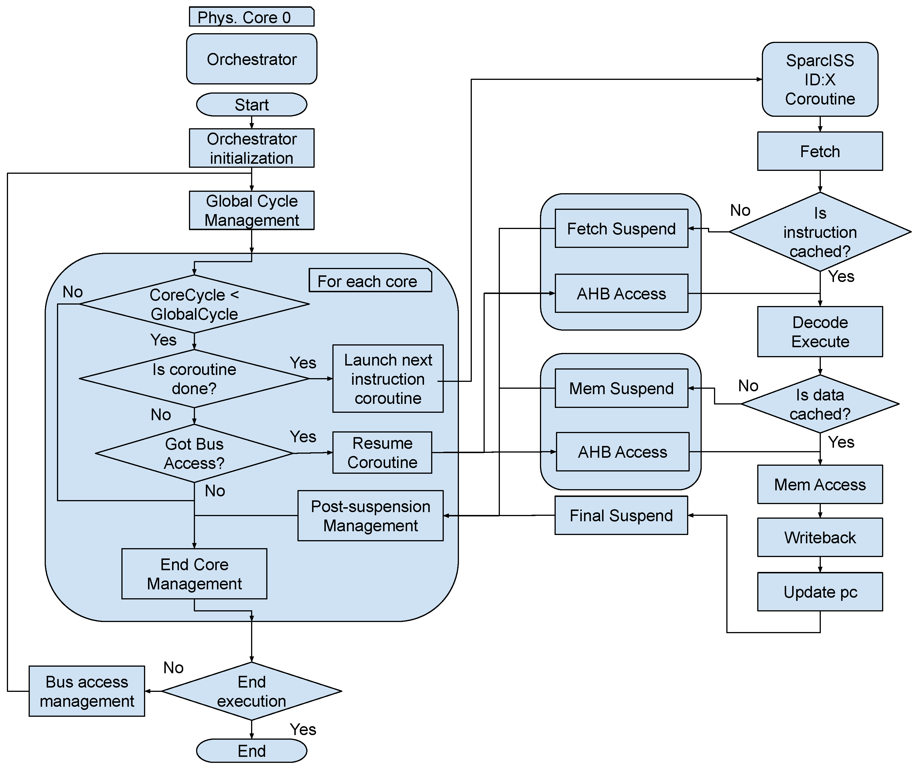
Coroutines allow calling, suspending, resuming, and destroying functions similarly to how we do it in the multicore version but in a single-threaded configuration. In this case, the simulated instructions are coded and executed in the form of coroutines. The orchestrator will call or resume the coroutines of the instructions that each core executes. The coroutines will suspend whenever bus access is required, relinquishing control back to the orchestrator. The orchestrator will be in charge of resolving and ordering the accesses, resuming the coroutines accordingly. This paradigm allows us to significantly improve performance, being able to change the context quickly with almost no overhead.
The other bottleneck that we addressed was the instruction execution. The instruction execution can be broken down into different stages or phases: fetch; decodification; execution; memory access; writeback; and exception handling. Fetching is always performed for each instruction and involves access to either the memory or the cache. Decoding is not performed at runtime, but during initialization, in the binary load, where the decoded data are stored in the structure corresponding to the precompiled instruction cache. Execution, memory access, and writeback vary depending on the instruction and may also require memory access. Exception handling is performed by the orchestrator each time an exception occurs in a core.
Figure 2 shows the simulator’s main loop. In an ideal case, with the required instruction and data cached, the orchestrator will call the instruction execution coroutine, and it will fetch from the cache, execute, access cache if needed, and also update registers if needed. Then, it will terminate and pass control to the orchestrator, which will call the next coroutine after the global cycle counter surpasses the core’s local counter. This scenario could also be done with a function call that returns to the same point, but if the core needs to access the bus, it may have to wait if the bus is busy. At this point, the coroutine can be suspended until the core receives exclusive access to the bus. The cycle counter would be updated since the core is halted, but the whole system continues to run.
To reduce the number of host instructions required to execute a single target instruction, we used dynamic binary translation using LLVM coroutines. Initially, when we decode the instructions and store them in the precompiled instruction cache, we build the corresponding LLVM coroutines using LLVM intermediate representation (IR). This IR code implements the whole instruction execution and calls external C++ routines to check if the instruction or the data it uses are cached. The coroutine will suspend if it has to access the bus, if an exception occurs or when the execution ends properly. The IR code performs the rest of the operations needed to execute the instruction (e.g., arithmetic and logic operations or register access and writeback). The LLVM IR code is stored as raw strings within the precompiled instruction cache.
Building the LLVM IR is a quick process that uses data from the decodification stage and has to be done only once per each instruction code, independently of the instruction’s address. The compilation could be done right after the code is built, but compiling an optimized code is more time consuming than building the code. For this reason, we decided to use just-in-time compilation (JIT) to generate the final host machine code, compiling the instructions only when they were going to be required.
When an instruction is to be executed, the simulator checks whether the LLVM coroutine for that specific instruction code has been previously compiled. If not, the IR coroutine is compiled, and its pointer is stored in the corresponding entry of the compiled instruction cache. The coroutine receives as arguments the pointers to the data corresponding to the specific core that is executing the instruction. The LLVM code will load from these data only the variables necessary to perform the execution. Since all cores share the precompiled instruction cache, they can reuse the code that has been previously generated as the result of the execution of another core.

2.3. Fault-Tolerance Campaign Testing Mechanisms

As mentioned above, the simulator’s primary purpose is to support the development of on-board software and test its behavior against errors caused by radiation. The simulator allows injecting errors in the different memory banks. In a single test, we can inject multiple memory words with errors, which can be one or more bits stuck at zero or one, combined in the same word. We can also inject an error when the execution reaches a given address, allowing the simulator to test the system in the worst possible scenario, i.e., an error appears when the software is to access a memory address in a region that would have been tagged as safe.
To improve error injection testing performance, we added a batch mode that reuses the LLVM coroutines compiled from previous runs. With this feature, running a batch of error injection tests in different configurations, as in [32], is significantly faster than running the simulator once per run, which would require compiling and optimizing the LLVM code each time. In addition, since our simulator uses a single thread of execution, it can effectively parallelize test runs, reducing the overall execution time on host machines with multiple processing cores.
We tested both the multithreaded and LLVM coroutine approaches by running different applications. Specifically, we used tests provided along with the RTEMS operating system [13] with symmetric multiprocessing (SMP) support and the use case detailed in the following Section. Table 1 displays the difference in performance between the implementations. The RTEMS tests are compiled for the GR740 and some of them use a different number of cores. It is worth noting that the first run spends more time due to compilation passes and LLVM optimization, but the subsequent runs that reuse the code usually have a substantial performance increase over the original implementation. If the total number of different instructions is low, as in the smpatomic01 and smpmigration01 tests, the compilation time of LLVM coroutines is diluted in the total execution time, and therefore, the performance gain in subsequent executions is reduced.
It is important to remark that the thread approach uses five host machine cores that must be exclusively assigned to the simulator to synchronize the cores and keep them moving forward together. In contrast, the LLVM coroutines approach uses only one host machine core, so it could be possible to run five different instances of this approach with different subsets of the same fault injection campaign using the same computational resources that one instance of the thread approach employs. Therefore, the performance leap is even more significant.

3. Use Case: ARINC653 Message Channel Robustness Verification

Radiation-induced single event effects (SEEs) are the primary cause of space software malfunctions. In the worst-case scenario, they could lead to the complete loss of a mission. To analyze the effects of radiation from a software point of view, we need to categorize the types of potential failures. In a broad sense, SEEs can be classified either as single-event upsets (SEUs) or single-event latch-ups (SELs). The former, known as “bitflips”, are transient and correctable, while the latter brings about permanent faults, known as “stuck-at” bits, and are uncorrectable. A broad description of SEEs effects in spacecrafts is described in [33].
Figure 3 shows the real (left) and simulated (right) execution platforms of the hypervisor software being developed for the GR740 multicore platform. When developing this type of hardware-dependent software, it is essential to have virtual platforms that allow running the same target binary as if on the real system, but in a more controlled and deterministic way. This is fundamental in evaluating the fault detection, isolation and recovery (FDIR) mechanisms implemented in the software design. To do so, all random faulty situations in memory brought about by radiation have to be artificially and systematically reproduced during the verification phase. This can only be achieved by the use of virtual platforms which provide debugging and fault injection capabilities, which are unattainable otherwise.
Memory bitflips are resolved at runtime using error detection and correction (EDAC) mechanisms, usually combined with memory scrubbing techniques. On the other hand, in the case of permanent errors in the memory deployment area of application software, an updated binary version that avoids the damaged areas must be uploaded to the spacecraft. This critical operation is done by the boot software, which will wait and remain active until the images have been repaired through service tele-commands that allow memory patch, dump, and check operations. The boot software runs on ROM and cannot be corrupted, which on the other hand, prevents its update. This impossibility of updating makes it necessary to check the FDIR mechanisms implemented in the boot software thoroughly. However, although boot code runs on ROM, it needs some SDRAM allocation for the system startup variables. These runtime variables are usually allocated in the stack section, which is determined at boot time to avoid any damaged locations.
This approach has been successfully used in the verification of EPD’s ICU boot software (BSW) on board the Solar Orbiter. The following are several issues related to BSW verification that highlight the confidence in the results obtained using virtual platforms for critical software verification:
  • The verification of the BSW boot process asks for the possibility of the corruption of application binaries stored in the EEPROM or permanent faults in the SDRAM application deployment areas. First of all, the injection of permanent faults in real hardware is not technically achievable in a non-intrusive manner. Secondly, in order to carry out an exhaustive verification, each memory location of EEPROM and SDRAM areas must be individually corrupted and BSW behavior tested. This leads to a very huge amount of BSW runs. Although each just takes a few seconds, completing the entire test would take months running in a single machine. The use of virtual platforms allows the injection of permanent errors and can significantly reduce the verification time spent since several instances of the Virtual Platform can be run in parallel on different real machines, thus shortening the overall testing time [30].
  • Although BSW is not deployed in the SDRAM, but is executed directly in the PROM to increase its reliability, it still uses SDRAM to map the program stack and global variables. In order to avoid the malfunction of the BSW itself due to SDRAM permanent faults, stack and runtime variables must not be statically allocated. Therefore, during system startup, an error-free memory area is searched for and used for nominal boot as is described in [32].
  • The BSW is a criticality category B software, which cannot be replaced during the mission, so testing this kind of critical software must cover 100% of the source code statement and decision paths. Coverage is a major concern for dependability because parts of the code that are never executed during a test workload run cannot be properly verified. So, the efficient coverage of an exception handling code is an essential concern. Regarding BSW, the developed framework and figures are described in [7].

3.1. System under Test

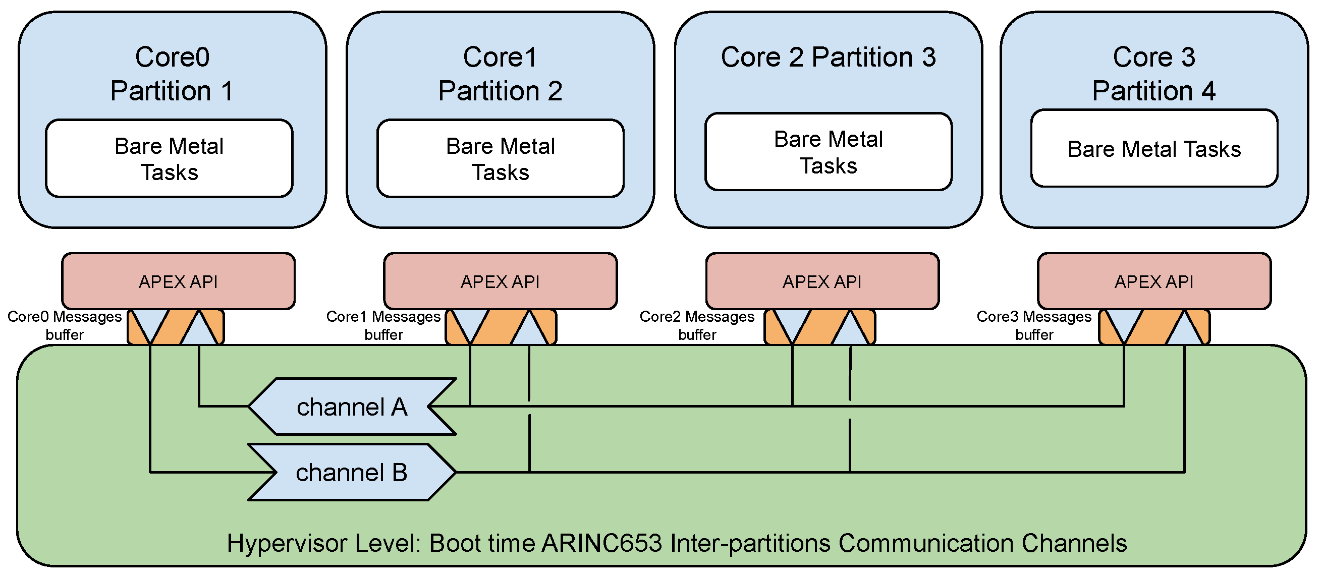
Figure 4 shows the basic architecture of the system under test. It is built on a GR740 board. The system is composed of four cores, each one running an ARINC653 partition. The software belonging to each partition uses an Application Executive API (APEX) to access the communication services offered by a hypervisor layer. At partition boot time, there are two defined message channels, channel A and channel B, which interconnect the bootstrap core (CORE0) with the remaining cores to achieve a smooth and synchronized boot of the whole system. The bootstrap core uses the former channel to receive the boot information of the other cores. The latter channel is used to communicate the responses and orchestrate the whole system’s boot.
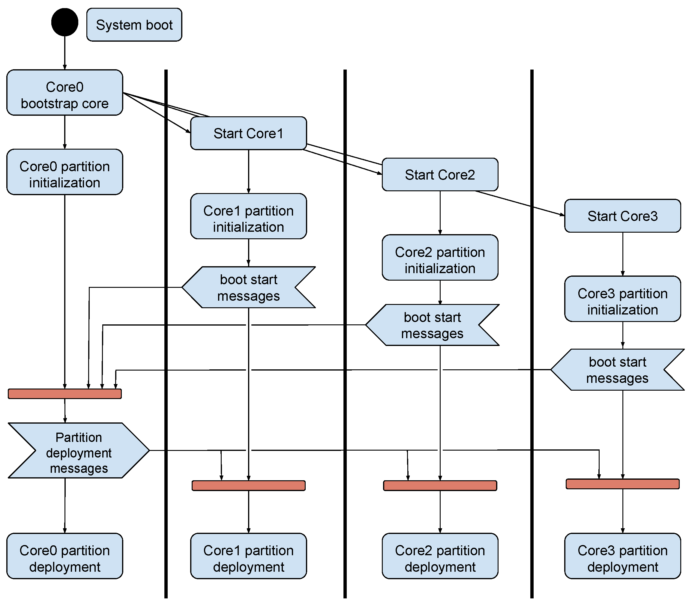
Figure 5 shows an activity diagram of the boot process. After system startup, the bootstrap core carries out some basic system checking and starts the other cores. Each core carries out its own partition initialization. This approach benefits from a faster boot process since several tasks are carried out in parallel. All these processes are synchronized using software barriers, where each core’s software waits for the other cores to complete their operation.

3.2. Channel Buffer Provisioning Approach

Each core has its own input/output message buffer. These buffers are allocated in SDRAM memory and are critical elements for the system’s reliability since a permanent error in any of them prevents the normal boot of the system and the loss of the mission. To improve fault tolerance, we followed a buffer redundancy approach. Rather than having N replicated buffers for each core, a buffer’s pool has been allocated. This way, any core can use any message buffer present in the pool that is free of permanent errors.
The use of spare resource pooling is not new, although this approach has been progressively replaced by hardware mechanisms when the amount of available memory was low. However, nowadays, the total available memory in space systems exceeds the needs of the software. As mentioned above, SRG-UAH has been involved in the hardware/software development of the instrument control unit (ICU) of the energetic particle detector (EPD) on board the Solar Orbiter. The ICU has 256 MB of SDRAM memory, while the application software is around 300 KB, and about 10 MB are used for data buffer by each of the four EPD’s sensors. These figures mean that the software uses less than 20% of the available memory. In any case, the idea behind this buffer over-provisioning approach is not to replace the memory fault-tolerance mechanisms implemented in hardware but to complement them from a software perspective so that the final system’s overall reliability is improved.
As is pointed in [34] “A little redundancy, thoughtfully deployed and exploited, can yield significant benefits for fault tolerance; however; excessive or inappropriately applied redundancy is pointless”. The modest over-provisioning of critical memory resources can be used today to reduce the impact of permanent faults without incurring an excessive memory usage penalty. By design, such systems still become alive until no further spare resources are available. As shown in Figure 6, twelve buffers are allocated in SDRAM memory at boot time, and in parallel, each core tests and selects a free error buffer. There must be four out of twelve buffers available for a normal startup of the system.

3.3. Fault Injection Campaign

This section describes the fault injection campaign to verify that the message buffer pooling approach followed works correctly. As previously described, the buffers pool contains twelve buffers from which four buffers are selected that are free of permanent errors. The system boots as long as there are four buffers available. If there are not enough buffers available, the system halts and enters in a safe mode.
To verify the buffers’ selection mechanism, we should test all combinations with permanent errors in buffers. For example, of the 12 buffers available, there may be permanent failures in only one or several of them. From a general point of view, these could be k buffers, with k between 1 and 12, affected by permanent errors. The total number of combinations without repetition is given by the binomial coefficient, as can be seen in Equation (1), where n is the number of buffers available:
n k = n ! k ! ( n k ) !
The worst situation that still allows a successful boot is achieved when eight buffers suffer permanent errors, in this case, n = 12, k = 8, as is shown in Equation (2):
12 8 = 12 ! 8 ! ( 12 8 ) ! = 495 combinations
The total number of faulty configurations to be tested was obtained by sweeping k between 1 and the buffers pool size, as is described in Table 2. In addition to them, the error-free nominal execution, known as golden run, should be added:

3.4. Results

While developing the ARINC software, LeonViP-MC has been used to ensure that the fault-tolerance mechanisms worked adequately since some compiler optimizations do not consider that the RAM could change randomly due to an external factor. The use of the simulator allowed us to incorporate mechanisms that prevent software undefined behavior such as executing wrong instructions or doing unaligned memory accesses.
Once the ARINC software development finished, we made a fault injection campaign that enclosed the 12 different buffer pool corruption combinations and the nominal case without injected faults. LeonViP-MC was capable of running the 4096 tests in 6 min and 28 s approximately, showing that 3797 ended up appropriately and the 299 remaining aborted their execution after the buffer checking process without reaching an undefined behavior. Since four buffer pools are needed for the program to initialize, every test with more than eight corrupted buffers does not start the partition’s initialization and deployment.
In terms of performance, this campaign executed a total of 1,592,350,631 instructions in approximately 387.92 s, which means that the average performance for the execution is around 4.1 MIPS. The machine used for executing the campaign and the performance tests in Section 2.3 was an Intel i5 9600 K 3.7 GHz with 8 GB of DDR4 RAM.

4. Conclusions

Space software has been incrementing in terms of its complexity in recent years. The need for more computational power is leading to the development and usage of multicore processors in on-board space applications. Furthermore, in recent years, space agencies and companies have been planning programs with greater scopes. These programs include a permanent human presence on the Moon and its orbit, as in the NASA Artemis Program, or the Chinese Lunar Exploration Program, or even on Mars’ surface with the SpaceX Starship spacecraft. Both the Moon sphere of influence and Mars have environments where radiation involves a greater risk than in the Earth’s orbit.
This paper presents the implementation of a multicore simulator designed to run fault-tolerance test campaigns. In order to simulate the multicore environment, LLVM and coroutines have been implemented. The LLVM coroutines that implement instructions have been reused between executions of the same software during the campaign to improve the global simulator performance. The simulator mimics the GR740 but can be configured to adapt to other LEON platforms. Furthermore, its modularity allows the implementation of other multicore processors with a different instruction set architectures.
A test campaign for a fault-tolerant ARINC653 message channel application has been carried out as a use case. This application detects corrupted message buffers and starts messaging only after checking whether there are enough correct buffers available. To validate these procedures, we had to test a large number of faulty configurations, demonstrating the virtual platform’s fault injection capabilities.
The development of virtual platforms like LeonViP-MC has a double positive impact on embedded software development since its incorporation in the development toolchain gives us a better understanding of the hardware and its particularities. This also allows us to implement and use new features and paradigms that improve the embedded software development process and are almost impossible or challenging to apply in a real hardware environment.

Author Contributions

Conceptualization, J.S., A.d.S. and P.P.; methodology, J.S. and A.d.S.; software, J.S. and A.d.S.; validation, J.S. and A.d.S.; formal analysis, J.S.; investigation, J.S.; resources, P.P., Ó.R.P., A.M.H. and S.S.; data curation, J.S.; writing—original draft preparation, J.S., A.d.S.; writing—review and editing, J.S., A.d.S., P.P., Ó.R.P., A.M.H. and S.S.; visualization, J.S. and A.d.S.; supervision, P.P., Ó.R.P., A.M.H. and S.S.; project administration, P.P., Ó.R.P., A.M.H. and S.S.; funding acquisition, P.P., Ó.R.P., A.M.H. and S.S. All authors have read and agreed to the published version of the manuscript.

Funding

This work has been supported by the Comunidad de Madrid and the Universidad de Alcalá, Spain under the grant CM/JIN/2019-032 and by the Youth Employment Initiative (YEI) of the European Social Fund (ESF), under the Operational Program of Youth Employment (POEJ), grant PEJD-2018-AI/TIC-11912.

Conflicts of Interest

The authors declare no conflict of interest.

References

  1. Chan, W.J.; Kahng, A.B.; Nath, S.; Yamamoto, I. The ITRS MPU and SOC system drivers: Calibration and implications for design-based equivalent scaling in the roadmap. In Proceedings of the 2014 IEEE 32nd International Conference on Computer Design (ICCD), Seoul, Korea, 19–22 October 2014; pp. 153–160. [Google Scholar] [CrossRef]
  2. Zuepke, A.; Bommert, M.; Lohmann, D. AUTOBEST: A united AUTOSAR-OS and ARINC 653 kernel. In Proceedings of the 21st IEEE Real-Time and Embedded Technology and Applications Symposium, Seattle, WA, USA, 13–16 April 2015; pp. 133–144. [Google Scholar] [CrossRef]
  3. Rocha, F.; Ost, L.; Reis, R. Soft Error Reliability Using Virtual Platforms; Springer: Berlin/Heidelberg, Germany, 2020. [Google Scholar]
  4. Akram, A.; Sawalha, L. A Survey of Computer Architecture Simulation Techniques and Tools. IEEE Access 2019, 7, 78120–78145. [Google Scholar] [CrossRef]
  5. Muñoz-Quijada, M.; Sanz, L.; Guzman-Miranda, H. A Virtual Device for Simulation-Based Fault Injection. Electronics 2020, 9, 1989. [Google Scholar] [CrossRef]
  6. Engblom, J. Virtual to the (near) end—Using virtual platforms for continuous integration. In Proceedings of the 2015 52nd ACM/EDAC/IEEE Design Automation Conference (DAC), San Francisco, CA, USA, 8–12 June 2015; Volume 2015. [Google Scholar] [CrossRef]
  7. Parra, P.; da Silva, A.; Óscar, R.P.; Sánchez, S. Agile Deployment and Code Coverage Testing Metrics of the Boot Software on-board Solar Orbiter’s Energetic Particle Detector. Acta Astronaut. 2018, 143, 203–211. [Google Scholar] [CrossRef]
  8. Rodríguez-Pacheco, J.; Wimmer-Schweingruber, R.F.; Mason, G.M.; Ho, G.C.; Sánchez-Prieto, S.; Prieto, M.; Martín, C.; Seifert, H.; Andrews, G.B.; Kulkarni, S.R.; et al. The Energetic Particle Detector—Energetic particle instrument suite for the Solar Orbiter mission. A&A 2020, 642, A7. [Google Scholar] [CrossRef]
  9. da Silva, A.; Sánchez, S. LEON3 ViP: A Virtual Platform with Fault Injection Capabilities. In Proceedings of the 2010 13th Euromicro Conference on Digital System Design: Architectures, Methods and Tools, Lille, France, 1–3 September 2010; pp. 813–816. [Google Scholar] [CrossRef]
  10. George, A.D.; Wilson, C.M. Onboard Processing With Hybrid and Reconfigurable Computing on Small Satellites. Proc. IEEE 2018, 106, 458–470. [Google Scholar] [CrossRef]
  11. COBHAM. GR740 Quad Core LEON4 SPARC V8 Processor 2020 Data Sheet and User’s Manual. 2020. Available online: https://www.gaisler.com/doc/gr740/GR740-UM-DS-2-4.pdf (accessed on 3 May 2021).
  12. ESA. GR740: The ESA Next Generation Microprocessor (NGMP). 2020. Available online: http://microelectronics.esa.int/gr740/index.html (accessed on 3 May 2021).
  13. Krutwig, A.; Huber, S. RTEMS SMP Final Report; Technical Report, Embedded Brains GmbH and ESA; ESA: Paris, France, 2017. [Google Scholar]
  14. ESA. Leading Up to LEON: ESA’s First Microprocessors. 2013. Available online: http://www.esa.int/Enabling_Support/Space_Engineering_Technology/Leading_up_to_LEON_ESA_s_first_microprocessors (accessed on 3 May 2021).
  15. Gaisler, J. Leon-1 processor-first evaluation results. In Proceedings of the European Space Components Conference: ESCCON 2000, Noordwijk, The Netherlands, 21–23 March 2000; Volume 439. [Google Scholar]
  16. ESA. LEON: The Space Chip that Europe Built. Available online: https://www.esa.int/Enabling_Support/Space_Engineering_Technology/LEON_the_space_chip_that_Europe_built (accessed on 3 May 2021).
  17. ESA. Chang’e-4 Lander. 2019. Available online: http://www.esa.int/ESA_Multimedia/Images/2019/07/Chang_e-4_lander (accessed on 3 May 2021).
  18. ESA. LEON’s First Flights. 2013. Available online: https://www.esa.int/Enabling_Support/Space_Engineering_Technology/Onboard_Computers_and_Data_Handling/Microprocessors (accessed on 3 May 2021).
  19. Foundation, L. The LLVM Compiler Infrastructure Project. 2021. Available online: https://llvm.org/ (accessed on 3 May 2021).
  20. Reshadi, M.; Mishra, P. Hybrid-compiled simulation: An efficient technique for instruction-set architecture simulation. ACM Trans. Embed. Comput. Syst. 2009, 8. [Google Scholar] [CrossRef]
  21. Bellard, F. QEMU, a Fast and Portable Dynamic Translator. In Proceedings of the Annual Conference on USENIX Annual Technical Conference, ATEC ’05, Anaheim, CA, USA, 10–15 April 2005; USENIX Association: Anaheim, CA, USA, 2005; p. 41. [Google Scholar]
  22. Lowe-Power, J.; Ahmad, A.M.; Akram, A.; Alian, M.; Amslinger, R.; Andreozzi, M.; Armejach, A.; Asmussen, N.; Beckmann, B.; Bharadwaj, S.; et al. The gem5 Simulator: Version 20.0+(2020). arXiv 2020, arXiv:2007.03152. [Google Scholar]
  23. Carvalho, H.; Nelissen, G.; Zaykov, P. mcQEMU: Time-Accurate Simulation of Multi-core platforms using QEMU. In Proceedings of the 2020 23rd Euromicro Conference on Digital System Design (DSD), Kranj, Slovenia, 26–28 August 2020; pp. 81–88. [Google Scholar] [CrossRef]
  24. Guo, X.; Mullins, R. Accelerate Cycle-Level Full-System Simulation of Multi-Core RISC-V Systems with Binary Translation. arXiv 2020, arXiv:2005.11357v1. [Google Scholar]
  25. Joloboff, V.; Zhou, X.; Helmstetter, C.; Gao, X. Fast Instruction Set Simulation Using LLVM-based Dynamic Translation. In Proceedings of the International MultiConference of Engineers and Computer Scientists 2011, Hong Kong, China, 16–18 March 2011; Lecture Notes in Engineering and Computer Science; IAENG. Springer: Hong Kong, China, 2011; Volume 2188, pp. 212–216. [Google Scholar]
  26. Böhm, I.; Franke, B.; Topham, N. Cycle-accurate performance modelling in an ultra-fast just-in-time dynamic binary translation instruction set simulator. In Proceedings of the 2010 International Conference on Embedded Computer Systems: Architectures, Modeling and Simulation, Samos, Greece, 19–22 July 2010; pp. 1–10. [Google Scholar] [CrossRef] [Green Version]
  27. Brandner, F.; Fellnhofer, A.; Krall, A.; Riegler, D. Fast and Accurate Simulation using the LLVM Compiler Framework. In Proceedings of the RAPIDO’09: 1st Workshop on Rapid Simulation and Performance Evaluation: Methods and Tools, Paphos, Cyprus, 25 January 2009. [Google Scholar]
  28. Alexander, B.; Donnellan, S.; Jeffries, A.; Olds, T.; Sizer, N. Boosting Instruction Set Simulator Performance with Parallel Block Optimisation and Replacement. In Proceedings of the Thirty-Fifth Australasian Computer Science Conference (ACSC 2012), Melbourne, Australia, 30 January–2 February 2012. [Google Scholar]
  29. Wagstaff, H.; Gould, M.; Franke, B.; Topham, N. Early partial evaluation in a JIT-compiled, retargetable instruction set simulator generated from a high-level architecture description. In Proceedings of the 2013 50th ACM/EDAC/IEEE Design Automation Conference (DAC), Austin, TX, USA, 29 May–7 June 2013; pp. 1–6. [Google Scholar]
  30. da Silva, A.; Sánchez, S.; Óscar, R.P.; Parra, P. Injecting Faults to Succeed. Verification of the Boot Software on-board Solar Orbiter’s Energetic Particle Detector. Acta Astronaut. 2014, 95, 198–209. [Google Scholar] [CrossRef]
  31. Reshadi, M.; Mishra, P.; Dutt, N. Instruction set compiled simulation: A technique for fast and flexible instruction set simulation. In Proceedings of the 2003 Design Automation Conference (IEEE Cat. No.03CH37451), Anaheim, CA, USA, 2–6 June 2003; pp. 758–763. [Google Scholar] [CrossRef]
  32. Óscar, R.P.; Sánchez, J.; da Silva, A.; Parra, P.; Hellín, A.M.; Carrasco, A.; Sánchez, S. Reliability-oriented design of on-board satellite boot software against single event effects. J. Syst. Archit. 2020, 101920. [Google Scholar] [CrossRef]
  33. Petersen, E. Single Event Effects in Aerospace; John Wiley & Sons: Hoboken, NJ, USA, 2011. [Google Scholar]
  34. Taylor, D.J.; Morgan, D.E.; Black, J.P. Redundancy in Data Structures: Improving Software Fault Tolerance. IEEE Trans. Softw. Eng. 1980, SE-6, 585–594. [Google Scholar] [CrossRef]
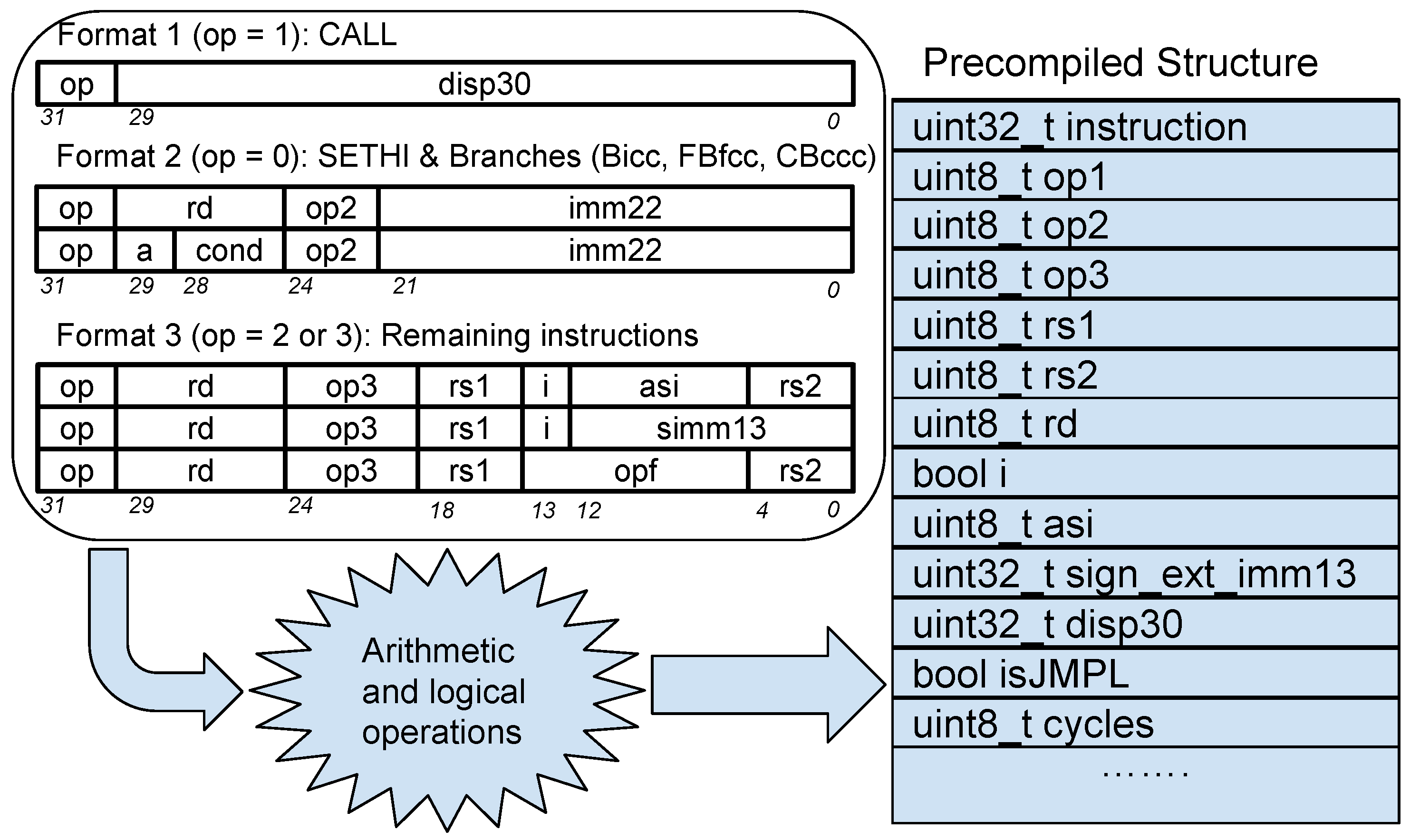
Figure 1. Precompiled instruction structure generation.
Electronics 10 01179 g001
Figure 2. LLVM coroutines orchestrator loop.
Electronics 10 01179 g002
Figure 3. Use case description: real (left) vs. simulated (right) execution platforms.
Electronics 10 01179 g003
Figure 4. hlMulticore interpartitions ARINC653 channels use case.
Electronics 10 01179 g004
Figure 5. Startup sequence.
Electronics 10 01179 g005
Figure 6. Buffer pool selection.
Electronics 10 01179 g006
Table 1. Thread and LLVM coroutines approaches performance results.
Thread ApproachLLVM First ExecutionLLVM with Cached Coroutines
smpschededf01 (single-core)0.57 MIPS2.745 MIPS5.052 MIPS
smpmigration01 (dual-core)0.791 MIPS4.261 MIPS4.862 MIPS
smpatomic01 (quad-core)0.804 MIPS6.263 MIPS6.691 MIPS
smpaffinity01 (quad-core)1.303 MIPS1.179 MIPS9.457 MIPS
ARINC653 use case (quad-core)0.576 MIPS0.062 MIPS4.31 MIPS
Table 2. Faulty configurations.
k123456789101112Total
Faulty configurations1266220495792924792495220661214095
Publisher’s Note: MDPI stays neutral with regard to jurisdictional claims in published maps and institutional affiliations.