Article

A One-Step Leapfrog ADI Procedure with Improved Absorption for Fine Geometric Details

1
School of Electronic and Information Engineering, Beihang University, Beijing 100191, China
2
Beijing Institute of Astronautical Systems Engineering, Beijing 100076, China
3
School of Electronic & Information Engineering, Nanjing University of Information Science and Technology, Nanjing 210096, China
4
Faculty of Textile Science and Technology, Shinshu University, 3-15-1 Tokida, Ueda-shi 386-8567, Japan
5
Institute of Carbon Science and Technology, Shinshu University, 4-17-1 Wakasato, Nagano 380-8553, Japan
*
Authors to whom correspondence should be addressed.
Electronics 2021, 10(10), 1135; https://doi.org/10.3390/electronics10101135
Submission received: 5 April 2021 / Revised: 4 May 2021 / Accepted: 7 May 2021 / Published: 11 May 2021
(This article belongs to the Section Computer Science & Engineering)

Abstract

:
Based on the alternating direction implicit (ADI) procedure, leapfrog formulation, and a higher order PML scheme, we propose an unconditionally stable perfectly matched layer (PML) algorithm with improved absorption to treat open regions in a finite computational domain with improved overall performance. The proposed algorithm performed well compared to other algorithms during simulations. We further demonstrated the proposed scheme’s effectiveness using numerical examples. We found that the proposed scheme had enhanced effectiveness and improved the absorption during the whole simulation. Furthermore, it was able to break the stability condition, proving that it is an unconditionally stable scheme.

1. Introduction

Full-wave simulation methods have become popular for use with multi-physics-related problems, especially in electromagnetic fields. The finite-difference time-domain (FDTD) algorithm is the most powerful and prevalent among full-wave simulation methods [1]. The original FDTD algorithm was a time-explicit algorithm with severely limited stability. According to the Courant–Friedrich–Levy (CFL) condition, the relationship between the mesh size and time step must be established. However, meeting this condition results in an unacceptable delay during the simulation of fine geometric details [2]. This phenomenon restricts the FDTD algorithm’s applications. In order to alleviate such conditions and improve efficiency at the same time, unconditionally stable algorithms are carried out. Among them, the alternating direction implicit (ADI) procedure, which calculates Maxwell’s equation in two sub-steps, has attracted considerable attention [3,4]. To enhance both efficiency and accuracy, a one-step leapfrog formulation was introduced to avoid the calculation of sub-steps [5], and it has been demonstrated that the leapfrog ADI procedure can obtain better performance [6].
The boundary condition should terminate the lattice at boundaries in full-wave simulation methods to simulate the infinite domain extension. The absorbing boundary condition is usually to absorb outgoing waves [2]. Among various absorbing boundary conditions, the perfectly matched layer (PML) has been widely applied in many circumstances [7]. The unsplit-field stretched coordinate PML (SC-PML) was proposed to simplify formulation at corners and edges [8]. The complex frequency-shifted (CFS) PML was proposed to reduce low-frequency evanescent waves and late-time reflections [9], both of which are inefficient at low-frequency propagation waves [10]. The higher order concept was introduced not only to alleviate such conditions but also to enhance absorption [11]. There is an increment of auxiliary variables and coefficients in the higher order concept [12,13]. The unconditionally stable scheme is one of the most powerful ways known to improve calculation efficiency [14].
Until now, PML boundary conditions have been developed with an ADI procedure and its promoted implementations. The formulation based on the CFS-PML scheme with an ADI procedure was first developed [15,16,17], and to improve its accuracy, the convolutional PML was incorporated with the leapfrog ADI procedure. However, it was demonstrated that the CFS-PML schemes are inefficient at a low frequency, so the higher order ADI-PML was introduced [18]. As the original ADI procedure splits the entire computation into several sub-steps, an alternative method should be further investigated.
Here, leapfrog higher order ADI-PML (LADI-HO-PML) is introduced for the termination of unbounded lattices. By incorporating a one-step formulation and higher order PML scheme, we demonstrate the improvement in performance numerically. Compared with ADI-HO-PML, the proposed scheme shows advantages over it in terms of accuracy, efficiency, and absorption. Such conclusions are demonstrated in the following section.

2. Formulation

In higher order PML regions, the Maxwell’s equations can be given in matrix form as
j ω ε 0 E = ( A B ) H
j ω μ 0 H = ( B A ) E
where E = [ E x , E y , E z ] T , H = [ H x , H y , H z ] T , and
A = [ 0 0 y S y 1 z S z 1 0 0 0 x S x 1 0 ] ,   B = [ 0 z S z 1 0 0 0 x S x 1 y S y 1 0 0 ] .
where E η and H η are electric and magnetic components, respectively, and η is the calculation of the partial derivative. S η ,   η = x , y , z are higher order stretched coordinate variables with a CFS factor, defined as
S η = ( κ η 1 + σ η 1 α η 1 + j ω ε 0 ) ( κ η 2 + σ η 2 α η 2 + j ω ε 0 )
where α η n ,   n = 1 , 2 absorb evanescent waves, and κ η n and σ η n reduce wave reflections [10]. The value of them can be chosen as follows: (1) κ η n 1 is a positive real, and (2) α η n and σ η n are real numbers. By employing the partial fraction expansion to the stretched coordinate variables, S η 1 is given as
S η 1 = k η ( j ω + a η 1 ) ( j ω + a η 2 ) ( j ω + b η 1 ) ( j ω + b η 2 )
where the coefficients are k η = 1 / ( κ η 1 κ η 2 ) , a η n = α η n / ε 0 , b η n = a η n + σ η n / ( ε 0 κ η n ) . By substituting (3) into Equation (1a,b) and introducing the auxiliary variables into the time domain, we have, for example,
t G ( η + 1 ) η 1 + b η 1 G ( η + 1 ) η 1 = k η η E ( η 1 )
t G ( η + 1 ) η 2 + b η 2 G ( η + 1 ) η 2 = t G ( η + 1 ) η 1 + b η 2 G ( η + 1 ) η 1
where ( η 1 ) ,   η ,   ( η + 1 ) satisfy the cyclic shift property; for example, η = x , while ( η 1 ) = y and ( η + 1 ) = z . F η and G η are both auxiliary variables which have similar forms. Thus, G η was chosen as an example. They can be obtained according to a similar procedure. By substituting auxiliary variables into the results, the equation can be given according to the ADI procedure in the FDTD domain as follows:
E n + 1 / 2 = E n + C e 1 F n + 1 / 2 + D e 1 H n + 1 / 2 C e 2 F n D e 2 H n
H n + 1 / 2 = H n + C h 1 G n + 1 / 2 + D h 1 E n + 1 / 2 C h 2 G n D e 2 E n
E n + 1 = E n + 1 / 2 + C e 1 F n + 1 + D e 1 H n + 1 C e 2 F n + 1 / 2 D e 2 H n + 1 / 2
H n + 1 = H n + 1 / 2 + C h 1 G n + 1 + D h 1 E n + 1 C h 2 G n + 1 / 2 D h 2 E n + 1 / 2
and F = [ F x ; F y ; F z ] T and F η = [ F η ( η + 1 ) 1 , F η ( η + 1 ) 2 , F η ( η 1 ) 1 , F η ( η 1 ) 2 ] T . The other coefficient matrices were as follows:
C e 1 = [ p 1 e y p 2 e y 0 0 0 0 p 1 e z p 2 e z p 1 e x p 2 e x 0 0 ] ,   C e 2 = [ 0 0 p 1 e z p 2 e z p 1 e x p 2 e x 0 0 0 0 p 1 e y p 2 e y ] , D e 1 = [ 0 0 p 3 y δ y p 3 z δ z 0 0 0 p 3 x δ x 0 ] ,   D e 2 = [ 0 p 3 z δ z 0 0 0 p 3 x δ x p 3 y δ y 0 0 ] .
The other components can be obtained in multiple ways. The coefficients can be obtained as the forms p 1 e η = 2 ( a η 1 b η 2 ) / ( Δ t ε 0 ) , p 2 e η = 2 ( a η 2 b η 1 ) / ( Δ t ε 0 ) , and p 3 e η = 2 k η / ( Δ t ε 0 ) . The operator δ η is the first order finite-difference form that discretizes the components in the space domain [19]; for example,
δ x H y n + 1 / 2 = ( H y | i + 1 / 2 , j , k + 1 / 2 n + 1 / 2 H y | i 1 / 2 , j , k + 1 / 2 n + 1 / 2 ) / Δ x
By substituting Equation (5b) into Equation (5a) to eliminate H y n + 1 / 2 and Equation (5d) into Equation (5c) by changing the nth time step to the (n − 1)th step, the following is obtained:
E n + 1 / 2 = E n + C e 1 F n + 1 / 2 + D e 1 H n + C h 1 D e 1 G n + 1 / 2 + D h 1 D e 1 E n + 1 / 2 C h 2 D e 1 G n D e 2 D e 1 E n C e 2 F n D e 2 H n
E n = E n + C e 1 F n 1 / 2 + D e 1 H n C e 2 F n D e 2 H n + C h 2 D e 1 G n + D e 1 D e 2 E n C h 2 D e 2 G n 1 / 2 D h 2 D e 2 E n 1 / 2
By combining Equation (7a) and Equation (7b) into a single equation, after some manipulation, it can be given as
( I D h 1 D e 1 ) E n + 1 / 2 = ( I D h 2 D e 2 ) E n 1 / 2 + 2 D e 1 H n 2 D e 2 H n + 2 C e 1 F n 2 C e 2 F n
Following a similar step to that shown by the electric components as Equation (8a), the updated equation of magnetic component can be obtained by
( I D e 1 D h 1 ) H n + 1 = ( I D e 2 D e 2 ) H n + 2 D h 1 E n + 1 / 2 2 D h 2 E n + 1 / 2 + 2 C h 1 G n + 1 / 2 2 C h 2 G n + 1 / 2
Due to the existence of numerous components, E z component was chosen as an example in an expanded equation form. According to Equation (7a) and Equation (7b), one obtains
E z n + 1 / 2 = E z n + p 1 e x F z x 1 n + 1 / 2 + p 2 e x F z x 2 n + 1 / 2 p 1 e y F z y 1 n p 2 e y F z y 2 n p 3 e y δ y H x n + p 3 e x δ x H y n + p 1 h x p 3 e x δ x G y x 1 n + 1 / 2 + p 2 h x p 3 e x δ x G y x 2 n + 1 / 2 + p 3 h x p 3 e x δ x δ x E z n + 1 / 2 p 1 h z p 3 e x δ x G y z 1 n p 2 h z p 3 e x δ x G y z 2 n p 3 h z p 3 e x δ x δ z E x n
E z n = E z n 1 / 2 + p 1 e x F z x 1 n 1 / 2 + p 2 e x F z x 2 n 1 / 2 p 1 e y F z y 1 n p 2 e y F z y 2 n p 3 e y δ y H x n + p 3 e x δ x H y n p 3 h x p 3 e x δ x δ x E z n 1 / 2 + p 2 h z p 3 e x δ x G y z 2 n + p 3 h z p 3 e x δ x δ z E x n p 1 h z p 3 e x δ x G y z 1 n p 2 h z p 3 e x δ x G y z 2 n p 3 h z p 3 e x δ x δ z E x n
By adding Equation (9a) and Equation (9b), the updated form can be obtained as
( 1 p 3 h x p 3 e x δ 2 x ) E z n + 1 / 2 = ( 1 p 3 h x p 3 e x δ 2 x ) E z n 1 / 2 + 2 p 1 e x F z x 1 n + 2 p 2 e x F z x 2 n 2 p 1 e y F z y 1 n 2 p 2 e y F z y 2 n 2 p 3 e y δ y H x n + 2 p 3 e x δ x H y n
The auxiliary variables are given as
G z η 1 n + 1 / 2 = p 4 η G z η 1 n 1 / 2 + p 5 η δ η E η ˜ n + 1 / 2
G z η 2 n + 1 / 2 = p 6 η G z η 2 n 1 / 2 + p 7 η G z η 1 n + 1 / 2 p 8 η G z η 1 n 1 / 2
where p 4 η = ( 4 b η 1 Δ t ) / ( 4 + b η 1 Δ t ) , p 5 η = 4 Δ t k η / ( 4 + b η 1 Δ t ) , p 6 η = ( 2 b η 2 Δ t ) / ( 2 + b η 2 Δ t ) , p 7 η = ( 2 + a η 2 Δ t ) / ( 2 + b η 1 Δ t ) , and p 8 η = ( 2 a η 2 Δ t ) / ( 2 + b η 1 Δ t ) . To clarify the demonstration of equations, Equations (10) and (11) can be converted into mathematical versions; for example, one obtains
E z , ( i , j , k + 1 / 2 ) n + 1 / 2 p 3 h x ( i ) p 3 e x ( i ) E z , ( i + 1 , j , k + 1 / 2 ) n + 1 / 2 p 3 h x ( i ) p 3 e x ( i ) E z , ( i , j , k + 1 / 2 ) n + 1 / 2 = E z , ( i + 1 , j , k + 1 / 2 ) n 1 / 2 p 3 h x ( i ) p 3 e x ( i ) E z , ( i + 1 , j , k + 1 / 2 ) n 1 / 2 p 3 h x ( i ) p 3 e x ( i ) E z , ( i , j , k + 1 / 2 ) n 1 / 2 + + 2 p 1 e x ( i ) F z x 1 , ( i , j , k + 1 / 2 ) n + 2 p 2 e x ( i ) F z x 2 , ( i , j , k + 1 / 2 ) n 2 p 1 e y ( j ) F z y 1 , ( i , j , k + 1 / 2 ) n 2 p 2 e y ( j ) F z y 2 , ( i , j , k + 1 / 2 ) n 2 p 3 e y ( j ) ( H x , ( i , j + 1 / 2 , k + 1 / 2 ) n H x , ( i , j 1 / 2 , k + 1 / 2 ) n ) / Δ y + 2 p 3 e x ( i ) ( H y , ( i + 1 / 2 , j , k + 1 / 2 ) n H y , ( i 1 / 2 , j , k + 1 / 2 ) n ) / Δ x
G z x 1 , ( i + 1 / 2 , j + 1 / 2 , k ) n + 1 / 2 = p 4 x ( i ) G z x 1 , ( i + 1 / 2 , j + 1 / 2 , k ) n 1 / 2 + p 5 x ( i ) ( E y , ( i + 1 , j + 1 / 2 , k ) n + 1 / 2 E y , ( i , j + 1 / 2 , k ) n + 1 / 2 ) / Δ x
G z x 2 , ( i + 1 / 2 , j + 1 / 2 , k ) n + 1 / 2 = p 6 x ( i ) G z x 2 , ( i + 1 / 2 , j + 1 / 2 , k ) n 1 / 2 + p 7 x ( i ) G z x 1 , ( i + 1 / 2 , j + 1 / 2 , k ) n + 1 / 2 p 8 x ( i ) G z x 1 , ( i + 1 / 2 , j + 1 / 2 , k ) n 1 / 2
where the operator δ 2 x with the term E z n + 1 / 2 forms the tri-diagonal matrix at the left side of the equation. The specific details can be further demonstrated through (12a). Compared with the sparse matrix, the calculation of a tri-diagonal matrix is much more efficient and can be directly solved by the Thomas algorithm [19].
A flow chart of the entire simulation is shown in Figure 1. It can be seen that the electric and magnetic components, as well as the auxiliary variables, are located in the middle, and integer time steps can be updated through a one-step procedure. The efficiency was compared with other typical algorithms, including leapfrog ADI with CPML, LADI-PML [17], ADI based on higher-order PML, and ADI-HO-PML (Table 1) [18]. The comparison can be made in a number of ways using addition/subtraction (A/S) and multiplication/division (M/D) operators in implicit (I) and explicit (E) equations, matrices, and using totals.
It is shown in Table 1 that the number of M/D and A/S with I and E equations is significantly higher when using ADI-HO-PML. In addition, the total number of operators was at least 54 higher when using ADI-HO-PML. Although each algorithm calculates six matrices in total, a decreased total number of operators results in an improvement in overall efficiency. When comparing the other algorithms with LADI-PML, by introducing several external auxiliary variables, the total number of operators increases, reducing the efficiency. However, this procedure results in an improvement in absorption in the time domain and enhanced performance, especially at low frequencies.

3. Numerical Simulation and Results

The effectiveness of algorithms can be illustrated by addressing wave radiation and propagation problems. For comparison, FDTD-PML [9], LADI-PML [13], HO-PML [13], and ADI-HO-PML were selected. In addition, LADI-PML with 20 grids was selected (LADI-PML Double). The other PMLs occupied 10 grids. The proposed scheme was also compared with the PML schemes which are used in commercial software, including the uniaxial PML (FDTD-UPML) in Ansys and convolutional PML (FDTD-CPML) in CST Studio [20,21]. Different problems were considered, including the wave radiation problem of a metamaterial structure and the wave transmission problem of an integrated circuit. Various algorithms were implemented using a personal computer with Intel Core i7-8700k, 3.20 GHz, and 128 GB (DDR4, 2666 MHz). The algorithms were implemented in Windows 10 using the C++ programming language and visual studio 2019. One of the outstanding advantages of the C++ programming language is that it is easier to develop with a graphics processing unit (GPU), which can further improve performance, especially in terms of efficiency [22].

3.1. Wave Radiation Problem in a Metamaterial Structure

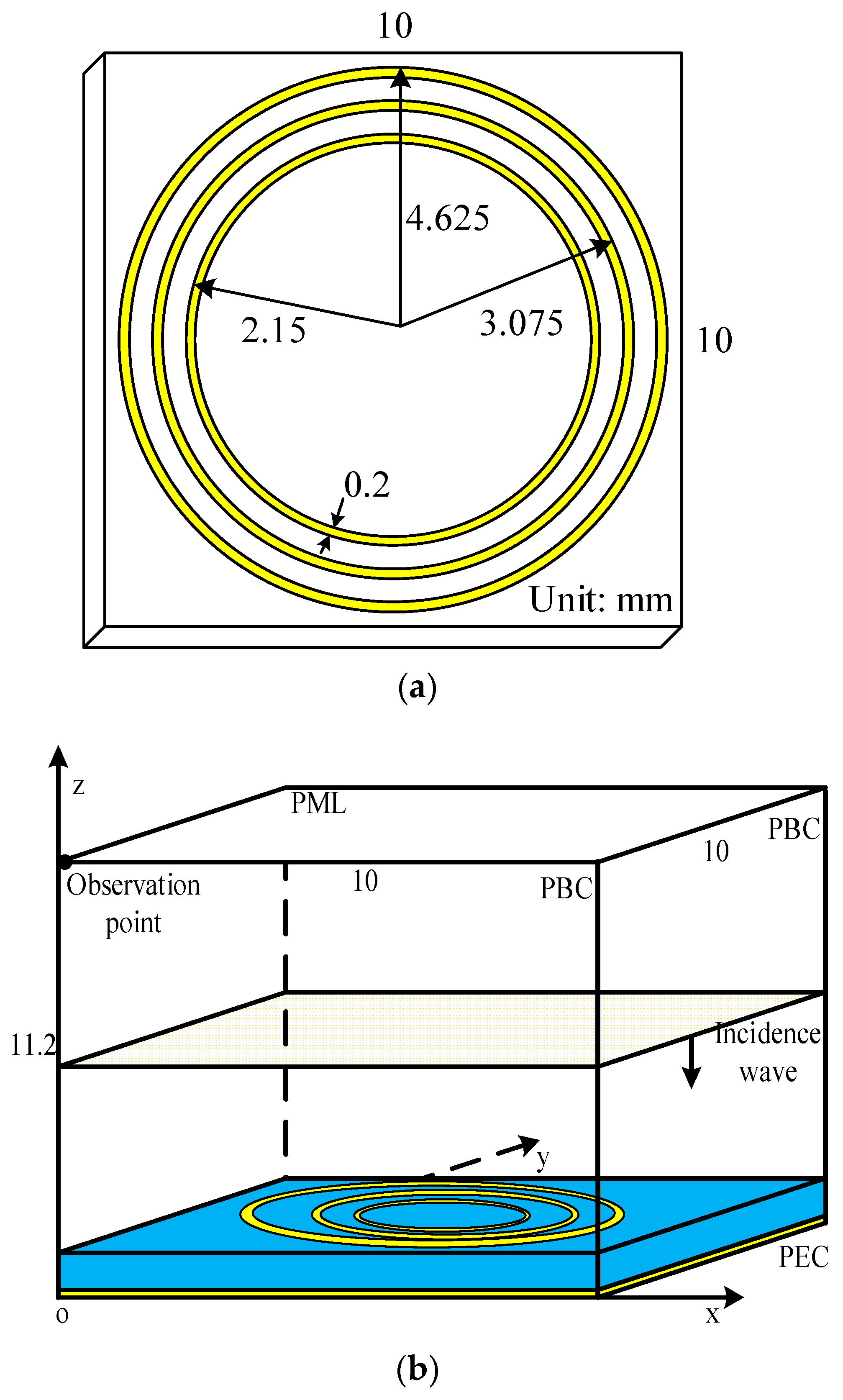
An ultra-thin polarization-independent metamaterial microwave absorber composed of three concentric closed ring resonators (CRRs) was used for the simulation of the wave radiation problem [23]. This structure can be regarded as a periodic metamaterial because it can absorb waves at a particular frequency. The artificial phenomenon can be controlled by changing the size of the unit structure [24,25]. Figure 2 shows a single unit inside a periodical metamaterial structure and its detail parameters.
Figure 2a shows the top view of the unit cell in the periodical metamaterial. At the bottom of the substrate, there was a PEC layer with dimensions of 10 mm × 10 mm × 0.1 mm. At the middle in the z-direction, an FR-4 substrate with dimensions of 10 mm × 10 mm × 1 mm had an electric parameter of ε r = 4.3 . A perfect electronic conductor (PEC) was used as the metal of CRRs in the simulation. The outer radii of the CRRs were 4.625 mm, 3.075 mm, and 2.15 mm. The CRRs have a width and thickness of 0.2 mm and 0.1 mm, respectively. In order to maintain the calculation accuracy and maintain efficiency, fine mesh sizes were employed in this numerical example. Applying the conventional FDTD directly into this structure resulted in an excessively long simulation duration due to the CFL limit. Thus, such an example is suitable for unconditionally stable algorithms.
In unconditionally stable algorithms, the mesh size can be selected according to the accuracy of calculation rather than the CFL condition. In Figure 2b, the entire computational domain has dimensions of 10 mm × 10 mm × 11.2 mm, which can be discretized as 400 Δ x × 400 Δ y × 448 Δ z by the FDTD lattice. The uniform mesh size in each direction was chosen as Δ x = Δ y = Δ z = Δ = 0.025 mm. A differential Gaussian pulse with a maximum frequency of 20 GHz incidents the top of the metamaterial structure. The source, which was located at the vertical mid-point, propagated along the negative side of the z-axis. At the boundaries of the x- and y-axes, the periodic boundary condition (PBC) was employed to simulate the periodic metamaterial structure. At the top of the computational domain, the PML region was employed to reduce wave reflections and absorb waves. It has been reported that the corner shows the worst performance compared with the edge and center of the PML regions [26]. Thus, to evaluate absorption in the worst-case scenario, the observation point was located at the top corner. Inside PML regions, the parameters were chosen to obtain the best absorption performance both in the time domain and frequency domain. The parameters of higher order PML algorithms were κ 1 = 75 , α 1 = 1.4 , m 1 = 3 , σ 1 max = 0.7 σ 1 o p t , κ 2 = 2 , α 1 = 0.03 , m 2 = 1 and σ 2 max = 0.01 σ 2 o p t , where
σ n o p t = ( m η n + 1 ) / ( 150 π Δ x )
The parameters for the CFS-PML based PML algorithms were κ η = 100 , α η = 2.2 , m η = 2 and σ η max = 1.0 σ η o p t . The maximum time step which satisfies the CFL condition can be calculated by Δ t max F D T D = 4.81 ps. The CFL number (CFLN) is defined as C F L N = Δ t / Δ t max F D T D , where Δ t is the time step employed in unconditionally stable algorithms. Absorption performance can be evaluated by the relative reflection error in the time domain [27], which can be defined as follows:
R d B ( t ) = 20 log 10 | ( E z t ( t ) E z r ( t ) ) / max { E z r ( t ) } |
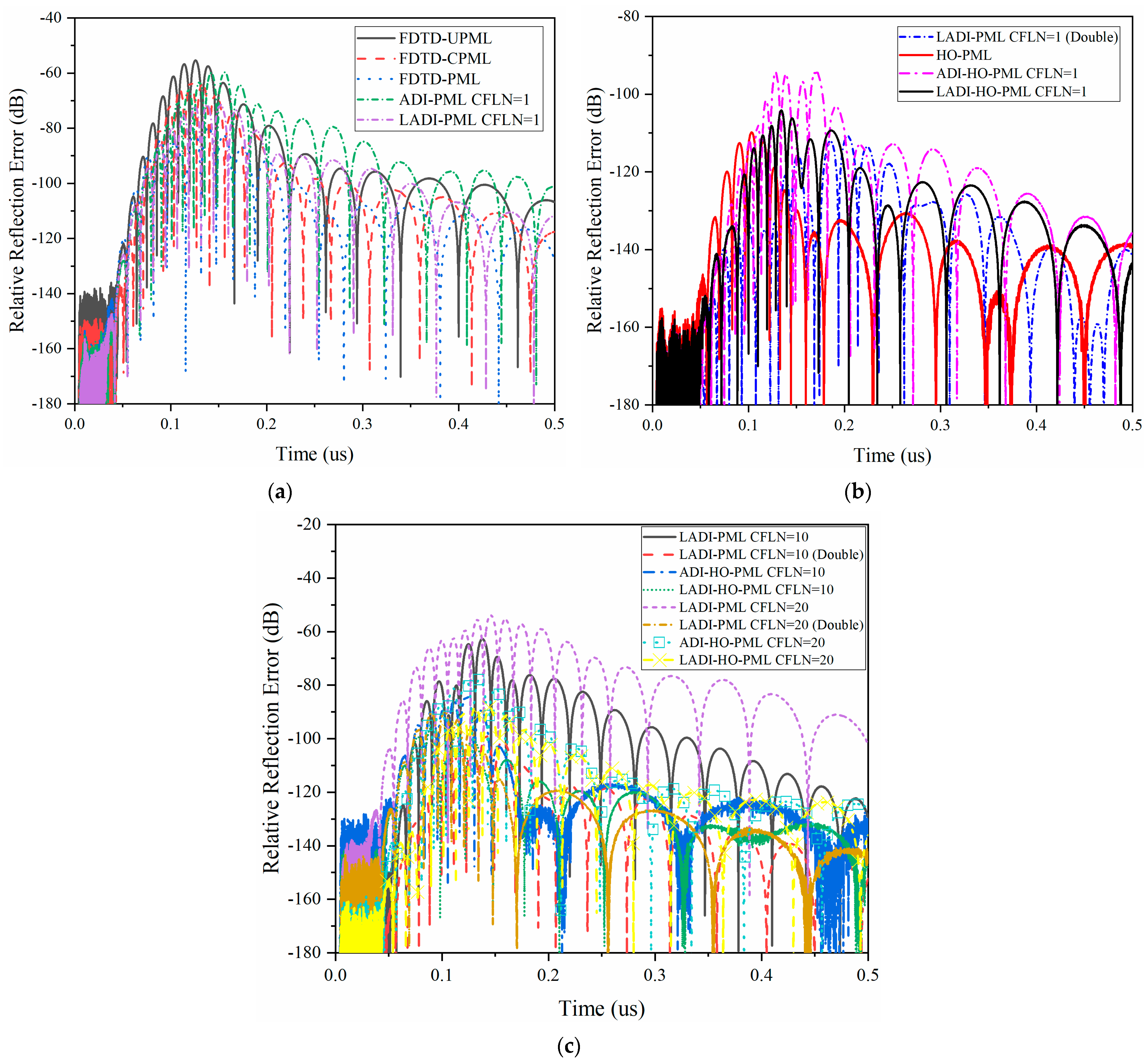
where E z t ( t ) represents the test solution, which can be observed directly at the observation point. E z r ( t ) is the reference solution that can be obtained by the enlargement domain and thicker PML regions. During the calculation of the reference solution, the reflection waves can be ignored due to the enlargement domain and thicker PML regions. The entire simulation takes 0.7881 ns (163,840 steps with CFLN = 1). For clearance, 0.5 ns is shown in the demonstration of relative reflection error. Figure 3 shows the relative reflection error in the time domain obtained by different PMLs and CFLNs.
The absorption can be reflected by maximum reflection error and late-time reflections in the time domain. As shown in Figure 3a, FDTD-CPML and FDTD-UPML had the worst performance using both measures. Although the maximum value of the relative reflection error obtained by different PML algorithms was lower than −40 dB, which can be used for practical engineering, the accuracy of the calculation can still be improved [28]. This indicates that the scheme proposed in this study is better compared with the PML schemes used in the commercial software. Compared with the ADI procedure, the LADI procedure can significantly improve absorption due to the enhanced calculation accuracy and decreased numerical dispersion [29]. From Figure 3b, it can be seen that the absorption can be improved through the thicker PML regions and using the higher order concept. Nevertheless, it can be concluded that absorption can be further improved.
Furthermore, as can be observed from Figure 3b, the LADI-PML with double grids and HO-PML had a similar performance which was better than the other algorithms. Although the proposed scheme shows inferior performance compared with these two algorithms, it still shows enhanced performance compared with ADI-HO, LADI-, FDTD-PMLs, FDTD-UML, and FDTD-CPML. This indicates that the proposed scheme is efficient in terms of absorption. As shown in Figure 3c, overall absorption decreased with the increment of CFLNs because numerical dispersion increases with CFLNs. A lower number of CFLNs had better performance; thus, overall performance with CFLN = 10 was higher than with CFLN = 20. It can be concluded from Figure 3 that absorption of higher order PML shows better performance over the entire simulation.
The calculation accuracy can be evaluated by the global error when CFLN = 1. The global error indicates the accuracy, which can be obtained by directly comparing the value of the waveform, defined as
R d B ( t ) = 20 log 10 | ( E z t ( t ) E z b ( t ) ) / max { E z b ( t ) } |
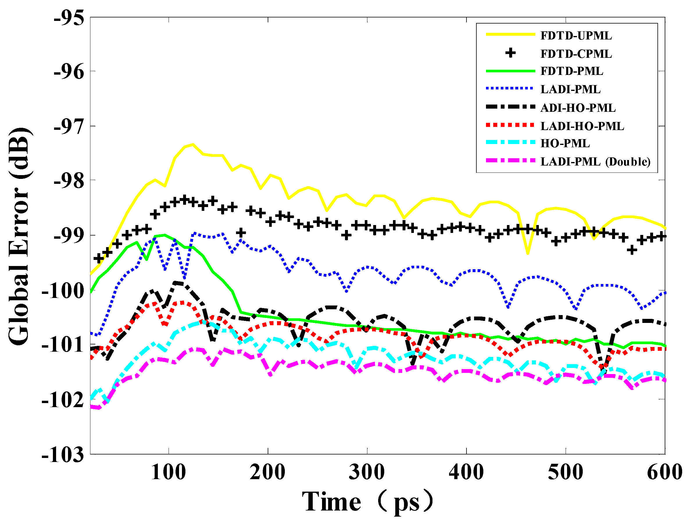
where E z b ( t ) is the basis solution for the comparison [30]. Here, the basis of the comparison was obtained by an enlarged vertical z-axis with dimensions of 400 Δ x × 400 Δ y × 1448 Δ z . During the calculation of the basis solution, the waveform at the observation point was close to the analytic solutions of Maxwell’s equations. Figure 4 shows the global error obtained by different PML algorithms with CFLN = 1, which shows 600 ps to clarify the demonstration.
Through the comparison shown in Figure 4, it can be observed that LADI-PML with double grids showed the lowest global error and best accuracy. Meanwhile, the proposed scheme had inferior performance compared with HO and LADI-PML with double grids. However, compared with FDTD-UPML, FDTD-CPML, FDTD-, LADI- and ADI-HO-PMLs, the proposed scheme performed better. Most importantly, compared with FDTD-UPML and FDTD-CPML used by commercial software, the proposed scheme had better accuracy. Algorithms were also evaluated by their efficiency in terms of CFLN, MRRE, time, memory, and time reduction (Table 2). The time reduction represents the reduction in running duration, defined as
T i m e   R e d u c t i o n = ( T P M L _ a lg o r i t h m s T b _ a lg o r i t h m ) / T b _ a lg o r i t h m
where T P M L _ a lg o r i t h m s is the simulation duration of different PML algorithms and T b _ a lg o r i t h m is the simulation duration of the basis algorithm. Here, the FDTD-PML was selected as the basis for comparison. Table 2 shows that, although LADI-PML with double grids had the best performance, it needed more resources and longer duration compared with the other algorithms. This becomes unacceptable when simulating larger domains or much finer structures. Thus, although the enlargement of PML regions can obtain better performance, it consumes more resources than a higher order scheme. This indicates the efficiency of the higher order PML formulation. Compared with HO-PML and ADI-HO-PML, the proposed scheme can have significantly improved efficiency with larger CFLN values. For the proposed scheme, with CFLN = 10, it can attain higher efficiency than FDTD-CPML and FDTD-UPML.
The absorption can be assessed by the reflection coefficient in the frequency domain, expressed by the following formulation:
R d B ( f ) = 20 log 10 | F F T { E z t ( t ) E z r ( t ) } / F F T { E z r ( t ) } |
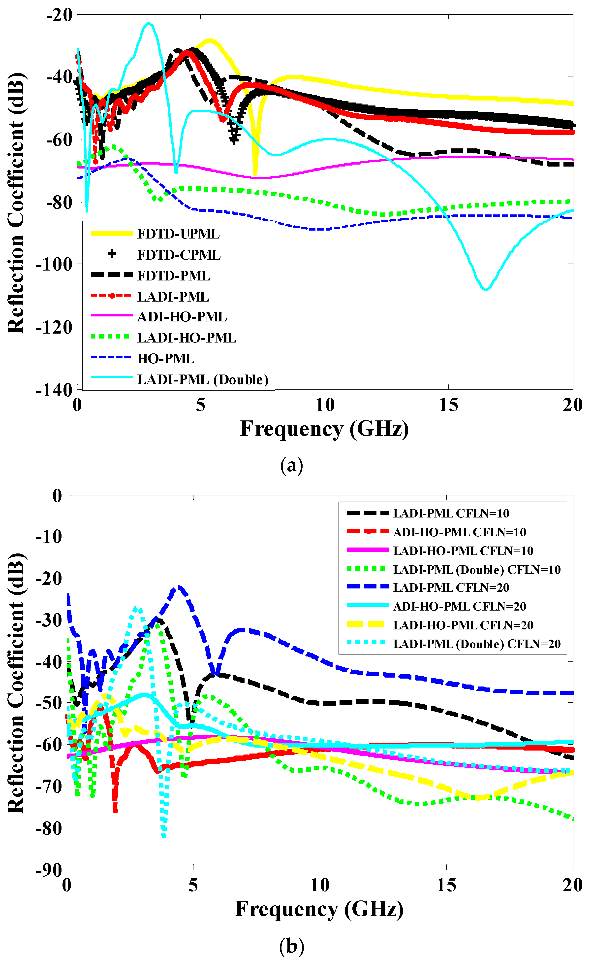
where the operator F F T { } is the Fourier transformation [31]. Figure 5 shows the reflection coefficient obtained by various algorithms and CFLNs.
As shown in Figure 5a, FDTD-PML, FDTD-UPML, and FDTD-CPML exhibited inferior performance compared with the grids with greater thickness and the higher order concept. Although they had accuracy values below −40 dB, the calculation accuracy, especially within the low-frequency band, still needs to be improved. While the LADI-PML with double grids could obtain better performance, the huge reflection of low-frequency waves was not absorbed, which leads to inaccuracy at low frequencies. Compared with the thicker grids, the higher order PML regions showed significant improvements not only at a low frequency but also for the entire simulation. This indicates the effectiveness of the proposed higher order PML algorithm. The reason for this was that the higher order PML absorbed low-frequency propagation waves resulting in the enhanced absorption in the low-frequency. However, it also enhanced absorption performance over the entire frequency band.
Figure 5b shows that the absorption decreased with the increment of CFLNs due to the enlargement of numerical dispersion. It can be observed that LAD-PML was close to −20 dB at some frequencies, which significantly affects the calculation accuracy. LADI-PML was unable to use larger CFLNs in this metamaterial structure. For ADI-HO-PML and ADI-PML with double grids, the reflection coefficient within these frequencies still needs to be improved. It can be concluded that the proposed scheme can maintain considerable absorption during the whole simulation.
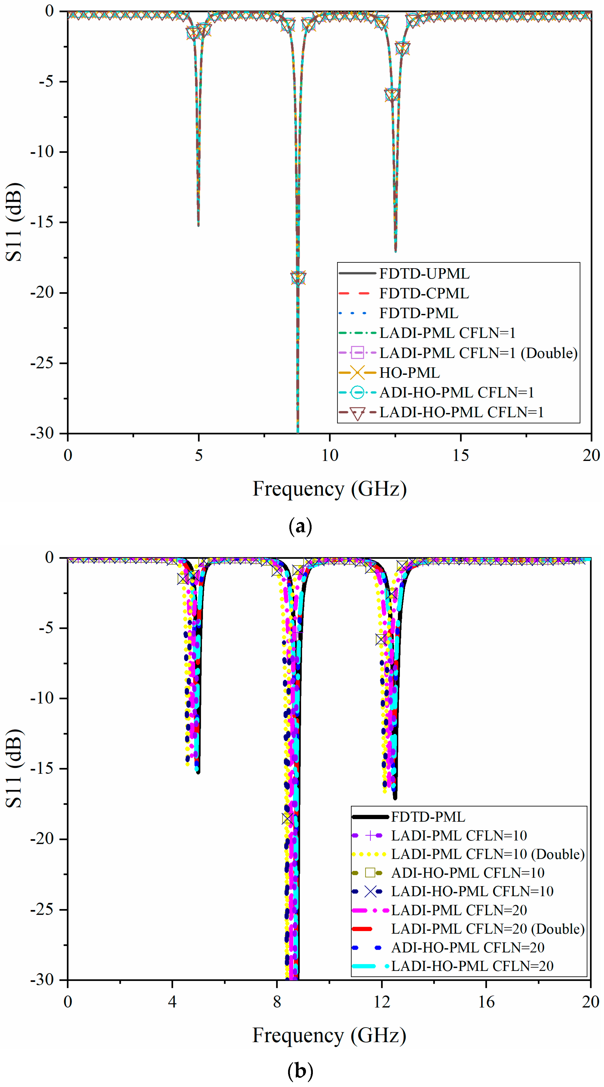
Periodic metamaterial shows its unique properties at differential frequencies. The accuracy of calculation and performance of metamaterial can be evaluated by the return loss or S11 parameter. Figure 6 shows the S11 in the frequency domain obtained by different PML algorithms and CFLNs. As shown in Figure 6a, S11 parameters with CFLN = 1 overlapped, indicating that these algorithms had the same accuracy at lower CFLNs. Figure 6b shows that the proposed scheme showed less change compared with ADI-HO-PML at CFLN = 10 and 20, which indicates that the proposed scheme had better absorption resulting in an improvement to the calculation accuracy.
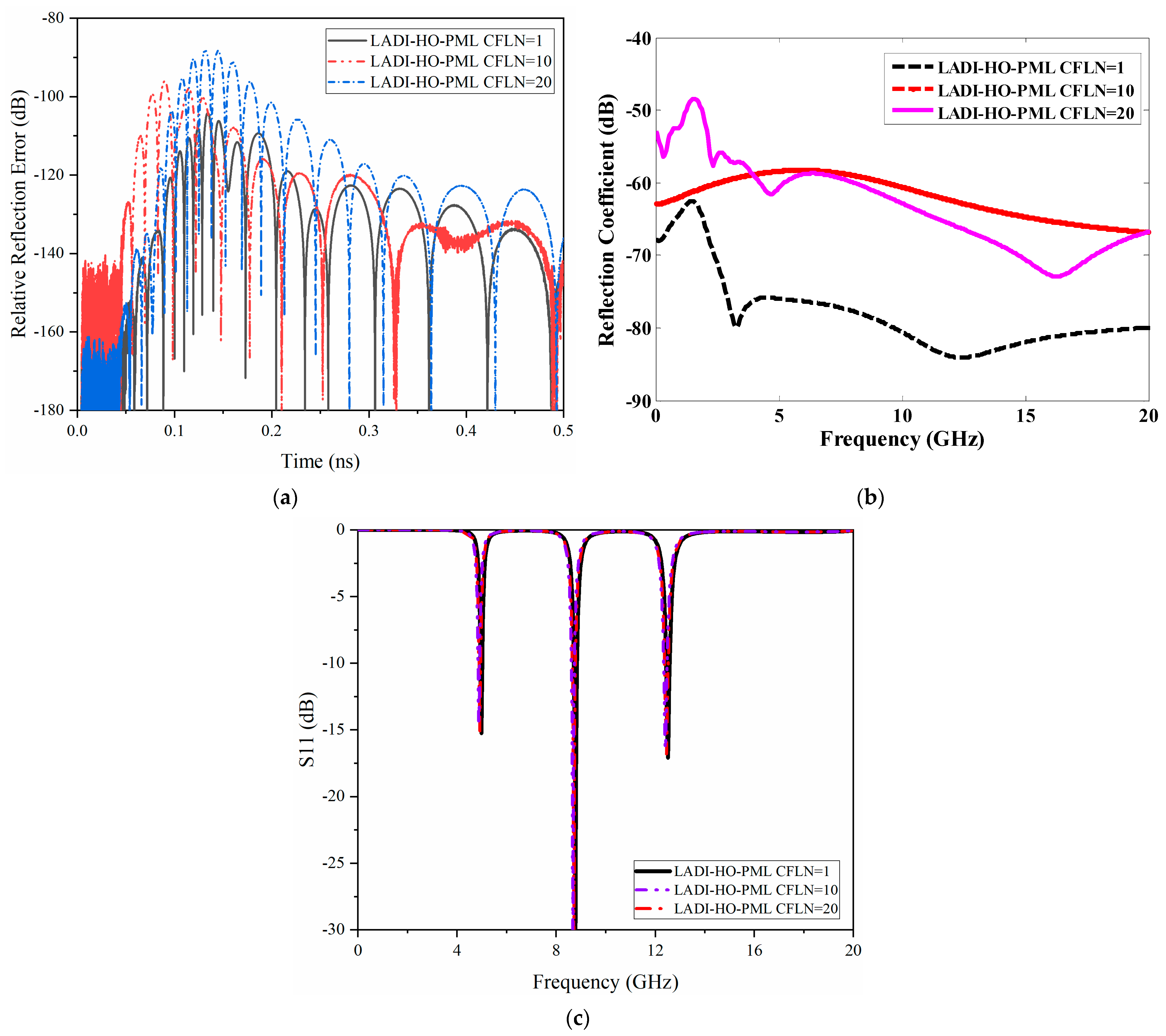
To further assess the performance of the proposed scheme at different CFLNs, we examined the relative reflection error, reflection coefficient, and return loss of algorithms (Figure 7). Although the performance of the proposed algorithm decreased with the increment of CFLNs due to the enlargement of numerical dispersion, it still maintained a relatively high level with CFLN = 20, indicating that the proposed scheme is efficient during the whole simulation.

3.2. Wave Propagation Problem—Very Large Scale Integration (VLSI) Interconnect Model

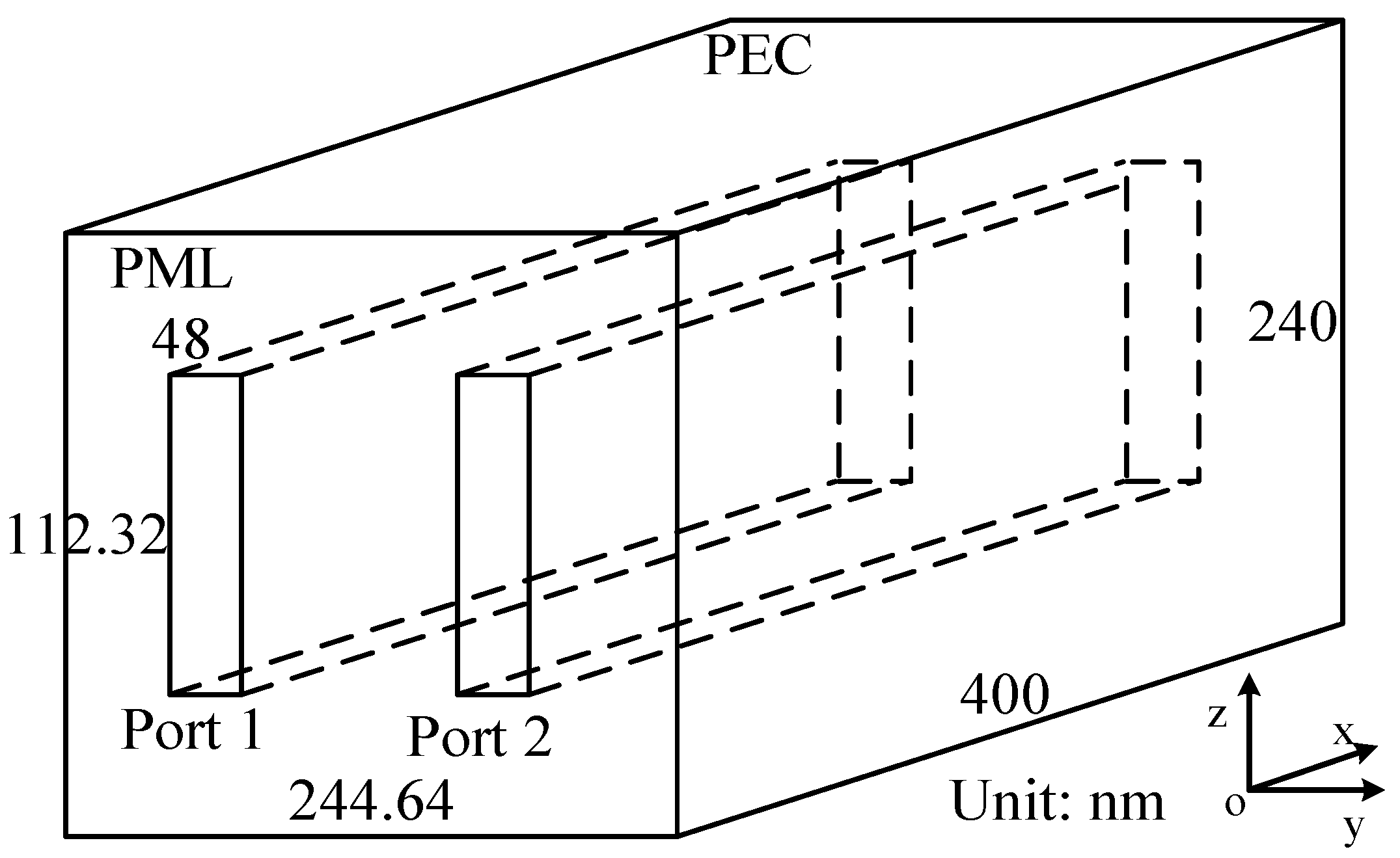
The VLSI structure had fine geometric details in all dimensions (Figure 8). Thus, a micron-scale mesh size must be employed for the accuracy simulation [32]. The VLSI interconnect model had dimensions of 400 × 240 × 244 . 64 nm in each direction. Each port with a size of 400 × 48 × 112 . 32 nm was composed of dielectric material with a parameter of ε r = 2.78 . The rest of the model had a dielectric parameter of ε r = 6.9 . The voltage source was at port 1 and traveled along the positive x-axis. The top and bottom boundaries were regarded as PEC for the ground conductor, while the others were terminated by PML regions for the accuracy calculation. The optimal parameters inside the PML regions were chosen. The parameters of higher order PML algorithms were κ 1 = 15 , α 1 = 2.7 , m 1 = 2 , σ 1 max = 2.6 σ 1 o p t , κ 2 = 10 , α 1 = 1.1 , m 2 = 4 and σ 2 max = 0.001 σ 2 o p t . The parameters for the CFS-PML based PML algorithms were κ η = 17 , α η = 1.9 , m η = 3 and σ η max = 2.9 σ η o p t .
Uniform mesh sizes were chosen as Δ x = Δ z = 1 nm and Δ y = 0.5 nm to maintain the calculation accuracy. The whole computational domain can be discretized as 400 Δ x × 488 Δ y × 240 Δ z in the FDTD computational domain. The time step which satisfied the CFL condition was obtained after 9.6 × 10 19 s. It can be observed that a small time step results in an extremely long simulation duration. This cannot be realized when employing conventional algorithms. The introduction of unconditionally stable algorithms can be regarded as an effective way to overcome this obstacle [32].
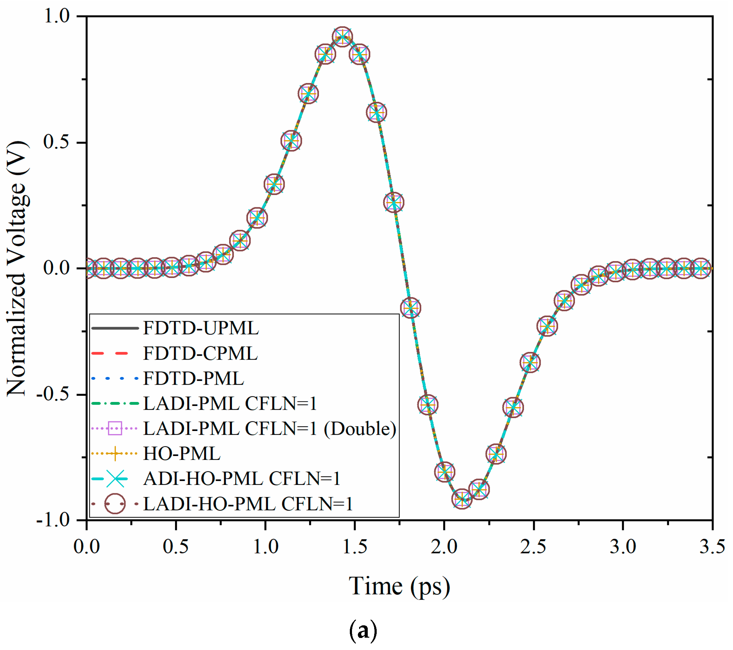
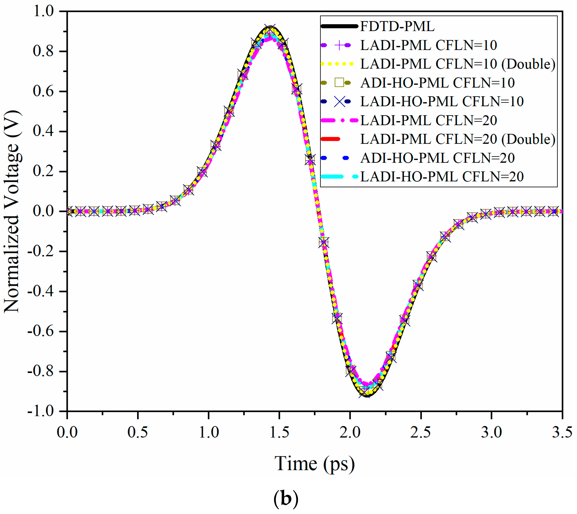
The absorption and accuracy of different PML algorithms can be illustrated by observing the waveform at port 2 (Figure 9).
Figure 9a shows that the waveforms obtained by different PML algorithms almost overlapped, indicating that they had a similar calculation accuracy. As can be observed from Figure 9b, the waveform showed some shifting with the increment of CFLNs, indicating the decrement of calculation accuracy. The reason is that the numerical dispersion increased with the increment of CFLNs, leading to the decrement of calculation accuracy. The LADI-PML with double grids had the best absorption and accuracy. While the proposed scheme was inferior, it performed better than FDTD-CPML and FDTD-UPML. By comparing different curves in Figure 9a,b, it can be observed that the absorption can be improved by employing the higher order concept and thicker grids. The effectiveness can be reflected by absorption as well as efficiency. Table 3 shows the effectiveness of the proposed scheme in terms of the CFLN, time, CPU time, and time reduction.

4. Conclusions

Based on a one-step leapfrog ADI procedure and higher order concept, an unconditionally stable scheme was proposed for open region problems with fine geometric details. A periodic metamaterial structure and VLSI model were used to demonstrate the performance of the proposed scheme. We found that the proposed scheme has advantages over the LADI procedure and HO-PML in terms of its considerable accuracy, improved absorption, and enhanced efficiency.

Author Contributions

P.W. formed the idea and wrote the manuscript; H.J. implemented the algorithms; H.Y. revised the manuscript and carried out experiments; Y.X. and T.N. revised the manuscript and provided comments. All of the authors approve the submission. All authors have read and agreed to the published version of the manuscript.

Funding

This paper was supported by the National Natural Science Foundation of China (Grant No. 61571022, 61971022, 61801376) and National Key Laboratory Foundation (HTKJ2019KL504013, 61424020305).

Data Availability Statement

The data used to support the findings of this study are available from the corresponding author upon request.

Conflicts of Interest

The authors declare no conflict of interest.

References

  1. Yee, K. Numerical solution of initial boundary value problems involving maxwell’s equations in isotropic media. IEEE Trans. Antennas Propag. 1966, 14, 302–307. [Google Scholar]
  2. Taflove, A.; Hagness, S.C. Computational Electrodynamics: The Finite-Difference Time-Domain Method, 3rd ed.; Artech House: Norwood, MA, USA, 2005. [Google Scholar]
  3. Namiki, T. 3-D ADI-FDTD method unconditionally stable time- domain algorithm for solving full vector Maxwell’s equations. IEEE Trans. Microw. Theory Tech. 2000, 48, 1743–1748. [Google Scholar] [CrossRef]
  4. Yang, S.-C.; Chen, Z.D.; Yu, Y.-Q.; Yin, W.-Y. The Unconditionally Stable One-Step Leapfrog ADI-FDTD Method and Its Comparisons with Other FDTD Methods. IEEE Microw. Wirel. Compon. Lett. 2011, 21, 640–642. [Google Scholar] [CrossRef]
  5. Yang, S.-C.; Chen, Z.; Yu, Y.; Yin, W.-Y. An Unconditionally Stable One-Step Arbitrary-Order Leapfrog ADI-FDTD Method and Its Numerical Properties. IEEE Trans. Antennas Propag. 2012, 60, 1995–2003. [Google Scholar] [CrossRef]
  6. Kong, Y.; Chu, Q.; Li, R. Efficient unconditionally stable one-step leapfrog ADI-FDTD method with low numerical dispersion. IET Microw. Antennas Propag. 2014, 8, 337–345. [Google Scholar] [CrossRef]
  7. Berenger, J.P. A perfectly matched layer for the absorption of electromagnetic waves. J. Comput. Phys. 1994, 114, 185–200. [Google Scholar] [CrossRef]
  8. Chew, W.C.; Weedon, W.H. A 3D perfectly matched medium from modified Maxwells equations with stretched coordinates. Microw. Opt. Technol. Lett. 1994, 7, 599–604. [Google Scholar] [CrossRef]
  9. Kuzuoglu, M.; Mittra, R. Frequency dependence of the constitutive parameters of causal perfectly matched anisotropic absorbers. IEEE Microw. Guid. Wave Lett. 1996, 6, 447–449. [Google Scholar] [CrossRef]
  10. Bérenger, J.-P. Perfectly Matched Layer (PML) for Computational Electromagnetics. Synth. Lect. Comput. Electromagn. 2007, 2, 1–117. [Google Scholar] [CrossRef] [Green Version]
  11. Wagner, C.L.; Young, J.L. FDTD Numerical Tests of the Convolutional? PML at Extremely Low Frequencies. IEEE Antennas Wirel. Propag. Lett. 2009, 8, 1398–1401. [Google Scholar] [CrossRef]
  12. Correia, D.; Jin, J.-M. Performance of regular PML, CFS-PML, and second-order PML for waveguide problems. Microw. Opt. Technol. Lett. 2006, 48, 2121–2126. [Google Scholar] [CrossRef]
  13. Feng, N.; Yue, Y.; Zhu, C.; Wan, L.; Liu, Q.H. Second-order PML: Optimal choice of nth-order PML for truncating FDTD domains. J. Comput. Phys. 2015, 285, 71–83. [Google Scholar] [CrossRef]
  14. Wei, X.-K.; Shao, W.; Shi, S.-B.; Cheng, Y.-F.; Wang, B.-Z. An Optimized Higher Order PML in Domain Decomposition WLP-FDTD Method for Time Reversal Analysis. IEEE Trans. Antennas Propag. 2016, 64, 4374–4383. [Google Scholar] [CrossRef]
  15. Hwang, J.-N.; Chen, F.-C. A Rigorous Stability Analysis of Instability in ADI-FDTD Method with PML Absorber. 2006 IEEE Antennas Propag. Soc. Int. Symp. 2006, 1739–1742. [Google Scholar] [CrossRef]
  16. Sun, S.-H.; Choi, C. Performance of the improved PML for the envelope ADI-FDTD method in two-dimensional domain. IEEE Microw. Wirel. Compon. Lett. 2005, 15, 820–822. [Google Scholar]
  17. Wang, X.-H.; Yin, W.-Y.; Yu, Y.-Q.; Chen, Z.; Wang, J.; Guo, Y. A Convolutional Perfect Matched Layer (CPML) for One-Step Leapfrog ADI-FDTD Method and Its Applications to EMC Problems. IEEE Trans. Electromagn. Compat. 2012, 54, 1066–1076. [Google Scholar] [CrossRef]
  18. Wu, P.Y.; Jiang, H.L.; Xie, Y.J.; Niu, L.Q. Three-Dimensional Higher Order PML Based on Alternating Direction Implicit Algorithm. IEEE Antennas Wirel. Propag. Lett. 2019, 18, 2592–2596. [Google Scholar] [CrossRef]
  19. Sauer, T. Numerical Analysis, 2nd ed.; Pearson Education: London, UK, 2012. [Google Scholar]
  20. Appannagarri, N.; Bardi, I.; Edlinger, R.; Manges, J.; Vogel, M.; Cendes, Z.; Hadden, J. Modeling phased array antennas in Ansoft HFSS. In Proceedings of the 2000 IEEE International Conference on Phased Array Systems and Technology (Cat. No.00TH8510), Dana Point, CA, USA, 21–25 May 2000; pp. 323–326. [Google Scholar]
  21. Shin, Y.-M.; Barnett, L.R.; Baig, A.; Luhmann, N.C.; Pasour, J.; Larsen, P. Numerical modeling analysis of 0.22 THz sheet beam TWT circuit. In Proceedings of the 2011 IEEE International Vacuum Electronics Conference (IVEC), Bangalore, India, 21–24 February 2011; pp. 139–140. [Google Scholar]
  22. Wu, P.Y.; Xie, Y.J.; Niu, L.Q.; Jiang, H.L. Hybrid domain multipactor prediction algorithm and its CUDA parallel implementation. J. Syst. Eng. Electron. 2020, 31, 1097–1104. [Google Scholar]
  23. Bhattacharyya, S.; Ghosh, S.; Srivastava, K.V. Equivalent circuit model of an ultra-thin polarization-independent triple band metamaterial absorber. AIP Adv. 2014, 4, 097127. [Google Scholar] [CrossRef] [Green Version]
  24. You, J.W.; Zhang, J.F.; Jiang, W.X.; Ma, H.F.; Cui, W.Z.; Cui, T.J. Accurate Analysis of Finite-Volume Lumped Elements in Metamaterial Absorber Design. IEEE Trans. Microw. Theory Tech. 2016, 64, 1966–1975. [Google Scholar] [CrossRef]
  25. Cui, T.J.; Smith, D.R.; Liu, R. Metamaterials; Springer: Berlin/Heidelberg, Germany, 2010. [Google Scholar]
  26. Niu, L.Q.; Xie, Y.J.; Jiang, H.L.; Wu, P. Exponential time differencing based efficient SC-PML for RCS simulation. J. Syst. Eng. Electron. 2020, 31, 703–711. [Google Scholar]
  27. Li, J.; Dai, J. Efficient implementation of the stretched co-ordinate perfectly matched layer based on the Z-transform method. IET Microw. Antennas Propag. 2007, 1, 645–650. [Google Scholar] [CrossRef]
  28. Li, J.; Wu, P.; Jiang, H. The implementation of unconditionally stable higher order PML based on the implicit CNAD-FDTD algorithm. J. Electromagn. Waves Appl. 2018, 33, 151–164. [Google Scholar] [CrossRef]
  29. Gan, T.H.; Tan, E.L. Analysis of the Divergence Properties for the Three-Dimensional Leapfrog ADI-FDTD Method. IEEE Trans. Antennas Propag. 2012, 60, 5801–5808. [Google Scholar] [CrossRef]
  30. Su, M.; Liu, P.-G. A global optimized parameter to reduce the numerical dispersion of the LOD-FDTD method. 2016 Asia-Pac. Int. Symp. Electromagn. Compat. 2016, 1, 742–744. [Google Scholar]
  31. Wang, S.; Teixeira, F. An efficient PML implementation for the ADI-FDTD method. IEEE Microw. Wirel. Compon. Lett. 2003, 13, 72–74. [Google Scholar] [CrossRef] [Green Version]
  32. Hong, W.; Sun, W.-K.; Zhu, Z.-H.; Ji, H.; Song, B.; Dai, W.-M. A novel dimension-reduction technique for the capacitance extraction of 3-D VLSI interconnects. IEEE Trans. Microw. Theory Tech. 1998, 46, 1037–1044. [Google Scholar] [CrossRef]
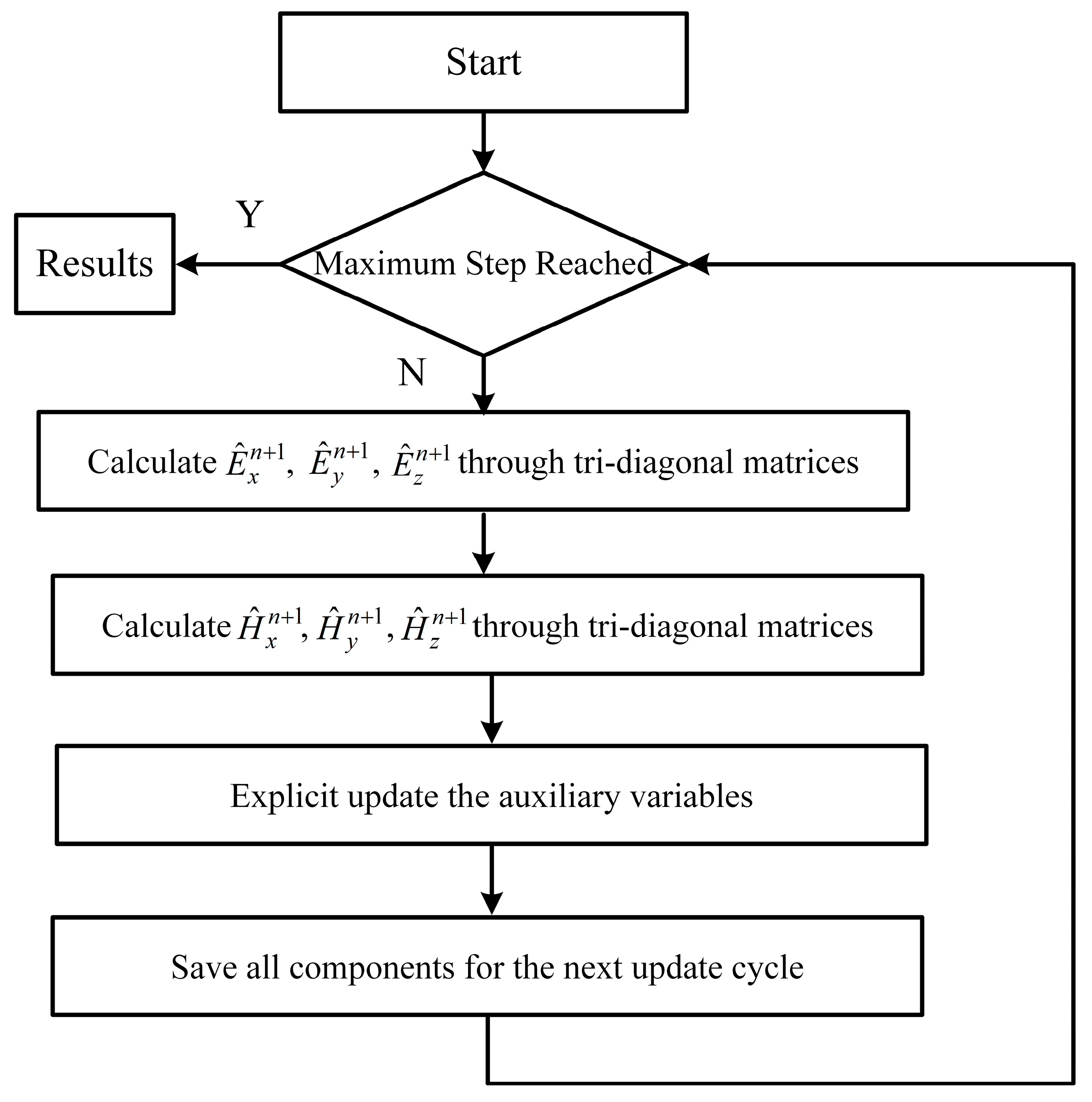
Figure 1. Flow chart of the entire LADI-HO-PML procedure.
Electronics 10 01135 g001
Figure 2. The single unit inside a periodic metamaterial structure and the detailed parameters of a unit cell (a) and inside the open region FDTD computational domain (b).
Electronics 10 01135 g002
Figure 3. The relative reflection error versus time obtained by (a) FDTD-UPML, FDTD-CPML, FDTD, and LADI-PMLs CFLN = 1; (b) LADI- Double, HO-, ADI-HO, and LADI-HO-PMLs CFLN = 1; and (c) LADI-, LADI- Double, HO, ADI-HO, and LADI-HO-PMLs CFLN = 10 and 20.
Electronics 10 01135 g003
Figure 4. The global error obtained by different PML algorithms when CFLN = 1.
Electronics 10 01135 g004
Figure 5. The reflection coefficient obtained by (a) FDTD-UPML, FDTD-CPML, FDTD, LADI, LADI Double, HO, ADI-HO, and LADI-HO-PMLs at CFLN = 1; (b) LADI, LADI- Double, HO, ADI-HO, and LADI-HO-PMLs at CFLN = 10 and CFLN = 20.
Electronics 10 01135 g005
Figure 6. S11 parameters versus frequency of metamaterial: (a) FDTD-UPML, FDTD-CPML, FDTD, LADI, LADI- Double, HO, ADI-HO-, and LADI-HO-PMLs at CFLN = 1; (b) LADI, LADI Double, HO, ADI-HO, and LADI-HO-PMLs at CFLN = 10 and CFLN = 20.
Electronics 10 01135 g006
Figure 7. Different parameters obtained by LADI-HO-PML with CFLN = 1, 10 and 20 (a) The relative reflection error in the time domain. (b) The reflection coefficient in the frequency domain (c) The S11 parameter of the periodically metamaterial structure in the frequency domain.
Electronics 10 01135 g007
Figure 8. The VLSI interconnect model.
Electronics 10 01135 g008
Figure 9. The normalized voltage obtained by (a) FDTD-UPML, FDTD-CPML, FDTD, LADI, LADI Double, HO, ADI-HO-, and LADI-HO-PMLs at CFLN = 1; and (b) LADI, LADI Double, HO, ADI-HO, and LADI-HO-PMLs at CFLN = 10 and CFLN = 20.
Electronics 10 01135 g009aElectronics 10 01135 g009b
Table 1. Comparison between matrices, M/D and A/S, in terms of I and E with different algorithms.
PML AlgorithmTri-Diagonal MatricesM/DA/STotal
IEIE
LADI-PML632281048124
ADI-HO-PML648662472210
LADI-HO-PML642361860156
Table 2. Comparison of algorithms in terms of CFLN, CPU time, memory, and reduction of different PML algorithms in a metamaterial model.
PML AlgorithmCFLNTime (min)Memory (GB)Reduction (%)MRRE (dB)
FDTD-PML149.22.2-−79.5
FDTD-UPML145.42.07.7−57.3
FDTD-CPML148.12.22.2−62.2
LADI-PML1396.83.3−706.5−71.3
LADI-PML1043.73.311.2−62.7
LADI-PML2017.23.354.5−53.8
LADI-PML (D)11077.35.1−2089.6−118.6
LADI-PML (D)10129.05.1−161.2−98.6
LADI-PML (D)2041.15.116.5−92.9
HO-PML1104.43.2−112.2−109.7
ADI-HO-PML1851.85.0−1631.3−95.9
ADI-HO-PML1090.25.0−83.3−83.8
ADI-HO-PML2038.25.022.4−77.9
LADI-HO-PML1749.64.7−1423.6−104.1
LADI-HO-PML1072.74.7−47.8−96.0
LADI-HO-PML2030.44.738.2−88.1
Table 3. Comparison of CFLN, CPU time, memory, and reduction of different PML algorithms in the VLSI structure.
PML AlgorithmCFLNTime (min)Memory (GB)Reduction (%)
FDTD-PML132.91.7-
FDTD-UPML130.81.56.4
FDTD-CPML131.61.74.0
LADI-PML1283.02.6–88.4
LADI-PML1031.12.65.5
LADI-PML2013.82.658.1
LADI-PML (D)1403.94.2–1127.7
LADI-PML (D)1044.24.2–35.3
LADI-PML (D)2023.34.229.2
HO-PML186.92.6–164.1
ADI-HO-PML1536.64.1–1531.0
ADI-HO-PML1050.14.1–52.3
ADI-HO-PML2026.24.120.4
LADI-HO-PML1379.03.8–1052.0
LADI-HO-PML1035.23.87.0
LADI-HO-PML2019.63.840.4
Publisher’s Note: MDPI stays neutral with regard to jurisdictional claims in published maps and institutional affiliations.