Article

73.5 uW Indoor-Outdoor Light Harvesting System with Global Maximum Power Point Tracking

by
Konstantinos Kozalakis
*,
Ioannis Sofianidis
,
Vasileios Konstantakos
,
Kostas Siozios
and
Stylianos Siskos
Electronics Laboratory, Physics Department, Aristotle University of Thessaloniki, 54124 Thessaloniki, Greece
*
Author to whom correspondence should be addressed.
J. Low Power Electron. Appl. 2021, 11(1), 10; https://doi.org/10.3390/jlpea11010010
Submission received: 18 January 2021 / Revised: 8 February 2021 / Accepted: 10 February 2021 / Published: 14 February 2021

Abstract

:
This work introduces a light harvesting system with battery management. In contrast to relevant solutions that operate in limited ranges, the proposed system covers a wide operating input power range from 10 uW up to 300 mW. Specifically, experimental results highlight that, combined with a 73 × 94 mm flexible light harvester, it can harness light in a range from 50 LUX (indoor lighting) up to 120,000 LUX (outdoor lighting). The introduced system consists of a boost converter and an ultra-low power microcontroller (MCU). The MCU performs Global Maximum Power Point Tracking (GMPPT), using a resistor-free time-based input power sensing method, to calculate the input power of the converter, which does not interfere with the operation of the boost converter. The efficiency of the GMPPT system was evaluated with detailed experimentation, where we achieved 99.75% average GMPPT tracking efficiency while consuming only 73.5 uW at 4.2 V.

1. Introduction

Year by year, improved methods and newly emerging technologies allow electronic devices to become smaller, lighter, and most importantly less power demanding. Low energy harvesting, such as indoor light, heat, or motion harvesters, is becoming sufficient to support portable devices, eliminating the need for battery replacement or charging [1,2]. Wearable devices, wireless sensor networks and autonomous Internet of Things (IoT) nodes are a few examples of portable systems [3,4]. Usually, such systems integrate one or multiple sensors, as well as a wireless communication interface or a local storing device, for the user to access the obtained sensor measurements [5,6,7].
Harvesting systems are also improving [8]. Converters with wider operating ranges allow light harvesting systems to work efficiently both in indoor and outdoor conditions [9,10]. Maximum Power Point Tracking (MPPT) techniques used to be avoided in ultra-low power applications, as the power needed to operate was comparable to the available ambient energy [11,12]. Nowadays, efficient MPPT solutions consuming only a few uW of power are available [13]. Perturb and Observe (P&O), is the most widely used MPPT method for low power harvesting, as it can be implemented with very low power consumption [14]. However, with microcontrollers consuming only a few uW of power available today, more sophisticated MPPT methods can be implemented with higher efficiency and very low power consumption [15,16].
Global MPPT (GMPPT) is used in outdoor light harvesting where there is sufficient energy for it to be efficient [17,18]. Thus, works on GMPPT systems are focused on outdoor harvesting, where there are many Watts of available power [19,20]. However, GMPPT is not only better in outdoor and partial shading conditions, but in indoor light harvesting as well [21]. Compared with the mainstream P&O technique that spends only half of the time at the MPP, any method that locks at the MPP until a change in the irradiance occurs is more efficient [22,23,24].
This work presents a complete light harvesting system with battery management that can harness any available light energy, both in indoor and outdoor conditions. This feature is crucial for energy-autonomous battery-powered devices, such as IoT sensor nodes. The implemented harvesting system can operate in a very wide power range compared with the majority of existing (state-of-the-art) implementations. Using a microcontroller (MCU) to control a DC–DC boost converter, the system achieves efficient operation of the converter in a very wide power throughput range. The system also implements a novel time-based input power sensing method to measure the input power and perform MPPT [25,26]. As a result, the need for current sensing is eliminated and the input power of the converter is measured in a very wide range without interfering with the converter’s operation. Additionally, more sophisticated techniques can be used for the MPPT operation since an MCU is used. The MCU is performing GMPPT in the whole operating range of the DC–DC converter (10 uW–300 mW), increasing this way the overall efficiency of the final system. The proposed system can locate the global MPP and achieve maximum efficiency (99.75%) with very low power consumption (73.5 uW) compared with other GMPPT implementations.
The following section gives a brief description of the system’s design. In Section 3, the input matching and time-based input power sensing methods are presented. Section 4 describes the proposed GMPPT method and compares it with the P&O approach, supported by experimental results, and this work is compared with other state-of-the-art implementations. In Section 5, a portable autonomous prototype node for earthquake detection is presented, and, finally, Section 6 concludes this work.

2. System Design

The proposed system is composing a light harvesting unit able to support a plethora of applications, as it utilizes a general-purpose MCU. The main task of the MCU is to control a DC–DC boost converter, and to perform MPPT. However, the MCU can also be used for extra tasks, if required by the custom application. An example is the earthquake detector case study, discussed in Section 5, where the MCU controls two peripherals (a MEMS accelerometer and a buzzer). The harvesting unit is designed and optimized both for indoor and outdoor conditions without any modifications, which is a preferable feature for energy-autonomous battery-powered devices. The system’s architecture is shown in Figure 1.
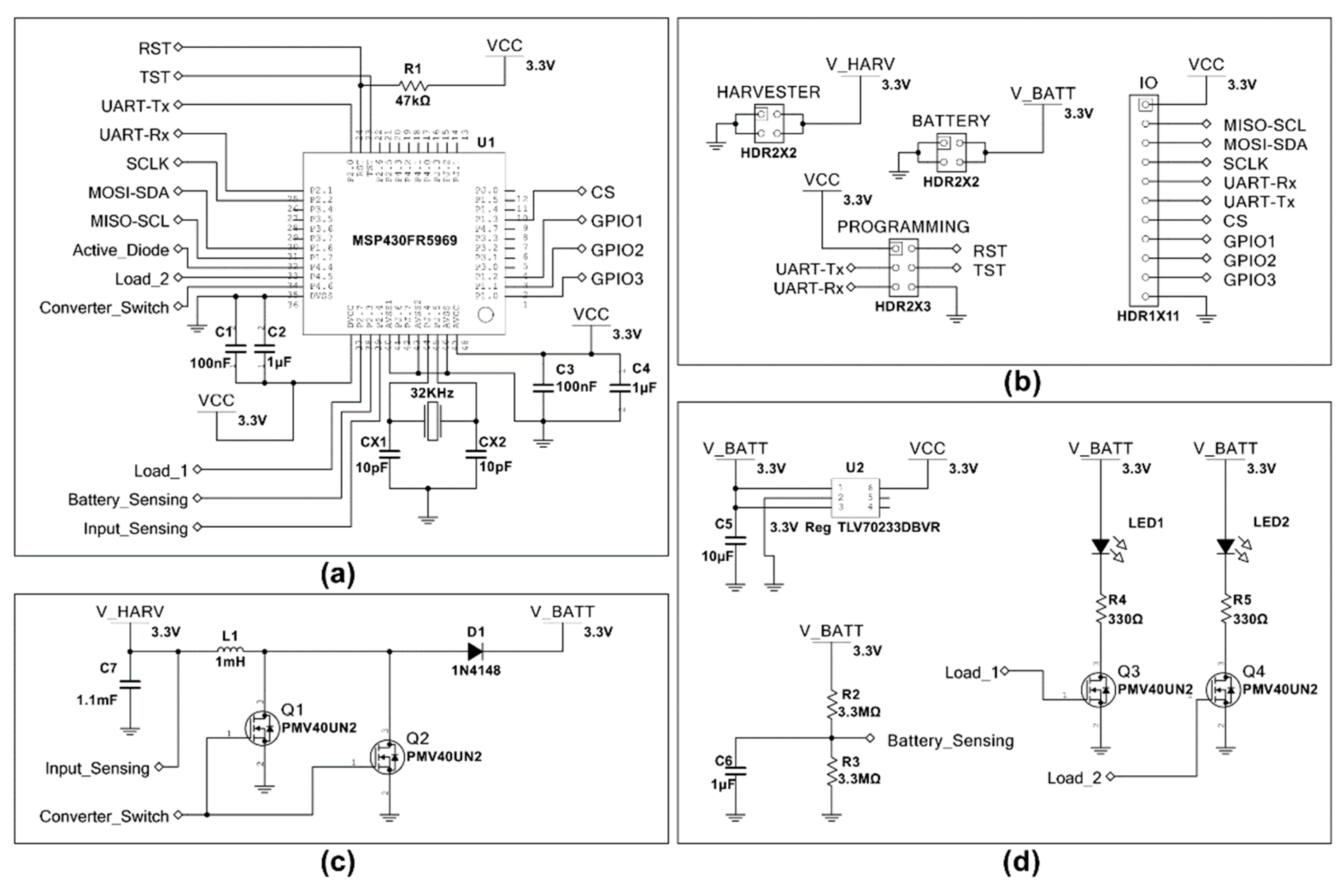
The harvesting unit utilizes MSP430FR5969, an ultra-low power MCU from Texas Instruments [27], to perform all the required actions, for the successful operation of the system (Figure 2a). The MSP430FR5969 offers extremely low power consumption (20 nA in deep sleep mode) as well as an analog to digital converter (ADC) with very low power consumption (a few uA), which can work in continuous mode while the main core is in sleep mode—a feature required by the proposed system. Additionally, the MCU can be used for extra tasks depending on different case study applications. Thus, unused input/output (I/O) pins are offered on the designed Printed Circuit Board (PCB) (Figure 2b).
The main purpose of the MCU is to control an inductive DC–DC boost converter (Figure 2c), using an analog input to measure the voltage level at the input of the boost converter (Input_Sensing wire), and a digital output to control its low side switch (Converter_Switch wire). The power consumption of the system increases with the oscillating frequency of the converter, as a higher sampling rate is required by the ADC and the MCU is active more often. Thus, a big size input capacitor and inductor are used for the implementation of the boost converter (1.1 mF, 1 mH) in order to reduce the oscillating frequency. The maximum oscillating frequency of the converter for the maximum input power (300 mW at 2 V) remains below 100Hz.
The system is powered by a 3.7–4.2 V Li-ion rechargeable battery. The MCU is supplied with 3.3 V using a low drop voltage regulator. Using a resistor divider and a second analog input (Battery_Sensing wire) the MCU can monitor the voltage of the battery. If the battery voltage reaches the maximum value (4.2 V), the MCU can draw the excess power using two loads (Load_1 and Load_2 wires) as shown in Figure 2d. A custom-made double layer PCB with 29 × 29 mm dimensions is used for the final implementation of the system.

3. Input Matching and Time-Based Input-Power Sensing

In this section, the operation of the boost converter is described. The MCU monitors the voltage level at the input of the boost converter using its internal ADC in continuous mode, with a 2 KHz sampling rate. This sampling rate is sufficient, considering that a big input capacitor and inductor are used for the boost converter, leading to a maximum possible oscillating frequency of 100 Hz. Each time the input voltage exceeds a predetermined threshold voltage level, the MCU activates the low side switch for a predetermined time window, discharging the capacitor. This way, the voltage level at the input of the boost converter remains constant with a small ripple that depends on the active time of the low side switch. Thus, by adjusting the threshold voltage, the MCU can control the power drawn at the input of the boost converter and alter its input resistance.
Each pulse created by the MCU transfers an amount of energy from the input capacitor to the inductor and finally to the battery. The amount of energy transferred at each pulse depends on the current threshold voltage, the inductance value of the inductor (L1), the capacitance value of the input capacitor (C7), the active time duration of the low side switch and the battery voltage (V_BATT). All of the above parameters excluding the threshold voltage remain constant during the operation of the converter. Thus, for fixed threshold voltage, a fixed amount of energy will be transferred from the capacitor to the inductor at each oscillation. The frequency of the oscillations will therefore be proportional to the input power of the converter.
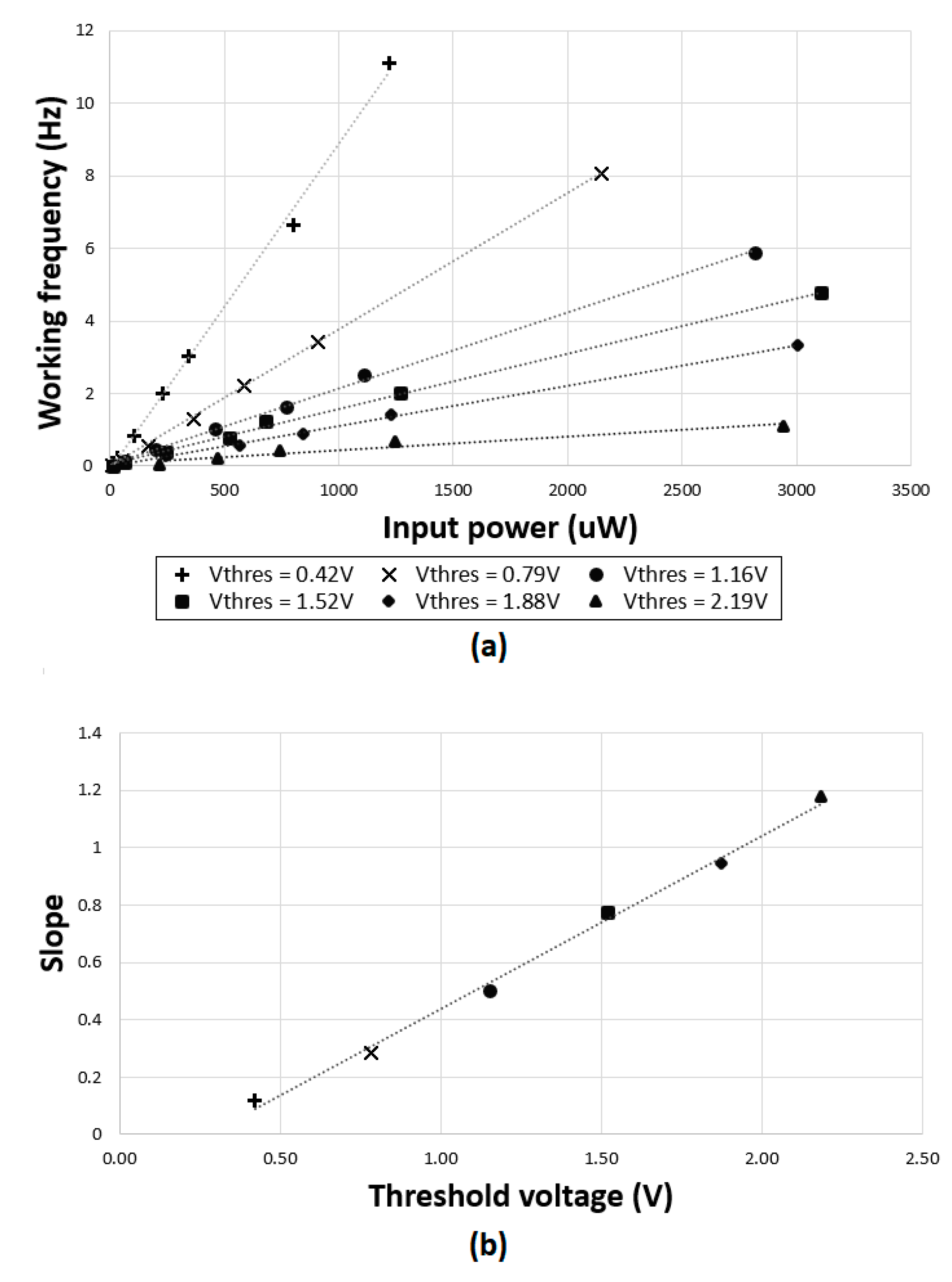
Figure 3a shows measurements of the relation between the working frequency and the power at the input of the converter (input power), for various threshold voltages. In Figure 3b, the slope of each line versus the threshold voltage used is plotted. As shown, the slope is proportional to the threshold voltage used. This way, the MCU can calculate the input power of the converter using Equation (1), where Vthres is the threshold voltage used and Fosc is the frequency of the oscillation observed.
Pin = (0.6032 × Vthres − 0.1672) × Fosc
The boost converter can operate for input voltage that ranges between 420 mV and 2.2 V and for input power that ranges between 10 uW and 300 mW. The average efficiency is 35% for input power below 500 uW and 70% for input power greater than 500 uW. The power consumption of the system is 73.5 uW at 4.2 V, including the consumption MCU and battery management unit. The measurements in this section shown in Figure 3 were performed in lab conditions, in order to accomplish higher accuracy for the calibration of the system and the power function equation extraction. In the measurement setup, the current source used to provide power at the input of the boost converter was able to deliver a maximum power of approximately 3 mW. However, the system operates successfully for input power up to 300 mW, as it was tested in real conditions (see Section 4).

4. Global Maximum Power Point Tracking

For the operation of the boost converter, the MCU activates the low side switch of the boost converter, for a fixed amount of time, whenever the input voltage of the harvesting unit exceeds a predetermined threshold voltage. This is achieved using an internal ADC and a digital comparator to monitor the input voltage, while the main core of the MCU is in sleep mode (Figure 4). The ADC is triggered by an internal timer (Timer 1) with a sampling rate of 2KHz. Also, the MCU uses a second internal timer (Timer 0) to measure the rate of the oscillations and to calculate the input power using Equation (1). This way, the MCU can adjust the threshold voltage in order to track the MPP. Various algorithms can be used for the MPPT since an MCU is used. Two different algorithms were compared in this work, both using Equation (1) and six oscillation periods at each threshold voltage, to measure the oscillating frequency and determine the input power. Using this information, both algorithms are able to track the optimal threshold voltage that will allow the converter to draw the maximum power from the photovoltaic cell.
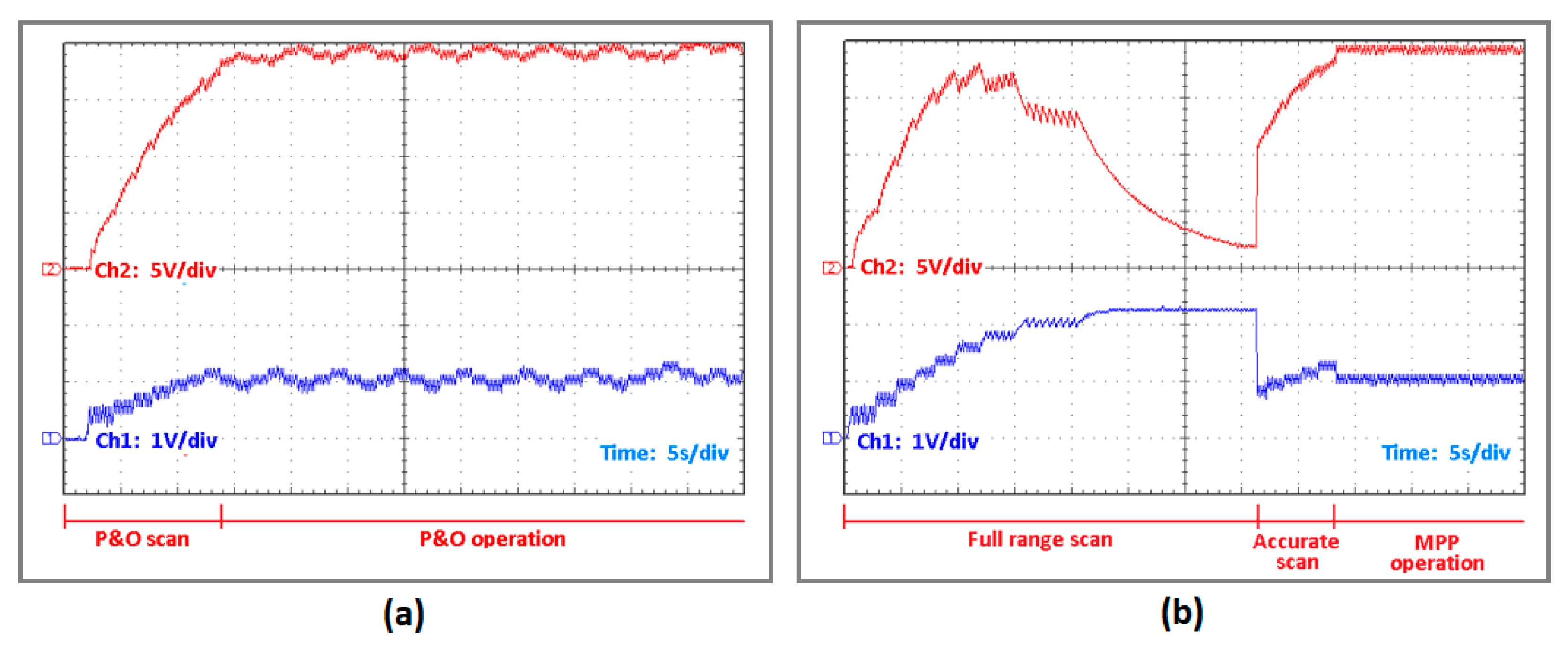
The first algorithm implements the P&O method. Starting from the lowest threshold voltage (0.42 V), it calculates the input power and performs a step regarding the previous measurement, in order to track the MPP. The main disadvantage of the P&O method is that it oscillates around the MPP, spending only half of the time at the actual MPP. Also, in case of partial shading conditions, the algorithm can stop at a local MPP instead of the global MPP. Figure 5a shows the input voltage (Ch1 bottom) and the output voltage (Ch2 top) on a 1 MΩ load and 4.7 uF capacitor.
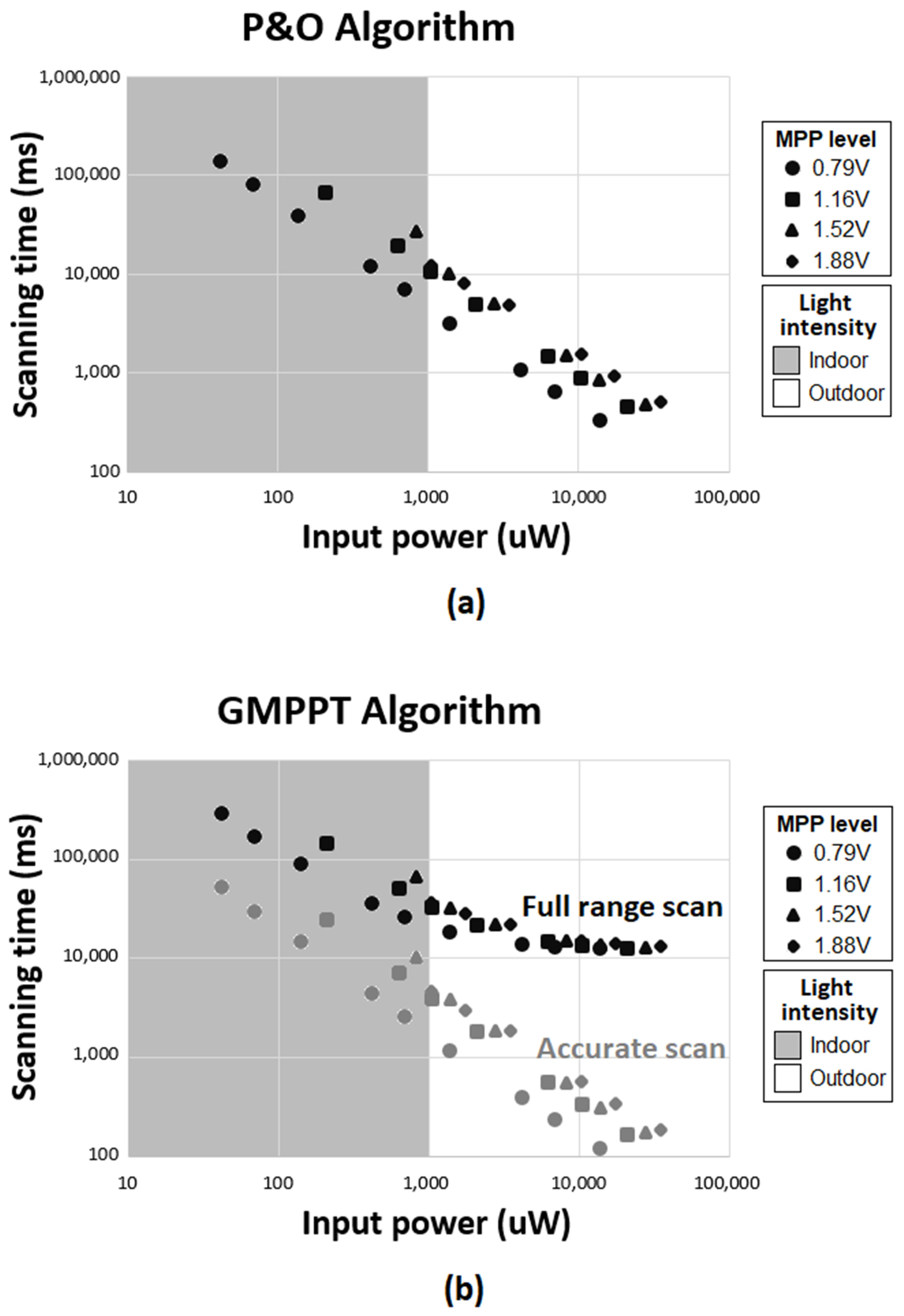
The second algorithm tracks the global MPP, calculating the input power for every threshold voltage between 0.42 and 2.2 V. Initially, the algorithm performs a “Full range scan”, changing the threshold voltage by 200 mV steps. After that, it performs an “Accurate scan” in the neighborhood of the detected MPP using 100 mV steps. Finally, the algorithm stores the maximum power detected. If a change in the input power is detected that exceeds ±15%, the system returns to the “Accurate scan” state. If a change in the input power is detected that exceeds ±30% then the system returns to the “Full range scan” state. Figure 5b shows the input voltage (Ch1 bottom) and the output voltage (Ch2 top) on a 1 MΩ load and 4.7 uF capacitor. The main drawback of the GMPPT algorithm is the scanning time required. The scanning time depends on the input power as shown in Figure 6.
As shown, the P&O MPPT algorithm’s scanning time ranges from 10 to 300 s, while the GMPPT algorithm’s scanning time ranges from 10 to 300 s for the “Full range scan” and 100 ms up to 30 s for the “Accurate scan” modes, respectively. This means that whenever a sudden change in irradiance greater than 30% of the saved power occurs, the MPPT will perform with sub-optimal efficiency for a certain amount of time. During the “Full range scan” mode, the average MPPT efficiency is approximately 50%, and during the “Accurate scan” mode the average MPPT efficiency is approximately 70%. A sudden change in irradiance rarely occurs in indoor conditions where the input power is low (large scanning time). On the other hand, in outdoor conditions, irradiance changes occur more often, but the available power is much higher (small scanning time). Additionally, the 15% and 30% thresholds used that redirect the software to the “Accurate scan” or “Full range scan” modes, respectively, further improve the scanning time of the GMPPT algorithm, as a sudden change in irradiance greater than 30% occurs extremely rarely. Using a voltage source (Vsource) with a series-connected resistor (Rsource), both algorithms were measured (Table 1). In this configuration, the MPP voltage (Vmpp) is half the voltage of the voltage source.
Finally, using a portable LUX meter [28], the system was evaluated for various light intensities. We used LL200-2.4–75, a flexible light harvester by PowerFilm, with a size of 73 × 94 mm [29]. The light harvester can provide power ranging from 50 uW in low-indoor light (50 LUX) to 250 mW max in outdoor conditions (120,000 LUX). In Table 2, the power provided to the battery at different light intensities is shown. As the harvesting system described is consuming 73.5 uW at 4.2 V (including the consumptions of the MCU, the voltage regulator and the battery sensing resistor divider), the battery charging begins for output power greater than 73.5 uW. In Table 3, this work is compared with other state-of-the-art implementations. As shown, the system achieves GMPPT with maximum efficiency, extremely low power consumption and with a very wide power throughput range that allows it to work efficiently both in indoor and outdoor conditions.

5. Prototype Application

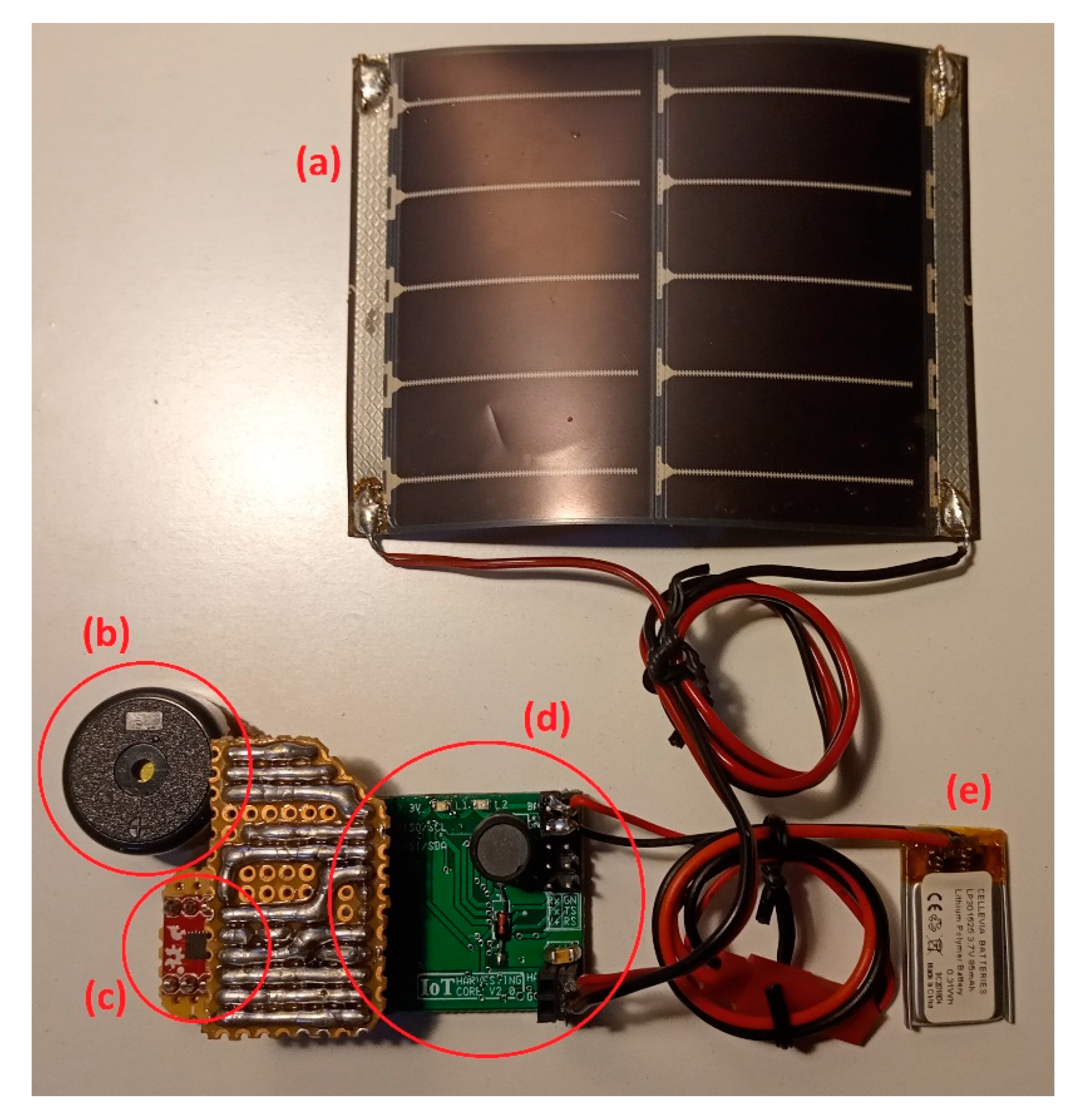
The system described in this paper is developed for use with a prototype earthquake detector (Figure 7), using the ultra-low power consumption accelerometer from Analog Devices, the model ADXL362 [30]. This accelerometer can monitor the acceleration in three axes while consuming only 270 nA in ultra-low power mode and has the ability to trigger the MCU if the acceleration at any axis exceeds a predetermined threshold level.
The overall consumption of the system remains below 75 uW at 4.2 V, including the consumption of the accelerometer. If a change in the acceleration is detected, the MCU activates a buzzer for approximately 20 s. The buzzer consumes on average 1 mA while operating. Using an 80 mAh battery, the buzzer can operate for more than 4000 min. Table 4 shows the expected battery duration in months in case of no earthquake detection, versus the available light. The system can work infinitely with 250LUX of light available at all times.

6. Conclusions

A GMPPT harvesting system with ultra-low power consumption and high tracking efficiency was introduced. Using a time-based power sensing method to measure the input power, it can work with a very wide power range of 10 uW to 300 mW and for input voltages ranging from 420 mV to 2.2 V. Connected to a 73 × 94 mm flexible light harvester, the system can harness any available light energy in both indoor and outdoor conditions, which appears improved in comparison to the literature. An ultra-low power MCU achieves GMPPT with 99.75% average tracking efficiency at the whole operating range, consuming only 73.5 uW at 4.2 V. In Table 3, this work is compared with other state-of-the-art implementations. As shown, the system achieves GMPPT with extremely low power consumption and a very wide power throughput range that allows it to work efficiently both in indoor and outdoor conditions. The system was tested in a realistic scenario, implementing a prototype earthquake-triggered alarm node.

Author Contributions

Conceptualization, K.K.; methodology, K.K., I.S. and V.K.; validation, K.K., V.K. and S.S.; writing—original draft preparation, K.K.; writing—review and editing, K.K., V.K., K.S. and S.S.; supervision, V.K., K.S. and S.S.; All authors have read and agreed to the published version of the manuscript.

Funding

This research has been co-financed by the European Regional Development Fund of the European Union and Greek national funds through the Operational Program Competitiveness, Entrepreneurship and Innovation, under the call RESEARCH—CREATE—INNOVATE (project code: Τ1ΕΔΚ-01679).

Conflicts of Interest

The authors declare no conflict of interest.

References

  1. Nasiri, A.; Zabalawi, S.A.; Mandic, G. Indoor Power Harvesting Using Photovoltaic Cells for Low-Power Applications. IEEE Trans. Ind. Electron. 2009, 56, 4502–4509. [Google Scholar] [CrossRef]
  2. George, A.M.; Kulkarni, S.Y. Performance of Power Converters for Ultra Low Power Systems: A Review. In Proceedings of the 2018 Second International Conference on Advances in Electronics, Computers and Communications (ICAECC), Bangalore, India, 9–10 February 2018; pp. 1–5. [Google Scholar]
  3. Vullers, R.J.; Van Schaijk, R.R.; Visser, H.J.; Penders, J.; Van Hoof, C. Energy Harvesting for Autonomous Wireless Sensor Networks. IEEE Solid-State Circuits Mag. 2010, 2, 29–38. [Google Scholar] [CrossRef]
  4. Liu, X.; Sanchez-Sinencio, E. A Highly Efficient Ultralow Photovoltaic Power Harvesting System with MPPT for Internet of Things Smart Nodes. IEEE Trans. Very Large Scale Integr. (VLSI) Syst. 2015, 23, 3065–3075. [Google Scholar] [CrossRef]
  5. Yue, X.; Kauer, M.; Bellanger, M.; Beard, O.; Brownlow, M.; Gibson, D.; Clark, C.; MacGregor, C.; Song, S. Development of an Indoor Photovoltaic Energy Harvesting Module for Autonomous Sensors in Building Air Quality Applications. IEEE Internet Things J. 2017, 4, 2092–2103. [Google Scholar] [CrossRef]
  6. Estrada-López, J.J.; Abuellil, A.; Zeng, Z.; Sánchez-Sinencio, E. Multiple Input Energy Harvesting Systems for Autonomous IoT End-Nodes. J. Low Power Electron. Appl. 2018, 8, 6. [Google Scholar] [CrossRef] [Green Version]
  7. Huang, Q.; Lu, C.; Shaurette, M. Feasibility study of indoor light energy harvesting for intelligent building environment management. In Proceedings of the International High Performance Buildings Conference, West Lafayette, IN, USA, 12–15 July 2010. [Google Scholar]
  8. Lu, C.; Park, S.P.; Raghunathan, V.; Roy, K. Efficient power conversion for ultra low voltage micro scale energy transducers. In Proceedings of the 2010 Design, Automation & Test in Europe Conference & Exhibition (DATE 2010), Dresden, Germany, 8–12 March 2010; pp. 1602–1607. [Google Scholar]
  9. Long, Y.-S.; Hsu, S.-T.; Wu, T.-C. Energy harvesting characteristics of emerging PV for indoor and outdoor. In Proceedings of the 2016 IEEE 43rd Photovoltaic Specialists Conference (PVSC), Portland, OR, USA, 5–10 June 2016; pp. 796–801. [Google Scholar]
  10. Bol, D.; Boufouss, E.H.; Flandre, D.; De Vos, J. A 0.48 mm2 5 μW–10 mW indoor/outdoor PV energy-harvesting management unit in a 65 nm SoC based on a single bidirectional multi-gain/multi-mode switched-cap converter with supercap storage. In Proceedings of the ESSCIRC Conference 2015—41st European Solid-State Circuits Conference (ESSCIRC), Graz, Austria, 14–18 September 2015; pp. 241–244. [Google Scholar]
  11. Chen, Y.-C.; Pan, C.-P.; Lin, C.-L.; Hwang, C.-H.; Chen, H. Photovoltaic energy harvesting in indoor environments. In Proceedings of the 2018 IEEE International Instrumentation and Measurement Technology Conference (I2MTC), Houston, TX, USA, 14–17 May 2018; pp. 1–5. [Google Scholar]
  12. Tsai, T.-H.; Chen, K. A 3.4 mW photovoltaic energy-harvesting charger with integrated maximum power point tracking and battery management. In Proceedings of the 2013 IEEE International Solid-State Circuits Conference Digest of Technical Papers, San Francisco, CA, USA, 17–21 February 2013; pp. 72–73. [Google Scholar]
  13. Abdelmoaty, A.A.; Al-Shyoukh, M.; Hsu, Y.-C.; Fayed, A.A. A MPPT Circuit with 25 μW Power Consumption and 99.7% Tracking Efficiency for PV Systems. IEEE Trans. Circuits Syst. I: Regul. Pap. 2016, 64, 272–282. [Google Scholar] [CrossRef]
  14. Liu, X.; Sanchez-Sinencio, E. An 86% Efficiency 12 µW Self-Sustaining PV Energy Harvesting System with Hysteresis Regulation and Time-Domain MPPT for IOT Smart Nodes. IEEE J. Solid-State Circ. 2015, 50, 1424–1437. [Google Scholar] [CrossRef]
  15. NDash, S.S.; Padmanaban, S.; Morati, P.K. Maximum Power Point Tracking Implementation by Dspace Control-ler Integrated Through Z-Source Inverter Using Particle Swarm Optimization Technique for Photovoltaic Applications. Appl. Sci. 2018, 8, 145. [Google Scholar]
  16. Danandeh, M.; Mousavi, S.M. Comparative and comprehensive review of maximum power point tracking methods for PV cells. Renew. Sustain. Energy Rev. 2018, 82, 2743–2767. [Google Scholar] [CrossRef]
  17. Weng, X.; He, F.; Zhao, Z.; Lu, T.; Yuan, L. Comparison of several MPPT methods for PV arrays under partially shaded conditions. In Proceedings of the International Conference on Renewable Power Generation (RPG 2015), Beijing, China, 17–18 October 2015; Institution of Engineering and Technology (IET): Beijing, China, 2015; p. 6. [Google Scholar]
  18. Patel, H.; Agarwal, V. Maximum Power Point Tracking Scheme for PV Systems Operating Under Partially Shaded Conditions. IEEE Trans. Ind. Electron. 2008, 55, 1689–1698. [Google Scholar] [CrossRef]
  19. Oubbati, B.K.; Boutoubat, M.; Belkheiri, M.; Rabhi, A. Global maximum power point tracking of a PV system MPPT control under partial shading. In Proceedings of the 2018 International Conference on Electrical Sciences and Technologies in Maghreb (CISTEM), Algiers, Algeria, 28–31 October 2018; pp. 1–6. [Google Scholar]
  20. Gosumbonggot, J.; Nguyen, D.-D.; Fujita, G. Partial Shading and Global Maximum Power Point Detections Enhancing MPPT for Photovoltaic Systems Operated in Shading Condition. In Proceedings of the 2018 53rd International Universities Power Engineering Conference (UPEC), Glasgow, UK, 4–7 September 2018; pp. 1–6. [Google Scholar]
  21. Uprety, S.; Lee, H. 23.6 A 43 V 400 mW-to-21 W global-search-based photovoltaic energy harvester with 350 μs transient time, 99.9% MPPT efficiency, and 94% power efficiency. In Proceedings of the 2014 IEEE International Solid-State Circuits Conference Digest of Technical Papers (ISSCC), San Francisco, CA, USA, 9–13 February 2014; pp. 404–405. [Google Scholar]
  22. Kapić, A.; Zečević, Ž.; Krstajić, B. An efficient MPPT algorithm for PV modules under partial shading and sudden change in irradiance. In Proceedings of the 2018 23rd International Scientific-Professional Conference on Information Technology (IT), Zabljak, Montenegro, 19–24 February 2018; pp. 1–4. [Google Scholar]
  23. Gosumbonggot, J.; Fujita, G. Partial Shading Detection and Global Maximum Power Point Tracking Algorithm for Photo-voltaic with the Variation of Irradiation and Temperature. Energies 2019, 12, 202. [Google Scholar] [CrossRef] [Green Version]
  24. Lu, C.; Park, S.P.; Raghunathan, V.; Roy, K. Low-Overhead Maximum Power Point Tracking for Micro-Scale Solar Energy Harvesting Systems. In Proceedings of the 2012 25th International Conference on VLSI Design, Hyderabad, India, 7–11 January 2012; pp. 215–220. [Google Scholar]
  25. Lopez-Lapena, O.; Penella, M.T.; Gasulla, M. A Closed-Loop Maximum Power Point Tracker for Subwatt Photovoltaic Panels. IEEE Trans. Ind. Electron. 2011, 59, 1588–1596. [Google Scholar] [CrossRef]
  26. Rawy, K.; Kalathiparambil, F.; Maurath, D.; Kim, T.T.-H. A Self-Adaptive Time-Based MPPT With 96.2% Tracking Efficiency and a Wide Tracking Range of 10 μ A to 1 mA for IoT Applications. IEEE Trans. Circ. Syst. I Regul. Pap. 2017, 64, 2334–2345. [Google Scholar] [CrossRef]
  27. Available online: https://www.ti.com/product/MSP430FR5969 (accessed on 13 February 2021).
  28. Available online: https://www.uni-trend.com/html/product/Environmental/Environmental_Tester/Mini/UT383.html (accessed on 13 February 2021).
  29. Available online: https://www.powerfilmsolar.com/products/development-kits/ (accessed on 13 February 2021).
  30. Available online: https://www.analog.com/en/products/adxl362.html (accessed on 13 February 2021).
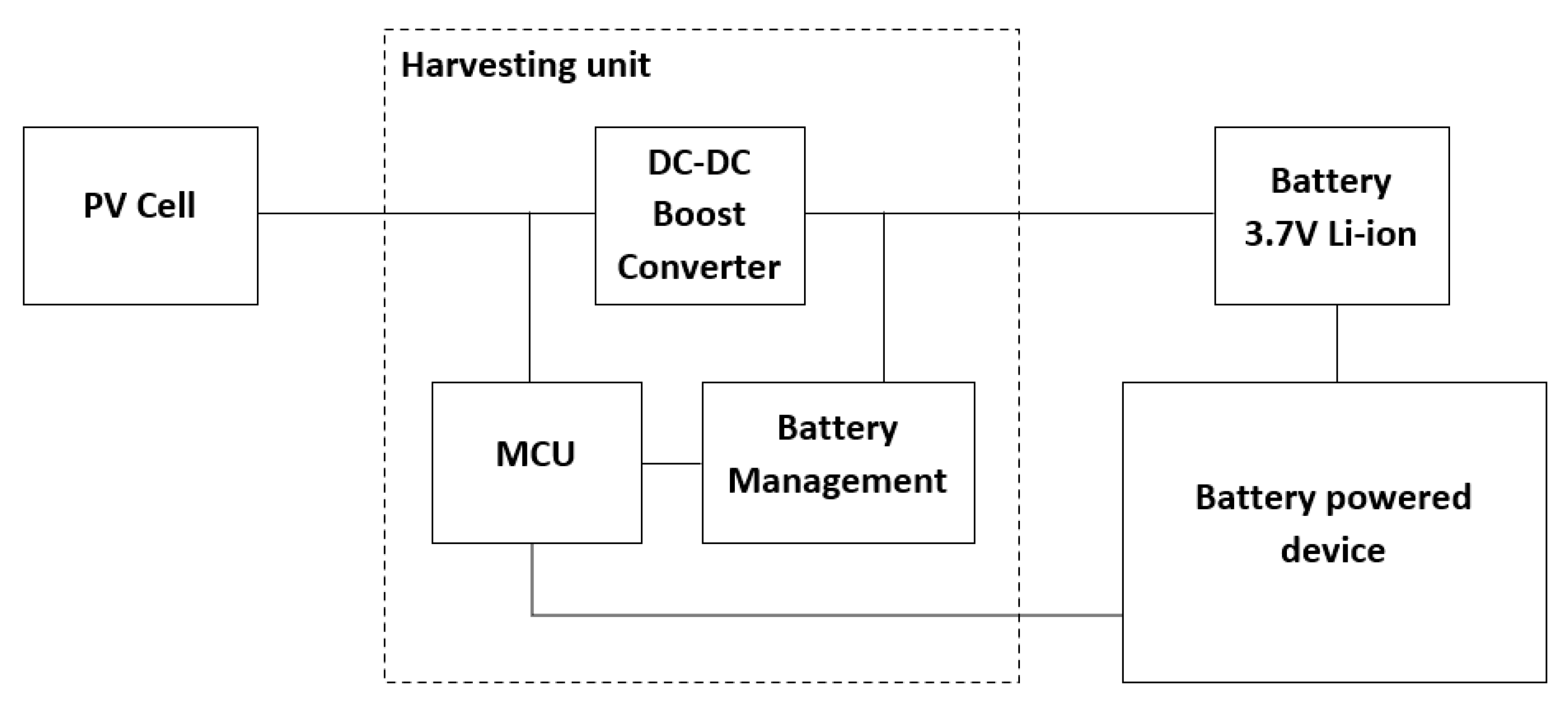
Figure 1. System architecture.
Jlpea 11 00010 g001
Figure 2. System design. (a) Microcontroller (MCU) schematic; (b) Input–output headers; (c) DC–DC boost converter schematic; (d) Battery management schematic.
Jlpea 11 00010 g002
Figure 3. (a) Working frequency versus input power; (b) slope of Figure 3a curves versus the threshold voltage.
Jlpea 11 00010 g003
Figure 4. MCU flow chart.
Jlpea 11 00010 g004
Figure 5. (a) Oscilloscope view of the Perturb and Observe (P&O) algorithm operation; (b) oscilloscope view of the Global Maximum Power Point Tracking (GMPPT) algorithm operation.
Jlpea 11 00010 g005
Figure 6. (a) Scanning time required by the P&O MPPT algorithm for different MPP voltages versus the input power; (b) scanning time required by the GMPPT algorithm for different MPP voltages versus the input power.
Jlpea 11 00010 g006
Figure 7. (a) 73 × 94 mm PowerFilm PV cell; (b) buzzer; (c) ADXL362 accelerometer; (d) proposed harvesting system; (e) 80 mAh 3.7 V Li-ion battery.
Jlpea 11 00010 g007
Table 1. Algorithm performance comparison.
Input configurationVsource (V)112233
Rsource (Ω)10,000180010,000180010,0001800
Vmpp (V)0.50.5111.51.5
Max input power (uW)251391005562251250
P&O algorithmScanning time (s)601565157015
Detected Vmpp (V)0.650.650.880.931.391.39
Input power (uW)22.63126.8898.56552.60223.791243.28
Tracking accuracy (%)69.2070.6088.0092.7092.6792.67
Tracking efficiency (%)90.5191.3698.5699.4799.4699.46
GMPPT algorithmScanning time (s) 1240802155219038
Detected Vmpp (V)0.540.540.990.981.521.44
Input power (uW)24.82138.1399.99555.41224.961248.00
Tracking accuracy (%)91.6092.6098.9098.4098.6796.00
Tracking efficiency (%)99.2999.4599.9999.9799.9899.84
1 Time required for a “Full range” scan.
Table 2. Power provided to the battery.
Light IntensityPbatt (uW)
No light 0 LUX−73.5 3
Low indoor 1 50 LUX−55 3
Home 1 270 LUX17
Office 1 870 LUX271
Rainy 2 14,000 LUX7447
Cloudy 2 47,000 LUX29,411
Sunny 2 120,000 LUX71,537
1 Indoor lighting. 2 Outdoor lighting. 3 Power drown from the battery.
Table 3. Performance summary and comparison.
Ref No.TechnologyMPPT MethodMPPT Efficiency (%)Power ThroughputPower Consumption
[26]65 nm CMOSP&O96.26–600 uW5.1 uW
[14]0.18 um CMOSP&O860–21 uW12 uW
[4]0.18 um CMOSP&O890–29 uW20 uW
[13]0.18 um BiCMOSP&O96–99.7700 mW25 uW
[12]TSMC 0.35 umP&O89500 mW3.4 mW
[25]DiscreteP&O99.41–100 mW3.4 mW
[24] 1IBM 45 nmGlobal99.8140–440 uW180 uW
[21]0.35 um HVCMOSGlobal99.90.4–21.1 W10.65 mW
[18]DiscreteGlobal99.61.5 KWN/A 2
[20]DiscreteGlobal99.95–500 WN/A 2
This workDiscreteGlobal99.7510 uW–300 mW73.5 uW
1 Post-layout simulation results. 2 Power consumption not available, in the range of mW.
Table 4. Battery duration in months (80mAh 3.7V).
Light IntensityCharging Time
No Light2 min/day4 min/day15 min/day6 h/day20 h/day
Home 1 270 LUX5.45.45.45.57.0Inf 3
Office 1 870 LUX5.45.45.55.6Inf 3Inf 3
Rainy 2 14,000 LUX5.46.16.9Inf 3Inf 3Inf 3
Cloudy 2 47,000 LUX5.48.3Inf 3Inf 3Inf 3Inf 3
Sunny 2 120,000 LUX5.4Inf 3Inf 3Inf 3Inf 3Inf 3
1 Indoor lighting. 2 Outdoor lighting. 3 The battery remains perpetually charged.
Publisher’s Note: MDPI stays neutral with regard to jurisdictional claims in published maps and institutional affiliations.