
Simulation-Based Approach for Studying the Balancing of Local Smart Grids with Electric Vehicle Batteries

Abstract
:1. Introduction
2. Simulation-Based Approach
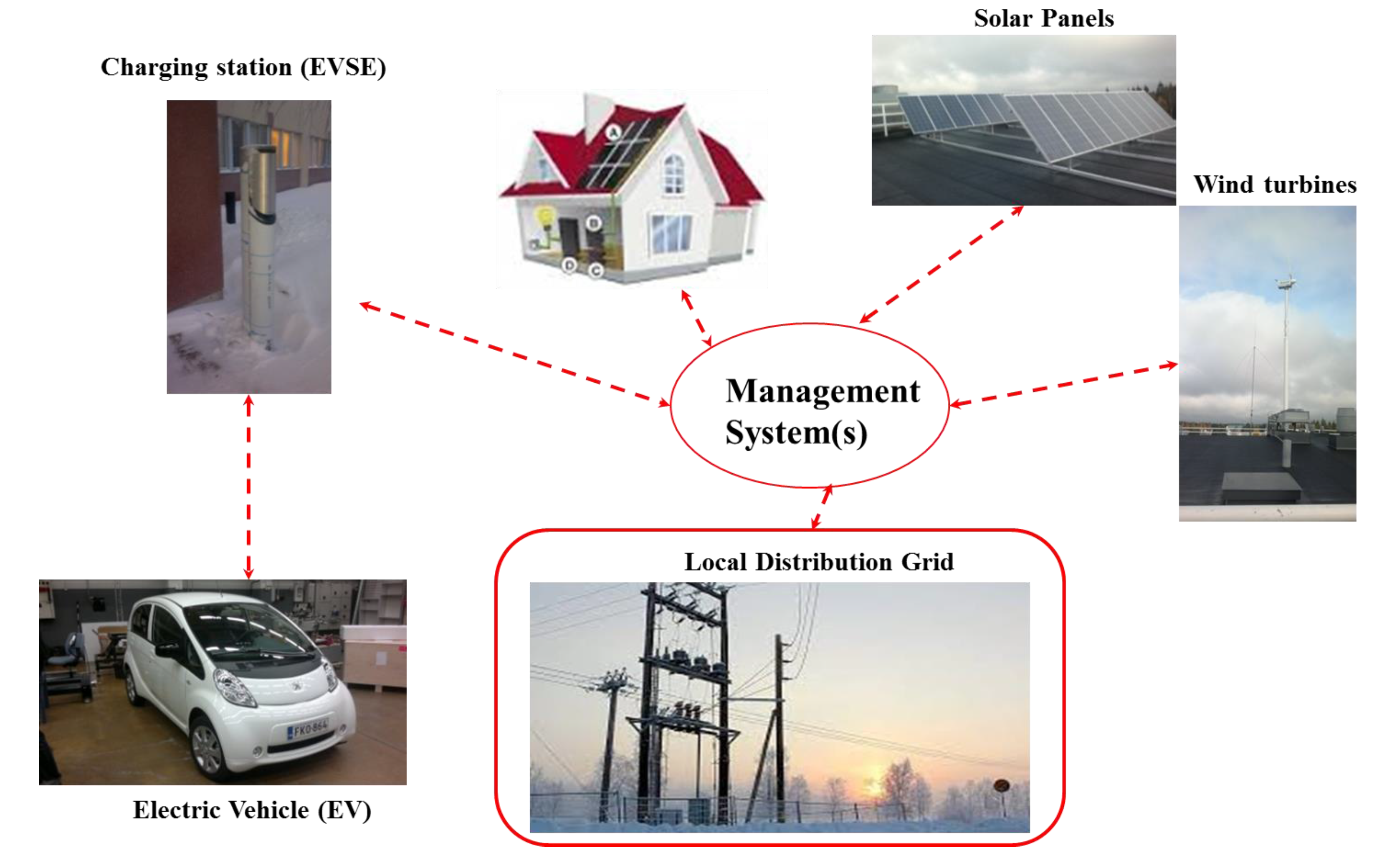
2.1 Smart Grid with Electric Vehicles
2.2 Balancing Scenario

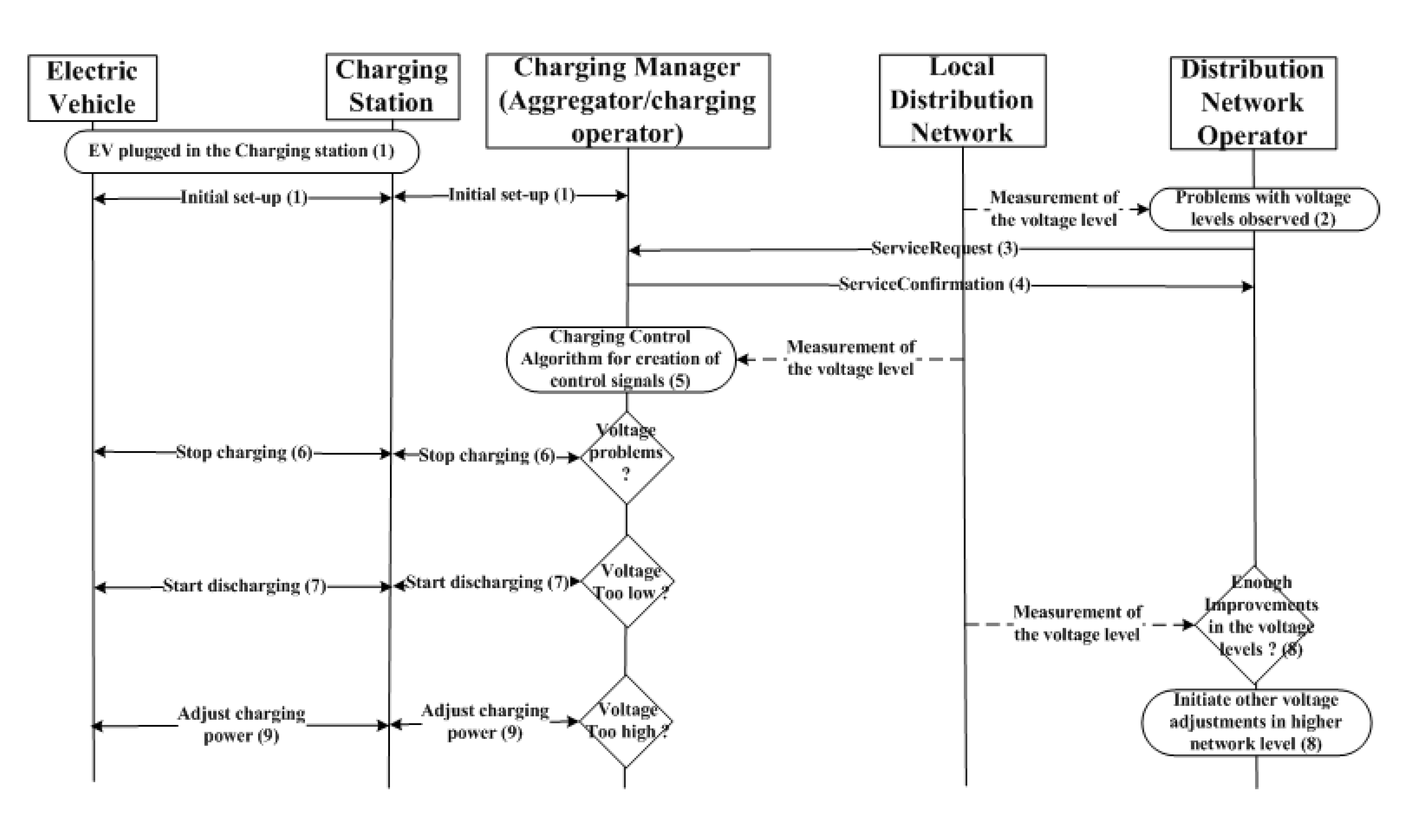
- An electric vehicle has been connected to the charging station. The charging process is initialized, and can be in an active or idle state.
- Problems with voltage levels in a local low voltage distribution grid are observed.
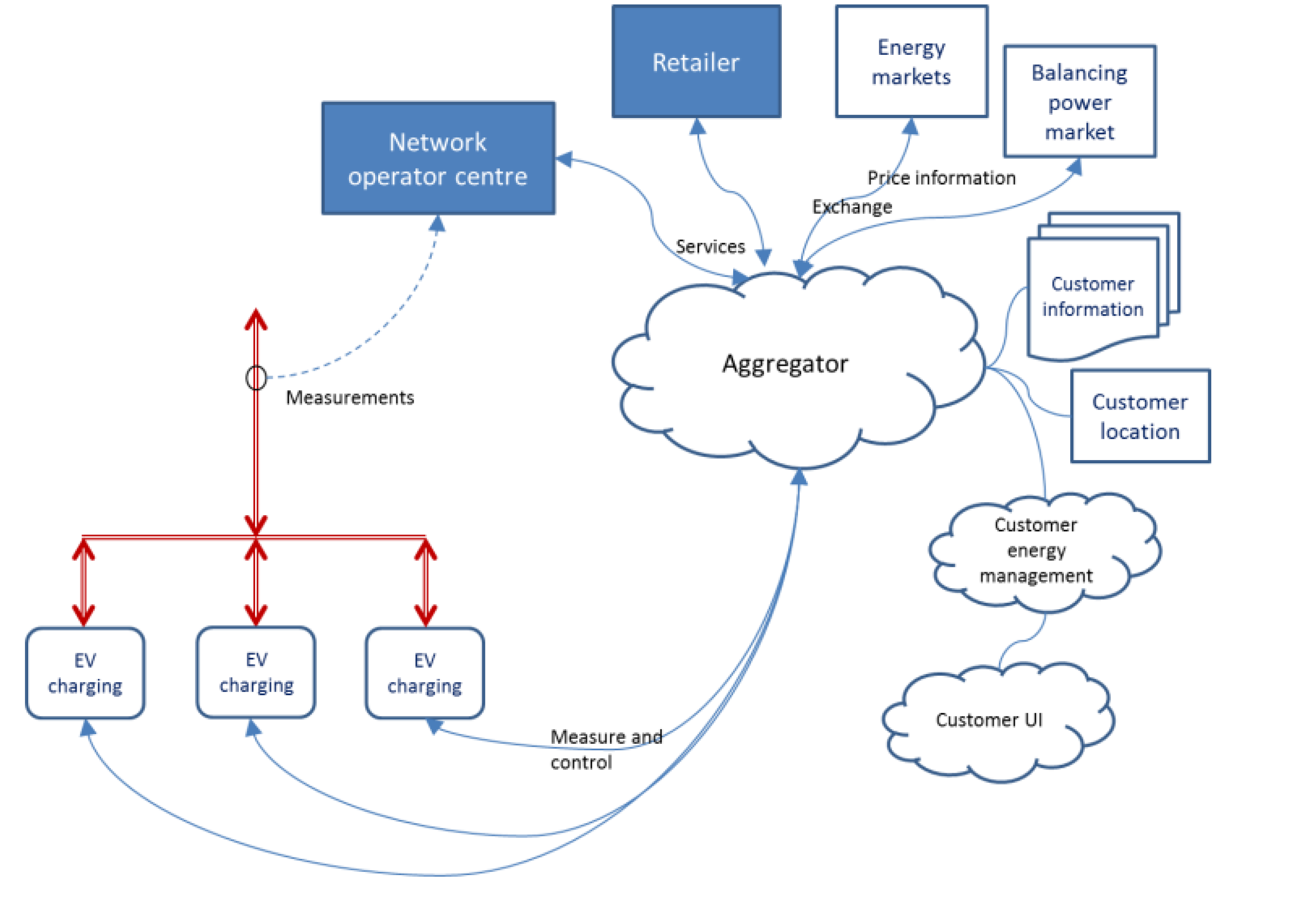
- The distribution network operator issues a service request, including, for instance, the specified network area, the necessary control actions, and the duration.
- The aggregator or charging operator confirms receipt of the request and the ability to fulfill it.
- The charging management system of the aggregator or the charging operator issues the required control signals to the selected group of charging stations. The charging of selected electric vehicles is adjusted according to the control signals.
- If there are low voltage problems, the charging of selected vehicles can be stopped.
- Vehicles may start discharging their batteries into the distribution network.
- As a result, the voltage profile starts to normalize. At the same time, the distribution network operator may also perform some slower voltage adjustments on higher distribution network levels.
- After improvements in the voltage levels, electric vehicles can be returned to charging mode in a controlled manner.

2.3 Simulation-Based Approach
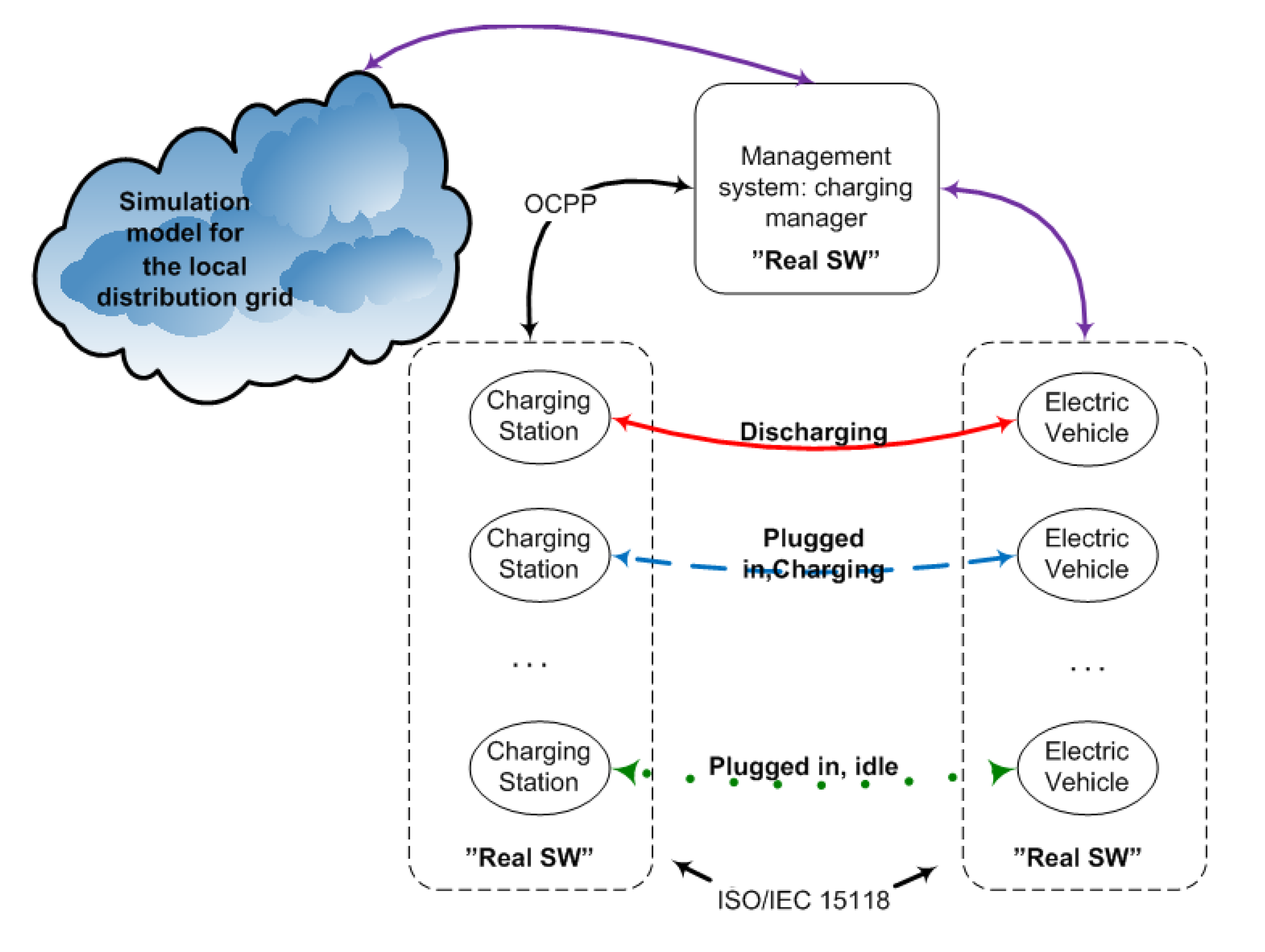
3. Simulation System
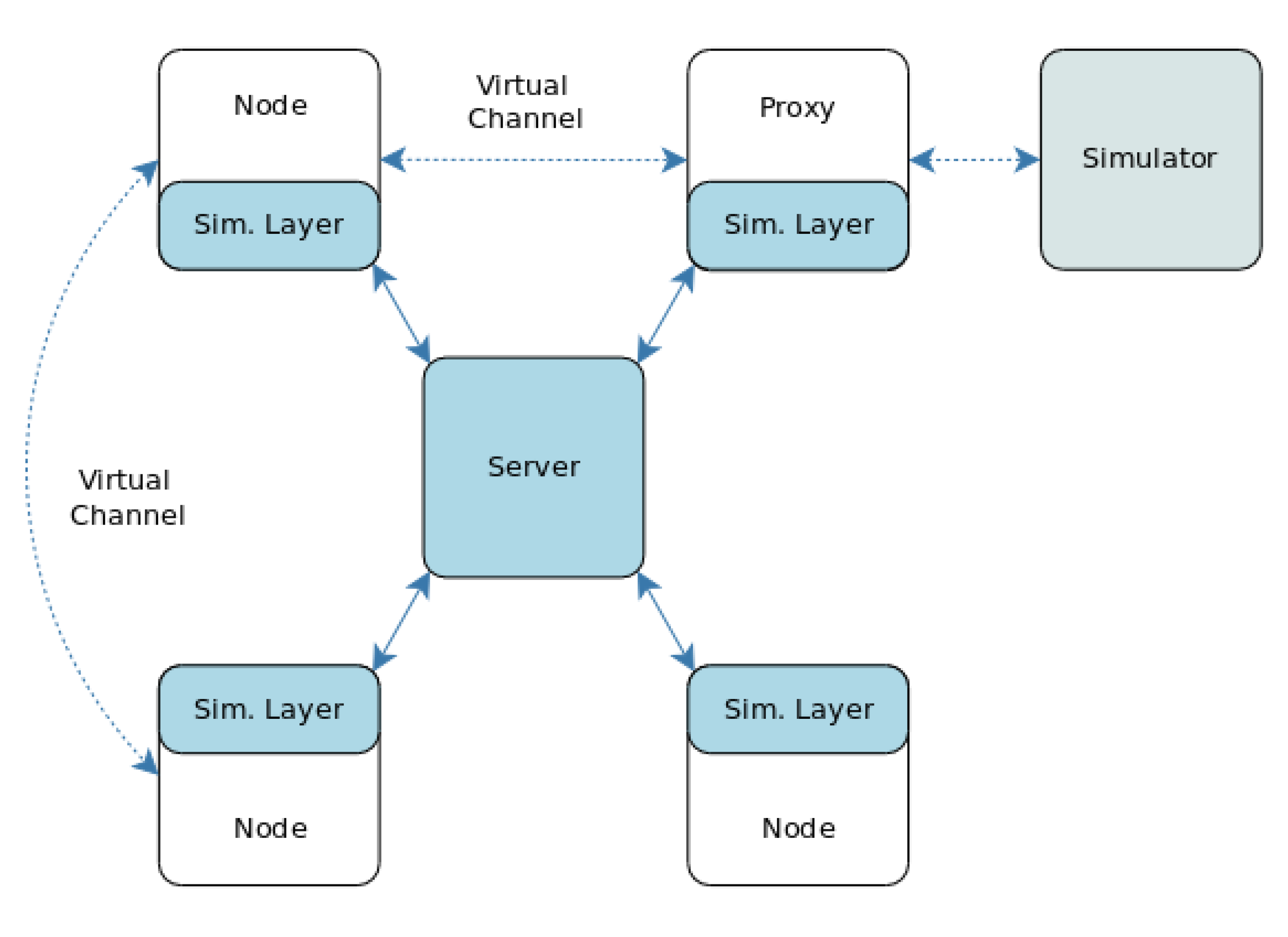
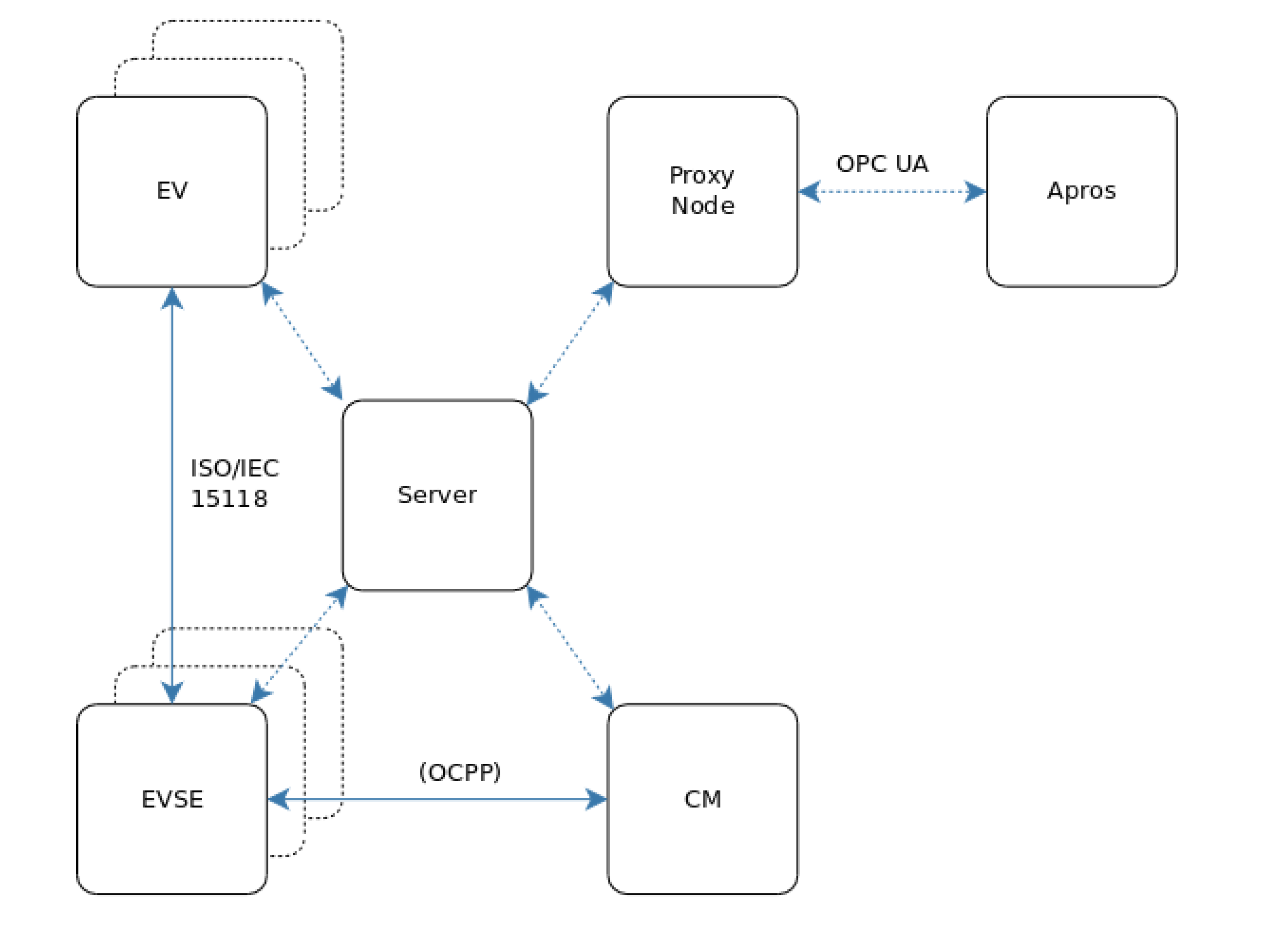
3.1 Architecture
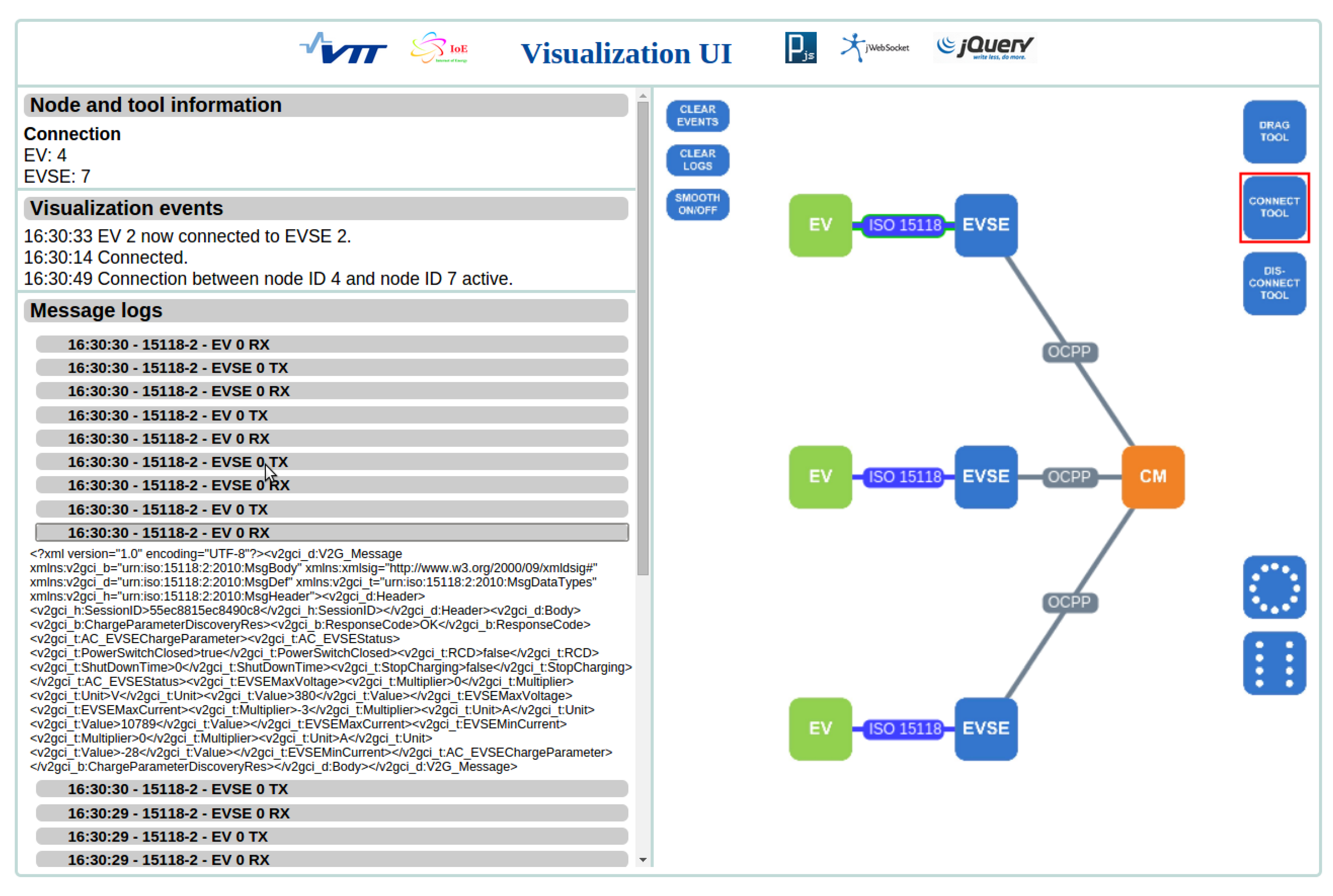
3.2 User’s View of the Simulation
- The Graphical View Window shows a real-time visual presentation of the simulation process. Simulation entities and their connections are illustrated. In the view, the user can select various tools to manipulate the simulation or the visuals. Actions such as adding nodes and creating connections can be performed, as well as dragging and arranging the nodes according to user preferences.
- The Node and Tool Information Window shows relevant information about the node or the tool that is currently selected from the Graphical View. This information can, for example, contain a subset of the EV node’s battery status information or a tooltip for a specific tool, such as the dragging tool.
- The Simulation Events Window shows time-stamped events describing the simulation flow. These include, for example, changes in the connection status between nodes and the speed of the simulation visualization.
- The Message Log Window lists the content of application protocol messages, such as ISO/IEC 15118, sent using the connection between two nodes that is currently selected in the Graphical View. Each of the listed messages can be expanded to show the message content.

3.3 Simulation Set-Up
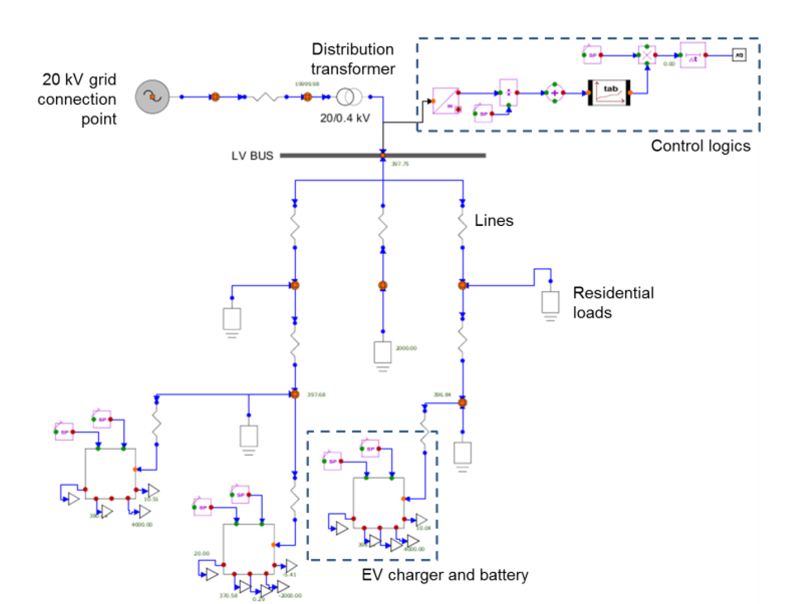
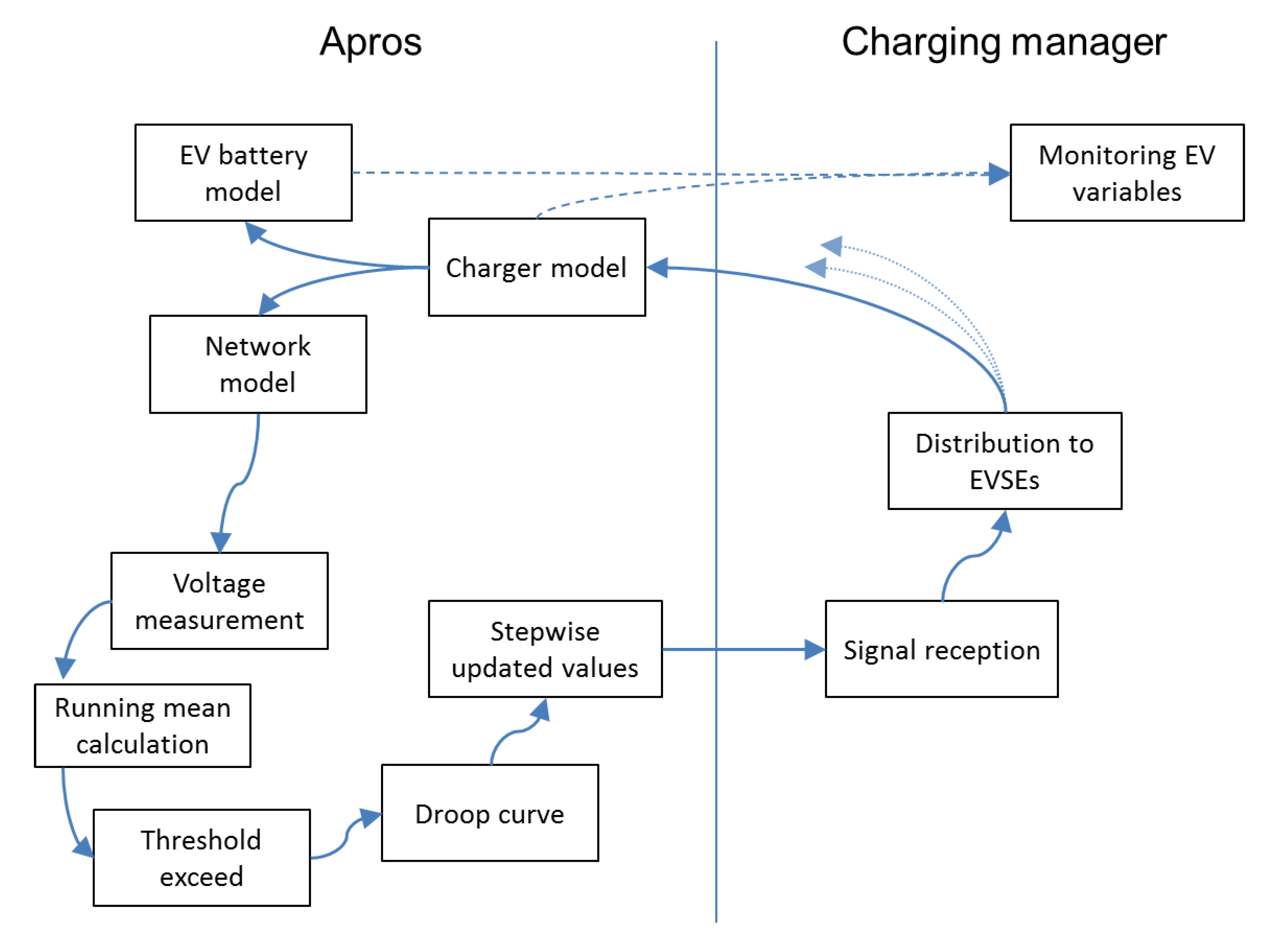
- EV nodes represent individual electric vehicles. They are mapped to electric batteries in the Apros power network model. The main task of an EV module is to initiate and terminate individual EV charging sessions.
- EVSE nodes represent electric vehicle supply equipment. They form the EV’s interface with the smart grid, manage charging parameter negotiations of individual charging sessions, and adjust the charging process according to the evolving power quota. EVSEs are mapped to inverters between the battery and the network in the power network model.
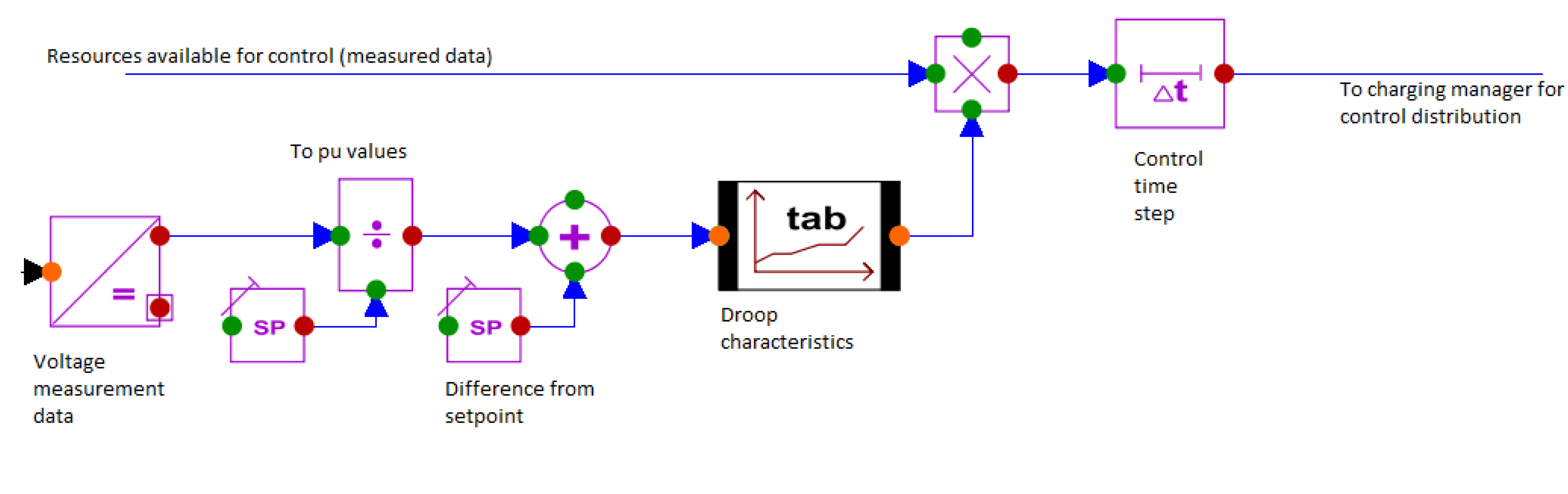
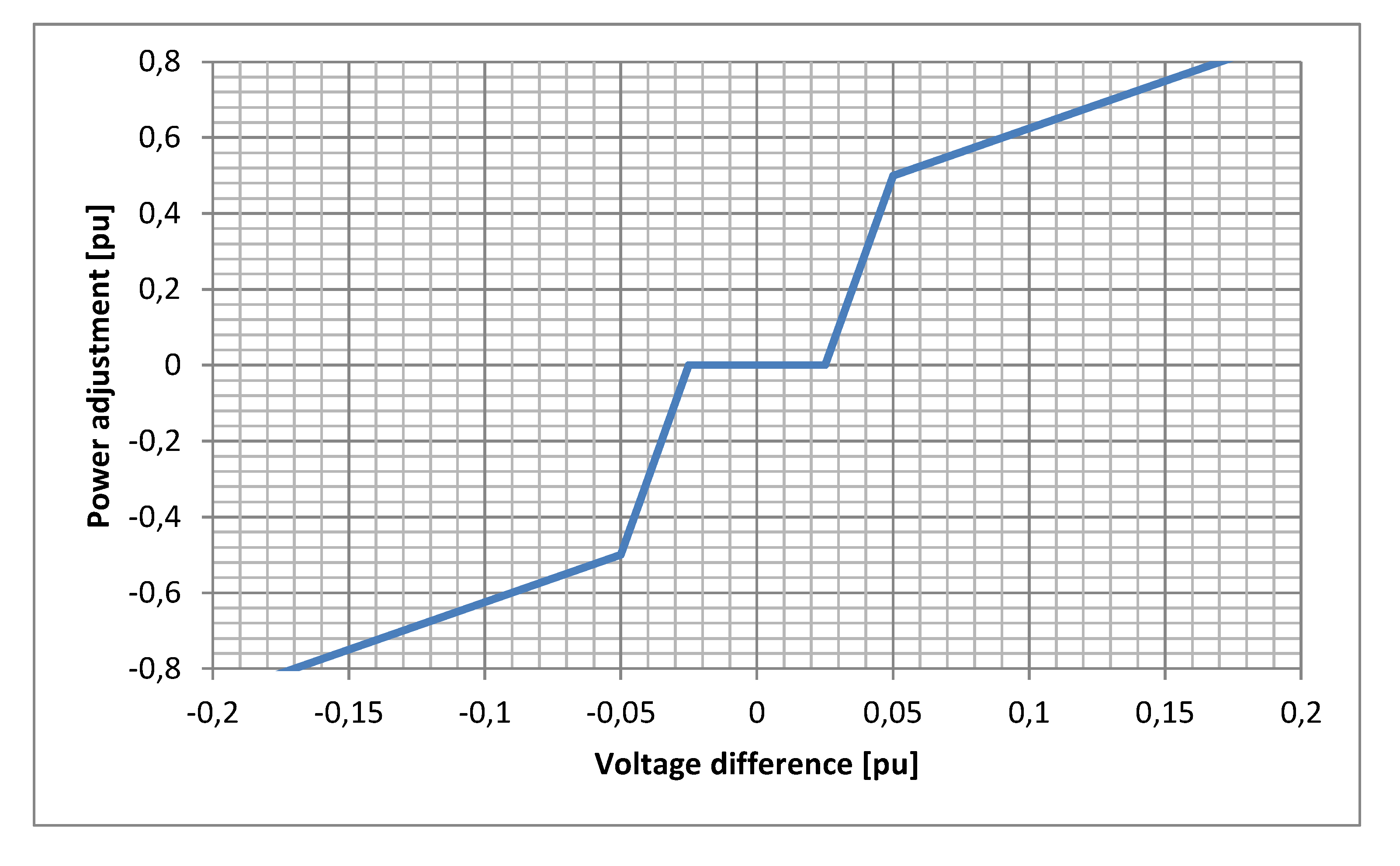
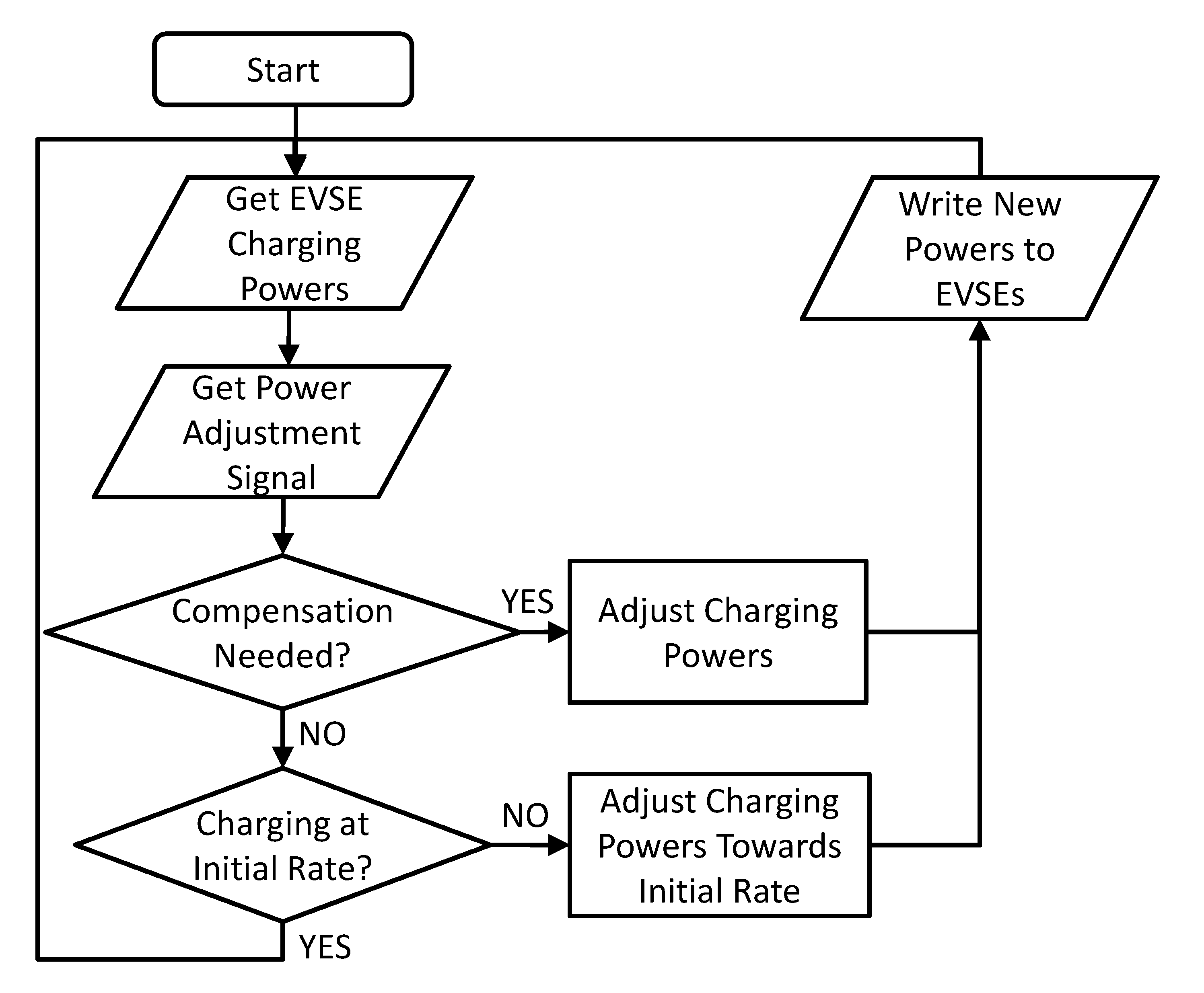
- The Charging Manager (CM) node represents a charging management system that manages multiple EVSEs, e.g., a charging station or charging station network. It contains a decision algorithm that allocates and adjusts the maximum power quotas that the individual EVSEs are allowed to use for the charging sessions they are controlling, with the overall aim of balancing power generation and consumption in the local grid. The CM node does not contain a counterpart in the power network model, but it is a control system that operates on top of the traditional power grid according to feedback it receives from the grid.

4. Simulation Steps: Smart Charging with Local Distribution Grid Management
4.1 Simulation Process

| Parameter Name | Value | Required by |
|---|---|---|
| Maximum controllable load | 12.6 kW | simulation model, CM |
| Maximum EVSE charging power | 4.1–4.3 kW per EVSE | simulation model, CM |
| Maximum EVSE discharging power | 8.1–8.3 kW per EVSE | simulation model, CM |
| Non-controllable load, initial | 10 kW | simulation model |
| Non-controllable load, maximum | 20 kW | simulation model |
| Voltage control threshold (min) | 390 V | simulation model |
| Voltage control threshold (max) | 410 V | simulation model |
| Control signal time step | 1 s | simulation model |
| Voltage ramp-up step | 1/12th of EVSE maximum charging power | CM |
| Distribution Transformer | |
|---|---|
| Winding voltages | 20/0.4 kV |
| Nominal power | 10 kVA |
| Short circuit impedance | 4% |
| No-load current | 0.2 A |
| Lines on LV level | |
| Resistance per length | 0.13 ohm/km |
| Inductance per length | 250e-6 H/km |
| Capacitance per length | 260e-9 F/km |
| EV Battery | |
| Type | Lithium-Ion |
| Rated energy | 28 kWh |
| Rated capacity | 70 Ah |
| Nominal system voltage | 407 V |
| Nominal cell voltage | 4.1 V |
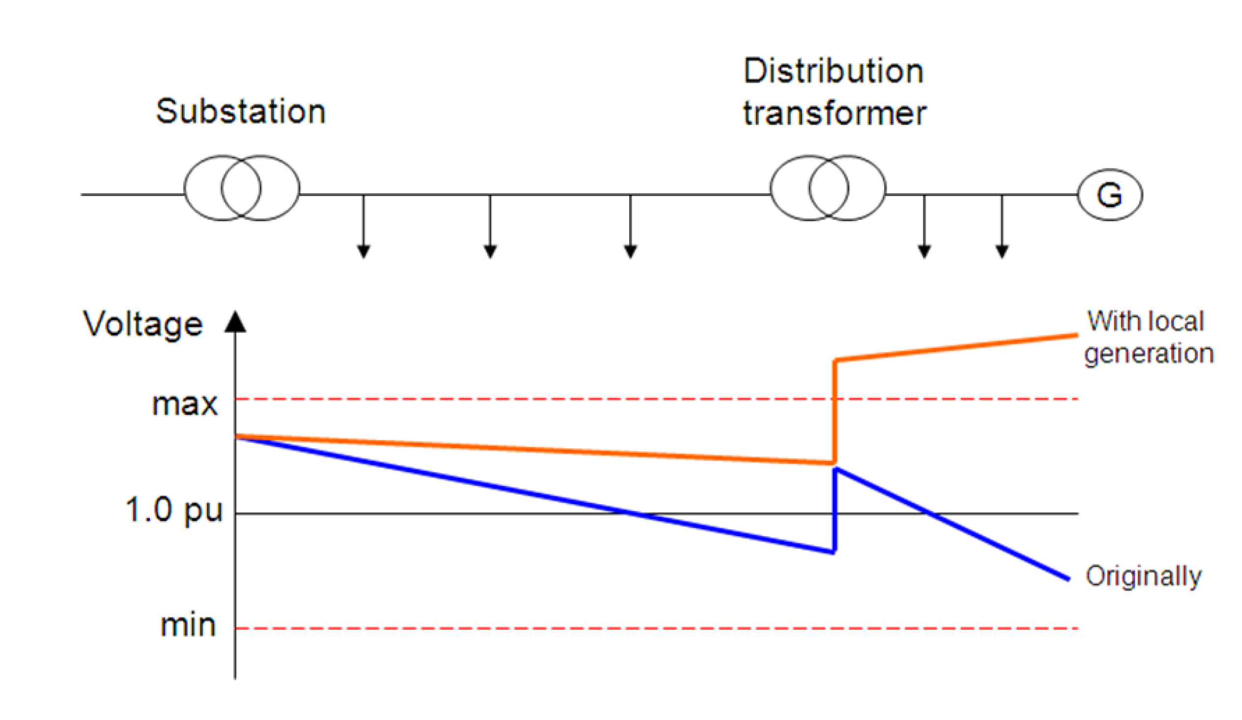
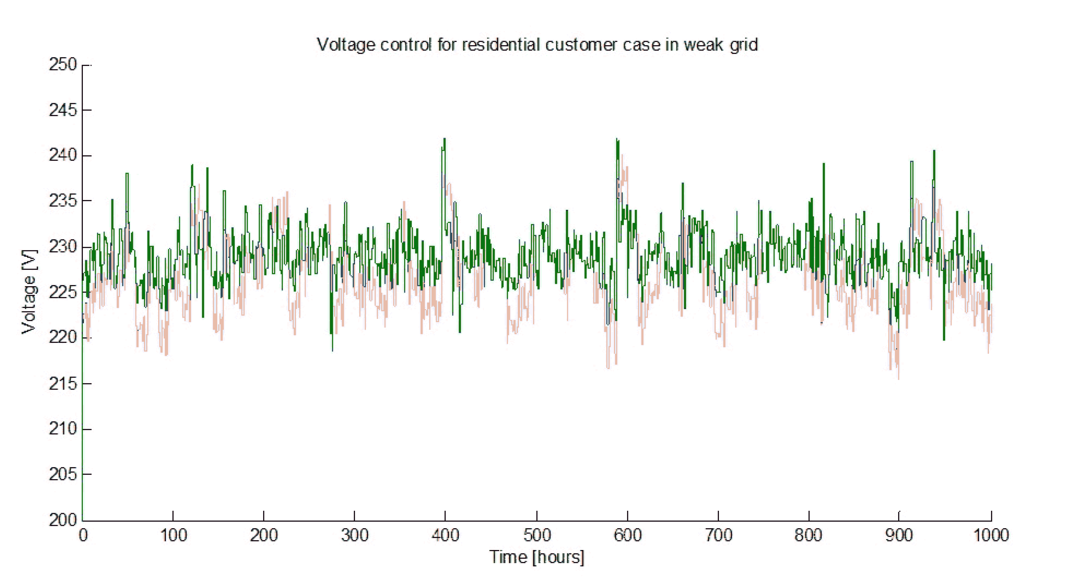
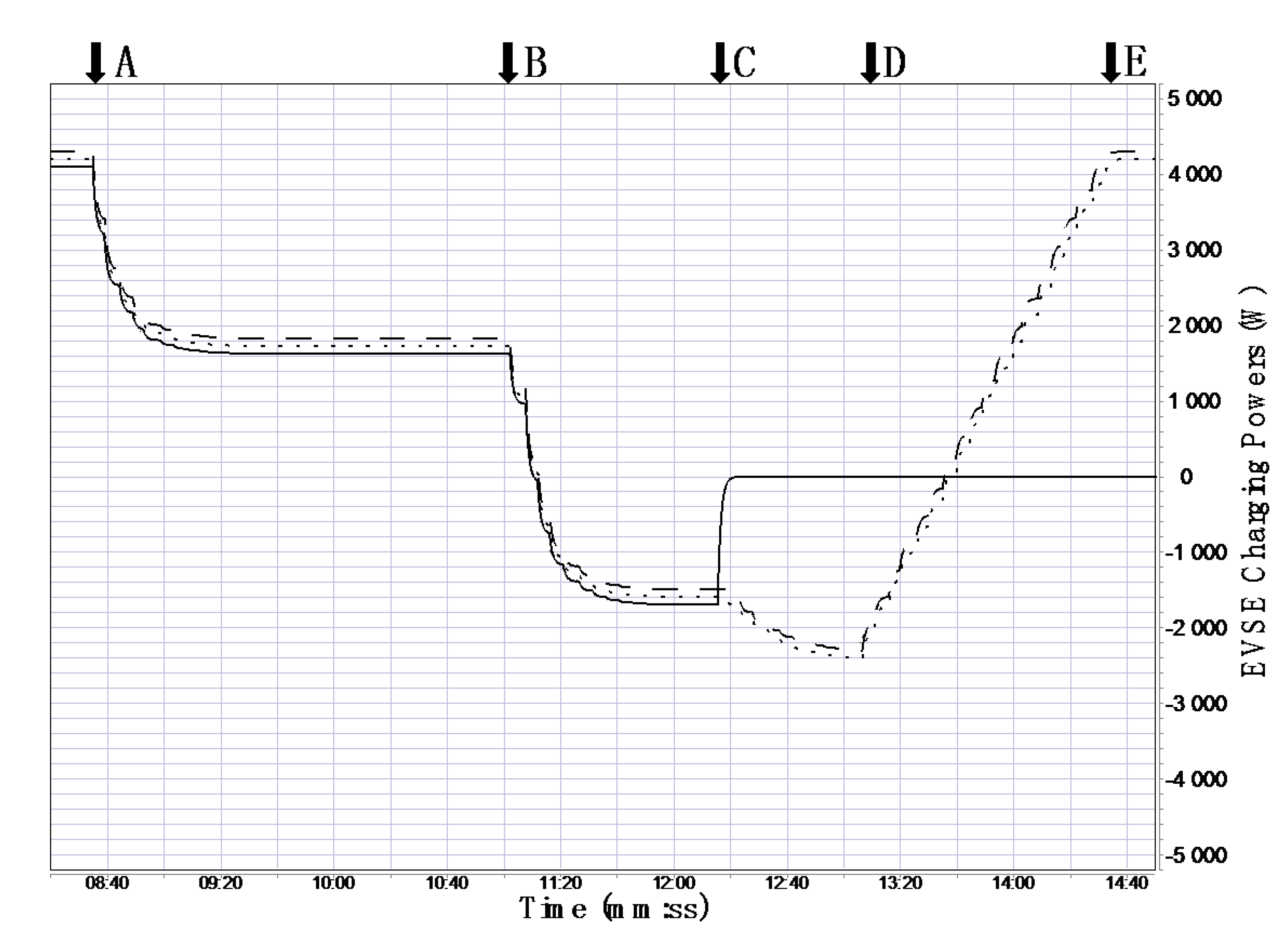
4.2 Initial State and Voltage Drop
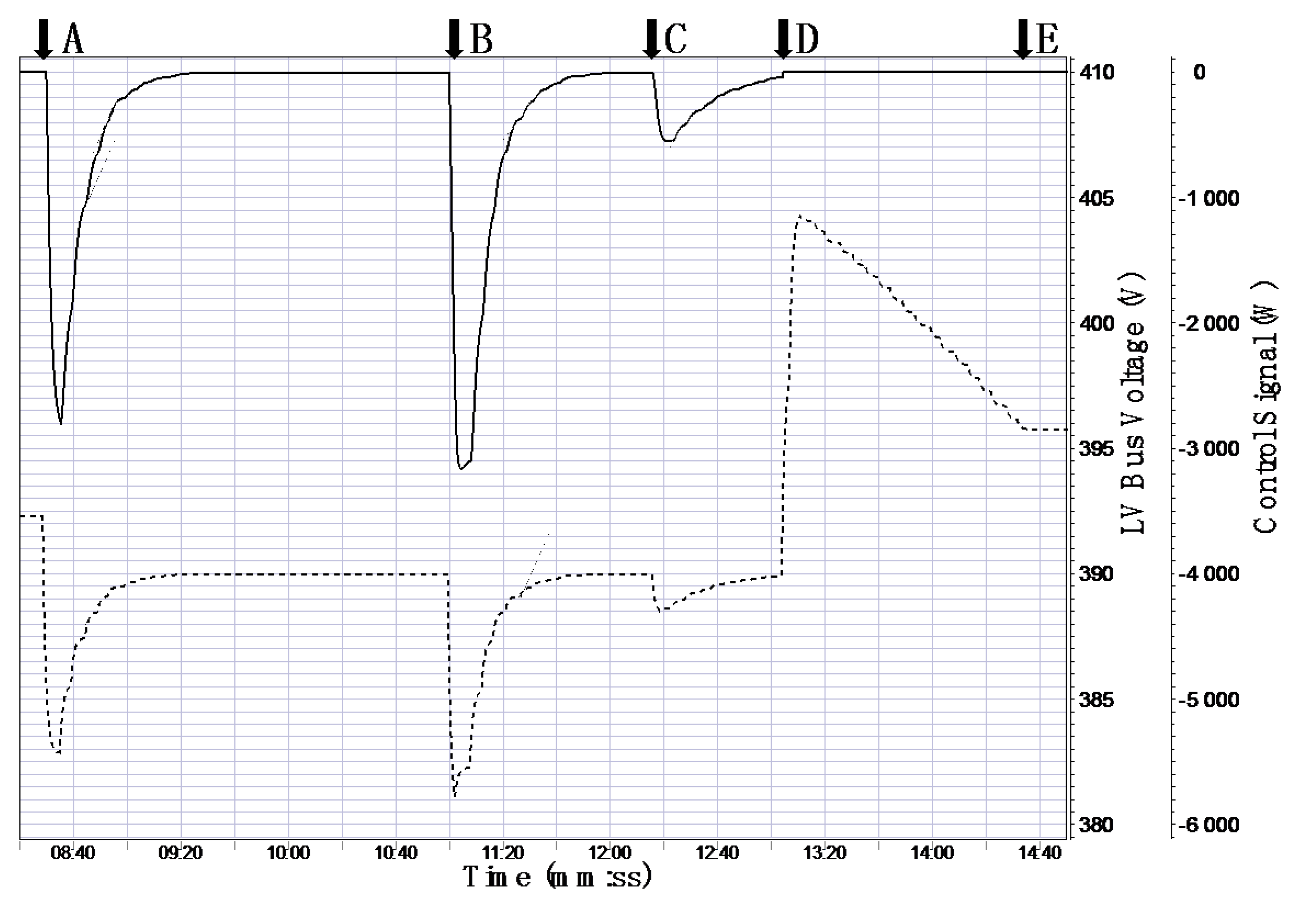

4.3 Disconnecting an EV and Autonomous Voltage Ramp-Up
5. Discussion
5.1 Approach
5.2 Simulation System
5.3 Results of the Simulation Steps
5.4 Future Work
6. Conclusion
Acknowledgments
Authors Contributions
Conflicts of Interest
References
- Kempton, W.; Tomić, J. Vehicle-to-grid power fundamentals: Calculating capacity and net revenue. J. Power Sources 2005, 144, 268–279. [Google Scholar] [CrossRef]
- Kempton, W.; Tomić, J. Vehicle-to-grid power implementation: From stabilizing the grid to supporting large-scale renewable energy. J. Power Sources 2005, 144, 280–294. [Google Scholar] [CrossRef]
- Rautiainen, A.; Markkula, J.; Repo, S.; Kulmala, A.; Jarventausta, P.; Vuorilehto, K. Plug-in vehicle ancillary services for a distribution network. In Proceedings of the 2013 8th International Conference and Exhibition Ecological Vehicles and Renewable Energies (EVER), Monte Carlo, Monaco, 27–30 March 2013; pp. 1–8.
- Shumei, C.; Xiaofei, L.; Dewen, T.; Qianfan, Z.; Liwei, S. The construction and simulation of V2G system in micro-grid. In Proceedings of the 2011 International Conference Electrical Machines and Systems (ICEMS), Beijing, China, 20–23 August 2013; pp. 1–4.
- Schuller, A.; Dietz, B.; Flath, C.M.; Weinhardt, C. Charging Strategies for Battery Electric Vehicles: Economic Benchmark and V2G Potential. IEEE Trans. Power Syst. 2014, 29, 2014–2022. [Google Scholar] [CrossRef]
- Park, C.; Lee, E.; Park, S. Link adaptation layer of HomePlug GreenPHY for V2G communication interface. In Proceedings of the 2012 18th Asia-Pacific Conference on Communications (APCC), Jeju Island, Korea, 15–17 October 2012; pp. 572–573.
- Mets, K.; Ojea, J.; Develder, C. Combining Power and Communication Network Simulation for Cost-Effective Smart Grid Analysis. IEEE Commun. Surv. Tutor. 2014, 16, 1771–1796. [Google Scholar] [CrossRef]
- OPNET modeler Commercial network simulator. Available online: http://www.opnet.com/ (accessed on 30 December 2014).
- NS-3. Network simulator. Available online: http://www.nsnam.org/ (accessed on 30 December 2014).
- OMNeT++ Library for building network simulator. Available online: http://www.omnetpp.org/ (accessed on 30 December 2014).
- PSCAD. Power systems simulation tool. Available online: https://hvdc.ca/pscad/ (accessed on 30 December 2014).
- Apros. Process simulation software. Available online: http://www.apros.fi (accessed on 30 December 2014).
- Yang, C.; Zhabelova, G.; Yang, C.; Vyatkin, V. Cosimulation Environment for Event-Driven Distributed Controls of Smart Grid. IEEE Trans. Ind. Inform. 2013, 9, 1423–1435. [Google Scholar] [CrossRef]
- Bruckner, C.; Swynnerton, B. A new architecture for hardware-in-the-loop test. Available online: http://www.rti.com/docs/ATZ_elektronik_HiL_Audi_en.pdf (accessed on 30 December 2014).
- Jeon, J.; Kim, J.; Kim, H.; Kim, S.; Cho, C.; Kim, J.; Ahn, J.; Nam, K. Development of Hardware In-the-Loop Simulation System for Testing Operation and Control Functions of Microgrid. IEEE Trans. Power Electron. 2010, 25, 2919–2929. [Google Scholar] [CrossRef]
- Latvakoski, J. Integration Test Automation of Embedded Telecommunication Software; VTT Publication 318: Espoo, Finland, 1997; p. 97. [Google Scholar]
- Donoghue, J.; Cruden, A.J. Whole system modelling of V2G power network control, communications and management. In Proceedings of the Electric Vehicle Symposium and Exhibition (EVS27), Barcelona, Spain, 17–20 November 2013; pp. 1–9.
- International Organization for Standardization. ISO/IEC DIS 15118-2: Road Vehicles—Vehicle-to-Grid Communication Interface—Part 2: Technical Protocol Description and Open Systems Interconnections (OSI) Layer Requirements; IOS: Geneva, Switzerland, September 2011. [Google Scholar]
- Electric Power Market. Available online: http://www.nordpoolspot.com/ (accessed on 30 December 2014).
- Buve, F.; McMahon, B. Open Charge Alliance: Open Charge Point Protocol 2.0-Interface Description between Charge Point and Central System, Version 2.0.0; Available online: http://www.openchargealliance.org/sites/default/files/OCPP%202.0%20Release%20Candidate%202.pdf (accessed on 10 July 2015).
- Mahnke, W.; Leitner, S.; Damm, M. OPC Unified Architecture; Springer Berlin Heidelberg: Berlin, Germany, 2009; p. 339. [Google Scholar]
- Latvakoski, J.; Honka, H. Time simulation methods for testing protocol software embedded in communicating systems. In Testing of Communicating Systems, Methods and Applications, Proceedings of the IFIP TC6 12th International Workshop on Testing Communicating Systems, Budabest, Hungary, 1–3 September 1999; Kluwer Academic Publishers: Boston, MA, USA, 1999; pp. 379–394. [Google Scholar]
© 2015 by the authors; licensee MDPI, Basel, Switzerland. This article is an open access article distributed under the terms and conditions of the Creative Commons Attribution license (http://creativecommons.org/licenses/by/4.0/).
Share and Cite
Latvakoski, J.; Mäki, K.; Ronkainen, J.; Julku, J.; Koivusaari, J. Simulation-Based Approach for Studying the Balancing of Local Smart Grids with Electric Vehicle Batteries. Systems 2015, 3, 81-108. https://doi.org/10.3390/systems3030081
Latvakoski J, Mäki K, Ronkainen J, Julku J, Koivusaari J. Simulation-Based Approach for Studying the Balancing of Local Smart Grids with Electric Vehicle Batteries. Systems. 2015; 3(3):81-108. https://doi.org/10.3390/systems3030081
Chicago/Turabian StyleLatvakoski, Juhani, Kari Mäki, Jussi Ronkainen, Jukka Julku, and Jani Koivusaari. 2015. "Simulation-Based Approach for Studying the Balancing of Local Smart Grids with Electric Vehicle Batteries" Systems 3, no. 3: 81-108. https://doi.org/10.3390/systems3030081
APA StyleLatvakoski, J., Mäki, K., Ronkainen, J., Julku, J., & Koivusaari, J. (2015). Simulation-Based Approach for Studying the Balancing of Local Smart Grids with Electric Vehicle Batteries. Systems, 3(3), 81-108. https://doi.org/10.3390/systems3030081