Article

4D BIM-Based Enriched Voxel Map for UAV Path Planning in Dynamic Construction Environments

1
School of Civil Engineering, Iran University of Science and Technology, Tehran 16846-13114, Iran
2
School of Engineering, University of Greenwich, London SE10 9LS, UK
3
School of Architecture & Environmental Design, Iran University of Science and Technology, Tehran 16846-13114, Iran
4
School of Built Environment, University of Technology Sydney (UTS), Ultimo 2007, Australia
*
Author to whom correspondence should be addressed.
Systems 2025, 13(10), 917; https://doi.org/10.3390/systems13100917
Submission received: 25 August 2025 / Revised: 24 September 2025 / Accepted: 16 October 2025 / Published: 18 October 2025

Abstract

Unmanned Aerial Vehicles (UAVs) are increasingly integral to construction site management, supporting monitoring, inspection, and data collection tasks. Effective UAV path planning is essential for maximizing operational efficiency, particularly in complex and dynamic construction environments. While previous BIM-based approaches have explored representation models such as space graphs, grid patterns, and voxel models, each has limitations. Space graphs, though common, rely on predefined spatial spaces, making them less suitable for projects still under construction. Voxel-based methods, considered well-suited for 3D indoor navigation, suffer from three key challenges: (1) a disconnect between the BIM and voxel models, limiting data integration; (2) the computational cost and time required for voxelization, hindering real-time application; and (3) inadequate support for 4D BIM integration during active construction phases. This research introduces a novel framework that bridges the BIM–voxel gap via an enriched voxel map, eliminates the need for repeated voxelization, and incorporates 4D BIM and additional model data such as defined workspaces and safety buffers around fragile components. The framework’s effectiveness is demonstrated through path planning simulations on BIM models from two real-world construction projects under varying scenarios. Results indicate that the enriched voxel map successfully creates a connection between BIM model and voxel model, while covering every timestamp of the project and element attributes during path planning without requiring additional voxel map creation.

1. Introduction

Unmanned Aerial Vehicles (UAVs) have significantly transformed various industries by providing productive solutions for data collection, inspection, and monitoring [1,2,3]. Their ability to navigate complex environments with minimum operator involvement has resulted in widespread adoption of them in agriculture [4], surveying, disaster response [5], and infrastructure inspection [6]. While UAVs have been widely used in outdoor applications, their potential in indoor environments, particularly in the construction industry, has attracted growing attention [7] due to the need for precise and efficient monitoring of construction progress [8], safety assessments [9], and resource management [10].
Despite their advantages, most drones are still operated by humans, making them susceptible to mistakes, labor-intensive, and less effective in complex settings [11]. Relying on manual navigation restricts the potential to fully utilize the capabilities of UAVs, as operators may struggle with line-of-sight constraints, real-time decision-making, and optimal route planning in congested spaces [12]. The main obstacle in employing drones for indoor applications is the requirement for developing an automated 3D path planning system that could efficiently navigate through dynamic construction sites [13]. In contrast to outdoor path planning, where GPS-based navigation works well, indoor environments necessitate more sophisticated localization and mapping methods to guarantee accurate and obstacle-free drone navigation [14].
Traditional approaches mainly concentrate on predefined environments with well-established spatial boundaries for drone path finding. These approaches often include creating space graphs, utilizing point-cloud navigation, or implementing grid-based methods to determine optimal paths [15]. However, these boundaries are constantly changing throughout the construction process, making conventional methods less effective. Dynamic obstacles such as scaffolding, temporary structures, and shifting materials create an ever-changing environment that complicates traditional path planning algorithms [16].
Building information modeling (BIM) is reshaping the landscape of architecture, engineering, and construction with a new paradigm for project design and management, offering comprehensive digital representations of buildings [17]. BIM provides rich geometric, semantic, and topological data that can enhance drone path planning by offering precise spatial information [18]. It allows for integrating material properties, construction schedules, and spatial relationships, enabling a holistic view of the building process [19]. However, most previous research has focused on BIM-based path planning in entirely constructed environments, overlooking the dynamic nature of construction sites and the need for continuous updates in navigational data [20].
To address this gap, this study proposes an innovative framework integrating 4D BIM with voxel-based navigation models to facilitate automated 3D indoor UAV path planning during construction. This approach ensures real-time adaptability to construction progress by incorporating temporal data into voxel models, enabling UAVs to navigate in partially built structures efficiently. The proposed methodology maintains a strong connection between the BIM model and the path finding environment, ensuring minimal information loss during data transformation. Additionally, it allows for the dynamic adjustment of navigation routes in response to site changes, thereby improving drone efficiency and operational safety.
This research demonstrates how a 4D voxel-based approach can optimize drone navigation by considering dynamic construction timelines, safety constraints, and workspace requirements. Integrating time-dependent data into navigation models enables UAVs to make informed decisions regarding their flight paths, avoiding hazards while maximizing efficiency. The results indicate that this framework effectively determines optimal flight paths, updates navigation routes in response to project changes, and enhances the overall efficiency of UAV deployment in construction environments. Furthermore, accounting for real-time changes in construction conditions reduces the risk of collisions and improves UAV autonomy.
This paper is structured as follows. Section 2 provides a review of the relevant literature, including the application of UAVs in construction projects (Section 2.1), existing path planning approaches (Section 2.2), and BIM-based UAV navigation (Section 2.3). The section concludes by identifying key research gaps. Section 3 outlines the research methodology, which is developed around the proposed framework. This framework comprises three main components: the voxelization process (Section 3.1), voxel model creation (Section 3.2), and voxel map generation and enrichment (Section 3.3). Section 4 presents the validation of the framework through its application to two real construction project models under varying site conditions. The results of this validation are analyzed and discussed in Section 5. Finally, Section 6 concludes this paper by summarizing the objectives, findings, and limitations of this study and by suggesting potential directions for future research.

2. Literature Review

2.1. UAVs in Construction and Path Planning

The utilization of Unmanned Aerial Vehicles (UAVs) in construction has significantly increased due to their efficiency in data collection [21], site monitoring [22], and safety inspections [23]. UAVs enable real-time visualization of construction progress, empowering project managers to make informed decisions. Nwaogu et al. [24] and de Melo et al. [25] have shown that UAVs enhance accuracy in construction site surveys and structural assessments, reducing manual labor and human error. However, one of the key challenges in UAV applications within indoor construction environments is the lack of effective autonomous path planning mechanisms that can navigate dynamic and evolving spaces [26].
The need for autonomous UAV path planning arises due to the complexity of construction sites, where obstacles such as scaffolding, machinery, and moving workers create highly dynamic conditions [6]. UAVs must be capable of adapting to these changes in real time to ensure efficient operation. Mourtzis et al. [27] explored machine learning and artificial intelligence-based navigation methods that allow UAVs to optimize their routes based on environmental conditions. However, these approaches typically demand large datasets and significant computational power, making their practical implementation challenging in real-time construction environments.

2.2. Traditional Path Planning Approaches

Based on the path planning environment, articles can be classified as non-model-based for unknown environments and model-based for known environments with a predesigned model [28], as shown in Figure 1. The latter focuses primarily on vehicle sensors for exploring and mapping unstructured and unknown environments, like 3D object reconstruction [29] and environment exploration [30]. At the same time, model-based approaches utilize pre-existing models to a certain degree. For instance, Gao et al. [31] introduced a technique that converts paths guided by humans in an existing model into drone routes that match in topology, following a teach-and-repeat process. While this method increased interactions between humans and computers, it only attained partial automation.
Previous model-based studies have focused on two primary approaches for UAV path planning: geometry-based [32] and network-based [33]. Network-based models mainly map the environment into a graph, where nodes correspond to indoor areas, while edges denote the distance along pathways connecting them. This model is primarily used for path planning in large construction sites because each graph node can define any space.
Space graph-based models use predefined spatial relationships between building elements to generate navigation paths. This method is effective in entirely constructed environments but fails in dynamic construction sites where structures continuously change [34]. A widely used graph-based method is the visibility graph [35], in which nodes denote spatial corners and the perimeters of obstacles or passageways (e.g., doors), while edges link nodes that have direct lines of sight to one another. Visibility graphs use direct line-of-sight connections between navigable points, reducing computational complexity but struggling with dynamic obstacles [36]. The second method is the Voronoi graph [37], comprising nodes positioned at the farthest possible distance from surrounding obstacles. These nodes are interconnected with edges that maintain a safe margin from all obstacles.
On the other hand, geometry-based models are commonly used in complex environments like 3D indoor navigation, where a more accurate representation of the environment’s shape and features is required. This model discretizes internal spaces into predefined shaped cells to characterize the interior environments and discriminate against obstacles, which provides the ability to capture adjacency between neighboring cells [38]. The most popular geometry-based models are mesh models, point cloud models, and voxel-based models.
In a mesh-based representation [39], an object’s surface is depicted using a series of triangular or quadrilateral facets. This approach effectively captures intricate details, such as sharp edges, and allows path planning algorithms to process them efficiently. Additionally, mesh-based models enable precise calculations of distances and areas, which are essential for path planning algorithms that depend on distance metrics to determine optimal routes. However, this representation is not well-suited for depicting an object’s interior, and the process of generating a mesh can be computationally intensive.
Point cloud-based representation [40] represents an object as a collection of 3D points, making it well-suited for capturing complex geometries like holes and curved surfaces while effectively depicting objects’ exterior and interior. Point cloud models often require less storage and computational resources than other model representations, such as meshes or voxel grids. However, they are prone to noise, outliers, and missing data, necessitating additional processing for accurate utilization. Notably, point cloud models can be readily converted into other representations, such as voxel grids or meshes, depending on the needs of a specific path planning algorithm. While effective in precise mapping, this method requires extensive computational resources and external software integration [41].
Voxel-based models segment the environment into discrete, navigable units, allowing for flexible path planning even in dynamic settings [42]. This model efficiently represents space using discrete elements, assigning binary values (occupied or free) to each voxel. This representation aids quick collision detection and path computation but may demand high computational resources and lack precision for sharp edges or thin structures.
According to the voxelization approach, models are generally divided into fixed-size and adaptive voxel models [43]. The fixed-size voxel model divides the space into uniform, non-overlapping voxel units of equal dimensions. In contrast, adaptive voxel models, such as the octree and LEGO-based structures [43], use variable voxel sizes to better represent spatial complexity. The octree model organizes similar voxels under parent nodes, which helps to reduce data volume [44]. Although this method maintains consistent voxel shapes, it typically increases computational time for path planning when domain operations are involved. On the other hand, LEGO-based voxel models offer a more detailed representation of indoor environments than the octree method. Although they introduce variability in voxel size and shape, which can complicate processing [45], existing voxel models lack integration with 4D BIM, limiting their ability to update navigation paths in real time as construction progresses.
Some research has tried to integrate geometry-based and network-based approaches and define a hybrid model. Zhou et al. [46] used the BIM model to create a grid-based map. By implementing the image thinning theory on the provided grid-based map, a topological map was generated. The combination of the created grid-based map and the generated topological map formed their proposed hybrid model. In another study Xie et al. [47] simulate pedestrian evacuation by identifying indoor navigable space based on various types of motions and creating a voxel model for path finding in the determined spaces.

The Role of Voxel Mapping in UAV Path Planning

Voxel-based modeling has proven effective in representing complex 3D environments for navigation purposes. Unlike traditional space graph and point-cloud methods, voxel models offer a structured approach to spatial segmentation, making them highly suitable for dynamic path planning. Recent advancements in voxel-based navigation have focused on enhancing computational efficiency and real-time adaptability [48]. However, existing models often operate in static environments and do not account for the dynamic nature of construction sites.
The introduction of voxel mapping addresses this gap by integrating time-dependent construction data into UAV path planning. UAVs can dynamically adjust their flight paths based on real-time site conditions by associating voxel elements with specific construction phases. This approach reduces the risk of navigation errors and enhances UAV efficiency in monitoring evolving construction sites. Moreover, 4D voxel models directly link BIM elements, ensuring minimal data loss during transformation processes.
Using voxel maps also enables UAVs to perform multi-target path planning, optimizing their flight paths across multiple waypoints. This is particularly useful in large-scale construction projects where drones need to inspect several areas in a single flight. By incorporating heuristics and swarm intelligence algorithms, UAVs can efficiently navigate complex environments while minimizing energy consumption.

2.3. BIM Integration in UAV Navigation

A detailed model of the building is essential to facilitate automatic path planning. This model must incorporate semantic, topological, and geometric attributes relevant to navigation, including spaces to traverse, obstacles such as walls, slabs, and columns, and pathways through these barriers, such as doors, stairs, ramps, elevators, windows, and escalators [49]. Several standardized models provide a more comprehensive representation of buildings compared to generic CAD models. Notably, building information models (BIMs) in the Industry Foundation Classes (IFC) format and Geospatial Information System (GIS) models, such as CityGML and IndoorGML, not only offer precise 3D geometric data but also include semantic information that defines building components and their relationships [50].
The IFC format, a globally recognized standard for BIM (ISO 16739), developed by BuildingSmart, supports the entire lifecycle of a building, from design to deconstruction. It enables storing advanced geometric and semantic data related to building components [51]. In IFC, physical elements within a building are classified into well-defined semantic entities (e.g., walls as IfcWall, slabs as IfcSlab, and spaces as IfcSpace), alongside their 3D geometry, attributes, and detailed specifications stored within property sets (P-Sets). Furthermore, IFC provides a framework for defining spatial relationships, aggregation, and composition among various building elements, ensuring a comprehensive representation of indoor environments [52].
Building information modeling (BIM) has been extensively used in UAV navigation studies, offering a comprehensive representation of construction environments. BIM provides rich datasets, including geometric, semantic, and topological information, facilitating efficient path planning [53]. The integration of BIM with UAVs primarily follows two data exchange models: BIM-to-drone and drone-to-BIM approaches. The BIM-to-drone model defines optimal flight paths based on pre-existing data [54], while the drone-to-BIM model incorporates real-time UAV data into BIM for continuous updates [55].
Recent research has focused on extracting and managing geometric and semantic information from IFC models for various applications in the AEC industry, including quantity takeoff [56], cost estimation [57], and rule-based compliance checking [58]. In the domain of indoor path planning, several BIM-based approaches have been developed to generate navigation models. Notable examples include InSightBIM-Evacuation [59], which ensures compliance with evacuation regulations, and EvacuSafe [60], which integrates fire simulation and risk assessment to evaluate building safety. BIM-Game [61] also combines building information modeling with interactive gaming for real-time architectural visualization.
Path planning methods leveraging IFC data have also been explored, such as Lin et al.’s approach [62], which extracts building information, maps it onto a planar grid, and applies the fast-marching method (FMM) algorithm for shortest-path calculations. Similarly, Taneja et al. [63] proposed algorithms to generate different navigation models, including centerline networks, metric networks, and 2D floor grids. Other advancements include BIM-based augmented reality applications for maintenance navigation [64], variable density networks (VDNs) for emergency egress [65], and computational methods for measuring walking distances within buildings [66]. Moreover, beacon deployment algorithms integrated with BIM have been developed [67] to aid in emergency response and occupant localization. These advancements highlight the growing role of BIM and IFC models in enhancing indoor navigation and safety, demonstrating their potential for future applications in smart buildings and emergency management.
Although BIM-based path planning has been widely explored for fully constructed buildings, research on its application in active construction sites remains limited. Studies have highlighted the challenge of maintaining real-time updates within BIM models to reflect changing site conditions [68]. Addressing this limitation requires the integration of 4D BIM, which incorporates construction timelines into spatial models, providing a more adaptive and responsive path planning framework. Chen et al. [69] have shown the role of BIM in construction safety, using UAVs to identify hazardous zones and potential risks. Drones with thermal imaging and LiDAR sensors can enhance construction site monitoring by detecting unsafe conditions. When integrated with BIM, these UAVs can provide real-time updates to project managers, ensuring proactive decision-making and hazard mitigation.

Research Gap and Contribution

Despite extensive BIM-based UAV path planning research, significant gaps remain in integrating BIM with autonomous navigation systems. Traditional path planning methods are limited in handling dynamic construction environments, leading to inefficiencies in UAV operation. Existing voxel-based models lack temporal adaptability, restricting their applicability in real-world construction projects.
As shown in Figure 2, the path planning is executed by voxelizing a 3D BIM model. Several problems with the traditional path planning method need to be mentioned. First, the voxelization process is commonly implemented by extracting an OBJ file from a BIM model, which leads to missing BIM data and only pure geometry information availability. The second problem is that there is a need for a second piece of software to read the OBJ file and create a voxel model. The last one is that creating a voxel model from a BIM model is time-consuming, making the repetition unreasonable for each path finding scenario. These reasons compel most of the path planning research to mention the time of finding a path from the prepared voxel map as the path finding time.
To fulfill these gaps, this research proposes a framework for creating a voxel model using a plugin inside the Revit software and enriching a voxel map using BIM model data consisting of elements’ geometry, safety issues, and construction details like schedule and workspaces. This process will eliminate the requirement for voxelizing the BIM model for each path planning scenario. Moreover, this research proposes a novel 4D voxel-based framework that enhances UAV navigation in active construction sites. The proposed approach enables real-time path adjustments by leveraging BIM’s temporal data, improving safety and efficiency. The findings from this study contribute to advancing UAV autonomy in construction monitoring, bridging the gap between BIM-driven modeling and practical UAV deployment in dynamic settings.

3. Method

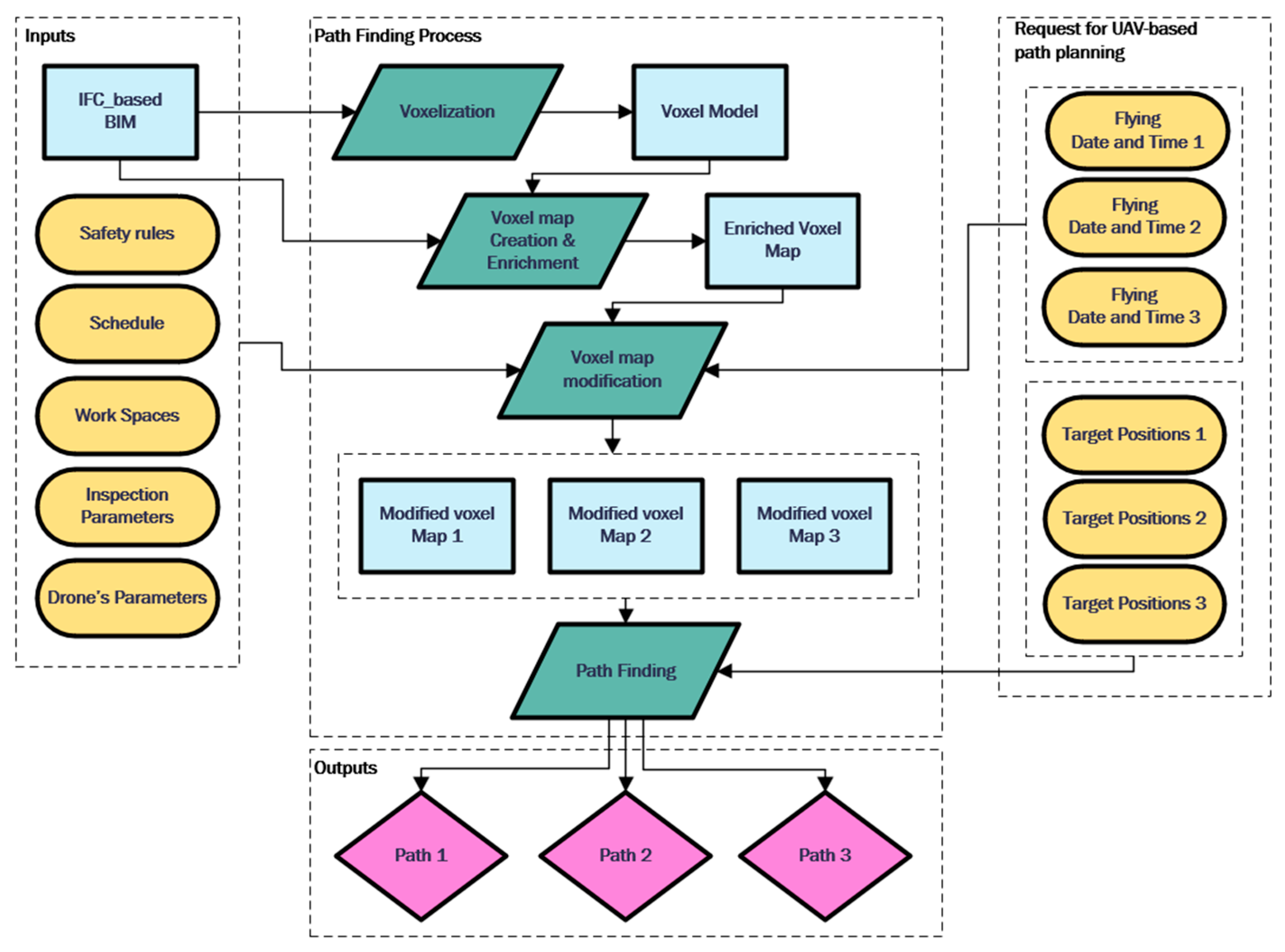
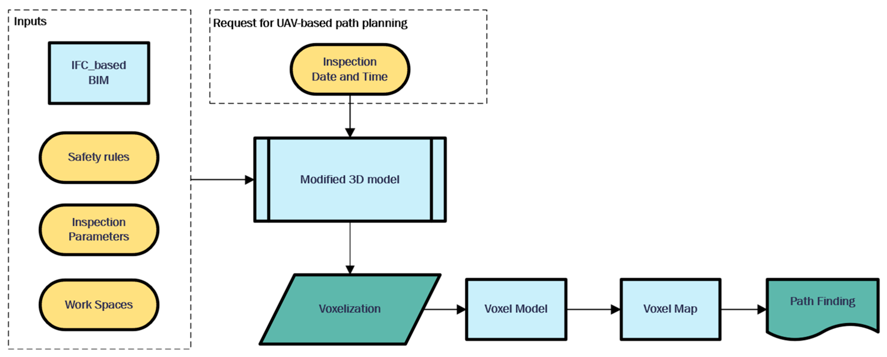
This section describes the detailed methodology of the proposed framework. The proposed framework is presented in Figure 3. The path planning consists of (1) voxelization, (2) voxel map enrichment, (3) voxel map modification considering site conditions, and (4) path finding, which are detailed in Section 3.1, Section 3.2, Section 3.3 and Section 3.4, respectively.
The primary objective of this research is to create a voxel map that can be used for path planning at various stages of the project, considering different scenarios of construction site circumstances, without requiring voxelization of the BIM model each time. To do this, an enriched voxel map is defined as a connection with each BIM model element using ElementIDs of the BIM model elements that intersect with voxel model cubes.

3.1. Voxelization

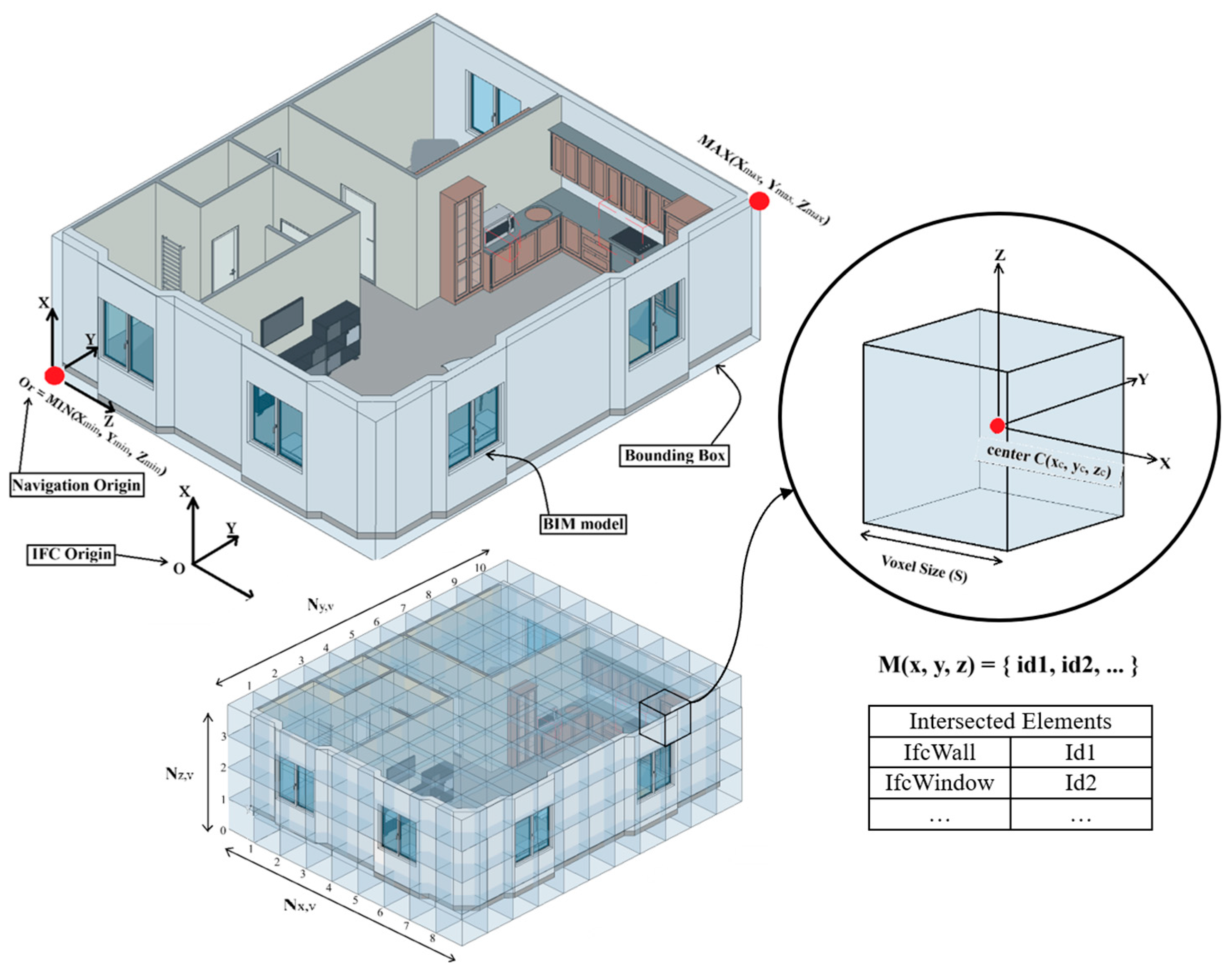
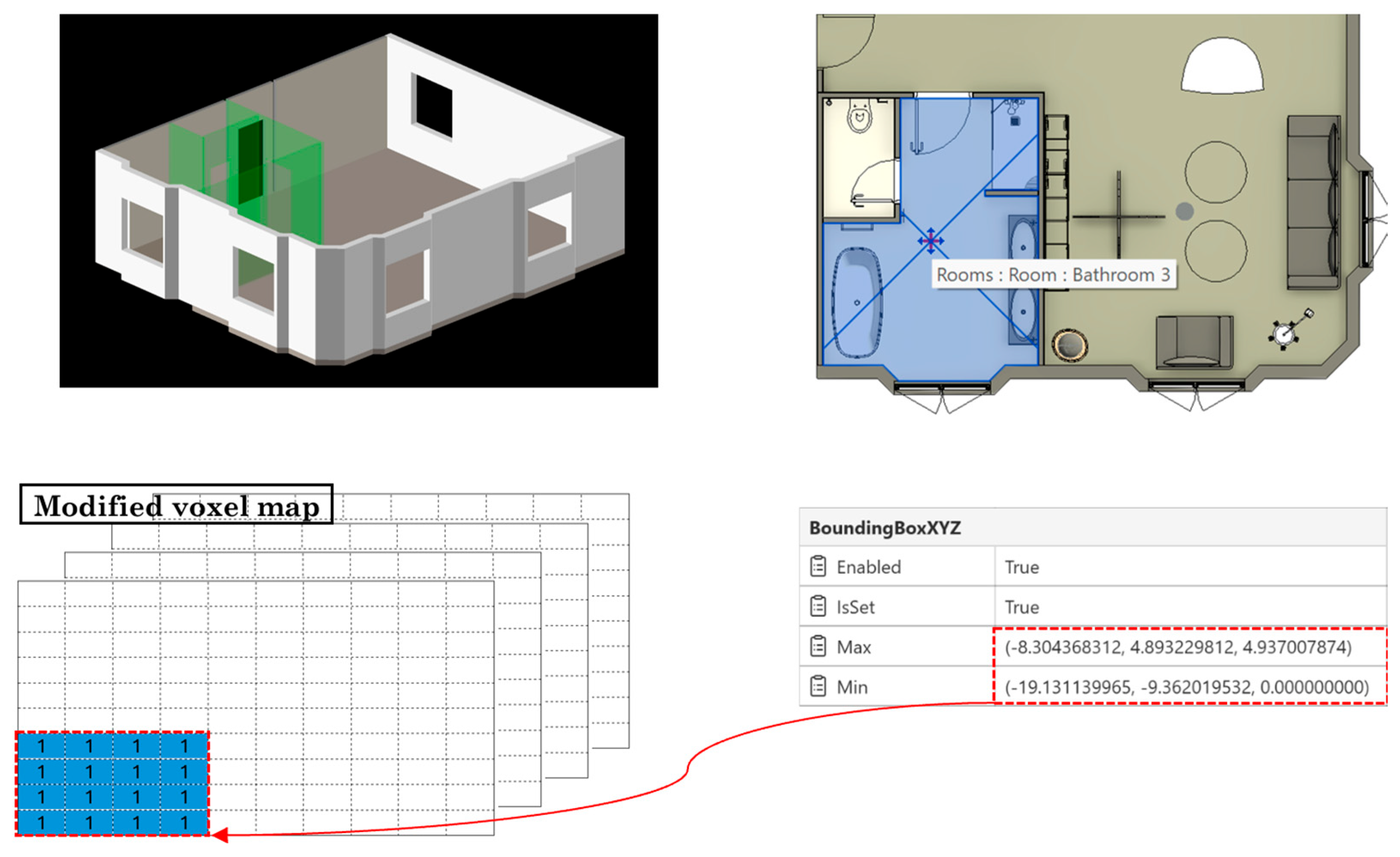
The proposed method divides the 3D model into non-overlapping voxels of fixed size, as shown in Figure 4. Each voxel represents the situation of a cubic space in terms of whether it is available for flying in. Two requirements for creating a voxel model are defining the navigable space boundary and determining the number of voxels in each direction, which are detailed in Section 3.1.1 and Section 3.1.2.

3.1.1. Navigable Space Boundary

The navigable space could be defined using the project’s bounding box, which is a 3D invisible rectangular that encloses entire project’s model elements, including their geometries in the 3D space. If the project bounding box is not determined precisely or is in use for other purposes, there should be another way to determine navigable space. This space could be retrieved using the minimum and maximum coordinates of the project elements. After collecting all the elements, the bounding boxes of the elements are extracted, and the minimum ( X m i n ,   Y m i n ,   Z m i n ) and maximum X m a x ,   Y m a x ,   Z m a x   coordinates of each bounding box are collected in two separate lists, called the ‘minimum list’ and the ‘maximum list’. The minimum coordination of the minimum list and the maximum coordination of the maximum list are the minimum and maximum coordination of the search space. The pseudo-code for determining the space boundary is represented in Algorithm 1.
Algorithm 1: DETERMINING SEARCH SPACE BOUNDARY
  INPUT: 3D BIM MODEL
  OUTPUT: THE NAVIGABLE SEARCH SPACE COORDINATION
1Collect all the elements
Let ref be the collection of all elements in the project document doc.
Let min_coords be the list of minimum coordinates of bounding boxes
Let max_coords be the list of maximum coordinates of bounding boxes
Let elements_list be the Filter of ref to include only element instances from the project (excluding element types).
2Extracting the bounding box of elements
For each element in elements_list:
   Let BB be the bounding box of elements.
3   Extract the minimum and maximum coordinates of bounding boxes
   Save the Min of the bounding box (lower-left-rear corner of the box) in min_coords
   Save the Max of the bounding box (upper-right-front corner of the box) in max_coords
4Determine search space coordinates
Select the minimum of the min_coords list the minimum coordination of navigable search space ( X m i n , Y m i n , Z m i n ) .
Select the maximum of the max_coords list as the maximum coordination of navigable search space X m a x , Y m a x , Z m a x .

3.1.2. Number of Voxels in Each Direction

Using the boundary search space, the limitations of voxel model coordination are determined as shown in Equation (1).
X m i n < x v < X m a x Y m i n < y v < Y m a x Z m i n < z v < Z m a x
where x v , y v and z v are the coordination of the voxel’s center along axes X, Y and Z.
Based on the voxel size (S) and the search space boundary dimensions, the number of voxels (N) along the axes are shown in Equation (2), which are the dimensions of the matrix M.
N x , v =   X m a x X m i n   S N y , v =   Y m a x Y m i n   S N z , v =   Z m a x Z m i n   S
where N x , v , N y , v , N z , v are the number of voxels along axes X , Y and Z .

3.1.3. Voxel Model Creation

The voxel model cube’s center is presented in Equation (3). Considering the voxel size (S), a cube with dimension equal to voxel size is placed in each coordinate according to the relations defined in Equations (3) and (4). The intersection between the solid geometry of elements in the BIM model and the placed cube is checked using ElementIntersectsElementFilter. If there is any intersection, the cube is omitted from the voxel model, and if not, the cube is stored. The process is repeated for the next coordinate until all coordinates reach the project’s bounding box boundary.
x c = X m i n + i + 0.5 S y c = Y m i n + j + 0.5 S z c = Z m i n + k + 0.5 S
where i, j, and k are ∈ Z and
0 i N x , v 0 j N y , v 0 k N z , v

3.2. Voxel Map

This research proposed a 3D matrix (M) as a connection between the BIM and voxel models. This matrix represents a voxel model, so first, based on the created voxel model that is described in Section 2.2, a voxel map is generated, which is detailed in Section 3.2.1. For establishing a relation between this voxel map and the BIM model, the voxel map should be enriched, which is detailed in Section 3.2.2.

3.2.1. Voxel Map Definition

The matrix dimensions represent the number of voxels in each direction of the search space. The matrix dimensions are, respectively, equal to N x , v ,   N y , v and N z , v . The relationship between the voxel model’s cube center and the index of the voxel map matrix is equal to Equation (5). Moreover, the relationships between the index ( i ,   j ,   k ) of the matrix M and any location in the project x ,   y ,   z , which shows the cube number in the voxel model in that direction, are as follows:
i = [     x X m i n   S ] j = [     y Y m i n   S ] k = [     z Z m i n   S ]
where the ‘min’ function returns the minimum integer of the value.

3.2.2. Voxel Map Enrichment

The matrix M represents the voxel model in a 3D matrix shape, so each item of the matrix should represent a cube in the voxel model. On the other hand, the type of data stored in the matrix should help maintain the relationship between the BIM model and the voxel model. Unlike previous studies that filled the matrix with ‘zero’ and ‘one’, which isa representation of situations like obstacles and free passes, in this research the matrix items are defined as a list of integers that are Element IDs of those model elements, which have an intersection with the placed cube of the voxel model in that 3D coordination.
For each cube stored from Section 3.1.3, the output of ElementIntersectsElementFilter, which is the list of ElementIds of BIM model elements that have an intersection with the cube, is stored as a list in the defined matrix as M (i, j, k). This procedure will create a matrix as a voxel map with an implicit connection to the original BIM model using ElementIds of the BIM model’s entities, which will help retrieve any information from the original BIM model. The pseudocode for creating the voxel model and voxel map is shown in Algorithm 2.
Algorithm 2: VOXEL MODEL AND VOXEL MAP GENERATION
INPUT: 3D BIM MODEL, VOXEL SIZE(S)
OUTPUT: VOXEL MAP (VOXEL MODEL AND VOXEL MATRIX)
1
2Parse the BIM model and determine the search space bounding box (BB).
3Create a cube according to voxel size(S)
4Create matrix(M) according to Equation (2).
5Let elements_list be the Filter of ref to include only element instances from the project (excluding element types).
Extracting the bounding box of elements
6For i in range (0, Nx,v):
7 For j in range (0, Ny,v):
8 For k in range (0, Nz,v):
9 Place the cube according to Equation (4).
10 Find intersected elements with the cube using ElementIntersectElementFilter
11 If there is an intersection:
keep the cube in the voxel model
12 Store element IDs of intersected elements as a list in M (i, j, k)
13 If there is no intersection:
14 M (i, j, k) = 0
15 Delete the cube

3.3. Considering Site Condition in Voxel Map

Flying during the construction phase is different from flying during the operational phase. Certain conditions must be considered when flying within a construction site. To include these conditions in path planning, a matrix is first created based on the flight data. Then, different scenarios are applied as additional filters to this matrix, producing a modified voxel model that reflects the specific conditions of each scenario. This procedure avoids voxelizing the BIM model for each scenario, which was one of the weaknesses of the previous research.

3.3.1. Construction Timestamp

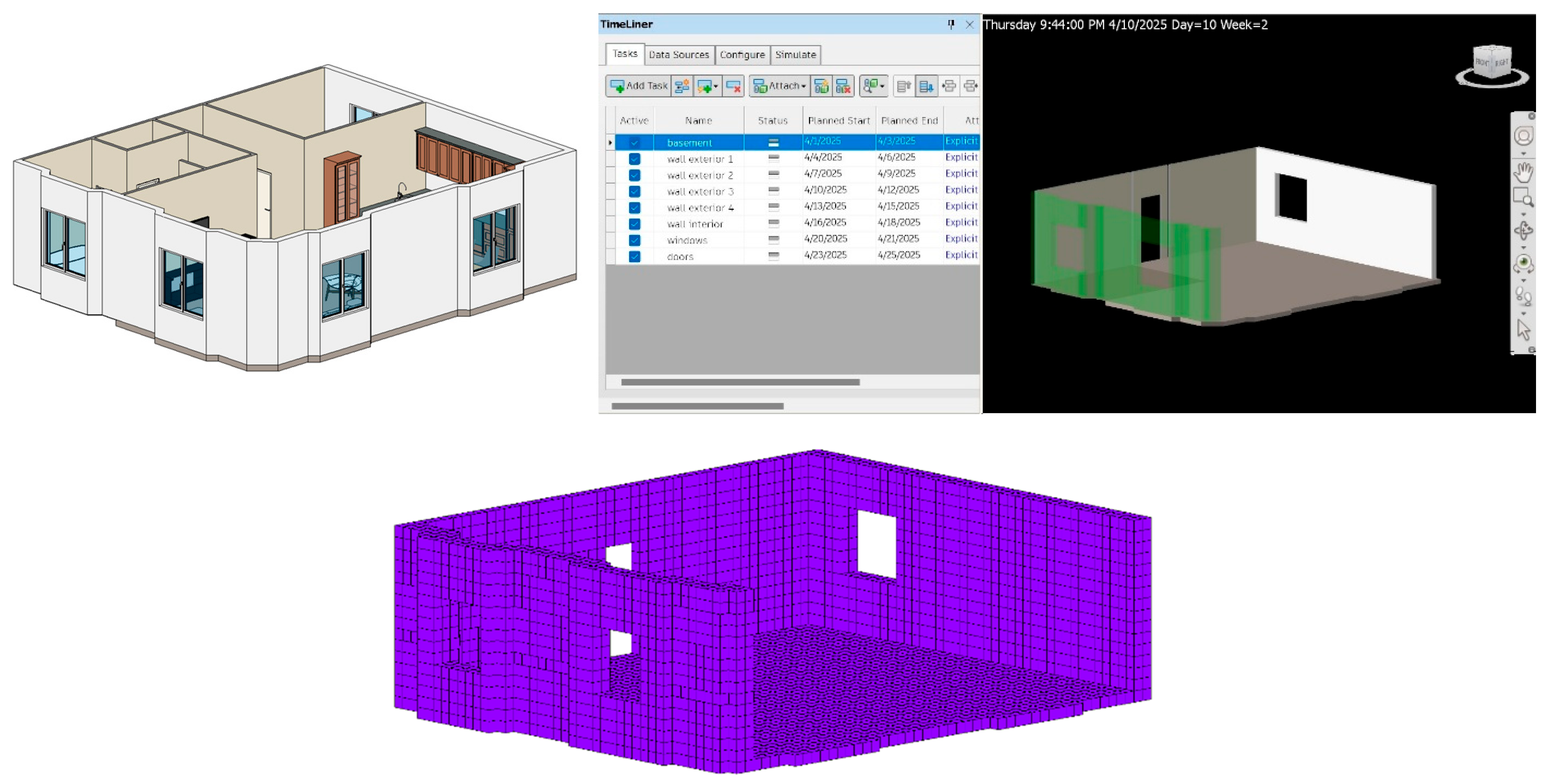
During the construction phase, certain elements are built according to a schedule. To find the optimal path before these elements are constructed, the corresponding cubes in the voxel model should be removed. The 4D BIM model needs to be voxelized using the same method as before (Figure 5), which can be a time-consuming process. Then, based on the created voxel model, path finding should be executed.
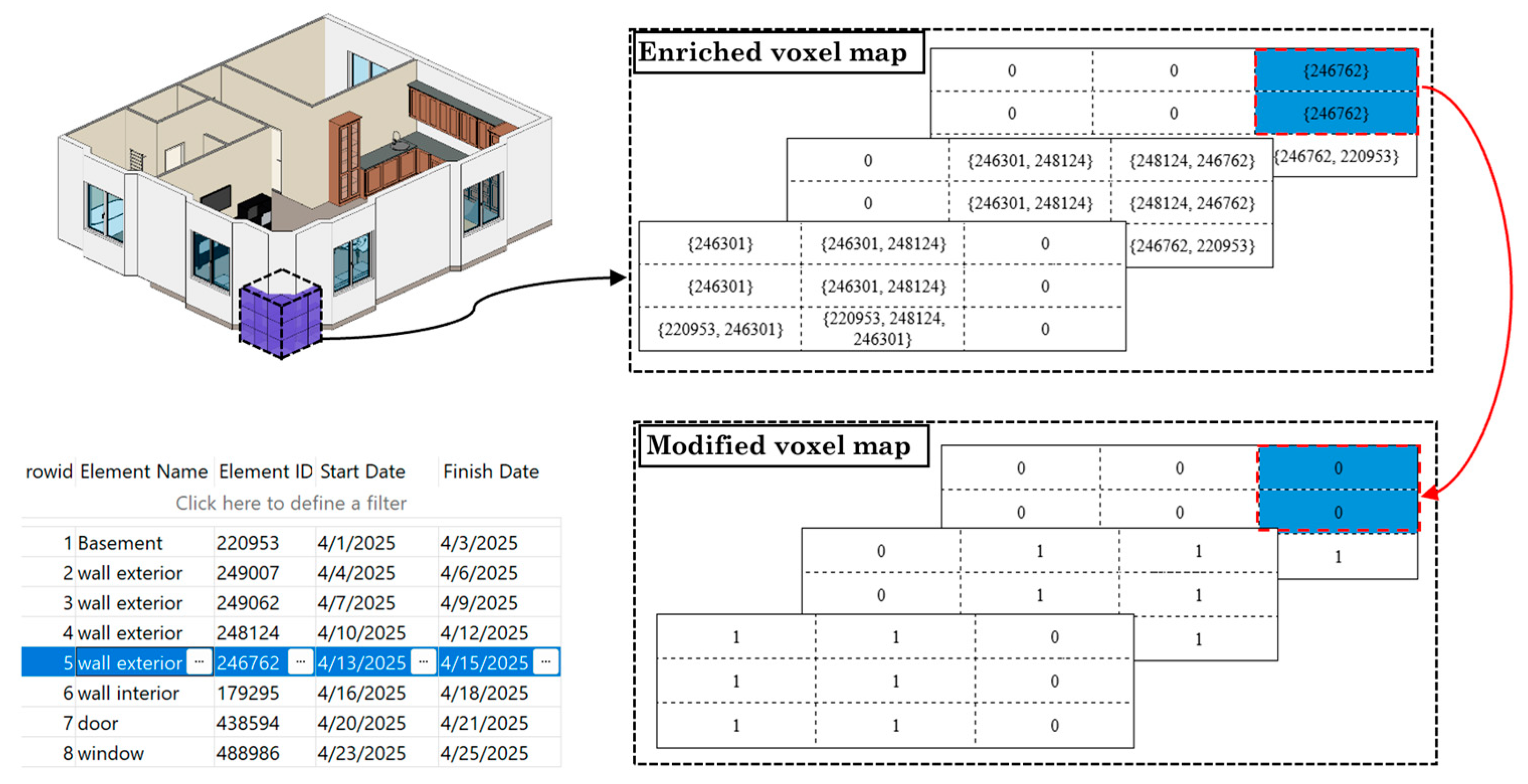
In the proposed framework based on the timeline, all elements’ data is extracted, and a modified voxel map is created using the enriched voxel map, as indicated in Figure 6. This process eliminates the requirement for voxelization of the model for each path planning request. To consider the construction time, each item on the enriched voxel map matrix has been investigated based on the flying date. For each item of the matrix with a list of element IDs, the start and end dates of the element are retrieved from the BIM model. Possible situations are as follows:
1.
If all the elements in the list have a start date after the flying date, it means that the related space is empty at that time and could be a part of the flying path.
2.
If even one of the elements has a start date before the flying date, the related space will be considered occupied and cannot be part of the flying path.

3.3.2. Workspaces

To accommodate workers’ spatial requirements, two additional filters will be incorporated into the voxel map. The first filter identifies elements whose construction period overlaps with the flying date, i.e., elements with a start date preceding and an end date following the flying date. For these elements, the associated predefined workspace bounding boxes are extracted from the BIM model. After converting to the matrix indices using Equation (2), the situation of the mentioned indices will change to occupied, as illustrated in Figure 7. Moreover, as a second filter, the modified voxel map matrix will retrieve and filter other workspaces that are not connected to any specific element but occurred between flying dates.

3.3.3. Safety Distance

The proposed voxel model algorithm voxelizes the pure geometry of the model, so safety issues additionally need to be considered in the voxel map. The safety distance can be separated into general and special safety distances. The general safety distance is the distance between the drone and all the elements of the project to ensure a secure flight. According to Freimuth & König [70], the minimum safety distance to construction project elements should be 35 cm. However, the special safety distance depends on the project’s elements. To compensate for additional safety concerns for elements like components with fragile materials (like glass) or pipes with harmful fluids, a special safety distance must be considered, which could be customized by users. Song et al. [71] considered a safety factor equal to 1.5 for fragile elements. Standards require that uncertainties be considered when determining protective clearances (ISO 12100) [72]. In engineering practice, non-critical design safety factors typically range from 1.5 to 2.0, and building codes commonly use 1.5 as a conventional minimum (IBC/ASCE) [73]. Therefore, we consider a conservative multiplier of 1.5–2.0 to the measured worst-case UAV positioning when defining exclusion zones for operations near fragile elements, which results in a 52.5–70 cm safety distance. For general safety distance, based on the predefined distance, the number of required voxels around all the voxels in the voxel model is calculated using Equation (6):
N D   =   min   ( safety distance / voxel size )
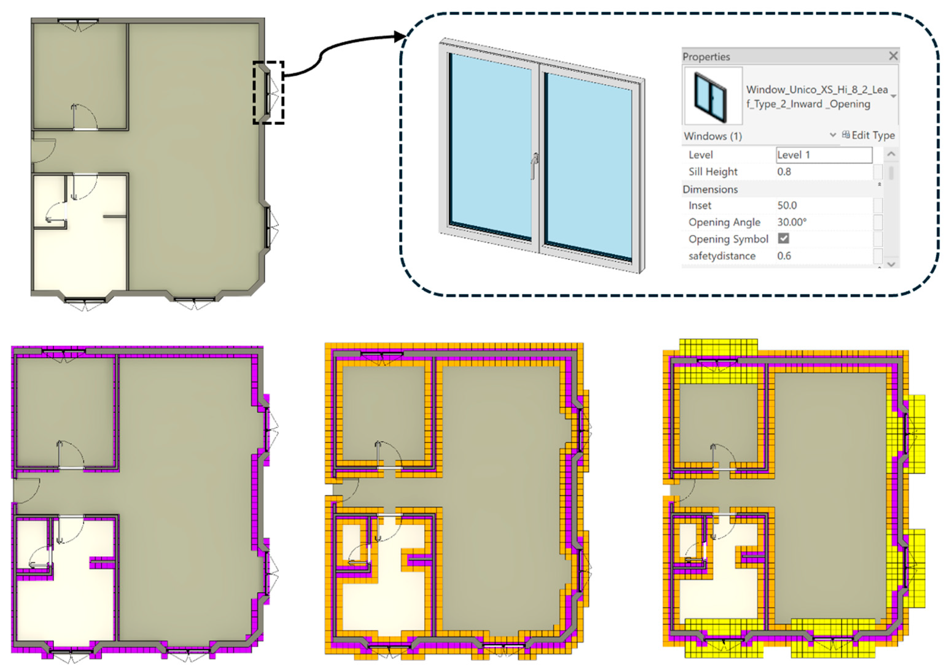
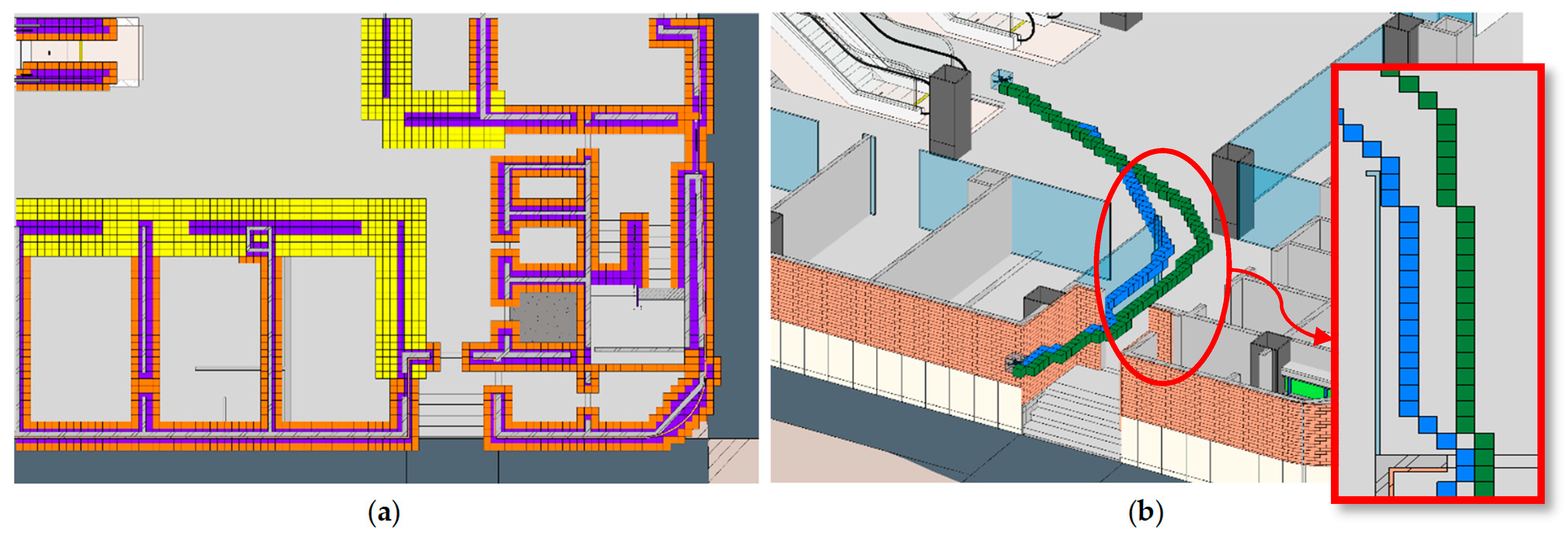
Based on the ND, around each item in the voxel map matrix, if it is zero, the ND item will change to one. However, for special equipment, ND will be calculated according to the required distance data extracted from the BIM model. Figure 8 represents the voxels related to walls (a), general safety cubes (b), and special safety cubes (c) related to windows as an element with fragile material that requires more safety distance.

3.4. Path Planning

Finding the path using the modified voxel map could have two scenarios: The first uses one start position and goal position, which requires a single path. On the other hand, finding the optimum path between multiple targets requires both prioritizing them and finding the optimum path between each pair of them.

3.4.1. Single Path (A*)

The A* algorithm has been adopted to search paths. The evaluation function is as shown in Equation (7):
F ( v )   =   g ( v )   + h ( v )
where g(v) represents the cost of the path from the current voxel (v) to the start point. h(v) represents the Euclidean distance between current voxel (v) and the target voxel (t), which is shown in the formula below:
d v i = i v i t d v j = j v j t d v k = k v k t h v = d v i 2 + d v j 2 + d v k 2  
where
d v i is the distance from current voxel (v) and the target voxel (t) in the X direction;
d v j is the distance from current voxel (v) and the target voxel (t) in the Y direction;
d v k is the distance from current voxel (v) and the target voxel (t) in the Z direction;
i ,   j ,   k are calculated using Equation (5) for voxel v.
According to the special relationship between voxels, as shown in Figure 9, the cost of each transmission between voxels is calculated using Equation (9):
D = S face based relationship 2 S edge based relationship 3 S point based relationship

3.4.2. Multi-Target Path (ACO + A*)

Finding a path between multiple targets, calculating the path costs between each pair of targets, and then considering all the possible paths that cover all the targets is a time-consuming process. Ramirez-Atencia et al. [74] and Bui et al. [75] proposed algorithms like GA, ACO, and so on to optimize the calculation path for multiple targets. In this research, the ACO algorithm has been used for several reasons. The ACO, a member of the swarm intelligence family, utilizes probability and is a successful approach in addressing the TSP problem. This algorithm draws inspiration from nature and has been validated through experimental studies. In tackling issues involving 50-, 75-, and 100-city scenarios, ACO has outperformed various metaheuristic methods such as genetic algorithms, evolutionary programming, and simulated annealing. Additionally, it produces the most optimal route. Unlike the GA algorithm, which proposes a complete genome and then calculates the cost of the genome, in ACO, the path is created step by step, considering the distances between each pair of positions. Equation (10) represents the standard transition probability formula for the ACO, and the ACO parameters are listed in Table 1. In this work, we fixed the ACO hyperparameters. These values were chosen to remain consistent with ranges commonly reported in the literature while avoiding the confounding effects of parameter re-tuning across experiments. For example, Hamledari et al. [76] applied ACO to UAV path planning with a pheromone weight of 1.2 and heuristic weight of 1 within their test, while the study by Banerjee and Modal [77] used an ant colony size of 50 ants with an evaporation rate of 0.05, demonstrating the acceptability of an evaporation rate between 0.05 and 0.1. Taken together, these references establish that our chosen settings lie well within typical practice, and fixing them across all trials isolates the effect of algorithmic modifications rather than parameter variations.
p i j k t = τ i j α t . η i j β u N i k t   τ i u α t . η i u β t i f   j     N i k t 0   i f   j     N i k t
where
p i j k t is the probability that ant k moves from node i to node j at time t.
τ i j α t is the pheromone intensity on edge (i, j) at time t.
η i j is the heuristic value (usually inverse of distance 1 d i j ).
α is a parameter controlling the influence of the pheromone trail.
β is a parameter controlling the influence of the heuristic value.
N i k t is a set of feasible nodes that ant k can visit from node i.
Table 1. ACO hyperparameters.
ParameterValue
pheromone exponential weight1.2
Heuristic exponential weight1
pheromone deposit coefficient1
evaporation rate0.05
initial pheromone1
Number of ants (population size)50
Maximum number of iterations150

4. Implementation

This section describes the proposed framework’s implementation details and validation techniques in two construction projects. The validation is limited to simulating various scenarios, and real-world UAV deployment remains for future works.

4.1. Experimental Setup

The software environment mainly includes the Microsoft Windows 11 × 64 system and Microsoft Visual Studio 2022. The hardware environment includes an Intel (R) Core (TM) i7-13700H 2.40 GHz CPU, a graphics processor called Intel® Iris® Xe, and 16 GB RAM.
The proposed method has been examined on two construction projects’ models at different timestamps. All the required data, modeling, voxelization, and path finding were executed using a developed plugin in Revit software. The plugin was developed for Autodesk Revit 2024 using the Revit API 2024. Implementation was carried out in Python version 3.12 via pyRevit within Microsoft Visual Studio 2022 using the NET Framework v4.0.30319. The project’s specifications are shown in Table 2.

4.2. Experimental Results and Discussion

Two construction projects’ BIM models were used to test the optimized path in various scenarios, considering different construction timestamps, drone sizes, safety distances, and precisions on both a single path for one start and one goal position and multiple paths among multiple target positions.

4.2.1. Validity Analysis of the Optimized Path Considering Different Start and Goal Positions

The voxel size was set to 0.5 for the two BIM models without additional voxels for the safety distance. The start and goal positions were obtained from both the indoors and outdoors of the model at a pre-determined timestamp of the project (fixed time in 4D model), as depicted in Table 3. For each model, two situations were considered. The first was the start and end position on the same floor, and the second was the start and end goal on different floors.
Figure 10 presents the path finding results and Figure 10a to Figure 10d are related to Table 3 ID (1) to (4), respectively. Specifically, Figure 10a,b illustrate the identified paths within the same floor and across different floors in Case Study (2), respectively. In contrast, Figure 10c,d depict the optimized paths generated for varying start and goal positions in Case Study (1).
The results demonstrate that the proposed framework effectively identifies the optimal path in both 2D and 3D scenarios. As shown in Figure 10b,d the proposed framework not only finds the optimum path from the stairs for transferring between floors but also avoids collision with the stair railing successfully. Comparing the length and runtime columns in Table 4 shows that the time required for path finding increases as the distance between the start and end points grows. Additionally, finding a path between two floors takes longer due to the presence of more obstacles and the extra calculations needed to determine a route through the connecting gateway.

4.2.2. Validity Analysis of the Optimized Path Considering Different Timestamps of the Projects (4D)

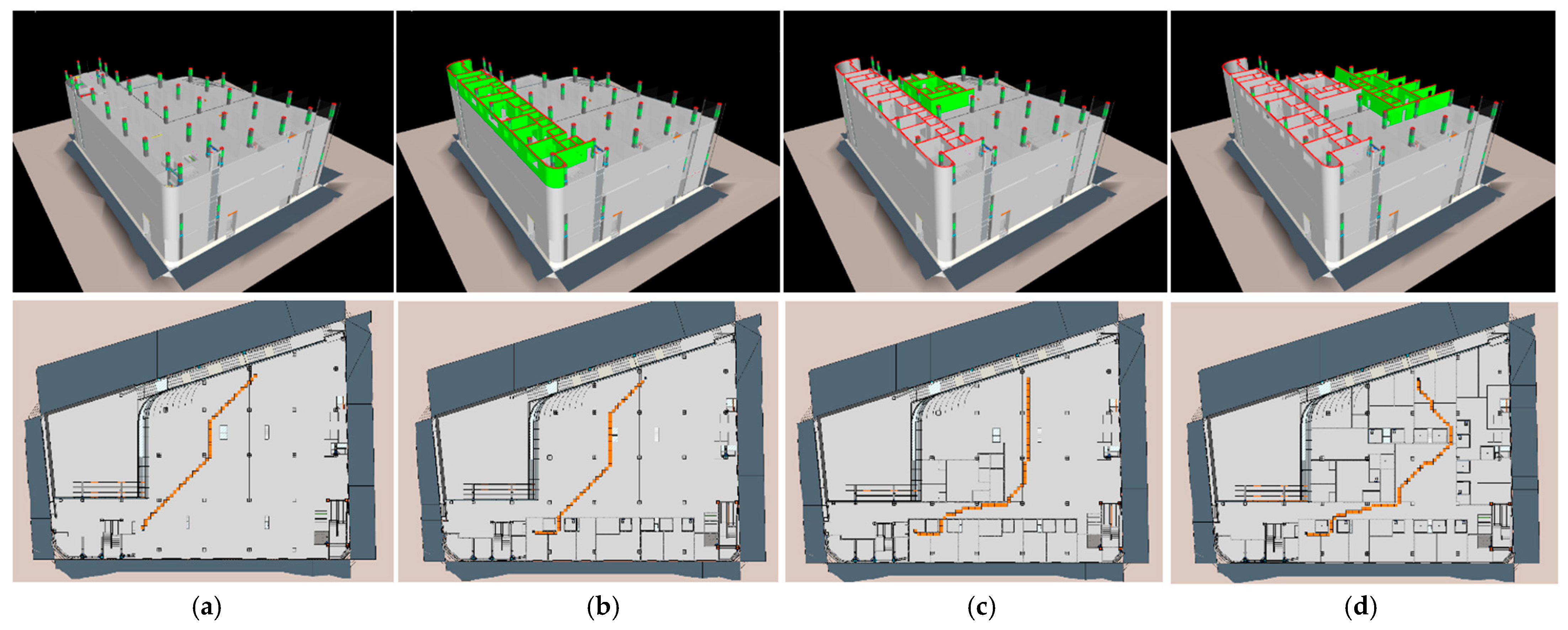
One of the most essential parts of this research is considering the construction timestamps in determining navigable space for indoor and outdoor projects. Different scenarios of the inspection date with a fixed voxel size and precision without additional safety distance were tested. Four key stages were tested: during the structural work of columns (Figure 11a), during the construction of the exterior walls (Figure 11b), and midway through the construction of the interior walls (Figure 11c,d). Under-construction elements of each timestamp are shown in Figure 10 by green color. For each 4D scenario the found optimum path is shown below it by orange cubes. The target positions are selected from both under-construction and constructed areas. The results are shown in Table 4, and the optimum path for each scenario is shown in Figure 11.
Optimum paths in Figure 11 show that the dynamic nature of the construction projects and under-construction elements could majorly affect the optimum path. On the other hand, as the project element has been constructed, more obstacles have appeared, resulting in a longer path and more searching for the optimal path, which raises the calculation time. Comparing the result of optimum path length in Table 4 with the runtime for each scenario reveals that although there is a slight rise in path length from scenario 1 to scenario 4, the runtime has increased exponentially, which is the result of new obstacles in the path that required extra voxel consideration for path calculation.

4.2.3. Validity Analysis of the Optimized Path Considering Different Drone Sizes and Precision

To verify the proposed method regarding the drone size and the precision, the two BIM models have been tested under different drone sizes from 0.1 to 0.5 and different precisions from 0.1 to 0.5, as shown in Table 5.
Figure 12 shows the path finding with different voxel sizes. The green path is the result of path finding with 0.1 m voxel size, the blue path is for 0.2 m voxel size, and the orange one is for 0.5 m voxel size.
The proposed framework has been established based on voxelizing the entire project. One of the most effective parameters that affects the path finding precision and runtime is the voxel size. Reducing the size of the voxels to one-fifth (from 0.5 to 0.1 m), as detailed in Table 5, results in increasing the runtime by around 300 times (from 0.03 to 10.4 s), which shows that minimizing the size of the voxel leads to finding an optimum path with a shorter length (from 12.28 m to 8.92 m) and more precision by raising the calculation time exponentially.

4.2.4. Validity Analysis of the Optimized Path Considering General and Special Safety Distances

The proposed framework can find the optimum path considering the different safety distances between each project element. This ability is essential as some elements or machines may be vulnerable or too important that require considering further safety issues. The required safety distance of each component, as shown in Figure 8, is extracted directly from the BIM model using the developed plug-in and implemented on the voxel model using the proposed framework.
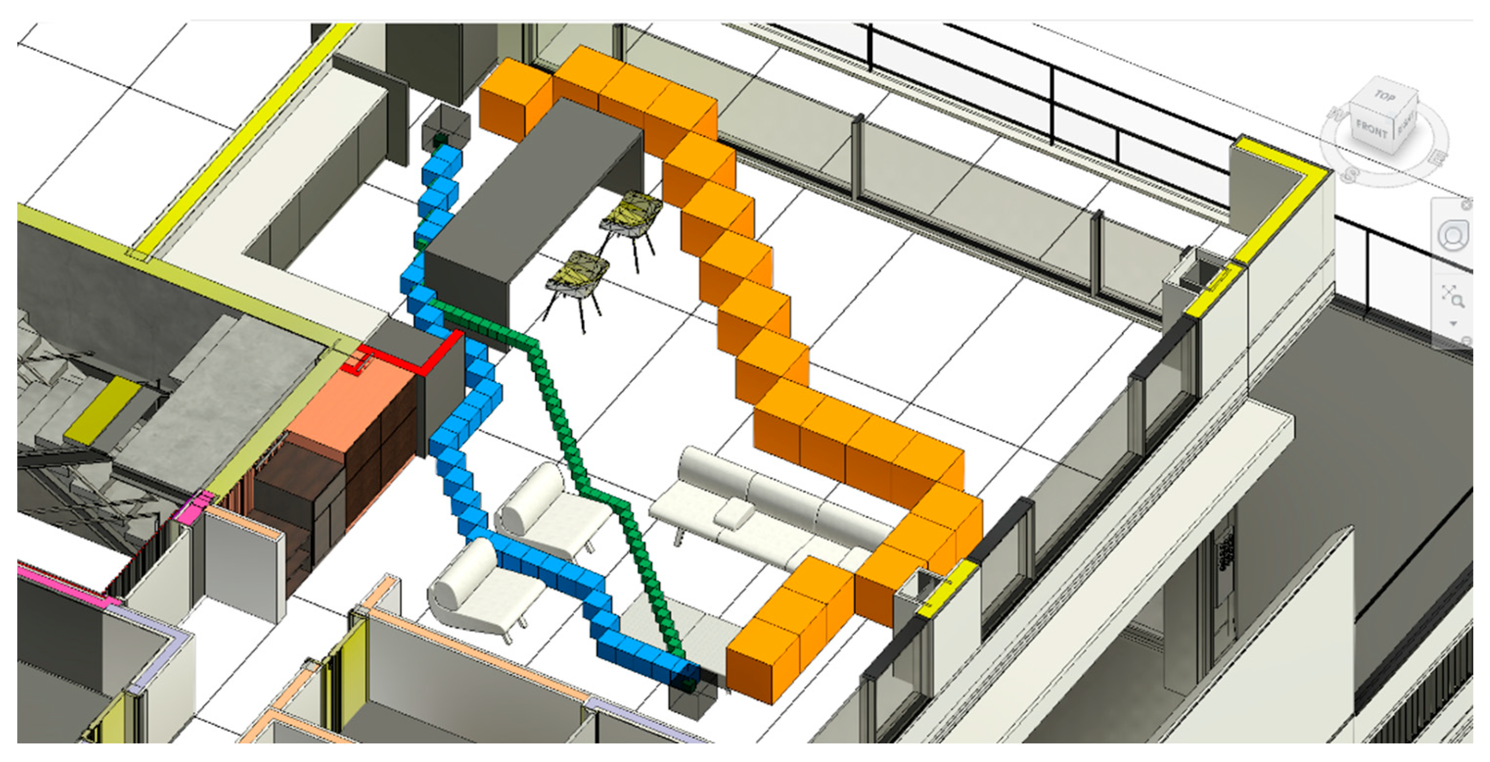
As shown in Figure 13a, voxels are generated using purple cubes for all the walls. A general safety distance of 20 cm is shown with the orange cube. Moreover, for curtain walls a 60-centimeter additional safety distance is executed using yellow cubes. The proposed path planning for both situations without special safety distance (blue cubes) and considering special safety distance (Green cubes) is shown in Figure 13b. Due to considering additional distance for curtain walls, the green path keeps a distance from the curtain wall better than the blue one, at the cost of a longer path length, while the blue path finds the shortest path from start position to the goal position (Table 6).

4.2.5. Validity Analysis of the Optimized Path for Multiple Targets Considering All the Effective Parameters

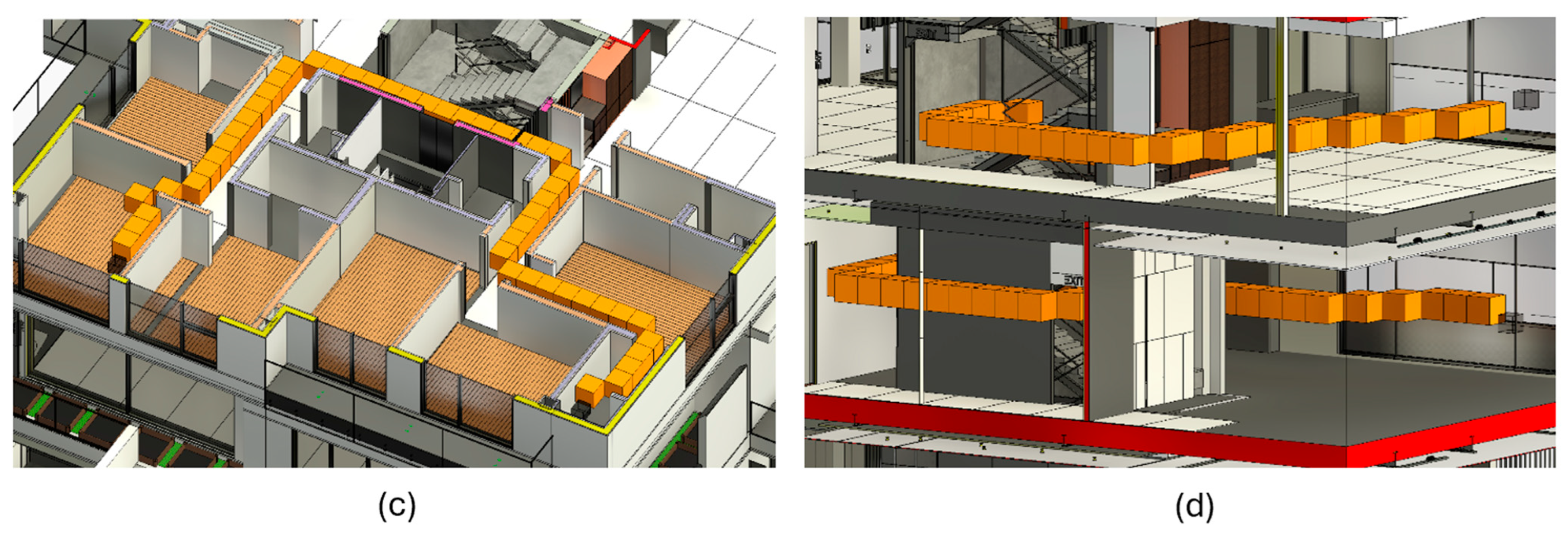
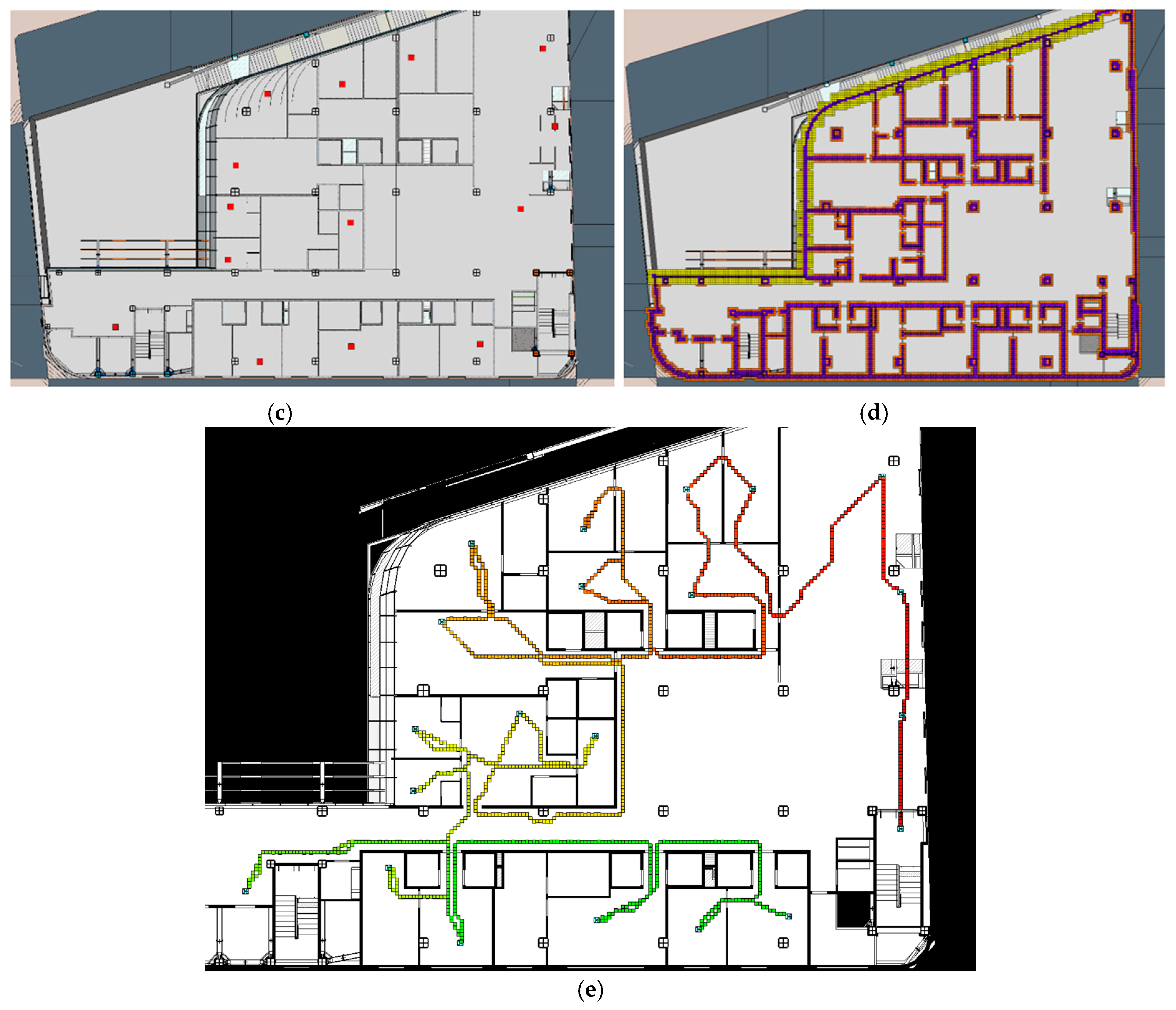
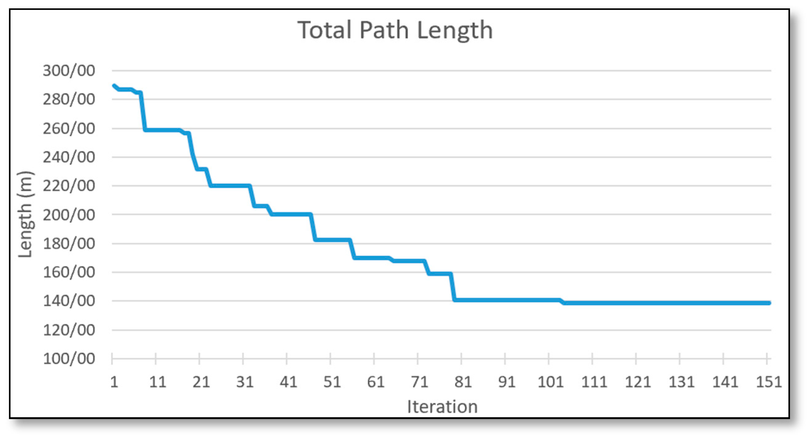
The primary purpose of this research is to find the optimal path for multiple targets in the dynamic environment of executing a construction project. To reach this goal, this research tries to consider the most effective parameters for path planning inside the project, like construction timestamps and under-construction elements (Figure 14b), workspaces, no-fly zones, and general and special safety distances of elements (Figure 14d). This research combines ACO and A* to find the optimum path between multiple target places. Results indicate the proposed framework finds the optimum path among several target visit places, as shown in Table 7 and Figure 14e. The performance of the ACO has been shown in Figure 15.

5. Discussion

This study provides several theoretical contributions to the body of knowledge in computational design and construction informatics. First, this work frames voxelization as more than a data processing step, positioning it as a conceptual model representation strategy that links geometric complexity with analysis-ready discretization. This advances theoretical understanding of how building information models can be abstracted for algorithmic reasoning. Second, the results demonstrate that efficiency in digital workflows should not be interpreted solely in terms of computational speed, but also through the elimination of redundant operations, such as repetitive voxelization. This contributes to theory by reframing efficiency as a property of process design rather than isolated task execution.
Semantic enrichment of the voxel model using BIM model data can improve the navigation of the drones. Previous BIM-based models had limitations for indoor navigation in the 3D environment and in different timestamps of the construction projects. This weakness impedes their application in activities like progress monitoring and quality inspection. Therefore, in this research, based on the existing research, a framework is proposed for applying the voxelization method to BIM models while keeping the relationship between voxels and BIM model entities. This helps to transfer BIM models’ data to the voxel model and apply it to voxels, considering the real-time situation of the project immediately, which was neglected in previous research, where a new voxel model had to be built each time. After applying the proposed framework to two real projects’ BIM models, the following results were obtained:
  • Some target positions may be unreachable due to intersection with model entities or being too close to the entities. Implementing A* on these positions leads to an endless loop, as no point can satisfy the A* ending condition. The proposed framework executes an initial filter to check the condition of the target positions by placing the cube’s center, which is two times bigger than the voxel size, in those positions and checking the intersection with model elements. This proves that there is at least a one-voxel-size distance between each target point and model elements, so the A* algorithm never falls into an endless loop.
  • Traditional path planning approaches mainly focus on the maintenance phase and neglect construction timestamps. This research proposed a framework for transferring the element’s construction time data from the BIM model to the voxel model. This makes the voxel model valuable for path planning in the indoor environment of construction projects. As the proposed framework works based on the predefined 4D model, the elements that were not considered in the 4D model like temporary storage or scaffolding may impede real execution of UAV flying. However, such elements could be considered in two manners. First, they could be modeled as a “temporary element” in the BIM model, with a start and end date like other elements, so that corresponding voxels will be added to the voxel model and considered in voxel map creation according to 4D model consideration in the path planning process of the proposed framework. Secondly another safety distance like “Scaffolding Distance” could be defined for each element in the projects as an attribute, and extra voxels required for them could be added, as has been performed with “special safety distance” in the proposed framework.
  • Safety distance is one of the most critical factors in path planning in indoor environments. While most of the research has focused on avoiding collision between the drone and the elements, there is a need for additional safety distance to reduce the risk of collision with construction elements. Moreover, fragile elements like curtain walls need more safety distance than others. The proposed framework considers both safety distances through the semantic enrichment of the voxel model. Two items, general safety distance and special safety distance, have been defined for this purpose. Several voxels have been placed around each model element, considering the general safety distance and the voxel size. Moreover, for each element in the BIM model with a special safety distance as an attribute, additional layers of voxels related to the specific element in the voxel model have been placed to occupy more space around the element and keep more distance in path planning.
  • As workspaces and no-fly zones like manager offices are not physical elements in the BIM model, there would not be any intersection with the placed voxels. So, an additional filter has been implemented for enriching the voxel model by transferring the coordinates of the defined workspaces in the BIM model to the voxel model coordinates and placing additional voxels in that space. This helps consider workspaces and avoid conflict between planned paths and workspaces.
  • Reaching multiple target goals requires an optimized path between each target, which is generally optimized among all the target goals. For this purpose, this research proposed an integration of ACO and A* for finding the shortest path to reach all the target positions. This results in the best-planned route in the project’s 3D environment.

6. Conclusions

This research is mainly focused on finding optimized flying paths for drones among multiple targets in the dynamic environment of construction projects, considering all the effective metrics. For this purpose, the first voxel model of the project is created using the BIM model. Then, an enriched voxel map is generated considering the voxel model and containing BIM model data. The required data, based on the flying time and the construction site situation, is extracted from the BIM model and implemented on the enriched voxel map as additional filters. At the end, a combination of ACO and A* is executed to find the optimized path in the voxel map.
This research encountered some limitations. First, current results reflect simulated scenarios, not yet real-time performance under real-world UAV operational conditions, which may reveal practical implementation issues. Although this research tried to omit the requirement for voxel model creation for each path planning purpose, another limitation of this study is that its focus was not on evaluating voxelization time; consequently, performance parameters such as computational efficiency and memory usage were not considered. As this aspect has also been overlooked in the prior literature, future research could address this gap by systematically assessing voxelization approaches (e.g., OBJ-based methods) in terms of processing time, memory consumption, and their broader advantages and disadvantages, while ensuring the fidelity of BIM model data is preserved.
The framework is validated on two building-type projects (residential and office), but its applicability to linear infrastructure like tunnels, bridges, or railways—characterized by elongated geometries and different spatial constraints—remains unexplored. Additionally, dynamic elements and temporary structures (e.g., scaffolding, cranes, or storage materials) can greatly affect UAV navigation. Future work could consider these scenarios and determine how they could be implemented on the enriched voxel map both in simulation and real-world projects.
Although this research tried to consider site conditions by considering elements’ construction time and workspaces for filtering path planning methods, air situations like wind or dust in the air were not considered. To address these factors, integrating real-time meteorological data from IoT sensors into the voxel map or using wind-resistant UAV dynamics models could be investigated in future research.
Moreover, future research could explore integrating voxel maps with space graphs in areas with existing structures to improve path finding efficiency. This study only treats workspaces as no-fly zones, but construction sites also have many moving machines. Subsequent studies could incorporate these machines and their movement paths into the analysis.

Author Contributions

Conceptualization, A.G.; methodology, A.G., M.K. and M.R.; validation, A.G. and M.R.; investigation, A.G., S.B. and M.S.; writing—original draft preparation, A.G., M.S. and S.B.; writing—review and editing, A.G., M.K., M.S., M.R. and S.B. All authors have read and agreed to the published version of the manuscript.

Funding

This research received no external funding.

Data Availability Statement

The original contributions presented in the study are included in the article, further inquiries can be directed to the corresponding author.

Conflicts of Interest

The authors declare no conflicts of interest.

References

  1. Molina, A.A.; Huang, Y.; Jiang, Y. A review of unmanned aerial vehicle applications in construction management: 2016–2021. Standards 2023, 3, 95–109. [Google Scholar] [CrossRef]
  2. Albeaino, G.; Gheisari, M.; Franz, B.W. A systematic review of unmanned aerial vehicle application areas and technologies in the AEC domain. J. Inf. Technol. Constr. 2019, 24, 381–405. [Google Scholar]
  3. Tavasoli, S.; Pan, X.; Yang, T. Real-time autonomous indoor navigation and vision-based damage assessment of reinforced concrete structures using low-cost nano aerial vehicles. J. Build. Eng. 2023, 68, 106193. [Google Scholar] [CrossRef]
  4. Rejeb, A.; Abdollahi, A.; Rejeb, K.; Treiblmaier, H. Drones in agriculture: A review and bibliometric analysis. Comput. Electron. Agric. 2022, 198, 107017. [Google Scholar] [CrossRef]
  5. Yucesoy, E.; Balcik, B.; Coban, E. The role of drones in disaster response: A literature review of operations research applications. Int. Trans. Oper. Res. 2025, 32, 545–589. [Google Scholar] [CrossRef]
  6. Panigati, T.; Zini, M.; Striccoli, D.; Giordano, P.F.; Tonelli, D.; Limongelli, M.P.; Zonta, D. Drone-based bridge inspections: Current practices and future directions. Autom. Constr. 2025, 173, 106101. [Google Scholar] [CrossRef]
  7. Kayhani, N.; Zhao, W.; McCabe, B.; Schoellig, A.P. Tag-based visual-inertial localization of unmanned aerial vehicles in indoor construction environments using an on-manifold extended Kalman filter. Autom. Constr. 2022, 135, 104112. [Google Scholar] [CrossRef]
  8. de Santos, L.M.G.; Nores, E.F.; Sánchez, J.M.; Jorge, H.G. Indoor path-planning algorithm for UAV-based contact inspection. Sensors 2021, 21, 642. [Google Scholar] [CrossRef]
  9. Zhong, W.; Rasouli, S.; Singh, A.K.; Mohandes, S.R.; Antwi-Afari, M.F.; Cheung, C.; Manu, P.; Agrawal, U. The adoption of UAVs for enhancing safety in construction industry: A systematic literature review. Intell. Infrastruct. Constr. 2025, 1, 3. [Google Scholar] [CrossRef]
  10. Soleymani, M.; Bonyani, M.; Attarzadeh, M. Autonomous resource management in construction companies using deep reinforcement learning based on IoT. arXiv 2022, arXiv:2208.08087. [Google Scholar] [CrossRef]
  11. Shang, Z.; Shen, Z. Real-time 3D reconstruction on construction site using visual SLAM and UAV. In Proceedings of the Construction Research Congress, New Orleans, LA, USA, 2–4 April 2018; pp. 305–315. [Google Scholar]
  12. De Croon, G.; De Wagter, C. Challenges of autonomous flight in indoor environments. In Proceedings of the 2018 IEEE/RSJ International Conference on Intelligent Robots and Systems (IROS), Madrid, Spain, 1–5 October 2018; IEEE: New York, NY, USA, 2018; pp. 1003–1009. [Google Scholar]
  13. Becker, K.; Oehler, M.; Von Stryk, O. 3d coverage path planning for efficient construction progress monitoring. In Proceedings of the 2022 IEEE International Symposium on Safety, Security, and Rescue Robotics (SSRR), Seville, Spain, 8–10 November 2022; IEEE: New York, NY, USA, 2022; pp. 174–179. [Google Scholar]
  14. Nguyen, T.T.; Nguyen, P.; Nguyen, C.; Tran, M. Examination of sampling-based path planning for indoor UAV using voxel grid-based Visual SLAM. In Proceedings of the 8th International Conference on Robotics and Artificial Intelligence, Singapore, 18–20 November 2022; pp. 26–31. [Google Scholar]
  15. Xu, Z.; Chen, B.; Zhan, X.; Xiu, Y.; Suzuki, C.; Shimada, K. A vision-based autonomous UAV inspection framework for unknown tunnel construction sites with dynamic obstacles. IEEE Robot. Autom. Lett. 2023, 8, 4983–4990. [Google Scholar] [CrossRef]
  16. Xu, L.; Xi, M.; Gao, R.; Ye, Z.; He, Z. Dynamic path planning of UAV with least inflection point based on adaptive neighborhood A* algorithm and multi-strategy fusion. Sci. Rep. 2025, 15, 8563. [Google Scholar] [CrossRef]
  17. Sheikhkhoshkar, M.; El-Haouzi, H.B.; Aubry, A.; Hamzeh, F.; Rahimian, F. A data-driven and knowledge-based decision support system for optimized construction planning and control. Autom. Constr. 2025, 173, 106066. [Google Scholar] [CrossRef]
  18. Shu, J.; Xia, Z.; Gao, Y. BIM-Based Trajectory Planning for Unmanned Aerial Vehicle-Enabled Box Girder Bridge Inspection. Remote Sens. 2025, 17, 682. [Google Scholar] [CrossRef]
  19. Amani, M.; Akhavian, R. Safe and trustworthy robot pathfinding with BIM, MHA*, and NLP. Constr. Robot. 2025, 9, 18. [Google Scholar] [CrossRef]
  20. Amani, M.; Akhavian, R. Bayesian BIM-Guided Construction Robot Navigation with NLP Safety Prompts in Dynamic Environments. arXiv 2025, arXiv:2501.17437. [Google Scholar] [CrossRef]
  21. Golpour, A.; Khanzadi, M.; Rahbar, M. Optimal UAV camera position for automated computer vision-based inspection of bolt looseness in steel structures based on 4D BIM. J. Civ. Struct. Health Monit. 2024, 15, 1557–1579. [Google Scholar] [CrossRef]
  22. Ibrahim, A.; Golparvar-Fard, M. 4D BIM based optimal flight planning for construction monitoring applications using camera-equipped UAVs. In Proceedings of the ASCE International Conference on Computing in Civil Engineering 2019, Atlanta, GA, USA, 17–19 June 2019; American Society of Civil Engineers: Reston, VA, USA, 2019; pp. 217–224. [Google Scholar]
  23. Martinez, J.G.; Albeaino, G.; Gheisari, M.; Issa, R.R.; Alarcón, L.F. iSafeUAS: An unmanned aerial system for construction safety inspection. Autom. Constr. 2021, 125, 103595. [Google Scholar] [CrossRef]
  24. Nwaogu, J.M.; Yang, Y.; Chan, A.P.; Chi, H.L. Application of drones in the architecture, engineering, and construction (AEC) industry. Autom. Constr. 2023, 150, 104827. [Google Scholar] [CrossRef]
  25. de Melo, R.R.S.; Costa, D.B. Integrating resilience engineering and UAS technology into construction safety planning and control. Eng. Constr. Archit. Manag. 2019, 26, 2705–2722. [Google Scholar] [CrossRef]
  26. Debnath, D.; Vanegas, F.; Sandino, J.; Hawary, A.F.; Gonzalez, F. A review of UAV path-planning algorithms and obstacle avoidance methods for remote sensing applications. Remote Sens. 2024, 16, 4019. [Google Scholar] [CrossRef]
  27. Zhu, Z.; Jeelani, I.; Gheisari, M. Physical risk assessment of drone integration in construction using 4D simulation. Autom. Constr. 2023, 156, 105099. [Google Scholar] [CrossRef]
  28. Mourtzis, D.; Angelopoulos, J.; Panopoulos, N. Unmanned Aerial Vehicle (UAV) path planning and control assisted by Augmented Reality (AR): The case of indoor drones. Int. J. Prod. Res. 2024, 62, 3361–3382. [Google Scholar] [CrossRef]
  29. Tan, Y.; Li, S.; Liu, H.; Chen, P.; Zhou, Z. Automatic inspection data collection of building surface based on BIM and UAV. Autom. Constr. 2021, 131, 103881. [Google Scholar] [CrossRef]
  30. Vasquez-Gomez, J.I.; Sucar, L.E.; Murrieta-Cid, R.; Lopez-Damian, E. Volumetric next-best-view planning for 3D object reconstruction with positioning error. Int. J. Adv. Robot. Syst. 2014, 11, 159. [Google Scholar] [CrossRef]
  31. Quin, P.; Paul, G.; Alempijevic, A.; Liu, D.; Dissanayake, G. Efficient neighbourhood-based information gain approach for exploration of complex 3d environments. In Proceedings of the 2013 IEEE International Conference on Robotics and Automation, Karlsruhe, Germany, 6–10 May 2013; IEEE: New York, NY, USA, 2013; pp. 1343–1348. [Google Scholar]
  32. Gao, F.; Wang, L.; Zhou, B.; Zhou, X.; Pan, J.; Shen, S. Teach-repeat-replan: A complete and robust system for aggressive flight in complex environments. IEEE Trans. Robot. 2020, 36, 1526–1545. [Google Scholar] [CrossRef]
  33. Tursinovich, Y.U. Geometric modeling of threedimensional space and body. Eurasian J. Phys. Chem. Math. 2022, 5, 85–88. [Google Scholar]
  34. Zhang, C.; Liu, H.; Tang, Y. Quantitative evaluation of Voronoi graph search algorithm in UAV path planning. In Proceedings of the 2018 IEEE 9th International Conference on Software Engineering and Service Science (ICSESS), Beijing, China, 23–25 November 2018; IEEE: New York, NY, USA, 2018; pp. 563–567. [Google Scholar]
  35. Zhang, C.; Zou, Y.; Dimyadi, J. Integrating UAV and BIM for automated visual building inspection: A systematic review and conceptual framework. In IOP Conference Series: Earth and Environmental Science; IOP Publishing: Bristol, UK, 2022; Volume 1101, p. 062030. [Google Scholar]
  36. Kaluđer, H.; Brezak, M.; Petrović, I. A visibility graph based method for path planning in dynamic environments. In Proceedings of the 2011 Proceedings of the 34th International Convention MIPRO, Opatija, Croatia, 23–27 May 2011; IEEE: New York, NY, USA, 2011; pp. 717–721. [Google Scholar]
  37. Huang, H.P.; Chung, S.Y. Dynamic visibility graph for path planning. In Proceedings of the 2004 IEEE/RSJ International Conference on Intelligent Robots and Systems (IROS) (IEEE Cat. No. 04CH37566), Sendai, Japan, 28 September–2 October 2004; IEEE: New York, NY, USA, 2004; Volume 3, pp. 2813–2818. [Google Scholar]
  38. Marie, R.; Ben Said, H.; Stéphant, J.; Labbani-Igbida, O. Visual servoing on the generalized voronoi diagram using an omnidirectional camera. J. Intell. Robot. Syst. 2019, 94, 793–804. [Google Scholar] [CrossRef]
  39. Swingler, A.; Ferrari, S. A cell decomposition approach to cooperative path planning and collision avoidance via disjunctive programming. In Proceedings of the 49th IEEE Conference on Decision and Control (CDC), Atlanta, GA, USA, 15–17 December 2010; IEEE: New York, NY, USA, 2010; pp. 6329–6336. [Google Scholar]
  40. Meysami, A.; Cuillière, J.-C.; François, V.; Kelouwani, S. Investigating the impact of triangle and quadrangle mesh representations on AGV path planning for various indoor environments: With or without inflation. Robotics 2022, 11, 50. [Google Scholar] [CrossRef]
  41. Biundini, I.Z.; Pinto, M.F.; Melo, A.G.; Marcato, A.L.; Honório, L.M.; Aguiar, M.J. A framework for coverage path planning optimization based on point cloud for structural inspection. Sensors 2021, 21, 570. [Google Scholar] [CrossRef]
  42. Chen, J.; Liu, D.; Li, S.; Hu, D. Registering georeferenced photos to a building information model to extract structures of interest. Adv. Eng. Inform. 2019, 42, 100937. [Google Scholar] [CrossRef]
  43. Sun, Y.; Li, H.; Tong, X.; Lei, Y.; Wang, D.; Guo, C.; Tang, J.; Shang, Y. A multi-unmanned aerial vehicle fast path-planning method based on non-rigid hierarchical discrete grid voxel environment modeling. Int. J. Appl. Earth Obs. Geoinf. 2023, 116, 103139. [Google Scholar] [CrossRef]
  44. Wang, Q.; Zuo, W.; Guo, Z.; Li, Q.; Mei, T.; Qiao, S. BIM voxelization method supporting cell-based creation of a path-planning environment. J. Constr. Eng. Manag. 2020, 146, 04020080. [Google Scholar] [CrossRef]
  45. Meagher, D. Geometric modeling use octree encoding. Comput. Graph. Image Process. 1982, 19, 129–147. [Google Scholar] [CrossRef]
  46. Zhou, X.; Xie, Q.; Guo, M.; Zhao, J.; Wang, J. Accurate and efficient indoor pathfinding based on building information modeling data. IEEE Trans. Ind. Inform. 2020, 16, 7459–7468. [Google Scholar] [CrossRef]
  47. Xie, R.; Zlatanova, S.; Aleksandrov, M.; Lee, J.B. A voxel-based 3D indoor model to support 3D pedestrian evacuation simulations. J. Build. Eng. 2024, 98, 111183. [Google Scholar] [CrossRef]
  48. Jamali, A.; Rahman, A.A.; Boguslawski, P. 3D topological indoor building modeling integrated with open street map. Int. Arch. Photogramm. Remote Sens. Spat. Inf. Sci. 2016, 42, 111–117. [Google Scholar] [CrossRef]
  49. Liu, L. Indoor semantic modelling for routing: The two-level routing approach for indoor navigation. A+ BE| Archit. Built Environ. 2017, 1–252. [Google Scholar] [CrossRef]
  50. Isikdag, U.; Zlatanova, S.; Underwood, J. A BIM-Oriented Model for supporting indoor navigation requirements. Comput. Environ. Urban Syst. 2013, 41, 112–123. [Google Scholar] [CrossRef]
  51. BuildingSmart. Building Smart, Industry Foundation Classes (IFC). 2013. Available online: https://standards.buildingsmart.org/IFC/RELEASE/IFC4_1/FINAL/HTML/schema/ifcproductextension/lexical/ifcspace.htm (accessed on 8 August 2025).
  52. Fu, C.; Aouad, G.; Lee, A.; Mashall-Ponting, A.; Wu, S. IFC model viewer to support nD model application. Autom. Constr. 2006, 15, 178–185. [Google Scholar] [CrossRef]
  53. Ham, Y.; Han, K.K.; Lin, J.J.; Golparvar-Fard, M. Visual monitoring of civil infrastructure systems via camera-equipped Unmanned Aerial Vehicles (UAVs): A review of related works. Vis. Eng. 2016, 4, 1. [Google Scholar] [CrossRef]
  54. Tschickardt, T.; Kaufmann, F.; Glock, C. Lean and BIM based flight planning for automated data acquisition of bridge structures with LiDAR UAV during construction phase. In Proceedings of the 2022 European Conference on Computing in Construction, St-Niklaas, Belgium, 24–26 July 2022; Volume 3. [Google Scholar]
  55. Tan, Y.; Li, G.; Cai, R.; Ma, J.; Wang, M. Mapping and modelling defect data from UAV captured images to BIM for building external wall inspection. Autom. Constr. 2022, 139, 104284. [Google Scholar] [CrossRef]
  56. Choi, J.; Kim, H.; Kim, I. Open BIM-based quantity take-off system for schematic estimation of building frame in early design stage. J. Comput. Des. Eng. 2015, 2, 16–25. [Google Scholar] [CrossRef]
  57. Ma, Z.; Wei, Z.; Song, W.; Lou, Z. Application and extension of the IFC standard in construction cost estimating for tendering in China. Autom. Constr. 2011, 20, 196–204. [Google Scholar]
  58. Zhang, S.; Teizer, J.; Lee, J.-K.; Eastman, C.M.; Venugopal, M. Building information modeling (BIM) and safety: Automatic safety checking of construction models and schedules. Autom. Constr. 2013, 29, 183–195. [Google Scholar] [CrossRef]
  59. Choi, J.; Choi, J.; Kim, I. Development of BIM-based evacuation regulation checking system for high-rise and complex buildings. Autom. Constr. 2014, 46, 38–49. [Google Scholar] [CrossRef]
  60. Mirahadi, F.; McCabe, B.; Shahi, A. IFC-centric performance-based evaluation of building evacuations using fire dynamics simulation and agent-based modeling. Autom. Constr. 2019, 101, 1–16. [Google Scholar] [CrossRef]
  61. Yan, W.; Culp, C.; Graf, R. Integrating BIM and gaming for real-time interactive architectural visualization. Autom. Constr. 2011, 20, 446–458. [Google Scholar] [CrossRef]
  62. Lin, Y.H.; Liu, Y.S.; Gao, G.; Han, X.G.; Lai, C.Y.; Gu, M. The IFC-based path planning for 3D indoor spaces. Adv. Eng. Inform. 2013, 27, 189–205. [Google Scholar] [CrossRef]
  63. Taneja, S.; Akinci, B.; Garrett, J.H., Jr.; Soibelman, L. Algorithms for automated generation of navigation models from building information models to support indoor map-matching. Autom. Constr. 2016, 61, 24–41. [Google Scholar] [CrossRef]
  64. Koch, C.; Neges, M.; König, M.; Abramovici, M. Natural markers for augmented reality-based indoor navigation and facility maintenance. Autom. Constr. 2014, 48, 18–30. [Google Scholar] [CrossRef]
  65. Boguslawski, P.; Mahdjoubi, L.; Zverovich, V.; Fadli, F. Automated construction of variable density navigable networks in a 3D indoor environment for emergency response. Autom. Constr. 2016, 72, 115–128. [Google Scholar] [CrossRef]
  66. Lee, J.K.; Eastman, C.M.; Lee, J.; Kannala, M.; Jeong, Y.S. Computing walking distances within buildings using the universal circulation network. Environ. Plan. B Plan. Des. 2010, 37, 628–645. [Google Scholar] [CrossRef]
  67. Li, N.; Becerik-Gerber, B.; Krishnamachari, B.; Soibelman, L. A BIM centered indoor localization algorithm to support building fire emergency response operations. Autom. Constr. 2014, 42, 78–89. [Google Scholar] [CrossRef]
  68. Zhang, J.; Luo, H.; Xu, J. Towards fully BIM-enabled building automation and robotics: A perspective of lifecycle information flow. Comput. Ind. 2022, 135, 103570. [Google Scholar] [CrossRef]
  69. Chen, Y.; Zhang, J.; Min, B.C. Applications of BIM and UAV to construction safety. In Proceedings of the CSCE Annual Conference, Laval, QC, Canada, 12–15 June 2019; pp. 1–7. [Google Scholar]
  70. Freimuth, H.; König, M. Planning and executing construction inspections with unmanned aerial vehicles. Autom. Constr. 2018, 96, 540–553. [Google Scholar] [CrossRef]
  71. Song, C.; Chen, Z.; Wang, K.; Luo, H.; Cheng, J.C. BIM-supported scan and flight planning for fully autonomous LiDAR-carrying UAVs. Autom. Constr. 2022, 142, 104533. [Google Scholar] [CrossRef]
  72. ISO 12100:2010; Safety of Machinery—General Principles for Design—Risk Assessment and Risk Reduction. ISO: Geneva, Switzerland, 2010.
  73. International Code Council. International Building Code (IBC), 2021st ed.; International Code Council: Washington, DC, USA, 2021. [Google Scholar]
  74. Ramirez-Atencia, C.; Bello-Orgaz, G.; R-Moreno, M.D.; Camacho, D. Solving complex multi-UAV mission planning problems using multi-objective genetic algorithms. Soft Comput. 2017, 21, 4883–4900. [Google Scholar] [CrossRef]
  75. Bui, D.N.; Duong, T.N.; Phung, M.D. Ant colony optimization for cooperative inspection path planning using multiple unmanned aerial vehicles. In Proceedings of the 2024 IEEE/SICE International Symposium on System Integration (SII), Ha Long, Vietnam, 8–11 January 2024; IEEE: New York, NY, USA, 2024; pp. 675–680. [Google Scholar]
  76. Hamledari, H.; Sajedi, S.; McCabe, B.; Fischer, M. Automation of inspection mission planning using 4D BIMs and in support of unmanned aerial vehicle–based data collection. J. Constr. Eng. Manag. 2021, 147, 04020179. [Google Scholar] [CrossRef]
  77. Banerjee, S.; Mondal, A.C. An intelligence technique for route distance minimization to store and marketize the crop using computational optimization algorithms. Sci. Rep. 2025, 15, 28705. [Google Scholar] [CrossRef]
Figure 1. Path planning approaches.
Systems 13 00917 g001
Figure 2. Traditional voxel model-based path planning.
Systems 13 00917 g002
Figure 3. Proposed framework for enriched voxel map-based path planning.
Systems 13 00917 g003
Figure 4. Voxel model space boundary and enriched voxel map data.
Systems 13 00917 g004
Figure 5. Traditional 4D BIM-based voxel model process.
Systems 13 00917 g005
Figure 6. Voxel map modification based on 4D BIM (free space(zero) for elements with start date after flying date).
Systems 13 00917 g006
Figure 7. Voxel map modification based on workspaces. (adding unnavigable(one) to the corresponding element of the modified voxel map for workspaces).
Systems 13 00917 g007
Figure 8. Additional voxels based on general and special safety distances. (purple for geometries, orange for general safety distance and yellow for special distance).
Systems 13 00917 g008
Figure 9. Spatial relationship and distance between adjacent voxels.
Systems 13 00917 g009
Figure 10. Path finding with different start and goal positions. (a,b) illustrate the identi-fied paths within the same floor and across different floors in Case Study (2), respectively; (c,d) depict the optimized paths generated for varying start and goal positions in Case Study (1).
Systems 13 00917 g010aSystems 13 00917 g010b
Figure 11. Path finding for different construction timestamps. Four key stages were tested: during the structural work of columns (a), during the construction of the exterior walls (b), and midway through the construction of the interior walls (c,d).
Systems 13 00917 g011
Figure 12. Path finding with different voxel sizes. (orang: 0.5 m, blue: 0.2 m, green: 0.1 m).
Systems 13 00917 g012
Figure 13. Path finding considering general and special safety distances. (a). General (orange) and special (yellow) safety distance voxels, (b). with (green and without (blue) safety distance path finding.
Systems 13 00917 g013
Figure 14. Multi-target path finding. (a). 3D BIM model, (b). 4D BIM model, (c). Target points, (d). general and special safety voxels, (e). optimum path.
Systems 13 00917 g014aSystems 13 00917 g014b
Figure 15. ACO performance in multi-target path planning.
Systems 13 00917 g015
Table 2. Case Studies.
IDNameNumber of Floors3D Model
1Residential Apartment7Systems 13 00917 i001
2Commercial Office Building12Systems 13 00917 i002
Table 3. Results of path planning for different start and goal positions.
IDStartGoalLength (m)Runtime (s)
1(−18.6, 3.1, 16.4)(−27.1, −22.8, 16.5)31.122.76
2(−39, −16.5, 17)(−39, −16.5, 22)39.753.45
3(−3, −5, 5.5)(9, −4, 5.5)26.650.37
4(8, 10.5, 1.5)(8, 11, 5.5)48.137.14
Table 4. Results of path planning for different timestamps of the projects.
IDStartGoalVoxel Size (m)Length (m)Runtime (s)
1(−12.7, −11.6, 16.5)(−36.6, 5.8, 16.6)0.531.230.57
2(−12.7, −11.6, 16.5)(−36.6, 5.8, 16.6)0.533.991.01
3(−12.7, −11.6, 16.5)(−36.6, 5.8, 16.6)0.538.392.16
4(−12.7, −11.6, 16.5)(−36.6, 5.8, 16.6)0.542.533.75
Table 5. Results of path finding with different voxel sizes.
IDStartGoalVoxel Size (m)Length (m)Runtime (s)
1(8.5, 5, 4.8)(2.5, 10.5, 4.8)0.512.280.03
2(8.5, 5, 4.8)(2.5, 10.5, 4.8)0.29.730.36
3(8.5, 5, 4.8)(2.5, 10.5, 4.8)0.18.9210.04
Table 6. Results of path finding considering general and special safety distances.
IDStartGoalVoxel Size (m)ColorLength (m)Runtime (s)
1(−41.5, −18, 1.5)(−30.5, −11, 1.5)0.2blue15.851.65
2(−41.5, −18, 1.5)(−30.5, −11, 1.5)0.2green17.112.32
Table 7. Results of multi-target path finding.
IDNumber of TargetsNumber of Interval StepsVoxel Size (m)ColorTotal Length (m)Runtime (s)
12113890.2RGB289.34189.08
Disclaimer/Publisher’s Note: The statements, opinions and data contained in all publications are solely those of the individual author(s) and contributor(s) and not of MDPI and/or the editor(s). MDPI and/or the editor(s) disclaim responsibility for any injury to people or property resulting from any ideas, methods, instructions or products referred to in the content.