Article

Systemic Conception of the Data Acquisition of Digital Twin Solutions for Use Case-Oriented Development and Its Application to a Gearbox

1
Product and Systems Engineering Group, Technische Universität Ilmenau, Max-Planck-Ring 12, 98693 Ilmenau, Germany
2
Department for Product Development and Machine Elements, Technical University Darmstadt, Otto-Berndt-Straße 2, 64287 Darmstadt, Germany
*
Author to whom correspondence should be addressed.
Systems 2023, 11(5), 227; https://doi.org/10.3390/systems11050227
Submission received: 27 March 2023 / Revised: 24 April 2023 / Accepted: 26 April 2023 / Published: 4 May 2023
(This article belongs to the Section Systems Engineering)

Abstract

:
Digital Twins are being used more and more frequently and provide information from the Real Twin for different applications. Measurements on the Real Twin are required to obtain information, which in many cases requires the installation of supplementary sensors. For their conception and design, it is particularly important that the measuring principles are selected purposefully and the appropriate sensors are integrated at the goal-oriented measuring positions without impairing the functions and other properties of the Real Twin by the integration of these sensors. In this article, a “Design for Digital Twin” approach is discussed for the systematic procedure and demonstrated using a multi-staged gearbox as a concrete example. The approach focuses on the mechanical and hardware side of the Real Twin. For the systematic conception and design of the Digital Twin solution, an understanding of the stakeholder demands and the expected use cases is necessary. Based on the stakeholder demands and use cases, the relevant product properties can be determined. Using the relevant properties, an iterative process of conception, design, and analysis takes place. The conception is carried out by means of target-oriented cause–effect analyses, taking into account systemic interrelations of the Real Twin components and systematics for the selection of measurement principles. Systemic considerations, combined with an effect graph, allow for the analysis and evaluation of disturbing factors.

1. Introduction

Digital Twins support different use cases in several product life phases (e.g., predictive maintenance during usage, sustainability assessment of products during use, provision of services, support of remote control, feedback of insights from product usage for further development, support of verification and validation through a systematic comparison of model-based descriptions of the Real and Digital Twins during development, etc.) [1,2,3,4,5,6]. For this purpose, information is exchanged between the Real and Digital Twin and processed in the Digital Twin (e.g., in form of simulations of the expected behavior of the Real Twin), which ultimately leads to application-specific actions in the Real and Digital Twin. There are different types of Digital Twins for different use cases. Wilking distinguishes between Informational Digital Twin (IDT), Supporting Digital Twin (SDT), and Autonomous Digital Twin (ADT) [7].
The basic system of the Real Twin usually also exists without a Digital Twin, so that the essential purpose of the technical product can be realized [8]. The combination of a Digital Twin and an extension of the Real Twin for bi-directional communication between the Real and Digital Twin should be referred to as the Digital Twin Solution (see Figure 1). In Figure 1, the term Digital Master is used during development, as this is the starting point for the Digital Twin Solution during development.
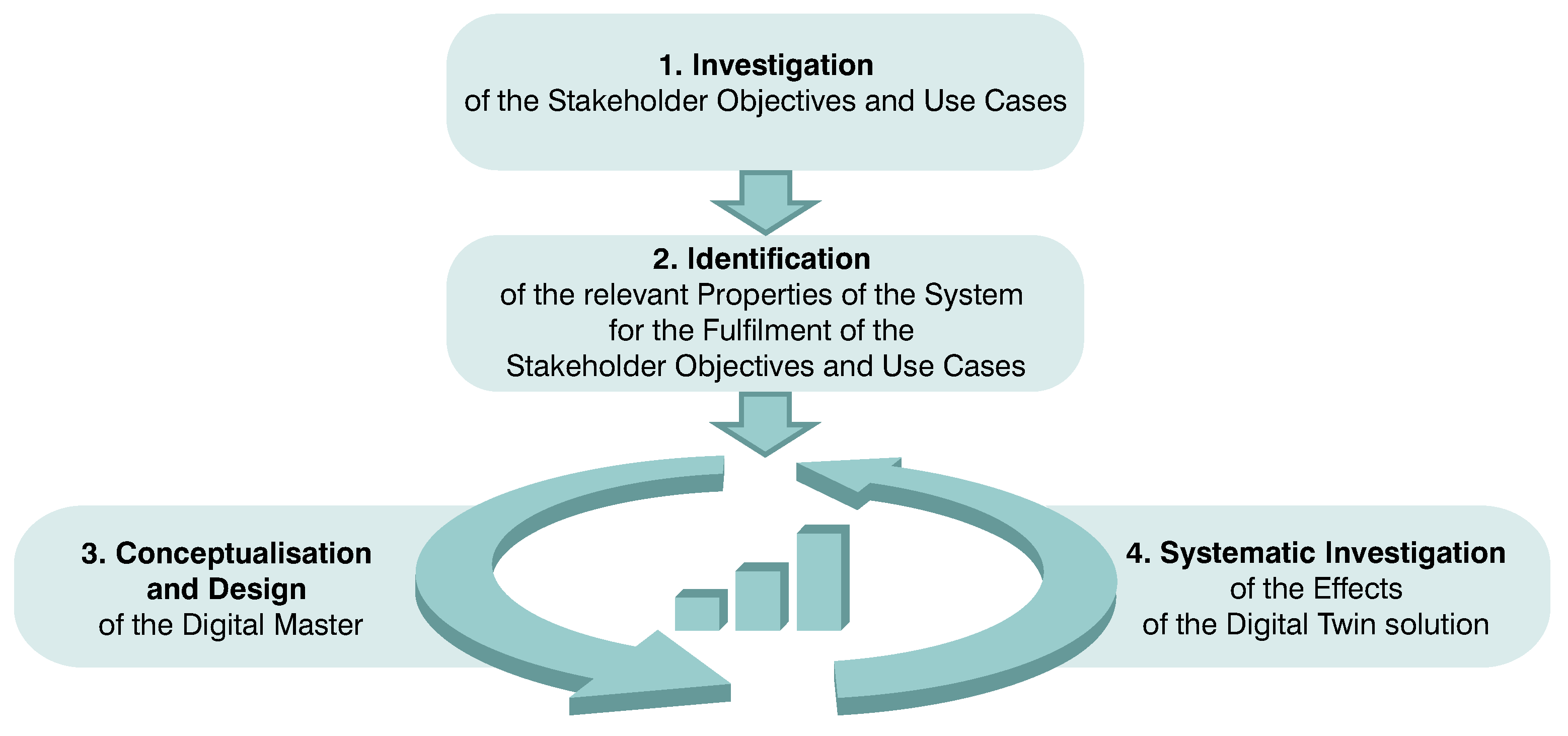
In order for the Digital Twin Solution (especially through the specific extension of the Real Twin) to meet the demands in the best possible way, while ensuring that the Digital Twin Solution does not compromise the basic functions of the Real Twin, these must be developed systematically. It is particularly important to design and detail the extension of the Real Twin to a Digital Twin Solution in a targeted manner. In order to support the systematic development as needed, there are approaches for the development of Digital Twins [9]. For the systematic and need-oriented development of Digital Twin Solutions, Koch and Husung [6] proposed an approach that consists of four steps and focuses on the aspects shown in Figure 2. Much work already exists on the other aspects of Digital Twin Solutions, some of which should be mentioned here [10,11,12,13].
The objective of this contribution is to detail the approach proposed by Koch and Husung [6] for a specific use case, apply it to a multi-stage gearbox, and validate the approach in a context-specific manner. The following research questions are in focus:
  • How can concepts for Digital Twin Solutions (with the relevant focus—see Figure 2) for a multi-stage gearbox for specific applications be systematically determined?
  • How can different concepts of the Digital Twin Solution for a multi-stage gearbox be systematically compared and evaluated?
To answer the research questions, this paper is structured as follows: Section 2 briefly explains the relevant state of the art. The specification and application of the approach as well as context-specific validation are discussed in Section 3. The approach is alternately specified, applied, and validated specifically to the specific product and use case. Section 4 summarizes the results. In this section, the conclusions are also discussed and a brief outlook is provided.

2. State of the Art

2.1. Conception of the Digital Twin Solution

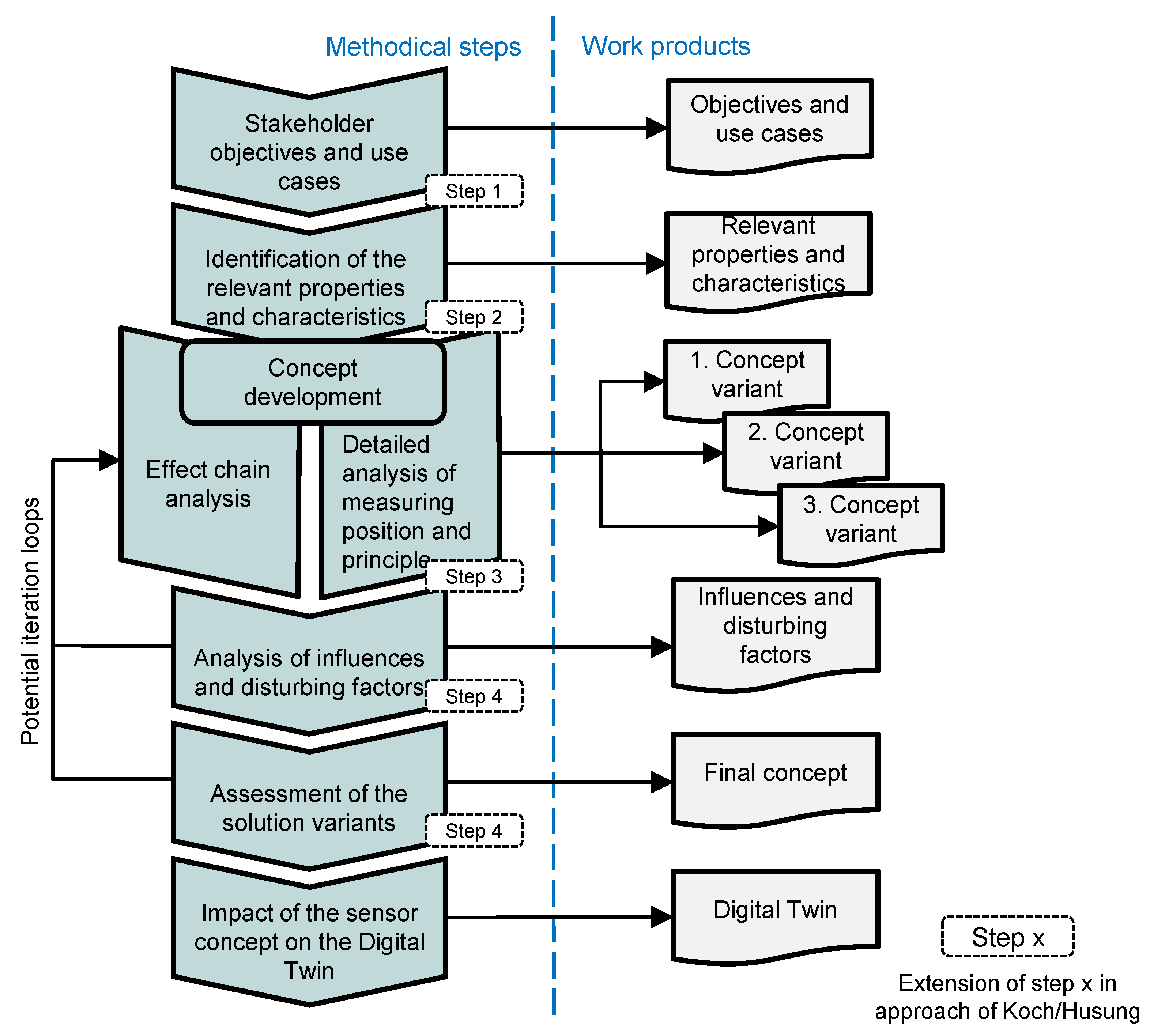
The development of Digital Twin Solutions encompasses many facets. Many scientific works deal with the identification of requirements for the Asset Administration Shell [11,14], the definition of the associated Digital Twin models, and the processing of the information within the Digital Twin [10], and show approaches as well as solutions for their realization. In this context, interoperability, model quality, model exchange, and extensibility as well as the processing of the information are discussed [10,12,15,16]. The Industry 4.0 platform has published a specification of the Asset Administration Shell for industrial applications [14,17]. In this context, Eickhoff presents a holistic concept for Digital Twin development [9]. One aspect that has been little discussed so far in the context of the Digital Twin is the necessary systematic extension of the Real Twin in order to realize the data acquisition for the use cases of the Digital Twin. Koch and Husung [6] presented an approach to address this issue. The structure of the approach is shown in Figure 3. This paper will build on this approach. Against this background, the approach will be briefly presented.
In the first step of the approach, the specific stakeholder demands and expected use cases must be identified and concretized in such a way that the relevant product properties, which must be identified from the Real Twin and processed in the Digital Twin, can be derived. Furthermore, by defining and concretizing the expected use cases, the use context of the Real Twin and thus therein occurring disturbance factors become apparent. These factors must be taken into account when developing Digital Twins to ensure the accuracy and robustness of the behavior. Depending on the development and implementation status of the technical product, different levels of maturity of the relevant properties can be determined. Based on the identified relevant properties, an iterative process of conception, design, and analysis is carried out (see Figure 3).
The approach requires concrete detailed approaches for the selection of the measuring principle and the sensors. Against this background, the state of the art of the specific measuring principle and sensor selection will be discussed in the next sections.

2.2. Sensing Machine Elements

Sensing machine elements (SMEs) are based on conventional, standardized machine elements and extend their primary mechanical functions with sensory functions [18,19]. The sensory extension of machine elements enables the measurement of a measurand in products without having to redesign the entire product, but by replacing an already included conventional machine element by an SME. SMEs arise alongside standard sensors that are integrated with products. The development of SMEs is the current subject of application-oriented development, but also of fundamental research. Vorwerk-Handing et al., describe the conceptual formulation of various types of SME and their differentiation from each other: sensor-carrying machine elements (ScMEs), sensor-integrating machine elements (SiMEs), and sensory utilizable machine elements (SuMEs) [18]. ScMEs have an additional sensor element and the measurand is not related to the mechanical function of the machine element. SiMEs also have an additional sensor element integrated but the measurement is related to its primary mechanical functions. SuMEs do not have an additional sensor element integrated but their properties are used to create the sensory function. Exemplary descriptions of such concepts are still comparatively rare. Another example of a SME is a sensor-integrated gear to detect wear by Peters et al. [20]. These have the possibility for data transmission to a Digital Twin. Bonaiti et al. [21] describe the influence of sensor integration on the Real Twin.
The concept of sensing machine elements was extended to design elements in general by Harder et al. [22]. Sensor-carrying design elements (ScDE) and sensor-integrating design elements (SiDE) are classical sensor integrations into design elements, which are not standardized. However, sensor utilizable design elements (SuDE) are a sensory extension that have been little considered so far.

2.3. Approaches for Sensor Selection

There are different methods for selecting suitable sensors for the measurement of specific flow or state variables of technical products. For the discussions in this paper, the ”Sensory utilizable Design Elements” (SuDE) methodology by Kraus et al. [23] is applied, the main steps of which will be explained in more detail below. The individual steps of the methodology are supported by an effect graph, which is a digitized effect catalog using a graph-based effects database [24].
In the first step of the methodology, principal solutions for the targeted introduction of sensory functionalities are determined. Starting from the point of interest (the place where the relevant quantity is to be determined), neighboring components are considered and the measurand or the quantity to be measured is used as an input variable in the effect graph. Effects that allow direct conversion of the measurand into an electrical output signal are systematically searched for. Suitable effective contact surfaces (or lines or spaces) within the component must be identified for each effect found. Such effective contact surfaces must be identified taking into account the necessary system-dependent (e.g., kinematic) properties of the effect under consideration. It can then be checked whether the component or the effective contact surface itself is suitable as an effect carrier. For this purpose, the adjustability of the component-specific properties (e.g., material properties) is checked in order to meet the necessary requirements for realizing the considered physical effect. Both the identification of effective contact surfaces and the adjustment of the physical properties of the design element can be supported by additional information stored in the corresponding node of the effect graph. Furthermore, effect chains, which represent a known sensor solution, can also be considered to measure the quantities to be measured in order to introduce sensory functionality in design elements. The changes made to the product must be contemplated critically concerning their feasibility. Design element tolerances as well as installation space restrictions must be taken into account. The found physical effect chain must be reversible to fulfill its resulting measurement function. The result of this step is a list of feasible solutions for SuDEs.
In the next step, the robustness of the feasible solutions against the influence of disturbance factors is assessed. This step is necessary since measurements in machines are typically performed under extreme environmental conditions present. Solutions are sought for that have the lowest possible sensitivity to be influenced by disturbance factors. The systematic identification of potential disturbance factors is carried out using an effect graph [24]. For each feasible solution, the underlying physical effect (intended effect) is analyzed concerning potential indirect superpositions. Such indirect superpositions are physical effects (unintended effects) that are caused by occurring disturbance factors.
In the final step, the found solutions are evaluated using generalized evaluation criteria to obtain a ranked list of feasible SuDEs at the end of the methodology. Based on this, a design element to be implemented can be selected [23].

3. Detailing of the Approach Using the Multi-Stage Gearbox

In this section, the approach of Koch and Husung [6] is detailed and described in the following in order to answer the above-formulated research questions (see Figure 4) and applied to the multi-stage gearbox (the text with the concrete application to the multi-stage gearbox is written in italics).
In the following explanations, terms from system modeling and measurement are used. The metrological terms are based on the International Vocabulary of Metrology [25]. The modeling terms are based primarily on system theory and modeling recommendations [26].

3.1. Stakeholder Objectives and Use Cases

The systematic development of the Digital Twin Solution requires an understanding of the planned or expected Digital Twin use cases of the different stakeholders in the life phases. Systems engineering approaches [27] are used to determine the stakeholders and use cases, including the systematic analysis of the different life phases and the determination of the demands of the relevant stakeholders in the life phases. The demands of internal stakeholders can concern the improvement of their tasks in development or production in the context of the product. In the context of Digital Twins, there are also demands of external stakeholders in connection with new business models (e.g., data-based services or assessment of the sustainability of products or processes based on carbon footprint).
Application to the multi-stage gearbox: Different use cases are important for the gearbox in which a Digital Twin Solution provides added value. A few selected use cases will be discussed below. The gearbox as an industrial product must guarantee the desired function over a long period of time and possible failures should be detected at an early stage by monitoring the wear (see Figure 5). The end users and those responsible for maintaining the gearbox are interested in this use case. Another application in this context is the early detection of assembly errors, which can also lead to increased wear. The further explanations focus on the first use case.

3.2. Identification of the Relevant Properties and Characteristics

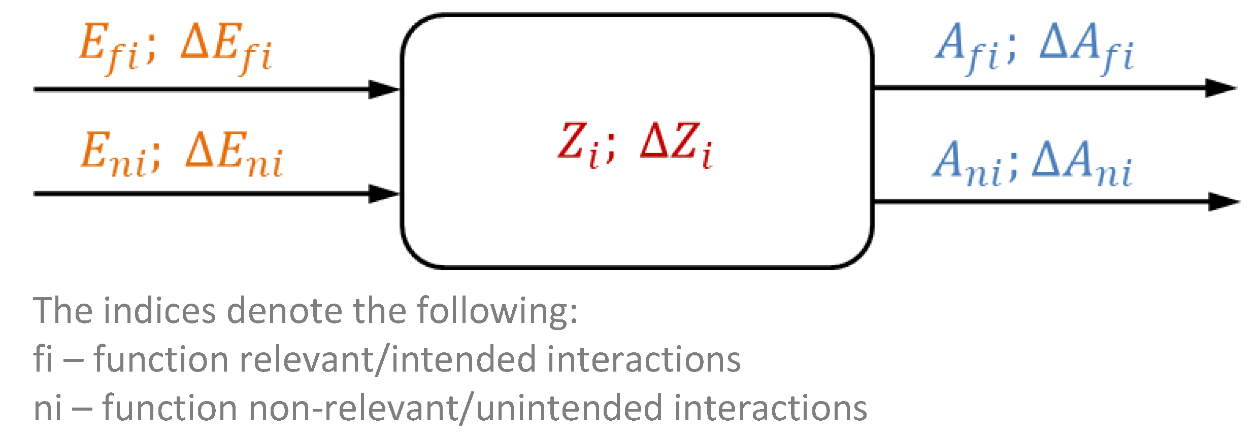
The objective of the second step of the approach is to determine which product properties and characteristics (definition according to Characteristics-Properties Modeling and Property-Driven Development (CPM/PDD) [28]) are relevant for the realization of the use cases. Direct and simulation-specific product properties are required for the use cases. Direct means that these represent an output value of the use case without further transformation (e.g., consumption information or emission values). Since these properties often cannot be identified directly, models and associated simulations are necessary. The input variables for the simulations are in turn simulation-specific properties that are required in addition to the product characteristics in order to determine the output variables of the use cases (see Figure 6). The simulation-specific properties are relevant variables of the simulation model. This means that the logical and physical relationships or even mathematical models in the Digital Twin must already be taken into account for the determination of the relevant properties. Dependencies between relevant properties, input variables, and internal product characteristics are provided by the analysis of the product on the basis of systemic analysis (see Figure 7).
Application to the multi-stage gearbox: The function (transformation of the intended input variables into the intended output variables—see Figure 7) of the gearbox is defined by its active surfaces and their relative arrangement (product characteristics Z in Figure 7). An important active surface for each gear is the tooth flank, which in combination with the second tooth flank forms the functionally important active surface pair. The tooth flanks are heavily stressed by the rolling process and can wear out. According to Figure 7, this leads to a ΔZ. The wear (deviation of the product characteristics ΔZ) leads to changes in the intended output variables Δ A f i and can lead to other unintended output variables A n i , such as sound, etc. Against this background, the movement and shape of the tooth flanks (associated product characteristics) are particularly relevant for monitoring wear (relevant property) in gearboxes. In addition to the shape of the tooth flanks, other product characteristics and environmental influences (e.g., temperature, etc.) also play an important role in reality, which cannot be discussed here for reasons of space. Since wear as a property cannot be measured directly, substitute variables are to be simulated for this in the Digital Twin using models. To determine the sensible variables (simulation-specific properties and product characteristics), an analysis of the causal relationships in the Real Twin and a conception based on this, including possible measurement principles, is necessary. This analysis is part of the following steps.

3.3. Concept Development

After the relevant properties have been determined, the main step in developing the Digital Twin Solution is the conception of the necessary measurement of the properties and finally elaboration of the concept. In this contribution, the main objective is the conception (for the aspects shown in Figure 2). During the conception, the best-suited measuring principle in connection with the measuring position must be determined.
It should be noted that the properties relevant to the use case often cannot be measured directly because, e.g., no sensor can be placed at the relevant points in the product or the relevant measurand cannot be determined or can only be determined inadequately using the available measurement principles. As already described in Section 3.2, substitute variables to be measured must therefore be determined. These substitute variables can be located at other places in the Real Twin and can be other property types (e.g., instead of a force, the resulting deformation is measured). To identify and systematically compare possible alternatives for the determination of the substitute variables, the cause-effect relationships in the product (i.e., between the use case relevant properties and the substitute properties) must be understood. This requires a systemic analysis of the cause-effect relationships. This means that the effect chains must be considered across the individual components of the product. Effect chains are models of expected propagation paths of the functional variables through the products. The functional variables are primarily effort variables (such as velocities or electrical voltages) and flow variables (such as forces or electrical currents), for some investigations the signals are also considered. In reality, the functional variables of different sources of course interfere with each other. For many observations, it is useful to analyze the different propagations of the functional variables along the effect chains separately.
As with the product development of the basic product itself, different scenarios should be taken into account (good-case scenarios, in which there are ideal interactions without disturbance factors, and worst-case scenarios, in which there are possible disturbances in the interactions or external disturbance factors – for the example of the gearbox, superimposed vibrations caused by the drive).
The analysis of the cause-effect relationships can be carried out in several steps. For the understanding of the basic product, an analysis of the initial solution (pure Real Twin) is necessary. By the necessary modification of the basic system for the Digital Twin Solution, the cause-effect relationships of the basic product can be influenced (e.g., by incorporating components into the force flow). In addition, further cause-effect relationships are generated by the Digital Twin Solution (e.g., the effect chain for the evaluation of the measurand). Therefore, an analysis of the cause-effect relationships should also be carried out for the alternatives of the Digital Twin Solution (extended Real Twin).
The description and analysis of the interactions can be performed using different methods (e.g., qualitatively through simple function descriptions, e.g., quantitatively utilizing four-pole modeling theory, bond graphs, etc.). In this contribution, a method based on the four-pole theory is recommended since the bidirectional interactions of the effort and flow variables can be represented expediently in this way and different four-pole models for machine elements already exist [30]. Four-poles are a representation for describing the transmission behavior of components at discrete interfaces [31] (see also Figure 8). Four-poles can be coupled with each other at the interfaces in order to describe the behavior of more complex systems by networking the four-poles.
The description of the interactions between the four-poles is used to apply the SuDE methodology [23] for the systematic identification of SuDE. This allows concrete decisions to be made on measurement principles and sensor selection for specific design elements based on the interactions and physical properties found. For the analysis of the cause-effect relationships, this means concretely:
  • use of four-pole for the overall analysis of the Real Twin (ultimately down to the direct and simulation-specific product properties—see Section 3.2)
  • use of the SuDE methodology for the detailed analysis of the individual design elements concerning the suitability for the determination of the product properties and the selection of the measurement principle.
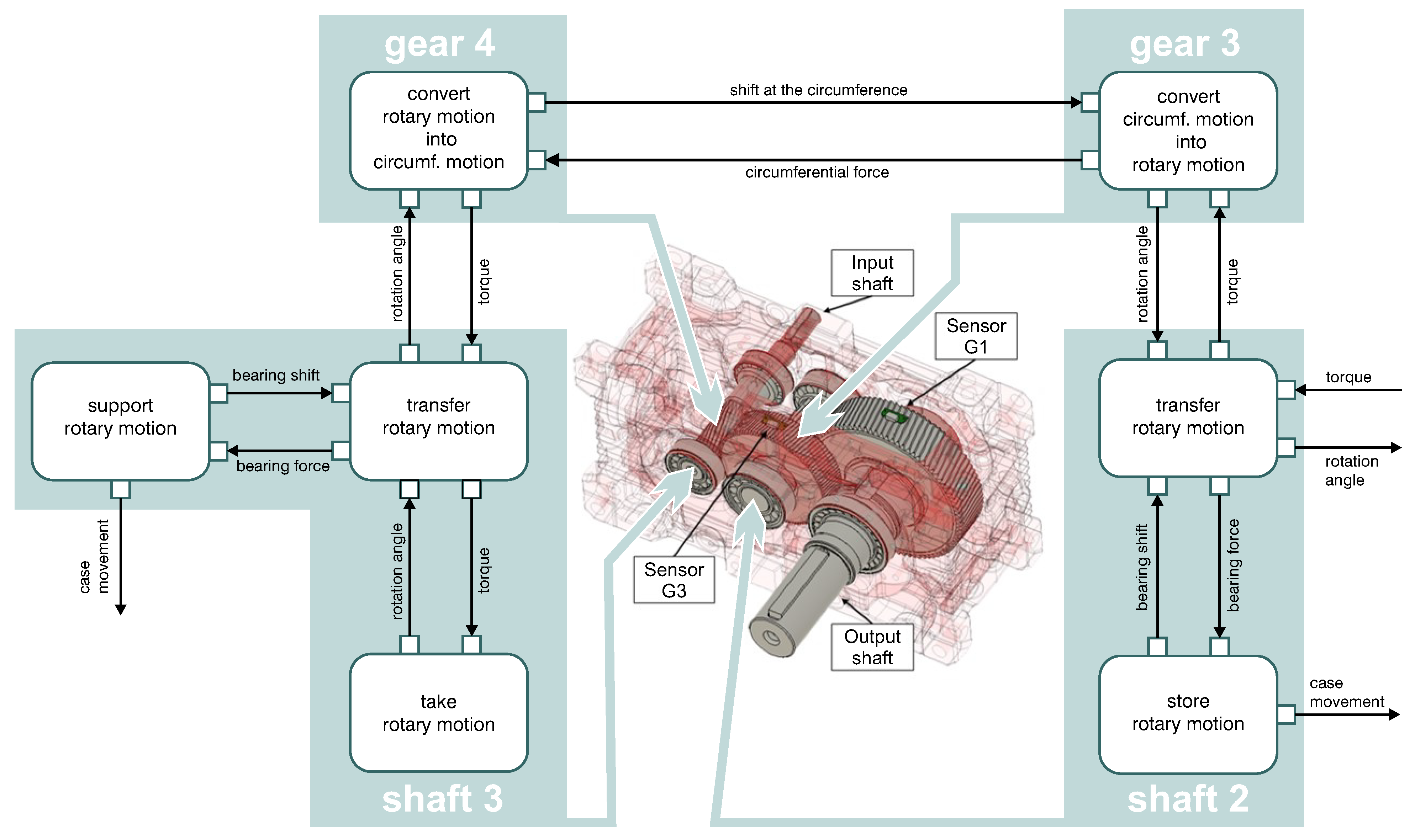
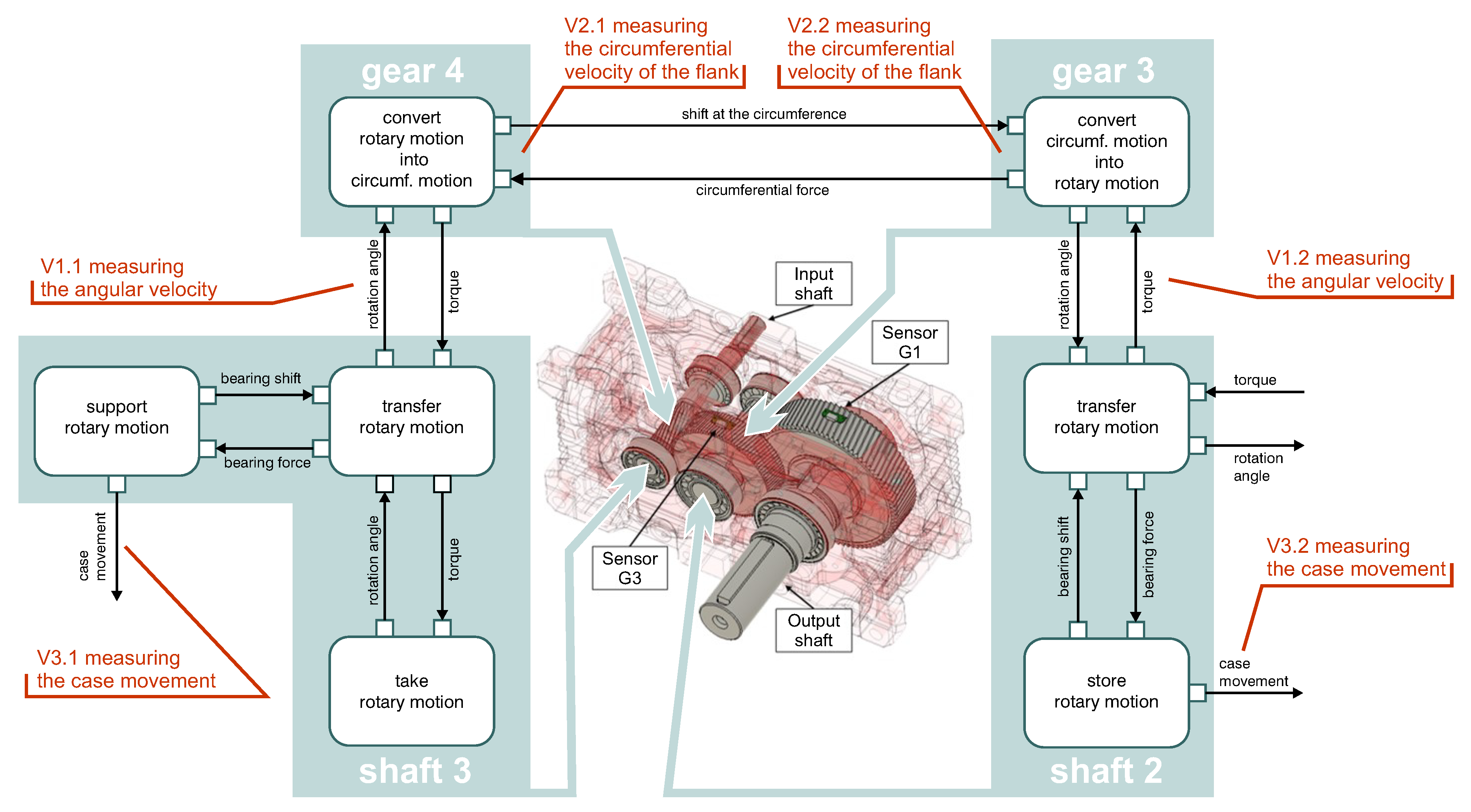
Application to the multi-stage gearbox: Figure 9 shows the four-pole model of the gearbox incl. the interactions between the gearbox components. As discussed above, the shape of the tooth flanks must be monitored for application. If there are deviations due to wear (ΔZ in Figure 7), constant changes in the angle of rotation at the input shaft will result in fluctuations in the displacement of the tooth flanks and ultimately fluctuations in the angle of rotation at the output shaft. In addition, these speed fluctuations are transmitted to the housing via the bearings. These relationships emerge from the model in Figure 9. The analysis of the effect chain thus provides several variants via which model parameters and for the Real Twins via which measurands the relevant properties can be determined. For the gearbox, three variants are shown in Figure 10. The variations in the shape of the tooth flanks lead to fluctuations in the kinematic variables, which can be measured at different positions. The variants are (see Figure 10):
  • V1: Measurement of the direct flank movement on the gear,
  • V2: Measurement of the rotary motion on the shaft,
  • V3: Measurement of the vibration at the gearbox housing,
  • V4: Measurement of the acoustic emission [32] and
  • V5: Measurement of the motor current fluctuation.
For comprehensive analyses, all known solution approaches should be considered if possible. Due to the space available in the paper, only the first three approaches (V1–V3) will be considered in the following. Using the SuDE methodology (see Section 2.2), detailed considerations of the possible measuring principles and sensory concepts can be carried out for the different position variants. For example, in V1, this could lead to the application of a magneto-resistive sensor system that detects the tooth flanks of the gears involved in the rolling contact. Another solution for V3 could be to detect the resulting vibrations, which are propagated through the product, by means of an accelerometer attached to the housing [33].
The transmission error can also be measured for variants V1 and V2 with additional reference measurements at two measurement positions. However, this is not discussed further in this contribution.

3.4. Analysis of Influences and Disturbing Factors

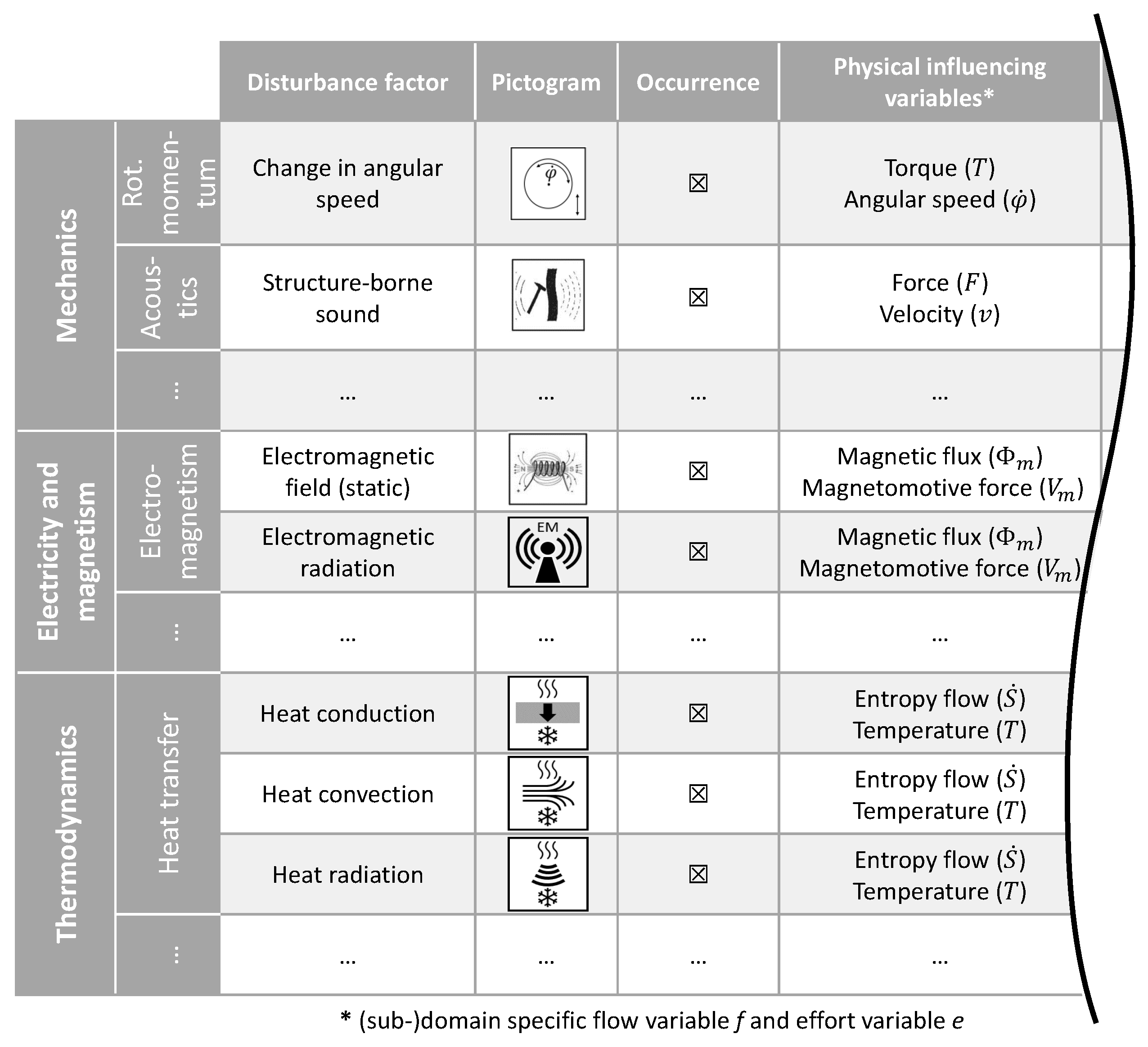
As shown in Figure 7, when functions are implemented in real products, in addition to the nominal intended input variables (in the case of the gearbox, these are, e.g., speed variations on the input shaft), there are also unintended input variables in the form of disturbance factors (e.g., thermal influences leading to expansions, etc.). These deviations and other unintended input variables ultimately lead to changes in the output variables. For the systematic identification of unintended input variables in the form of disturbance factors, e.g., the disturbance factor control list (see Figure 11) by Welzbacher et al. [34] can be used, which builds on the fundamentals of four-pole-based modeling. The characterization and quantification of the disturbance factors listed in the control list are based on the (sub-) domain-specific flow and effort variables, the product of which describes the generalized power transported into or out of the system. With the help of the characteristic flow and effort variables of the identified disturbance factors in connection with the four-pole approach for the cause-effect relationships as well as the effect graph by Kraus et al. [24], the impacts of identified disturbance factors on the conceived cause-effect relationships can then be systematically analyzed and described.
When a disturbance factor is found to have an impact on the considered cause-effect relationship, this disturbance factor must be included in the modeling of the effect chain in order to ensure the reliability of the analysis results. Alternatively, based on the robust-design strategies by Mathias et al. [35] or the approaches described by Brix [29] (see also Figure 12), measures can be developed and implemented to control the disturbance factor or its impact during function implementation in the Real Twin. The effectiveness of the respective robust design strategies and the approaches by Brix [29] have to be investigated system-specifically and for the respective applications.
Application to the multi-stage gearbox: Modeling the system by means of the cause-effect relationships (shown only with nominal values in Figure 10) also allows the deviations and other input variables, e.g., in form of disturbance factors, to be described and their impacts to be analyzed. It becomes apparent, among other things, that speed and torque deviations as well as settling also lead to a deviation in the movement of the tooth flanks. The resulting movement deviation must be distinguished from the wear-induced deviations and can be realized, e.g., by a separate measurement of the input variables and subsequent compensation of their impacts in signal processing.

3.5. Assessment of the Solution Variants

After determining the solution variants, the best-suited variant must be selected. Different criteria should be used for the evaluation (see also evaluations according to Pahl/Beitz [36] or VDI 2225 [37]). In the context of the Digital Twin Solution, it is important to assess how well the respective solution variants fulfill the Digital Twin use cases. Since not only Digital Twin use cases are relevant, but also the functionality of the basic product must be ensured, criteria for influencing the basic product as well as the effects of the Digital Twin on the further life phases should also be used.
With this in mind, three general criteria for the assessment of the solution variants are recommended:
  • Purpose fulfillment for Digital Twin use cases: How well does the concept variant meet the demands based on the use cases of the Digital Twin Solution?
  • Influence on the basic product: How strongly does the concept variant of the Digital Twin Solution influence the functionality of the basic product (Real Twin)? The Digital Twin Solution concept must not interfere with the functions of the basic product.
  • Impact on further life phases: What impact does the Digital Twin Solution concept variant have on the further product life phases? In this context, the aim is to ensure that the concept necessitates minimal follow-up measures, e.g., concerning maintenance, updates, etc.
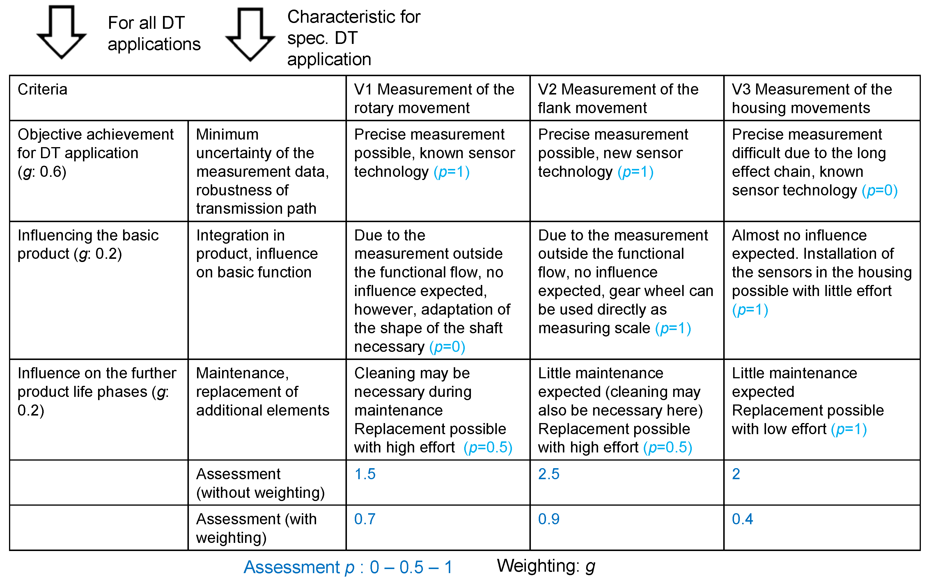
Application to the multi-stage gearbox: The general criteria under these categories are specific to the concrete product. The application of the evaluation for the gearbox example can be found in Figure 13 (DT for Digital Twin). The weightings are given as examples and must be applied in the specific context. Due to the strict requirements for measurement accuracy on the Digital Twin Solution and the low influence on the basic product as well as the expected low influences on the further life phases, V2 is chosen.
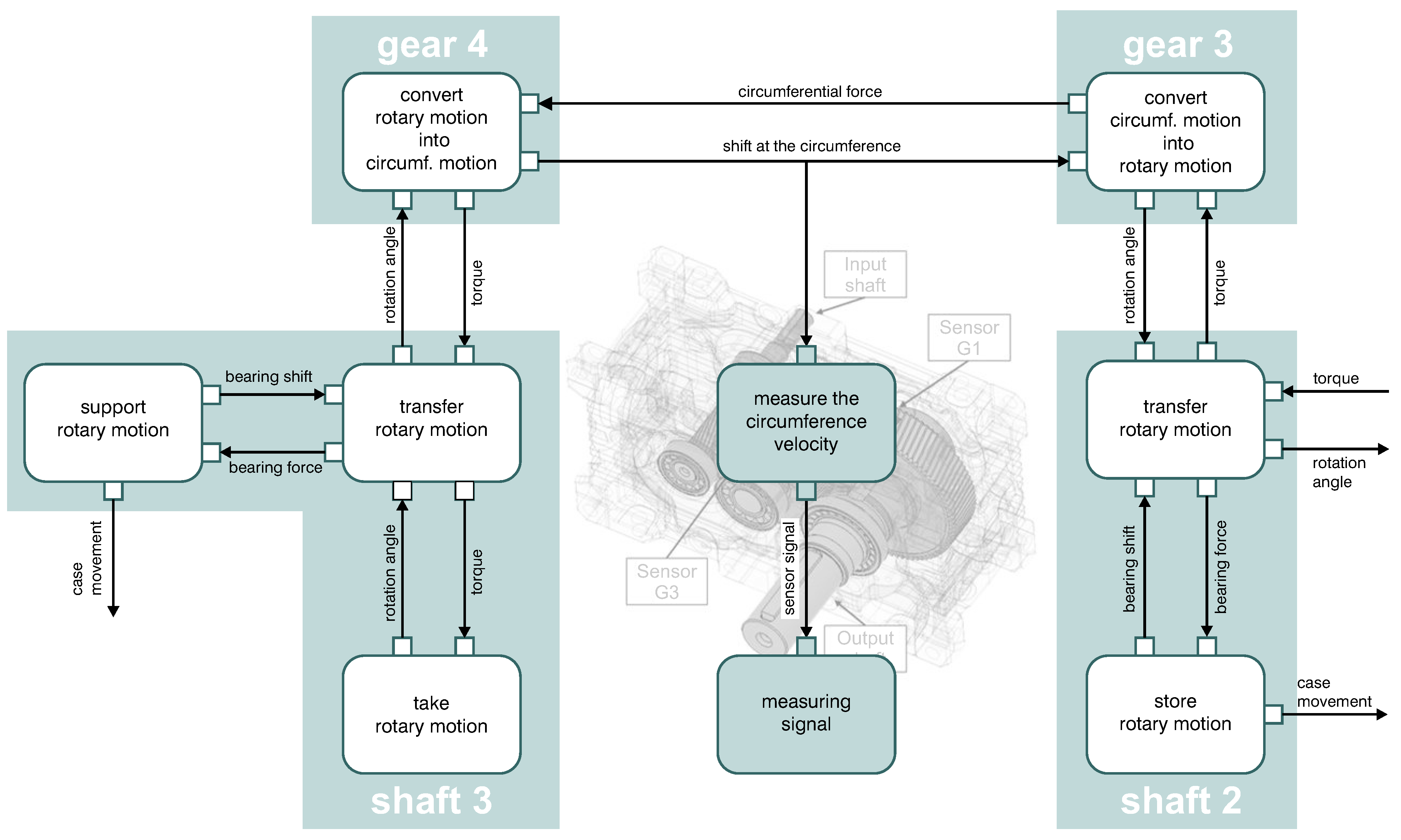
The selection of V2 in the detail of V2.2. with the measurement at gear 3 brings the extension of the cause-effect relationships (see Figure 14).

3.6. Impact of the Sensor Concept on the Digital Twin

After selecting and conceptualizing the sensor solution to fulfill the stakeholder demand and use cases, the Digital Twin has to be detailed. This involves answering the following questions:
  • In which way must the Digital Twin model be designed for data management and which functions must be implemented for the simulations as well as other necessary functions (e.g., for communication)?
  • What new insights can the model of the Digital Twin generate?
In addition, the data acquisition, processing, and evaluation must be detailed. The processing of the determined measurement data builds on the model selected in Section 3.2.
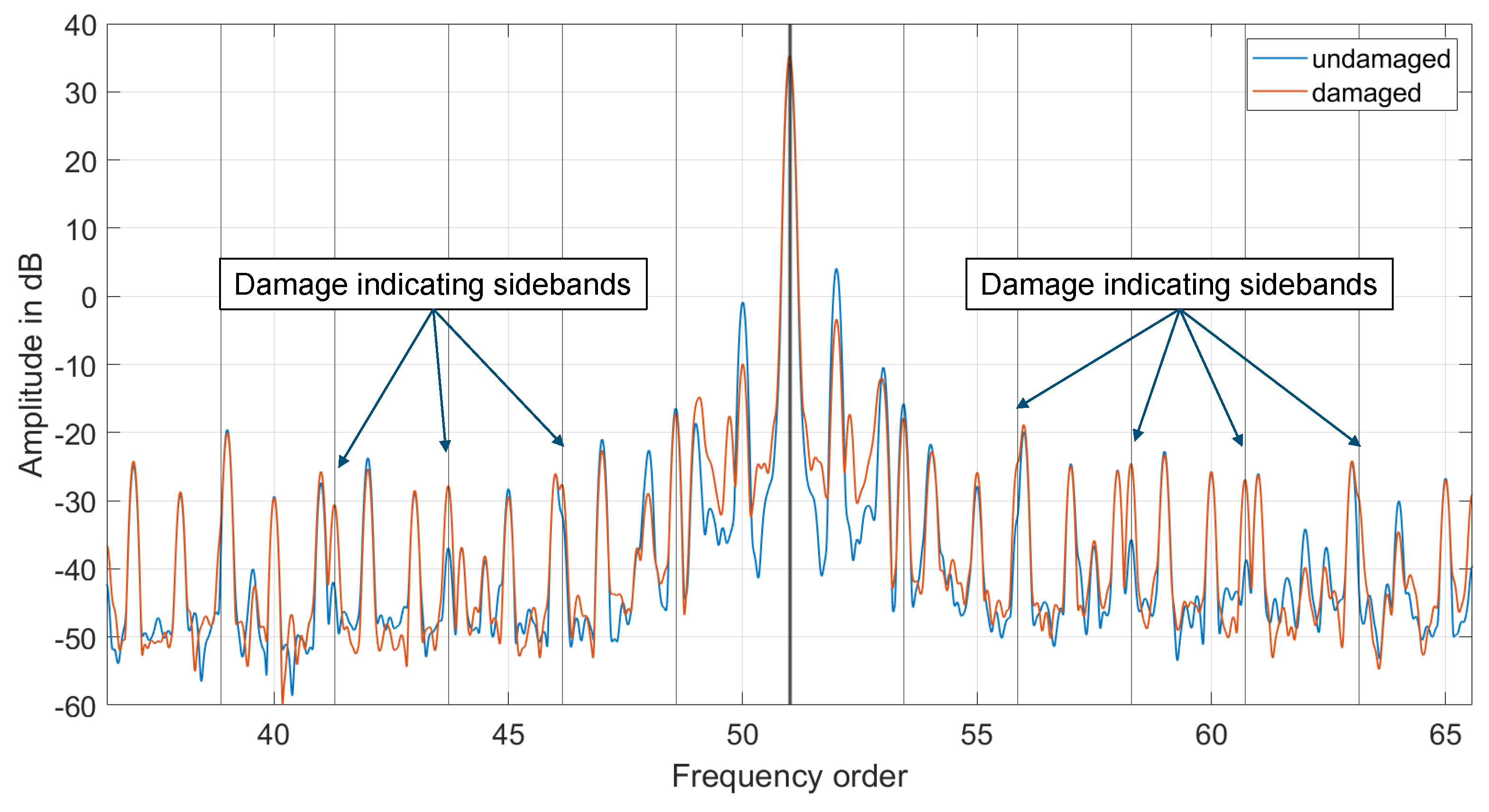
For the application to the multi-stage gearbox, the wear is to be determined. The primary measurand as the basis for the model is the flank movement of the gear. This can be used to calculate the gear wheel angle. With the measurement procedure, the flank movement can be measured, and thus also the speed. The sensors acquire one sine-like wave per tooth. The two sensor elements are 90° phase-shifted and with the atan2-function the angle is calculated from the raw signal. The calculations are carried out using Matlab R2019b. Damage, such as pitting on the tooth flank, leads to a change in the geometry and thus the stiffness. This change influences the tooth mesh and manifests itself in fluctuations in the rotational speed. These fluctuations can be identified with the measurement procedure. An analysis in the frequency domain is suitable. Therefore, the measured angle is converted to the frequency domain be the FFT function. The increase of the gear meshing frequencies and surrounding sidebands are an indicator of wear on the tooth flank. If these features (e.g., gear mesh frequency and sidebands) are extracted, this also leads to a significant reduction in the amount of data. Figure 15 shows a comparison of measurements in the undamaged and artificially damaged state of a pinion in the frequency order domain. It can be seen that the sidebands, which indicate a damage, are elevated due to the damage. Koch et al. [38] conducted a feasibility study using the described measurement concept. The shown data are taken from this data set [39]. In addition, the torque can be calculated via the twist between two measuring points and the stiffness in between. This makes it possible to use a wide variety of evaluation methods in the Digital Twin, e.g., the load can be monitored at any time and the service life of the gearbox already used can be calculated from this in order to plan further operating time and maintenance. For this purpose, service life models are to be created based on the existing DIN 3993 standards [40].
To use the sensor concept in conjunction with the Digital Twin, the evaluation models for fulfilling the use cases “Monitor Wear” must be created. Communication interfaces are to be implemented in the Digital Twin for this purpose.
For the use case “Monitor Wear”, in addition to the evaluation models that convert the measurement signal into a wear property, an operating strategy must also be designed so that a compromise can be made between the amount of data generated and the accuracy of the wear determination. Therefore, different strategies can be chosen:
1. 
Permanent measurement
2. 
Interval measurement with adaptive adjustment (depending on the operating parameters)
3. 
Interval measurement
The decision for an operating strategy depends on the specific application case of the gearbox. In addition, the sensors can also be monitored by the Digital Twin so that faulty measurement signals do not lead to an incorrect action, e.g., premature or delayed maintenance. When using multiple sensors, this can be performed via a plausibility check between the measurement signals. This can reduce the probability of failure. This shows very clearly that the interactions between the Digital and Real Twin must be analyzed and understood in every phase of life. To do this, all possible influences must be identified in advance and evaluation methods must be implemented.

4. Discussion and Conclusions

Digital Twins support numerous use cases in the life phases of the products. To ensure that the use cases can be implemented in a targeted manner, the Digital Twin Solution must be systematically conceptualized and designed. In this paper, a methodical approach for determining a target-oriented Digital Twin Solution is presented and applied to a multi-stage gearbox. By applying the methodical approach, a robust Digital Twin Solution can be found that supports the use cases, and does not influence the basic system of the Real Twin too much (according to the harmlessness condition of Hansen [41]). With the combination of effect chain analysis and detail sensor selection using the SuDE methodology, target-oriented measurement principles and positions can be determined for the relevant properties. With these methodological steps, an answer can be provided for the first research question (see Section 1). The subsequent systematic analysis of disturbance factors and influences on the Digital Twin Solution enables the robustness of the solution variants to be assessed and optimized. A multi-criteria evaluation with the use of application-specific criteria and criteria on further effects of the variants of the Digital Twin Solution enables the selection of an appropriate solution. This provides an answer to research question two. Based on the solution for extending the Real Twin, the modeling and data management of the Digital Twin can be concretized. In further research activities, the approach will be validated on additional applications and, if necessary, further detailed. Among other things, this concerns products in which the basic functions are not primarily realized via mechanical effects.

Author Contributions

Methodology, S.H., Y.K., P.W. and B.K.; Writing—original draft, S.H., Y.K., P.W. and B.K.; Writing—review and editing, S.H., Y.K., P.W., B.K., F.R., F.F. and E.K. All authors have read and agreed to the published version of the manuscript.

Funding

This research received no external funding.

Data Availability Statement

The research data used in this contribution is published and accessible [39].

Acknowledgments

We acknowledge support for the publication costs by the Open Access Publication Fund of the Technische Universität Ilmenau.

Conflicts of Interest

The authors declare no conflict of interest.

Abbreviations

The following abbreviations are used in this manuscript:
ADTAutonomous Digital Twin
DTDigital Twin
FFTFast Fourier Transform
IDTInformational Digital Twin
ScMEsensor-carrying machine elements
SDTSupporting Digital Twin
SiMESensor integrating Machine Elements
SMESensing machine elements
SuDESensor utilizable Design Elements
SuMESensory utilizable Machine Elements

References

  1. Bertoni, M.; Bertoni, A. Designing solutions with the product-service systems digital twin: What is now and what is next? Comput. Ind. 2022, 138, 103629. [Google Scholar] [CrossRef]
  2. Trauer, J.; Mutschler, M.; Mörtl, M.; Zimmermann, M. Challenges in Implementing Digital Twins—A Survey. In Proceedings of the ASME 2022 International Design Engineering Technical Conferences and Computers and Information in Engineering Conference, St. Louis, MO, USA, 14–17 August 2022. [Google Scholar]
  3. Schleich, B.; Anwer, N.; Mathieu, L.; Wartzack, S. Shaping the digital twin for design and production engineering. CIRP Ann. 2017, 66, 141–144. [Google Scholar] [CrossRef]
  4. Martinsson, J.; Panarotto, M.; Kokkolaras, M.; Isaksson, O. Exploring the potential of digital twin-driven design of aero-engine structures. In Proceedings of the 23rd International Conference on Engineering Design (ICED21), Gothenburg, Sweden, 16–20 August 2021. [Google Scholar]
  5. Jones, D.E.; Snider, C.; Kent, L.; Hicks, B. Early Stage Digital Twins for Early Stage Engineering Design. In Proceedings of the 21rd International Conference on Engineering Design (ICED19), Delft, The Netherlands, 5–8 August 2019. [Google Scholar]
  6. Koch, Y.; Husung, S.; Röhnert, F.; Mahboob, A.; Frank, M.G.; Kirchner, E. A Method for the Support of the Design for Digital Twin Solution and Its Application on a Gearbox System. In Proceedings of the International Design Conference—Deisgn 2022, Cavtat, Croatia, 23–26 May 2022; pp. 1609–1618. [Google Scholar]
  7. Wilking, F.; Schleich, B.; Wartzack, S. Digital Twins—Definitions, Classses and Business Scenarios for different Industry Sectors. In Proceedings of the 23rd International Conference on Engineering Design (ICED21), Gothenburg, Sweden, 16–20 August 2021; pp. 1293–1302. [Google Scholar]
  8. VDI 2206:2021; Development of Mechatronic and Cyber-Physical Systems. Beuth Publishing: Berlin, Germany, 2021.
  9. Eickhoff, T.; Forte, S.; Göbel, J. Approach for Developing Digital Twins of Smart Products Based on Linked Lifecycle Information. In Proceedings of the Internatinal Design Conference—Design 2022, Cavtat, Croatia, 23–26 May 2022; pp. 1559–1568. [Google Scholar]
  10. Röhm, B.; Emich, B.; Anderl, R. Approach of simulation data management for the application of the digital simulation twin. In Proceedings of the Procedia CIRP 100, Enschede, The Netherlands, 19–21 May 2021; pp. 421–426. [Google Scholar]
  11. Boss, B.; Malakuti, S.; Lin, S.; Usländer, T.; Clauer, E.; Hoffmeister, M.; Stojanovic, L.; Flubacher, B. Digital twin and asset administration shell concepts and application in the industrial internet and industrie 4.0: An industrial internet consortium and plattform industrie 4.0 joint whitepaper. Plattf. Ind. 2020, 4, 13–14. [Google Scholar]
  12. Moyne, J.; Qamsane, Y.; Balta, E.; Kovalenko, I.; Faris, J.; Barton, K.; Tilbury, D. A requirements driven digital twin framework: Specification and opportunities. IEEE Access 2020, 8, 107781–107801. [Google Scholar] [CrossRef]
  13. Trauer, J.; Schweigert-Recksiek, S.; Engel, C.; Spreitzer, K.; Zimmermann, M. What is a digital twin? Definitions and insights from an industrial case study in technical product development. In Proceedings of the Design Society: DESIGN Conference, Cavtat, Croatia, 26–29 October 2020; pp. 757–766. [Google Scholar]
  14. Anderl, R. Industrie 4.0—Technological approaches, use cases, and implementation. at-Automatisierungstechnik 2015, 63, 753–765. [Google Scholar] [CrossRef]
  15. Durão, L.F.; Haag, S.; Anderl, R.; Schützer, K.; Zancul, E. Digital twin requirements in the context of industry 4.0. In Proceedings of the 15th IFIP WG 5.1 International Conference, PLM 2018, Turin, Italy, 2–4 July 2018; pp. 204–214. [Google Scholar]
  16. Madni, A.M.; Madni, C.C.; Lucero, S.D. Leveraging Digital Twin Technology in Model-Based Systems Engineering. Systems 2019, 7, 7. [Google Scholar] [CrossRef]
  17. PlattformIndustrie 4.0. Details of the Asset Administration Shell. 2022. Available online: https://www.plattform-i40.de/IP/Redaktion/DE/Downloads/Publikation/Details_of_the_Asset_Administration_Shell_Part1_V3.html (accessed on 27 March 2023).
  18. Vorwerk-Handing, G.; Gwosch, T.; Schork, S.; Kirchner, E.; Matthiesen, S. Classification and examples of next generation machine elements. Forsch. Ingenieurwesen 2020, 84, 21–32. [Google Scholar] [CrossRef]
  19. Kraus, B.; Neu, M.; Kirchner, E. Sensing machine elements as enablers of comprehensive digitization—A review. In Proceedings of the 10th International Electric Drives Production Conference (EDPC), Ludwigsburg, Germany, 8–9 December 2020; pp. 1–8. [Google Scholar]
  20. Peters, J.; Ott, L.; Dörr, M.; Gwosch, T.; Matthiesen, S. Sensorintegrierende Zahnräder: Verschleißdetektion durch In-situ MEMS Beschleunigungssensoren. Forsch. Ingenieurwesen 2022, 86, 421. [Google Scholar] [CrossRef]
  21. Bonaiti, L.; Knoll, E.; Otto, M.; Gorla, C.; Stahl, K. The Effect of Sensor Integration on the Load Carrying Capacity of Gears. Machines 2022, 10, 888. [Google Scholar] [CrossRef]
  22. Harder, A.; Hausmann, M.; Kraus, B.; Kirchner, E.; Hasse, A. Sensory Utilizable Design Elements: Classifications, Applications and Challenges. Appl. Mech. 2022, 3, 160–173. [Google Scholar] [CrossRef]
  23. Kraus, B.; Schwind, J.V.; Kirchner, E. Development Method for Enabling the Utilisation of a Sensory Function in a Central Component Based on Its Physical Properties. In Proceedings of the Design Society, Cavtat, Croatia, 23–26 May 2022; pp. 1619–1628. [Google Scholar]
  24. Kraus, B.; Matzke, S.; Welzbacher, P.; Kirchner, E. Utilizing a graph data structure to model physical effects and dependencies between different physical variables for the systematic identification of sensory effects in design elements. In Proceedings of the 33rd Symposium Design for X (DFX2022), Hamburg, Germany, 22–23 September 2022; pp. 1–10. [Google Scholar]
  25. DIN. International Vocabulary of Metrology, 4th ed.; Beuth Wissen: Berlin, Germany, 2012. [Google Scholar]
  26. Drave, I.; Rumpe, B.; Wortmann, A.; Berroth, J.; Hoepfner, G.; Jacobs, G.; Spuetz, K.; Zerwas, T.; Guist, C.; Kohl, J. Modeling mechanical functional architectures in SysML. In Proceedings of the 23rd ACM/IEEE International Conference on Model Driven Engineering Languages and Systems, New York, NY, USA, 16–23 October 2020; pp. 79–89. [Google Scholar]
  27. Huth, T.; Inkermann, D.; Wilms, R.; Vietor, T. Model-based Process Engineering-An approach to integrated product system and process modelling. In Proceedings of the EMEASEC 2018/TdSE 2018, Berlin, Germany, 5–7 November 2018. [Google Scholar]
  28. Weber, C. CPM/PDD—An Extended Theoretical Approach to Modelling Products and Product Development Processes. In Proceedings of the 2nd German-Israeli Symposium on Advances in Methods and Systems for Development of Products and Processes, Tel Aviv, Israel, 7–8 July 2005; pp. 159–179. [Google Scholar]
  29. Brix, T.; Husung, S. Research and Teaching on Robust Design in early Design Phases, RD SIG Seminar Series. 2022. Available online: https://data.mendeley.com/datasets/n9pjyhxkht (accessed on 27 March 2023).
  30. Höhne, G.; Weber, C. Function and design of mechanical components in mechatronic systems (Invited Paper). In Proceedings of the 19th International Congress of Mechanical Engineering (COBEM 2007), Brasília, Brazil, 5–8 November 2007. [Google Scholar]
  31. Snowdon, J.C. Mechanical four-pole parameters and their application. J. Sound Vib. 1971, 15, 307–323. [Google Scholar] [CrossRef]
  32. Qurthobi, A.; Maskeliūnas, R.; Damaševičius, R. Detection of Mechanical Failures in Industrial Machines Using Overlapping Acoustic Anomalies: A Systematic Literature Review. Sensors 2022, 22, 3888. [Google Scholar] [CrossRef] [PubMed]
  33. Randall, R. Vibration-Based Condition Monitoring: Industrial, Aerospace and Automotive Applications; Wiley: Hoboken, NJ, USA, 2010. [Google Scholar]
  34. Welzbacher, P.; Vorwerk-Handing, G.; Kirchner, E. A control list for the systematic identification of disturbance factors. In Proceedings of the Design Society, 23rd International Conference on Engineering Design, Gothenburg, Sweden, 16–20 August 2021; Cambridge University Press: Cambridge, UK, 2021; pp. 51–60. [Google Scholar]
  35. Mathias, J.; Kloberdanz, H.; Engelhardt, R.; Birkhofer, H. Strategies and principles to design robust products. In Proceedings of the DESIGN 2010—The 11th International Design Conference, Dubrovnik, Croatia, 17–20 May 2010; pp. 341–350. [Google Scholar]
  36. Pahl, G.; Beitz, W.; Feldhusen, J.; Grote, K.H. Engineering Design A Systematic Approach, 3rd ed.; Springer: London, UK, 2007; pp. 1–25. [Google Scholar]
  37. VDI 2225; Sheet1: Design Engineering Methodics—Engineering Design at Optimum Cost—Simplified Calculation of Costs. VDI: Dusseldorf, Germany, 1997.
  38. Koch, Y.; Martin, G.; Kirchner, E.; Quirnheim Pais, D.; Slatter, R. Feasibility study of measuring instantaneous angular speed of helical gears with magnetoresistive sensors. Forsch. Ingenieurwesen 2022, 86, 451–459. [Google Scholar] [CrossRef]
  39. Koch, Y.; Martin, G.; Kirchner, E.; Quirnheim Pais, D.; Rauber, L.; Lenze, T.; Slatter, R. Measurement of Instantaneous Angular Speed in a Helical Gear Box using Magnetoresistive Sensors. Available online: https://tudatalib.ulb.tu-darmstadt.de/handle/tudatalib/2982?locale-attribute=en (accessed on 25 April 2023).
  40. DIN 3993-1:1981-08; Geometrical Design of Cylindrical Internal Involute Gear Pairs—Basic Rules. Beuth Publishing: Berlin, Germany, 1981.
  41. Hansen, F. Adjustment of Precision Mechanisms; Iliffe Books: London, UK, 1970. [Google Scholar]
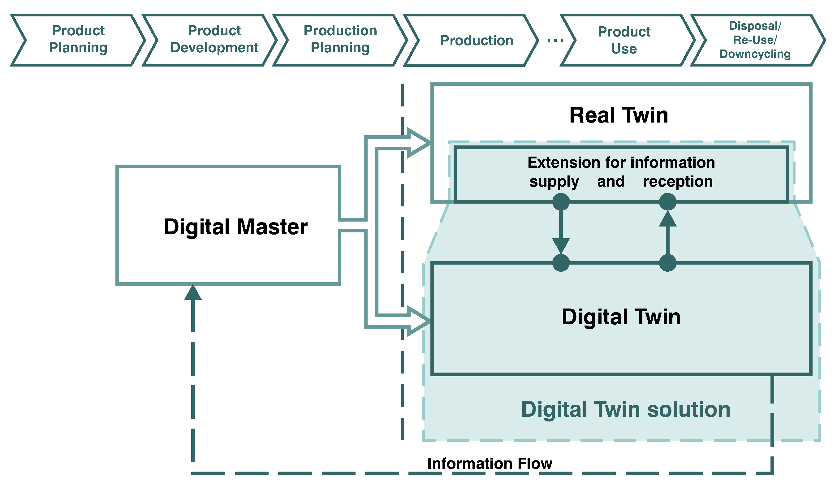
Figure 1. Digital Twin Solution [6].
Systems 11 00227 g001
Figure 2. Aspects of the Digital Twin Solution and focus of the paper.
Systems 11 00227 g002
Figure 3. Structure of the approach to design the Digital Twin Solution [6].
Systems 11 00227 g003
Figure 4. Detailed methodical steps of the approach with respective results (work products).
Systems 11 00227 g004
Figure 5. Usecases and relevant product properties.
Systems 11 00227 g005
Figure 6. Direct and simulation-specific properties and characteristics.
Systems 11 00227 g006
Figure 7. Function of the system depending on the intended and unintended interactions and internal characteristics [29].
Systems 11 00227 g007
Figure 8. Four-pole modeling of a transmission system with the context [30].
Systems 11 00227 g008
Figure 9. Four-pole model of the gearbox incl. the interactions between the gearbox components (simplified visualization—partially depicted as multi-poles in the figure).
Systems 11 00227 g009
Figure 10. Variants of the measurement to determine the deviation of the shape of the tooth flanks (V1–V3).
Systems 11 00227 g010
Figure 11. Excerpt of the filled-in disturbance factor control list (cf. [34]).
Systems 11 00227 g011
Figure 12. Measures to control the disturbance [29].
Systems 11 00227 g012
Figure 13. Evaluation ofthe solution variants (excerpt, simplified).
Systems 11 00227 g013
Figure 14. Model of the gearbox after extension by the measurement functions.
Systems 11 00227 g014
Figure 15. Comparison of the frequency order range of the measured angular velocity in an undamaged and artificially damaged condition.
Systems 11 00227 g015
Disclaimer/Publisher’s Note: The statements, opinions and data contained in all publications are solely those of the individual author(s) and contributor(s) and not of MDPI and/or the editor(s). MDPI and/or the editor(s) disclaim responsibility for any injury to people or property resulting from any ideas, methods, instructions or products referred to in the content.