1. Introduction
Artificial intelligence has been used for applications, including robotics [
1], advertising [
2], personal digital assistants [
3], college admissions [
4], operations management [
5], gaming [
6], determining borrowers credit worthiness [
7,
8], performing surgery [
9,
10], and scientific experimentation [
11]. It has been identified as a source of future cyber threats [
12] and a key mechanism to detect [
13] and respond to them. Its use is pervasive in modern society.
One factor that inhibits the utility of artificial intelligence systems is humans’ trust in them. To this end, a key issue with some systems is that humans cannot readily understand techniques’ operations and how particular decisions are made. This is particularly vexing for individuals impacted by these decisions [
14]. So-called “explainable” techniques [
15,
16] have been developed in response to these concerns.
This paper seeks to solve the problem of developing a time-definite, defensible, and low-power/low-cost artificial intelligence technique that is suitable for applications such as cyber-physical system command. Many existing state-of-the-art solutions, which are implemented as software running on general purpose computer systems, are limited by the power and hardware cost of their host hardware and the time variability introduced by algorithms’ iterative processing. Existing hardware implementations (see, e.g., [
17]) are responsive to power [
18] and cost limitations and some reduce time variability. However, no defensible hardware implementation has been previously produced.
Defensible artificial intelligence, introduced in [
19], goes beyond simply requiring the technique’s operations to be understood. It requires the technique to be demonstrably making the correct decision while still having the capability to learn from training and operations. Learning, however, is what creates the potential for artificial intelligence techniques to become “algorithms of oppression” [
20] and associate outcomes with confounded characteristics, potentially illegally. Neural networks, in particular, are problematic as they have no specific meaning [
21]; rather, they simply learn whatever associations may be present. Their decisions—also problematically—for a given set of inputs, could rapidly change with additional training.
The defensible artificial intelligence system, which was introduced in [
19], demonstrated in [
22], and refined in [
23,
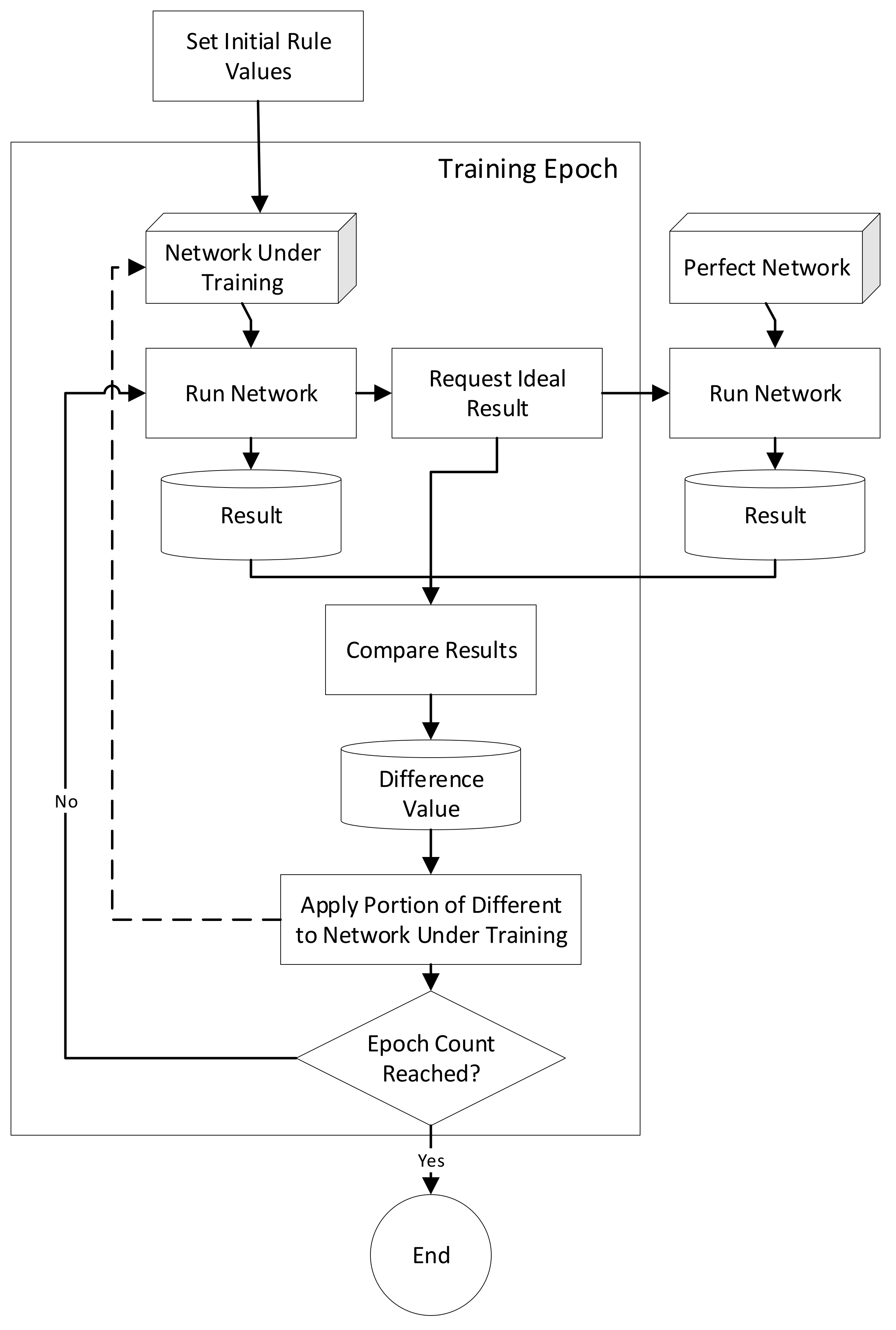
24], utilizes expert systems as the basis of its design. Users begin by developing a logically valid network. Then, rule weights (which are floating point numbers between 0 and 1) are optimized using a gradient descent approach, similar to what is commonly used for neural networks.
Expert systems are an early form of artificial intelligence. They began with the Dendral and Mycin [
25] systems in the 1960s and 1970s. Because of their design, they are inherently understandable. They utilize a rule-fact network with every fact, generally, having a specific meaning and every rule being logically valid. While they were initially designed to emulate the decisions an expert would make, they have grown and been used in other areas. Examples include control systems [
26], facial expression analysis [
27], and power system [
28] analysis.
Versions of expert systems that use fuzzy logic have been proposed. They use fuzzy set concepts [
29] and represent rules’ and facts’ value uncertainty. A taxonomy for these systems was defined by Mitra and Pal [
30], who described a “knowledge-based connectionist expert system” that begins with “crude rules”, stores these as connection weights within a neural network, and uses training to produce refined rules. The floating point rule weighting values follow this conceptual model.
Both expert systems and neural networks have typically been implemented using an iterative algorithm. Expert systems use iteration for rule activation and neural networks utilize iteration for training. However, this is problematic for several reasons. First, the network’s output may differ based on the order that rules are selected for execution. The iteration of the expert system’s rule processing engine also means that the decision-making time can only be predicted, limiting the utility of expert systems for controlling robotics and other real-time applications.
The limitation of processing uncertainty can be removed by implementing the system in hardware, which allows rule execution to be performed in parallel. In [
31,
32], the use of a hardware-based (instead of a software-based) rule-fact network was proposed; however, these papers did not implement or test such a system. A basic hardware Boolean expert system was implemented previously [
33] and its performance was characterized, showing that it had a relatively consistent operating speed and high accuracy. These factors, and its lower (as compared to a general-purpose computer) cost, made hardware implementation potentially beneficial for a number of different types of applications.
In this paper, the concept of hardware-based expert systems is further developed through the creation of a gradient descent trained version, which operates conceptually similarly to a neural network. While hardware AI systems have been developed previously, no defensible AI hardware system has been previously created. This paper describes the design of a hardware-implemented gradient descent trainable expert system and discusses its implementation. The efficacy and performance of hardware-based expert systems’ gradient descent-trainable networks are also explored and discussed.
In
Section 2, this paper continues with a review of prior work, which provides a foundation for this paper.
Section 3 presents the design of the system that was utilized for the experimentation presented herein.
Section 4, then, presents the experimental design used for this experimentation. Next,
Section 5 presents and analyzes the data collected using this system. Following this, in
Section 6, several applications for the proposed system are discussed. Finally, the paper concludes with a discussion of key conclusions and future work in
Section 7.
4. Experimental Design
The experimentation that provides the data analyzed herein was conducted in several parts. First, individual components and boards were analyzed using standard techniques, which are briefly described before the data collected from this is presented in
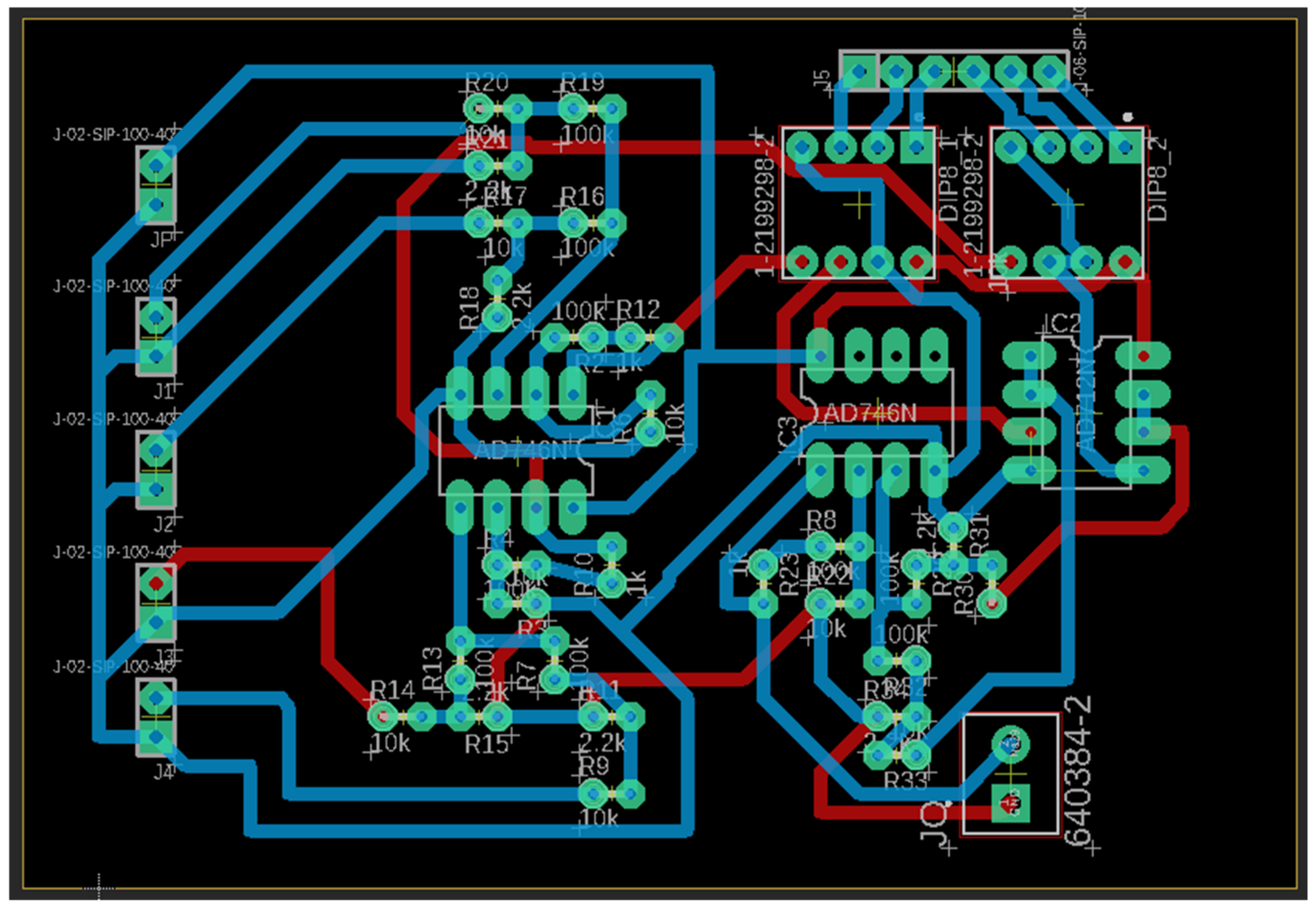
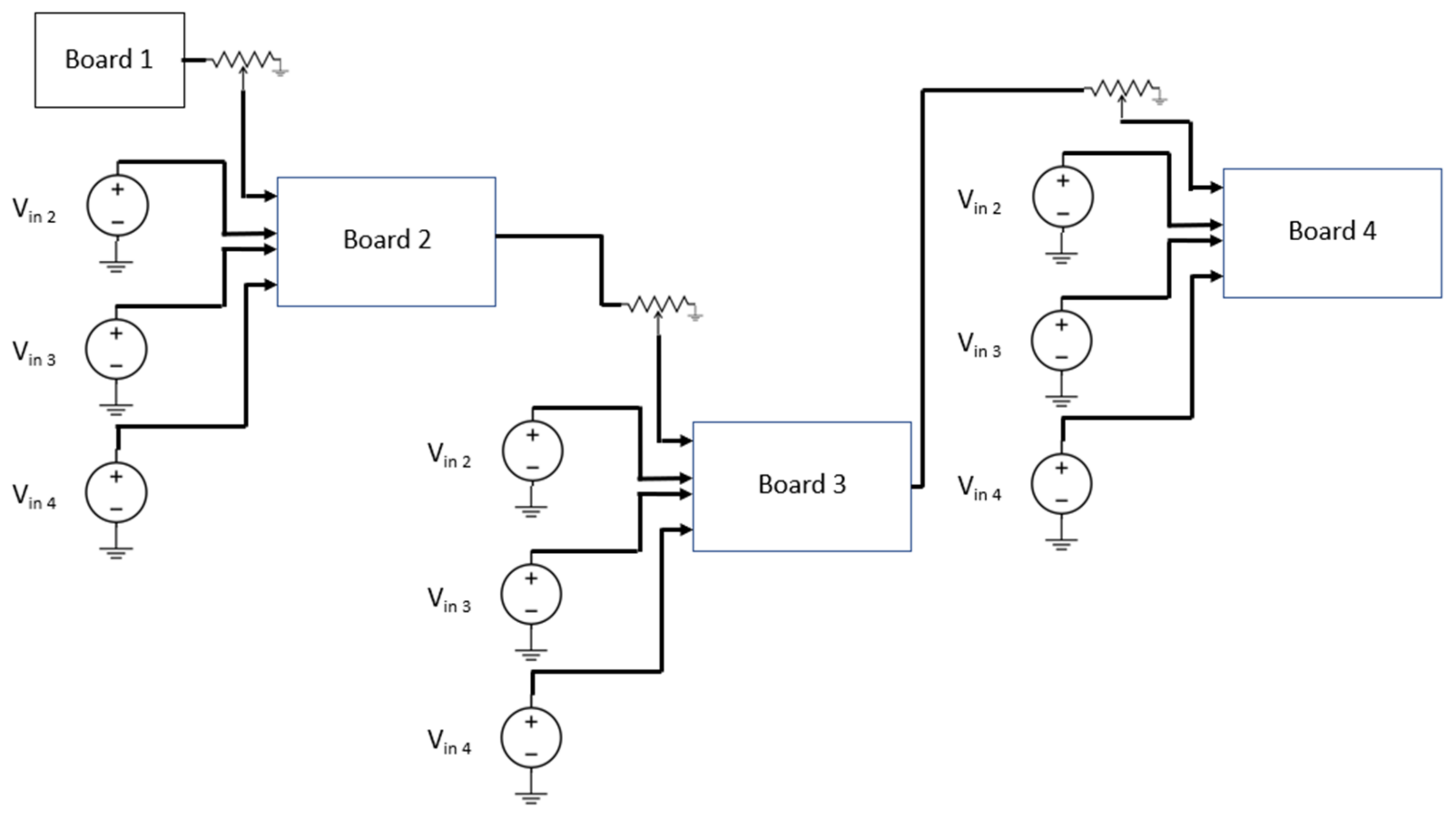
Section 5. Following this, an experiment was conducted using basic GDES networks. These were created using two configurations of four HGDES boards (each of which has three GDES nodes on them). Each of these boards has a set of four inputs labeled V
1(top) to V
4(bottom). In configuration 1, which is presented in
Figure 9, the outputs of the three boards are used as input to the fourth board. Potentiometers are used to provide the weightings between the boards (controlling the input voltages of each of these four inputs to the first layer of adder circuits on the fourth board). The output of board 4 is the final system output. In this configuration, boards 1, 2, and 3 each have four individual inputs, which can be supplied with any voltage supply, which follows the previously described circuit constraints.
In the second configuration, shown in
Figure 10, board 1 is connected to four independent inputs (not shown in the figure), as was the case in configuration 1. Boards 2, 3, and 4, receive their first input from the output of the previous board and the other inputs are connected to independent voltage sources.
As previously noted, the power supplies’ voltage regulation was used to provide the inputs’ weighting for the initial boards, under the first configuration, for experimental purposes. For the second configuration, the power supplies’ voltage regulation provided the weighting for all inputs for board 1 and the second through fourth inputs for boards 2, 3, and 4.
5. Data and Analysis
This section presents the data that was collected and analysis of it. First, basic analysis of the performance of potentiometer chips used for this implementation and the basic three-node board is provided. Next, analysis of the combined (multi-node) circuits is presented. Finally, a basic hardware gradient descent expert system, including its training and performance, is analyzed.
5.1. Basic Circuit Analysis
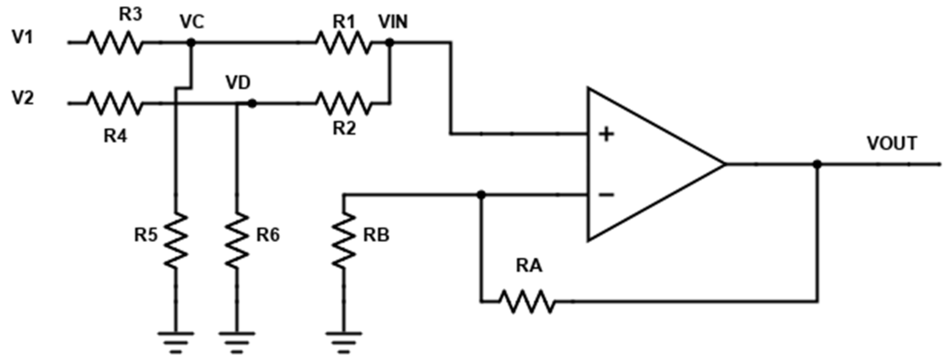
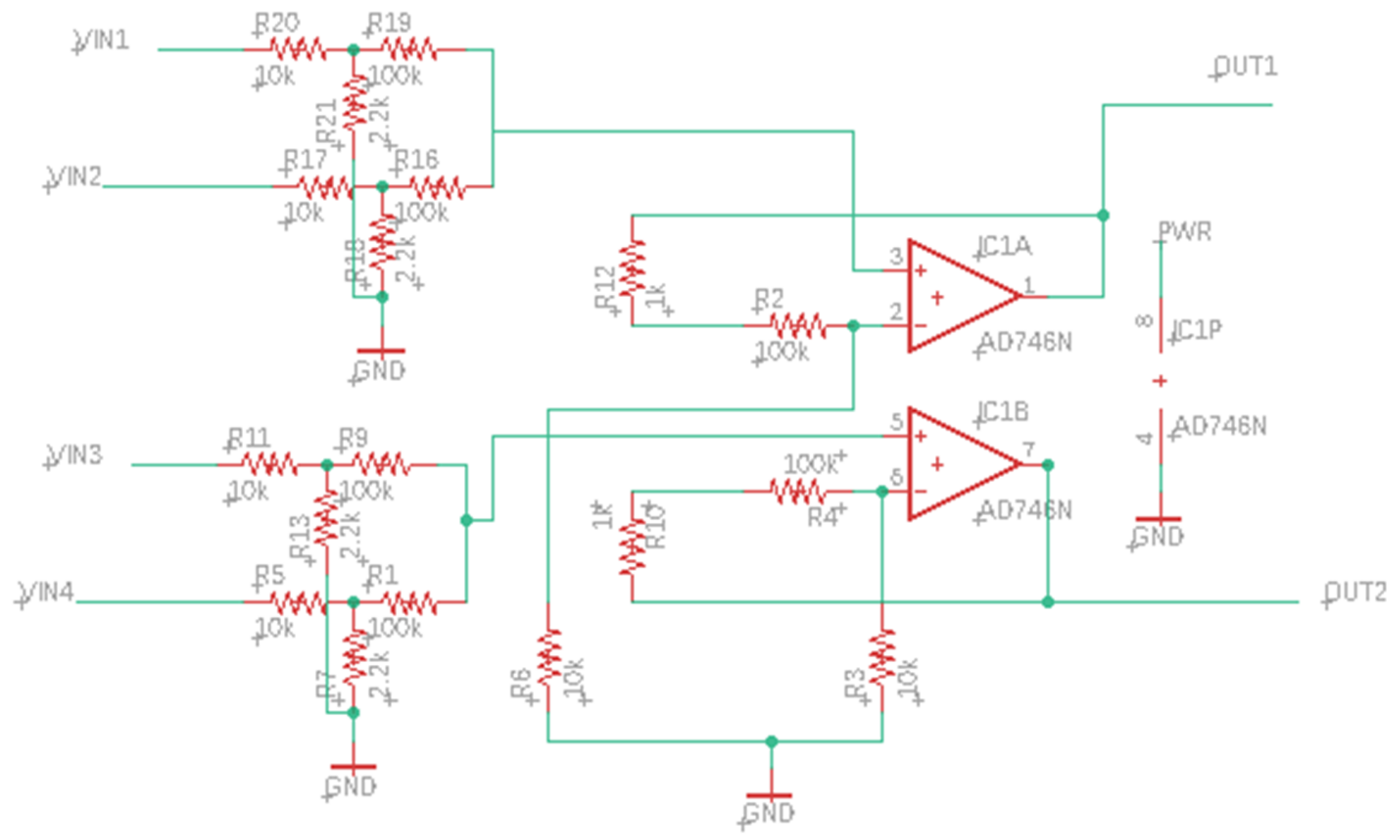
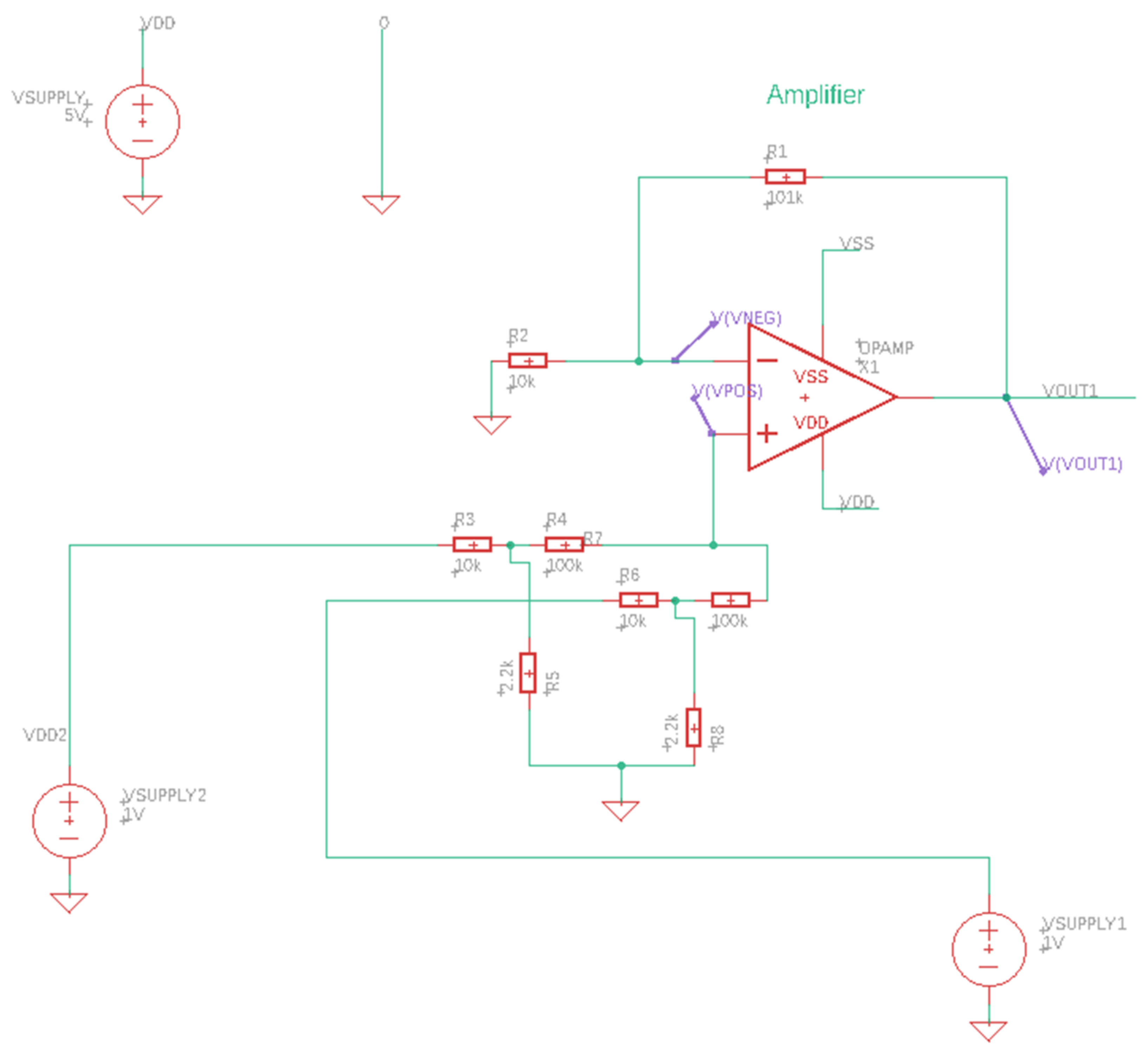
The first testing that was conducted was to validate the accuracy of the circuit design. This was conducted using the built-in SPICE simulation capability in the Eagle PCB Design software. The circuit was implemented using the OP AMP-based adders and potentiometer-based voltage divider circuits, as previously discussed.
The first simulation, shown in
Figure 11, tested the efficacy of a single OP AMP-based adder circuit using SPICE compatible components from the default ngspice library.
This simulation tested what level of error could occur, given different inputs to the adder circuit, which would introduce error into the result of the HGDES system. The results of this testing are recorded in
Table 1.
In most cases, the level of error was minimal. The largest error was seen with the V
in1 = 1, V
in2 = 1 case, where a greater level of error was present. The results verify that the design of the adder circuit schematic is correct, acceptable for most uses, and operates as described in
Section 3.2.
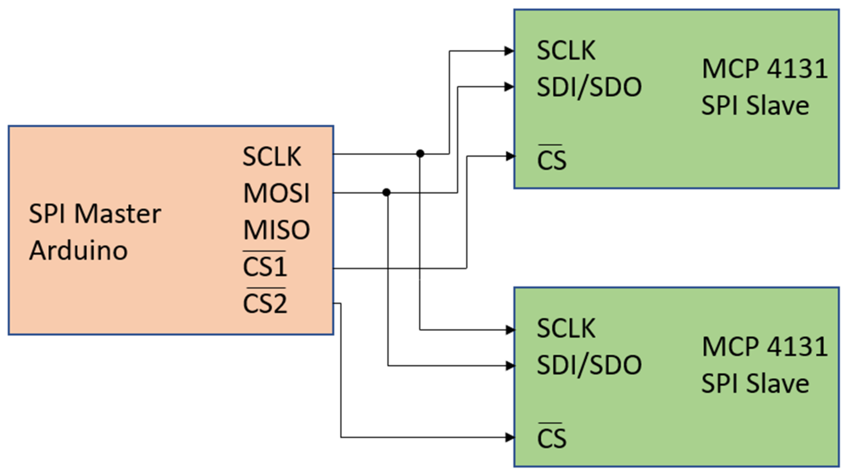
The potentiometer IC-based voltage divider circuit cannot be simulated using this simulation software, as it is operated using an Arduino microcontroller, which is not supported by the software. A hardware test of the MCP 4131 digital potentiometer IC was, thus, performed to characterize the values of resistance that it provides across the first two terminals of the potentiometer, given different input settings. These results are shown in
Table 2. Note that the third column “Ratio” is the ratio of the resistance between terminals 1–2 and terminals 3–4 of the potentiometers and is also the number by which the input voltage of the potentiometers is multiplied.
Next, the individual boards were tested to demonstrate the efficacy of the HGDES nodes and to verify their functionality.
Table 3,
Table 4,
Table 5 and
Table 6 present the results of the testing for boards 1 to 4, respectively.
The error levels present in the boards are quite limited (ranging from 0.002 to 0.185, with an apparent anomaly of almost a volt error in once instance). These are within acceptable levels of error for many, if not most, applications.
5.2. Combined Circuit Analysis
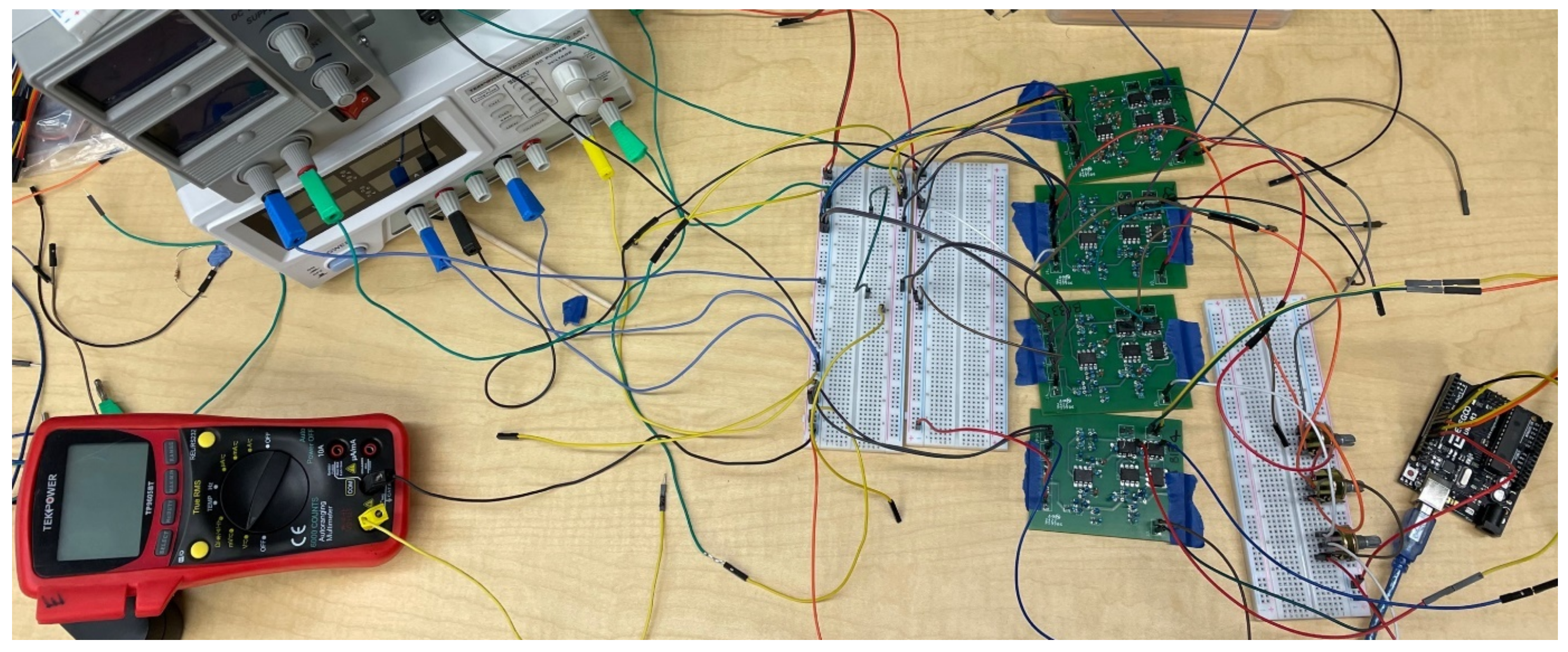
Next, testing was conducted using multiple boards in the configurations described in
Section 4. The performance of these multi-board configurations was assessed. This testing was conducted using the experimental setup (with varying wiring between the two configurations) shown in
Figure 12.
To test the multi-board configurations, pre-weighted inputs were supplied using voltage-regulated power supplies. The values of these supply voltages for the 11 tests are provided in
Table 7. Note that a limited amount of error, not considered in this table, was introduced by the voltage sources. This is anticipated to be less than ±0.1 V. The potentiometer settings used for the 11 tests are presented in
Table 8.
Based on the input voltages and potentiometer settings presented in
Table 7 and
Table 8, the ideal output values were calculated. These are presented in
Table 9. This table also includes the actual output values that were measured, using a digital multi-meter, from the hardware circuits. The percentage error was also calculated. These error values ranged from 0.02% to 2.63%. This level of error is tolerable for many, if not most, applications of this system.
Experimentation was also conducted using the second network configuration presented in
Section 4. The input voltages used for the 10 tests for this configuration are presented in
Table 10 and the potentiometer settings used for these tests are presented in
Table 11. Note that a limited amount of error, not considered in
Table 10, was introduced by the voltage sources. This is anticipated to be less than ±0.1 V.
Based on the voltage inputs and potentiometer settings provided in
Table 10 and
Table 11, the ideal output values were again computed. These are presented in
Table 12. The actual output values, collected using a digital multi-meter, are also presented in this table and the level of error was again calculated. The error level for this (longer) configuration ranged from 0.50% to 1.89%. Notably, the range of error closes somewhat. These error levels are, similarly, within the range acceptable for many, if not most, applications. Additionally, this testing demonstrates that error does not increase dramatically (average error increases from 0.94% to 1.03%) with more layers of nodes, which is critical to implementing more complex HGDES networks.
5.3. Training and Hardware Implementation
At present, the HGDES system relies upon the software implementation for its training operations, which generate the weighting values that are used as part of the HGDES networks. The digital implementation of the GDES system does not introduce error as part of the presentation function (which is the capability currently implemented via the HGDES system); however, its training mechanism is not perfect and introduces error. The error levels of the base system (without incorporating error reduction mechanisms) ranged from 5.2% to 8.3% [
19], meaning that the training error will dominate the hardware implementation error. Even with error reduction, which showed potential to reduce the upper end of this range down to 5.5% [
24], the training error would still be approximately 5 times greater than the hardware implementation presentation error.
Notably, the benefit of the hardware implementation, in terms of processing performance, is significant. It reduces the speed of processing from multiple iterations of network processing to the speed of the critical (longest time-wise) path of IC’s operating speeds. The ICs operate, inherently, in parallel while the software implementation must perform these same functions sequentially. Because of this, the level of benefit enjoyed will vary notably by network design. The assessment of this, with larger networks, is a planned area of future work.
In addition to the overall speed benefit, the hardware implementation will always process (for a given network) in the same amount of time. This is critical to time-sensitive applications, such as robotics, where decisions must be made within timeframes dictated by their real-world needs (e.g., the time between a robot sensing something up ahead and reaching its location). Thus, the hardware implementation will be suitable for some applications where a variable processing time software-based system would not be.
The hardware-based system also enjoys power consumption and cost-based benefits, as compared to operations on a general-purpose computer. For example, a laptop-based solution (such as what was used for testing) might cost hundreds of dollars and consume 20–50 watts of power [
87]. The test boards cost less than
$50 each (which would be further reduced significantly, on a per-GDES node basis, by the use of larger boards with more nodes on them and through mass production) and used only a small fraction (only about 3.475 micro amps) of the power [
88,
89]. Additional power savings are also enjoyed due to the fact that the HGDES system can be powered up, have its potentiometer values set, have needed tests run, and be powered-down, without requiring the boot-up and shut-down phases (introducing both a time and power cost) of conventional computers.
7. Conclusions and Future Work
This paper has presented initial work on the implementation of a hardware-based implementation of a gradient-descent trained expert system. It has shown that the previously software-based GDES nodes can be readily implemented in hardware and an analog signal, voltage, can be sent between them as data. It has shown that the required circuits can be developed with a low level of data loss (an average of approximately 1%), making them suitable for many—if not most—applications. Further, it has discussed the speed, power reduction, and cost reduction benefits of this implementation approach.
Notably, the proposed approach also provides a time-determinism benefit as well, as the hardware-implemented GDES system operates within an a priori known amount of time (which does vary by GDES network). This makes the system suitable for applications that require real-time or near real-time processing, such as robotics. In many cases, unknown duration iterative-based processes (such as software-based GDES) cannot be used for real-time command or require compensation for potential processing delays via using hardware with capabilities that far exceed the typical needs (but are projected to be sufficient for worst case scenarios). Hardware-based GDES, thus, would be suitable for various real-world applications that software-based GDES would potentially either not be usable for or for which it would require additional hardware capabilities.
Based on this initial work, a number of areas of future work are planned. The implementation and testing of larger networks is one area of planned future work. With these larger networks, the potential for the training process to take the hardware implementation error into account when training will be assessed. A second area of potential future work is to develop a hardware-based training mechanism.
Overall, the work presented herein has demonstrated the potential efficacy of hardware implementation of the GDES system and its effectiveness and suitability for many applications. This initial work demonstrates the value of the system and serves as a potential justification for future work in the areas mentioned above, which will further advance the system to be ready for practical use.
