Article

Experimental Study on Evaluation of Replacing Minimum Web Reinforcement with Discrete Fibers in RC Deep Beams

by
Murali Sagar Varma Sagi
1,
Chandrashekhar Lakavath
1,
S. Suriya Prakash
1 and
Akanshu Sharma
2,*
1
Department of Civil Engineering, Indian Institute of Technology Hyderabad, Sangareddy 502285, India
2
Lyles School of Civil Engineering, Purdue University, West Lafayette, IN 47907-2051, USA
*
Author to whom correspondence should be addressed.
Fibers 2021, 9(11), 73; https://doi.org/10.3390/fib9110073
Submission received: 14 October 2021 / Revised: 1 November 2021 / Accepted: 2 November 2021 / Published: 11 November 2021
(This article belongs to the Topic Fiber-Reinforced Cementitious Composites)

Abstract

:
This study investigates the possibility of replacing the minimum web reinforcement in deep beams with discrete fibers. Additionally, the equivalent dosage of fibers required to obtain similar performance of the deep beam with minimum web reinforcement is investigated. Deep beams made of plain concrete with no fibers, beams with minimum web reinforcement as per AASHTO LFRD recommendations (0.3% in both horizontal and vertical), and with a 0.5% volume fraction of steel, macro-synthetic and hybrid fibers are tested at a shear span to height ratio (a/h) of one. Test results show that the presence of 0.3% web reinforcement in horizontal and vertical directions increased the peak load by 25% compared to the plain concrete beams. However, it did not significantly change the first diagonal crack load. With the addition of 0.5% of steel, macro-synthetic and hybrid fibers, the peak load increased by 49%, 42%, and 63%, respectively, compared to the plain concrete specimen. The addition of steel fibers significantly improved the first cracking load. In contrast, macro-synthetic fibers did not affect the first cracking load but improved the ductility with higher deflections at peak. Hybridization of steel and macro synthetic fibers showed improved performance compared to the individual fibers of the same volume in peak load and ductility. Test results showed that a 0.5% volume fraction of discrete macro steel or synthetic or hybrid fibers can be used to completely replace the minimum web reinforcement (0.3% in both directions).

1. Introduction

Reinforced concrete (RC) deep beams are commonly used in tall buildings, bridges, and marine structures. Deep beams used as transfer girder in framed structure is shown in Figure 1. Deep beams have significantly higher shear capacity than slender RC beams due to their small shear span-to-effective depth ratio (a/d ≤ 2.0), where a is shear span of the beam and d is the effective depth. Higher strength in deep beams is possible due to the arching action, which leads to high-stress concentrations and non-linear strain distribution. Therefore, Bernoulli’s hypothesis of linear strain distribution is no longer valid [1,2] in the analysis of RC deep beams. Hence, the disturbed region of the deep beam is designed based on empirical methods or thumb rules. The strut and tie method (STM) is an alternative method to the empirical methods [3,4,5]. Similarly, the STM method is included in international code provisions like American code (ACI-318-19) [6], Canadian code (CSA-A23.3-14) [7], Australian code (AS 5100.5) [8] and Eurocode (EC2:2004) [9]. The STM assumes that the load is transferred to supports by inclined struts. The shear force is transferred by inclined concrete strut rather than the shearing force, hence significantly increasing the shear strength of the beam.
Generally, the shear strength of deep beams depends on the strength of the diagonal concrete strut if local failures in the nodes are prevented. This is due to transverse tensile strain induced by the strain within the longitudinal steel reinforcement as stated by the modified compression field theory. The presence of transverse tensile strain significantly reduces the effective compressive strength of the inclined strut due to the softening effect, and the same is illustrated in Figure 2. Due to this, the codes always suggest some minimum web reinforcement in the strut region to reduce compressive strength due to transverse tension.

1.1. Minimum Web Reinforcement

In deep beams, the minimum web shear reinforcement requirement depends on the design specification and procedure followed by the designer. In a few code provisions, the guidelines for the minimum web shear reinforcement are not clearly stated. Similarly, it is not clear whether the minimum web reinforcement provision is to achieve higher ultimate capacity by resisting the transverse tension developed in the diagonal strut region or to ensure the serviceability requirement such as the crack widths being within the acceptable limits. In AASHTO LRFD 2012 [10], for deep beam design, two different requirements exist for minimum web reinforcement. The first one is in the strut-and-tie model section of the specification: an orthogonal grid of reinforcement of 0.3% concrete area is required at each face. The second one is in the commentary section of the specification: the minimum web reinforcement is to ensure the ductility and to control the crack width by redistributing the internal stresses. Based on these statements, it is clearly understood that both strength and serviceability conditions were considered for minimum web shear reinforcement provision. Similarly, according to both the Canadian Building code (CSA A23.3-04) [7] and Eurocode (BS EN1992-1-1) [9] provisions, the minimum orthogonal grid of reinforcement of 0.2% gross concrete area needs to be provided at each face in deep beams.
According to ACI 318-19 [6] provision, the minimum web shear reinforcement is considered in STM by efficiency factor βs. A βs of 0.75 is used if 0.25% of the orthogonal grid or 0.25% net effective reinforcement ratio normal to the strut axis exist. Suppose the designer chose not to provide any web reinforcement, reduction in the strut capacity and brittle failure is accounted for by using a low-efficiency factor (βs) of 0.45. Some researchers [11,12,13] have observed that inclined strut regions without web reinforcement in the deep beams should not be permitted regardless of the efficiency factor. Additionally, they suggested that minimum web reinforcement is also used to compensate for the effects of temperature, restrained shrinkage, and others which may not be explicitly considered. Though there is no consensus in the design codes [6,7,8,9] or the literature [12,13,14], the minimum web reinforcement seems essential.

1.2. Discrete Fibers in Concrete

The popularity of fiber reinforced concrete (FRC) construction is increasing day by day. Previous studies on FRC highlighted the beneficial effects of fibers on improving the performance of concrete at both materials [15,16,17,18,19] and member level [20,21,22,23,24]. Many researchers [20,25,26,27,28,29,30] observed significant improvement in shear capacity due to the addition of steel fibers by delaying the crack widening and propagation through bridging action. Synthetic fibers such as polyolefin-based macro-synthetic fibers can also improve the structural performance of concrete, addressing the adverse effects of steel fibers, such as reduced workability and durability issues due to corrosion [29,31,32,33]. Past studies [16,34,35,36,37,38,39] have shown that synthetic fiber reinforced concrete (SynFRC) effectively improves tensile behavior, especially in the post-peak. With improved fracture behavior and crack control due to the addition of discrete fibers, web reinforcement requirements in the deep beams may be reduced or completely replaced with discrete fibers in the concrete.
Several researchers studied the effect of adding discrete steel fibers to the concrete in deep beams and found that ultimate shear capacity is significantly improved [40,41,42]. Beshara et al. [43] studied the effect of different parameters of steel fibers on response characteristics of deep beams having web reinforcements. They found that increase in the fiber volume content or fiber aspect ratio leads to an increase in the ultimate load, first diagonal cracking load, and displacement ductility of the deep beams. Kaize Ma et al. [44] studied the shear behavior of deep beams with a hybrid combination of macro and micro steel fibers and different amounts of web reinforcements. Few studies in the past [42,45,46,47,48] have focused on completely replacing the minimum web reinforcement in deep beams using steel fibers. Additionally, the effect of macro synthetic fibers on the behavior of deep beams at a low a/d ratio has not been studied in the past. Therefore, the possibility of replacing minimum web reinforcement in the deep beams with discrete steel or macro-synthetic or hybrid fibers, at a very low a/h ratio of one, is explored in this study. A minimum web reinforcement suggested by AASHTO LRFD [10] specifications (orthogonal grid of 0.3% web area) is considered in this study for comparison with FRC deep beams.

2. Research Significance and Objectives

The focus of this study is to evaluate the possibility of replacing minimum web reinforcement in deep beams with randomly distributed macro fibers for similar or improved performance. The specific objectives of this study are to evaluate the following:
  • To evaluate the effect of minimum web reinforcement on the shear behavior of deep beams.
  • To understand the effect of steel, macro-synthetic and hybrid fibers on the shear behavior of deep beams.
  • To evaluate the possibility of completely replacing minimum web reinforcement with discrete fibers in concrete.
  • To compare the change in the shear failure modes of deep beams reinforced with different fibers and minimum web shear reinforcement using the digital image correlation technique (DIC).
RC deep beams are tested at a shear span to depth (a/h) ratio equal to one. The variables considered are the 0.5% volume fractions of macro hooked-ended steel fibers (SF), macro synthetic fibers (MSF), and hybrid fibers (0.25%SF + 0.25%MSF). To compare the performance, deep beams with conventional web reinforcement of 0.3% in both directions (as per AASHTO LRFD) and plain concrete beams without web reinforcement are tested.

3. Experimental Program

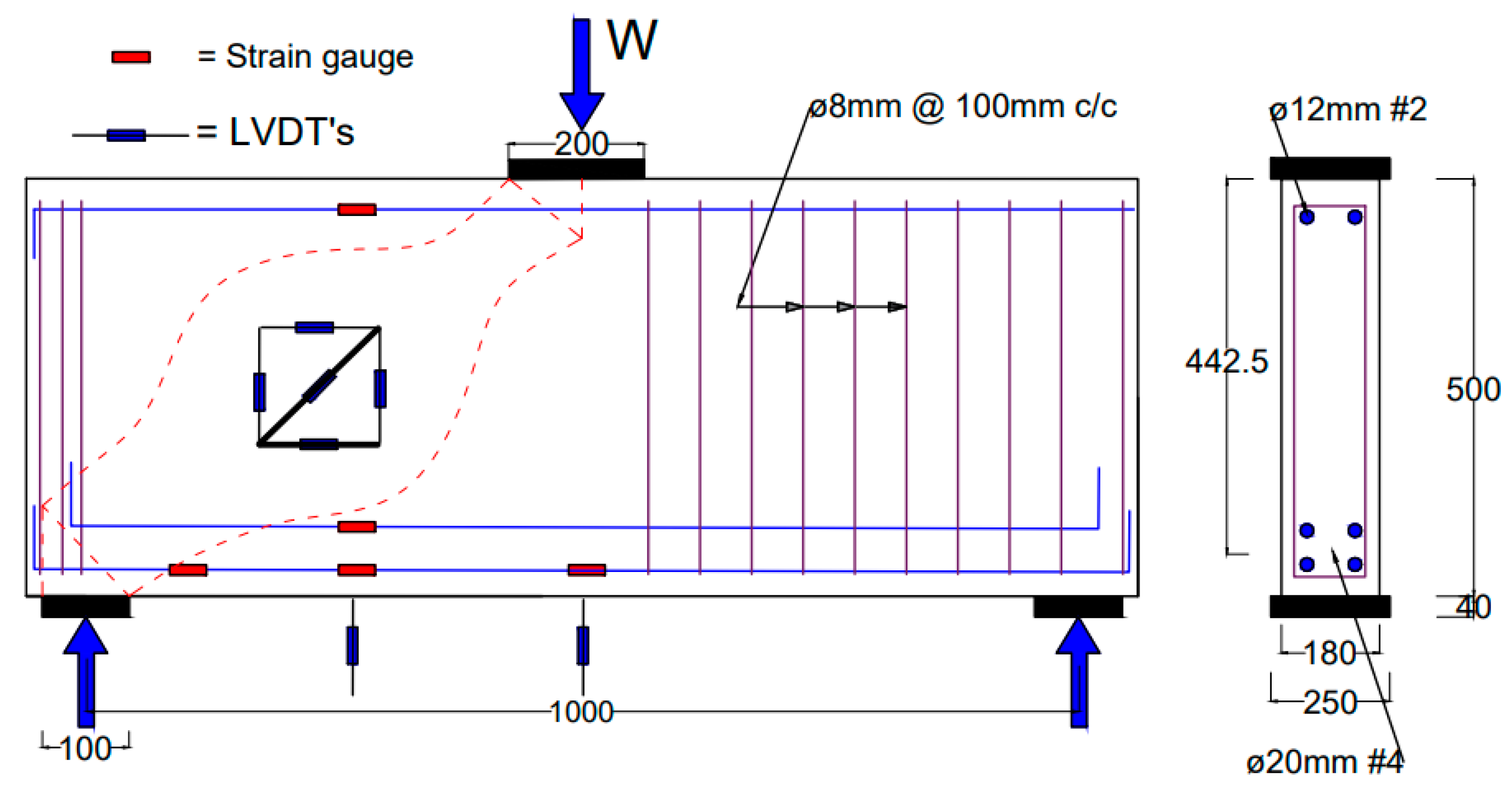
The study comprised testing of five self-compacting reinforced concrete (RC) deep beam specimens with a/h of 1.0 under simply supported support conditions with a central point load as shown in Figure 3. As the size of the beam specimens is near full scale, one beam is tested in each type as has been done by several researchers in the past [44,49,50,51,52]. For each type of mix, six cubes of 150 mm were cast and tested at the same age of beam. The average compressive strength of the cubes is summarized in Table 1, and the same is used in the analysis of beam results. All instrumentation and measurements were mounted on one side of the beam where failure was forced by strengthening the other side with stirrups. The failure zone in the beam is mentioned as a study region in this paper.

3.1. Test Specimen Details

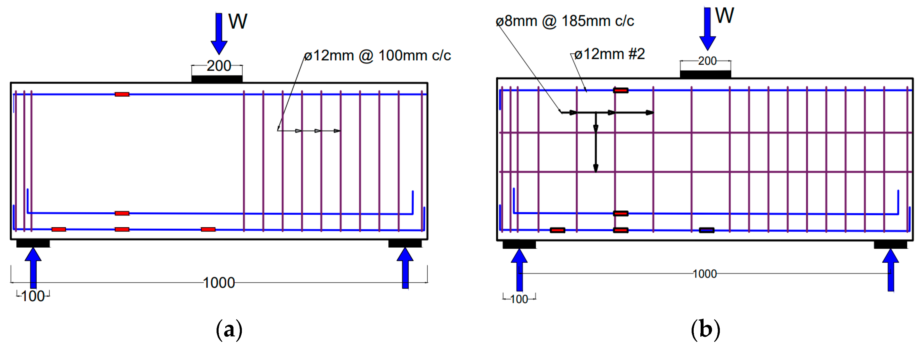
Deep beams with different types of fibers and web reinforcement were cast and tested under concentric load. The test specimens were designed using the Strut and Tie method (STM). The first specimen was made of plain concrete with no web reinforcement. The second, third and fourth specimens had a 0.5% volume fraction of steel fibers (SF), macro-synthetic fibers (MSF), and hybrid fibers (0.25% steel and 0.25% MSF), respectively, with no web reinforcement. The fifth one had standard minimum web reinforcement (0.3%) in the orthogonal directions as per AASHTO LRFD. The reinforcement layout is schematically shown in Figure 4 for plain concrete, web reinforcement, and fiber-reinforced specimens. Table 2 provides the test matrix. The deep beams are designated using the notation DB-X-Y, where ‘X’ is the type of fiber (F—no fiber, SF—steel fiber, MSF—macro synthetic fiber, HB—hybrid fiber) and ‘Y’ is fiber content (50 denotes a 0.5%volume fraction). For the beam with web reinforcement, the notation DB-S-0.3 is used, where S denotes steel and 0.3 denotes the percentage of web reinforcement. The fiber distribution in all FRC beams is considered to be uniform. All beams had a rectangular cross-section of 180 mm in width and 500 mm in depth. The length of the beam was 1300 mm with an effective span of 1000 mm. The beams were reinforced with four numbers of 20 mm diameter bars as longitudinal reinforcement on the tension side and two 12 mm diameter rebar on the compression side. The effective concrete cover to the tension reinforcement was 57.5 mm, rendering an effective depth of d = 442.5 mm. Steel plates of 200 mm wide and 100 mm wide were used at the loading point and support. The non-study region of the deep beam is strengthened by providing the shear reinforcement of 0.5% [53,54,55,56,57] as shown in Figure 4. One side of the beam was reinforced with stirrups to ensure that the failure of the beam occurs in the study region so that detailed instrumentation including DIC could be focused on that region.

3.2. Materials

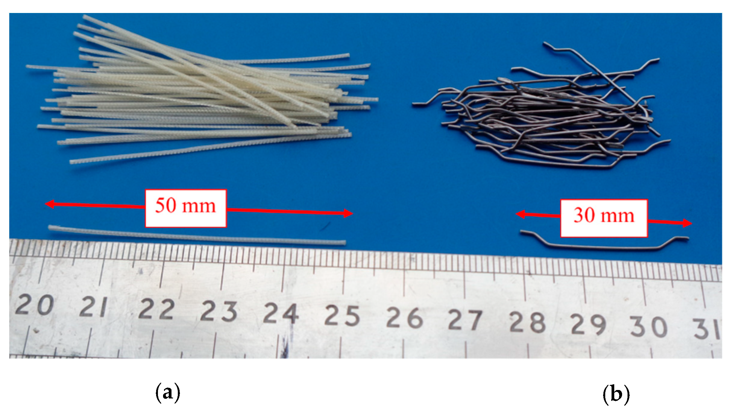
Concrete mix designs were developed for self-compacted concrete based on EFNARC guidelines [58]. For a target mean strength of 45 MPa, the water and powder contents were 215 L/m3 and 500 kg/m3, respectively. Table 3 shows the mix proportions of SCC used in this study. Ordinary Portland cement of grade 43 and Class-F Fly ash is used. The coarse aggregates were crushed gravel with a nominal particle size of 10 mm. Manufactured sand is used as fine aggregate. Polycarboxylate type superplasticizer used as an admixture to obtain the flow of concrete. Hooked-end steel and macro synthetic fibers are used in the study and are shown in Figure 5. Mechanical properties of the used fibers are summarized in Table 4. The SCC mix was thoroughly mixed using a drum mixer. The SCC was placed in the moulds in three lifts. The concrete was placed at one end of the moulds in each lift and allowed to flow along the length under its weight. No vibration was used in the entire casting process. Specimens were finished with light troweling. All the specimens were demoulded after 24 h of casting and water cured for a minimum of 28 days. The details of the compressive strength and density of the cubes for different fiber proportions are shown in Table 1. Thermomechanically treated (TMT) steel rebars of Fe 500 grade of different diameters of 20 mm, 12mm, and 8 mm were used as steel reinforcement.

3.3. Test Setup and Instrumentation

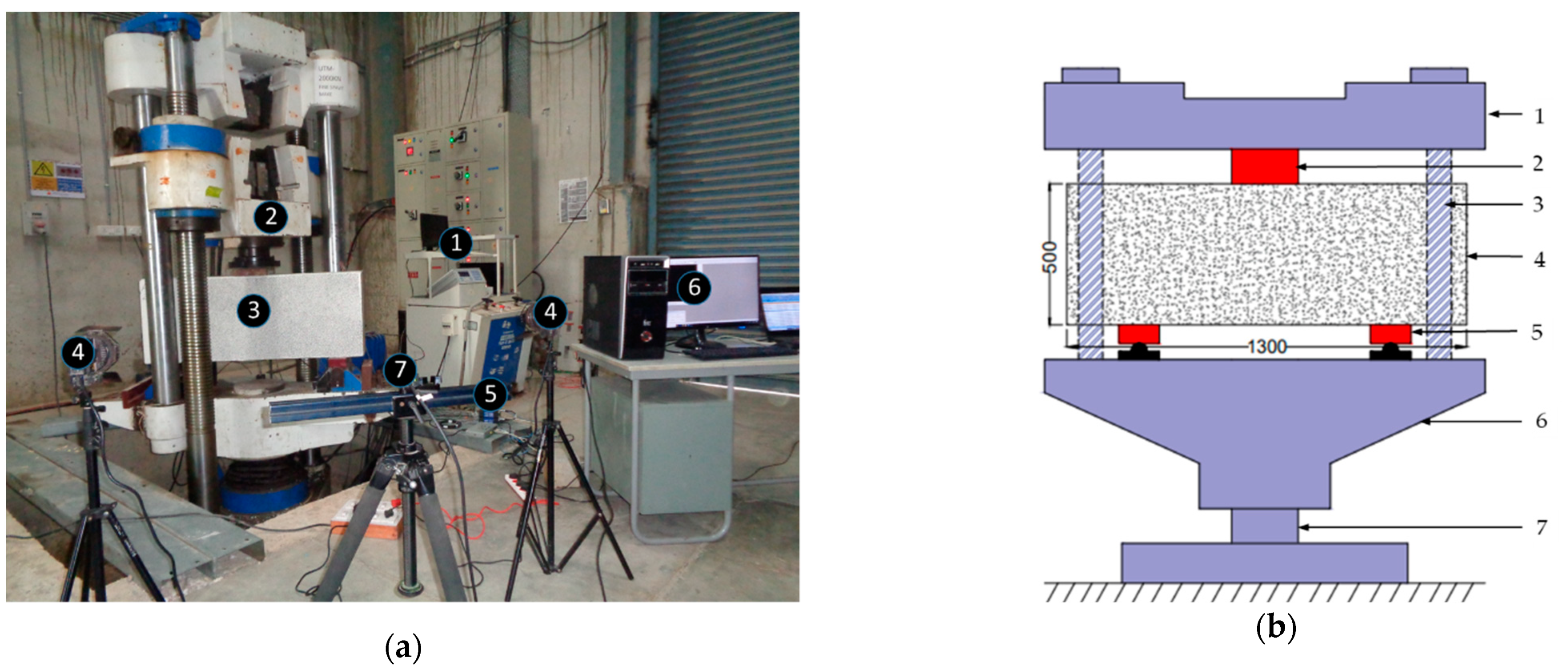
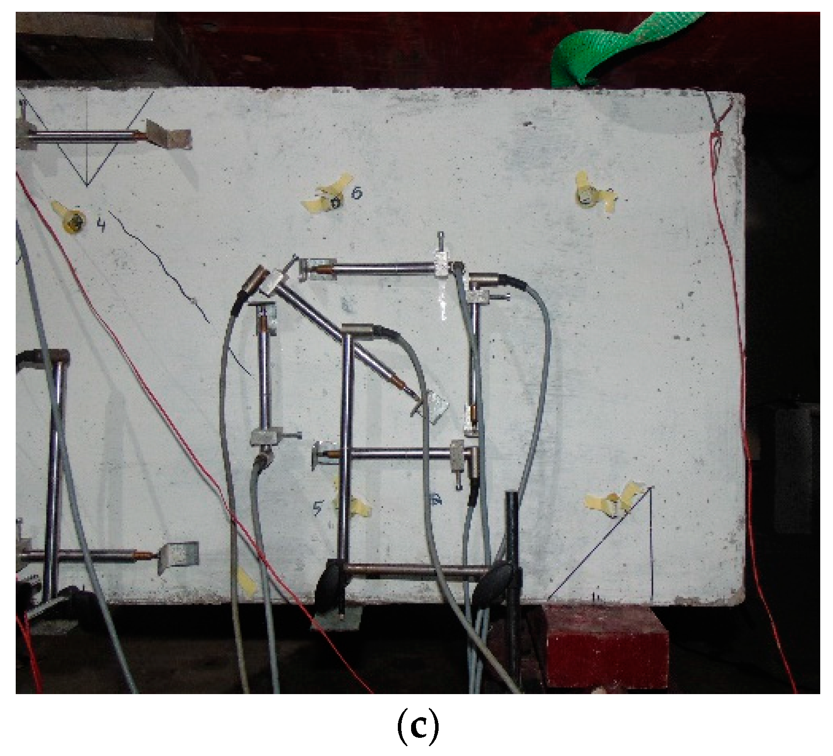
The deep beams were tested in simply supported conditions with a central point load using a 2000 kN universal testing machine (UTM). Figure 6 illustrates the test setup and instrumentation used while testing. Figure 6a presents the overall test setup, Figure 6b includes the details of specimen dimensions, details of UTM and Figure 6c includes the details of LVDT for measuring principal strains in strut region. The displacement rate in UTM was kept at 2 mm/min. Deflections at various locations are measured using linear variable differential transducers (LVDTs) throughout the loading history. A rosette with five LVDTs is arranged to obtain the principal strains in the critical bottle-shaped strut location.

3.4. Digital Image Correlation (DIC)

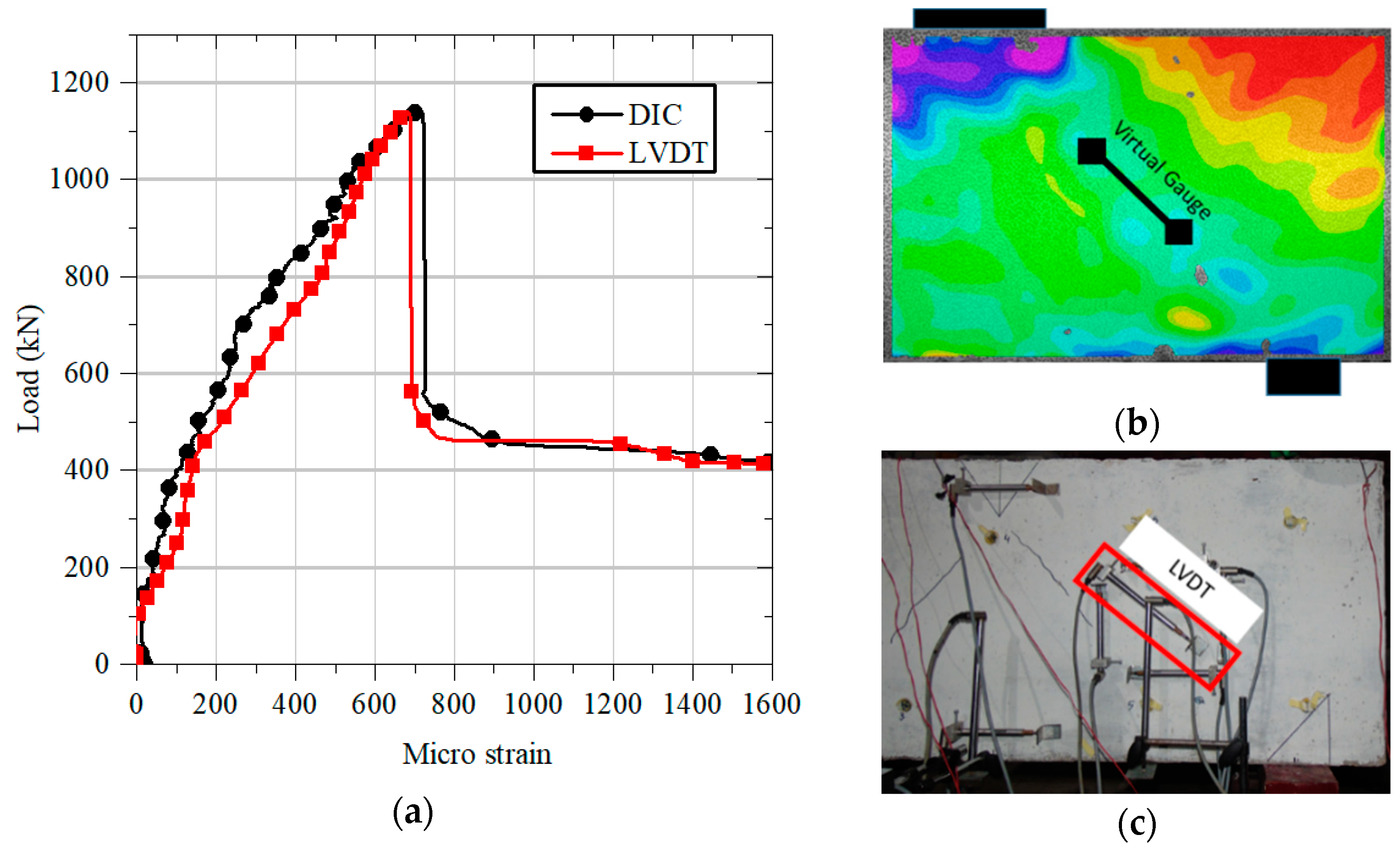
DIC is an optical-based technique used to measure the evolving full-field 2D or 3D coordinates on the surface of the specimen throughout the test. Displacements, strains, strain rates, etc. can be calculated from the measured coordinate fields. The procedure involved in using the DIC technique is (i) specimen preparation and capturing of images, (ii) analysis of Images using VIC-2D (image correlation), (iii) post-processing (extracting the required data from the analyzed images). All the specimen’s surface were painted by using acrylic-based white paint and speckling is performed manually using a marker pen. Care was taken to ensure the equal intensity of light on the test zone to capture high-resolution images with quality. Before application of the load, a calibration (with scale) and reference images (undeformed shape) were captured for analysis purposes. To validate the DIC results, the strains measured using LVDT and DIC at the beam center and along the strut axis are plotted for the DB-SF-50 beam and shown in Figure 7a for the same gauge length, and they are in good agreement. The locations of strain measurements using DIC and LVDT are shown in Figure 7b, Figure 7c, respectively.

4. Results and Discussion

All the tested specimens failed by forming a diagonal crack joining the inner edge of the support plate and the outer edge of the loading plate, which is typically mentioned in this paper as a critical crack. The load-carrying capacity of the tested deep beams depends on the propagation of critical crack initiated near the support plate and extends to the loading plate. The performance of the tested deep beam specimens was evaluated based on the load-deflection response, cracking load, strain measurements, crack patterns, and failure modes. As the DIC technique was employed in the study region of the beam with five images per second, the onset of the first crack and its corresponding load were observed by visible observation.

4.1. Load-Deflection Behavior

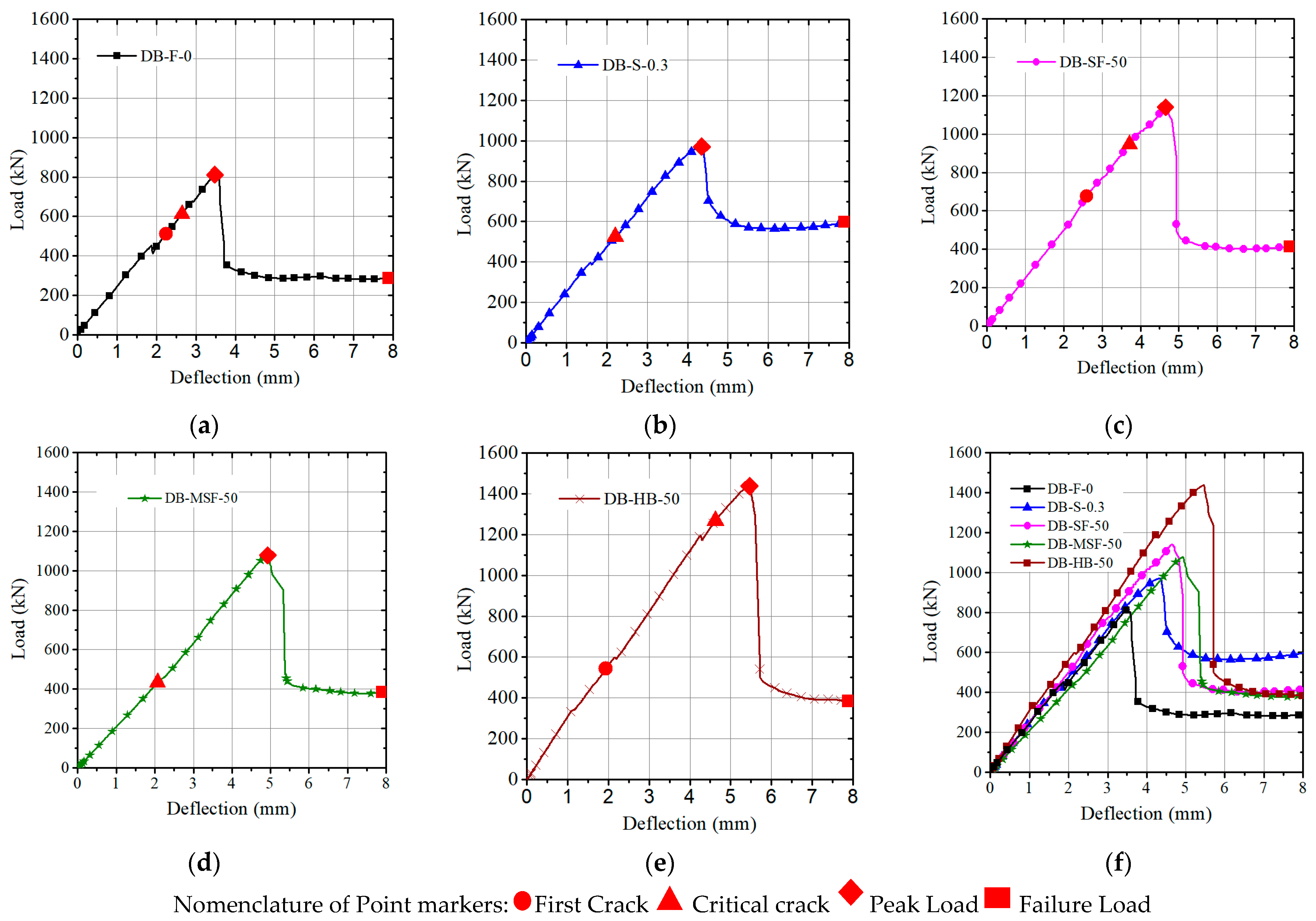
In the UTM used for testing the deep beams, the loading point was fixed, and the supports were designed to move upwards at the specified loading rate. Therefore, the stroke value given by the UTM is an average displacement of supports to the loading point, and that is considered in plotting the load-deflection response of the beam. Even though half of the beam is strengthened by providing steel stirrups to force the failure on one side, the occurrence of the first crack in the beam can be on any side as the reinforcement will be active only after the formation of cracks. Therefore, any first drop in the load-deformation curve need not be due to crack formation in the study region. The load-deflection response of all the specimens is shown in Figure 8 in which the load is normalized by dividing with fcm bd to negate the influence of concrete compressive strength variation. Individual load-deflection responses are shown in Figure 9, along with points to indicate first crack, peak, and failure loads. Failure load is taken at a displacement of 8 mm for comparison and energy calculation as there is no change in load resistance after that.
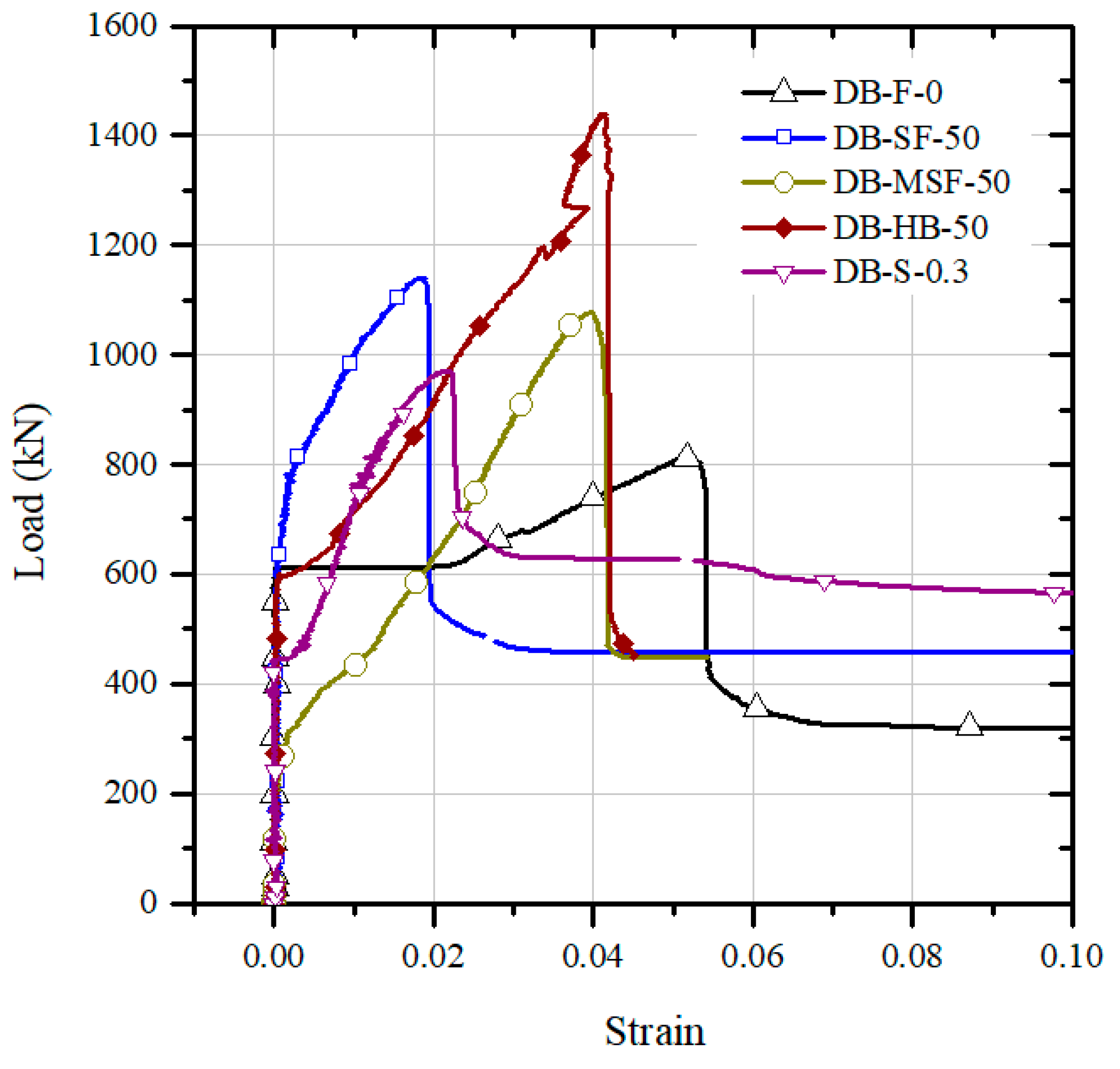
The initial stiffness of the control beam DB-F-0 and the beam with minimum web reinforcement DB-S-0.3 is similar. However, the specimens DB-SF-50 and DB-HB-50 with steel and hybrid fibers exhibited slightly higher stiffness. DB-MSF-50 reinforced with macro synthetic fibers showed comparatively lower stiffness. After the first diagonal crack, a slight drop in the load resistance and a change in the stiffness were observed in the load–displacement curve. The control specimen DB-F-0 exhibited a load decay at the onset of shear cracking followed by a significant change in slope of the deflection response compared to the specimens with fibers or web reinforcement. After the formation of the diagonal crack, all the specimens continued to resist the applied load until the critical diagonal crack extended from the inner edges of the support plate at the bottom to the outer edge of the loading plate at the top. A detailed description of the behavior of each specimen is given below.

4.1.1. DB-F-0

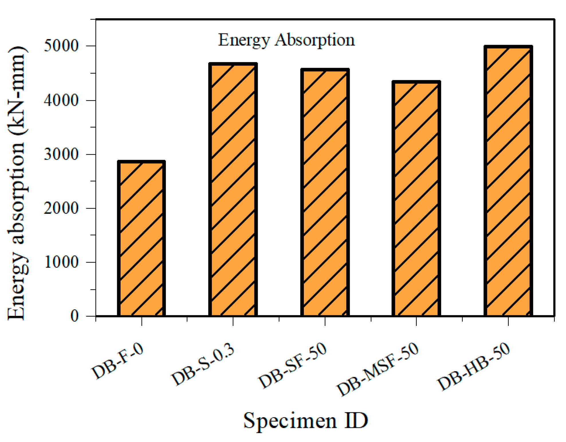
The load-deflection response of the control beam (DB-F-0) with plain concrete in the critical strut region is shown in Figure 9a. The first diagonal crack occurred at a load of 511.5 kN with a corresponding deflection of 2.24 mm. At this load, the transverse tension in the bottle-shaped strut region exceeded the tensile strength of concrete. Even after the formation of diagonal cracking, the load resistance increased up to 812.5 kN due to shear resistance from uncracked concrete, dowel action of tie rebars, and aggregate interlock at the cracked interface until the critical crack extended to the full depth of the beam. The first diagonal crack is at around 63% of its ultimate capacity, indicating only 37% reserve capacity between the first crack and ultimate load. After reaching the peak load, the specimen failed due to widening and complete separation along the diagonal crack, which is indicated by a sudden drop in the load resistance. Residual load resistance of 260 kN after the load drop is due to the dowel action of the tensile reinforcement in the beam. The beam failure can be classified as a diagonal splitting in the strut region. The failure mode after peak load is very sudden, and energy absorption of 2863.8 kN-mm is observed.

4.1.2. DB-S-0.3

The DB-S-0.3 specimen was reinforced within the test zone with 0.3% web reinforcement in both horizontal and vertical directions as per AASHTO-LRFD recommendations. The load-deflection response of DB-S-0.3 is shown in Figure 9b. The first diagonal crack occurred at a load of 524.7 kN, which is not significantly higher than the plain concrete beam (DB-F-0). It is attributed to the fact that the reinforcement is effective only after the first cracking. After the onset of diagonal cracking, web reinforcement, uncracked concrete portion, and aggregate interlock continued to resist the load. Due to the improved resistance to crack arrest by the web reinforcement, the beam could reach an ultimate load of 970.8 kN at a deflection of 4.35 mm, which is 25% higher than DB-F-0. A higher residual load of 575 kN after the load drop is observed in this specimen due to the yielding of web reinforcement and from the dowel action of tensile reinforcement. The specimen DB-S-0.3 finally failed in a diagonal splitting mode due to the rupture of the web reinforcement crossing the critical shear crack.

4.1.3. DB-SF-50

The specimen DB-SF-50 contains 0.5% volume fraction of steel fibers. The load-deflection response is shown in Figure 9c. DB-SF-50 had a higher first diagonal cracking load of 677.7 kN, which is attributed to an increase in the tensile strength of concrete due to the addition of steel fibers. Even after the formation of critical crack, steel fibers were quite effective in controlling the crack propagation to the full depth of the beam which enabled the beam to reach the higher ultimate load-carrying capacity of 1140 kN, which is 18% higher than DB-S-0.3. Though the total volume of reinforcement is almost the same between 0.5% steel fiber and 0.3% conventional reinforcement in the web in the orthogonal direction, the resistance offered by the steel reinforcement is concentrated at a few locations, whereas fibers resist tension at every location across the crack. After the peak, the load drop is not sudden as in the case of DB-F-0, as the steel fibers did not allow the critical crack to widen at a faster rate. This leads to a gradual loss of aggregate interlock resistance. Finally, the specimen failed due to the rupture or pull out of steel fibers at the crack interface. The residual capacity of the beam was maintained at 400 kN, due to the dowel action of longitudinal tie reinforcement. Higher residual load resistance compared to DB-F-0 is attributed to the improved bond strength due to fiber addition. The final failure mode of the DB-SF-50 beam is observed as diagonal splitting along the critical shear crack.

4.1.4. DB-MSF-50

The specimen DB-MSF-50 contains 0.5% volume fraction of macro synthetic fibers (MSF) in concrete. The load-deflection behavior is shown in Figure 9d. No significant improvement in the first diagonal crack is observed due to MSF addition compared to the plain concrete beam (DB-F-0) because the addition of MSF to the concrete will not improve the maximum tensile strength of concrete [59]. Due to the low stiffness of macro synthetic fibers, they could not help in the effective arresting of tensile stresses at small crack widths [29,60]. After the onset of critical crack, synthetic fibers become more effective and control the crack propagation, leading to a higher load-carrying capacity of 1078.5 kN, which is 13% higher than DB-S-0.3. Reserve capacity of 60% of the ultimate load is observed between the first crack and peak load. After the peak, reduction in the load is accompanied by increased deflection due to the excellent bridging action of synthetic fibers at large crack widths, unlike DB-S-0.3 and DB-SF-50. The residual capacity of the beam is observed to be the same as that of the DB-SF-50 beam due to improved bond strength compared to plain concrete. The beam finally failed due to the rupture of fibers at the crack interface in diagonal splitting mode.

4.1.5. DB-HB-50

The specimen DB-HB-50 contains a combination of steel and synthetic fibers in 0.25% volume fraction. The load-deflection behavior is shown in Figure 9e. First cracking is observed at a load level of 544.2 kN, which lies between DB-SF-50 and DB-MSF-50. Hybridization of steel and synthetic fibers results in higher ultimate load carrying capacity and slows down the load resistance drop after the peak. Improved performance of DB-HB-50 is due to the synergy of both steel and synthetic fibers in different ranges of crack widths.
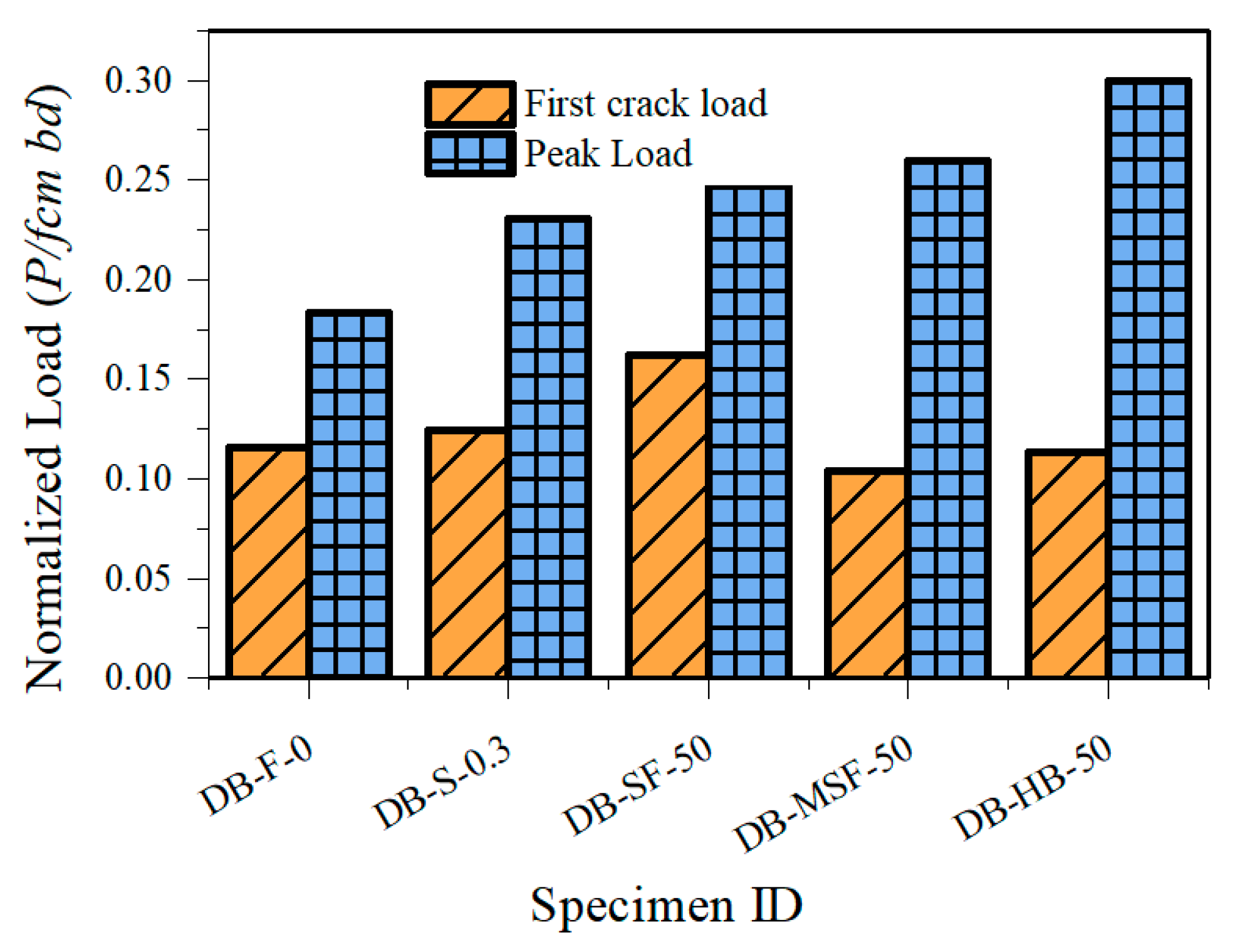
For all the tested specimens, first cracking load, peak load, deflections at peak, and failure mode are summarized in Table 5. Due to variations in the compressive strength of concrete of different specimens, the load-carrying capacities at cracking and ultimate were normalized by dividing the load with fcm bd and plotted for comparison in Figure 10. Similarly, the energy absorption capacity of all the deep beams was calculated by the area under the load-deflection curve to compare the pseudo ductility of the different FRC beams and plotted in Figure 11.

4.2. Strains in the Longitudinal Reinforcement

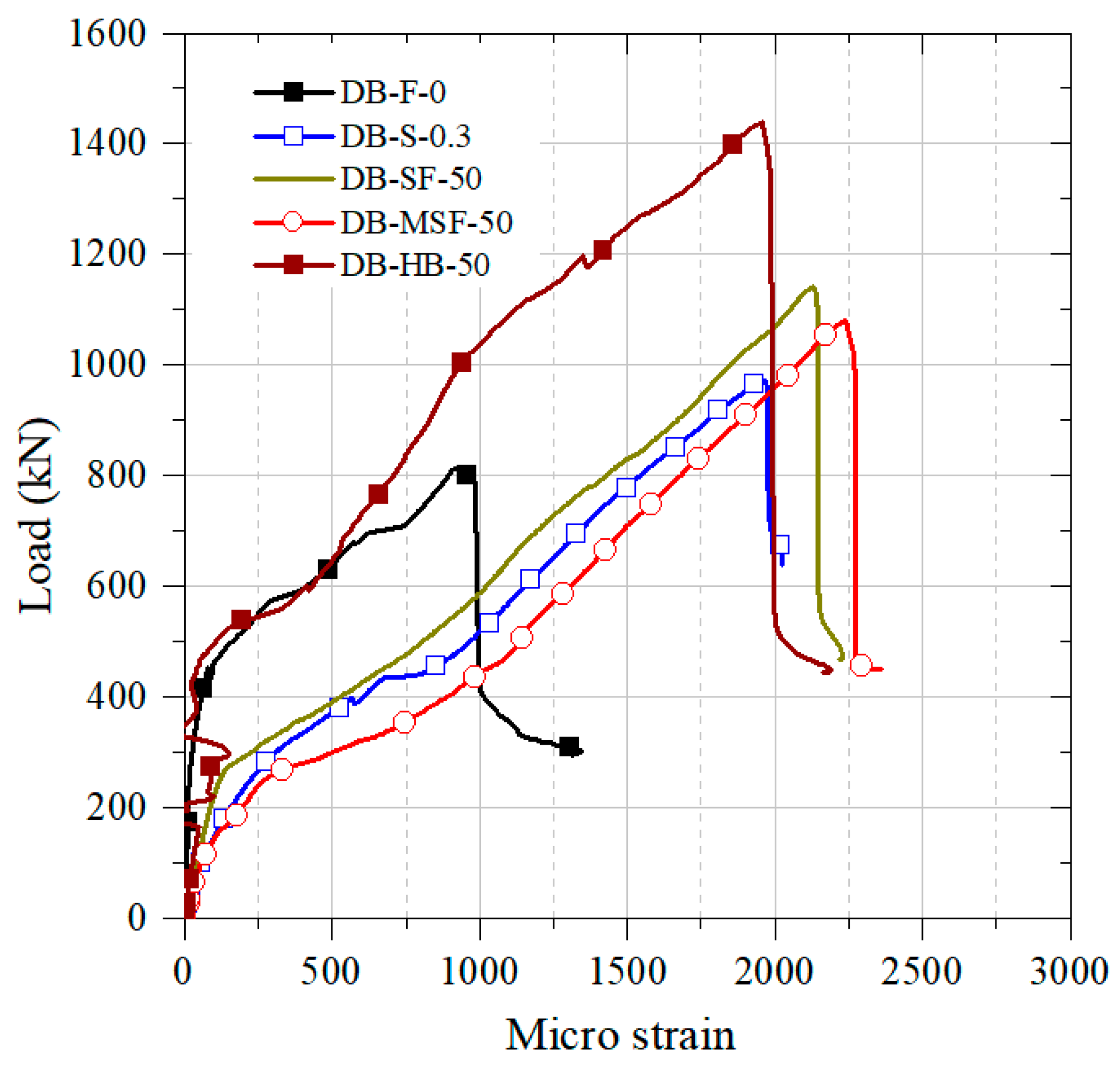
Strains in the longitudinal tensile reinforcement in the deep beams are measured using strain gauges and their variation is plotted with the load in Figure 12. It is observed that maximum strain in the rebar is not yielded at the peak load-carrying capacity for all the specimens as the specimens fail in shear due to transverse tension. For specimen DB-F-0 with only plain concrete in the strut region, the strain in the rebar is low compared to the specimens with web reinforcement or fibers. This may be because of absence of any resistance to the transverse strain in the strut region. The beam failed at a low load, leading to less tensile force in the longitudinal reinforcement and thereby low strain at the peak load.

4.3. Global Cracking Behavior of the Tested Beams

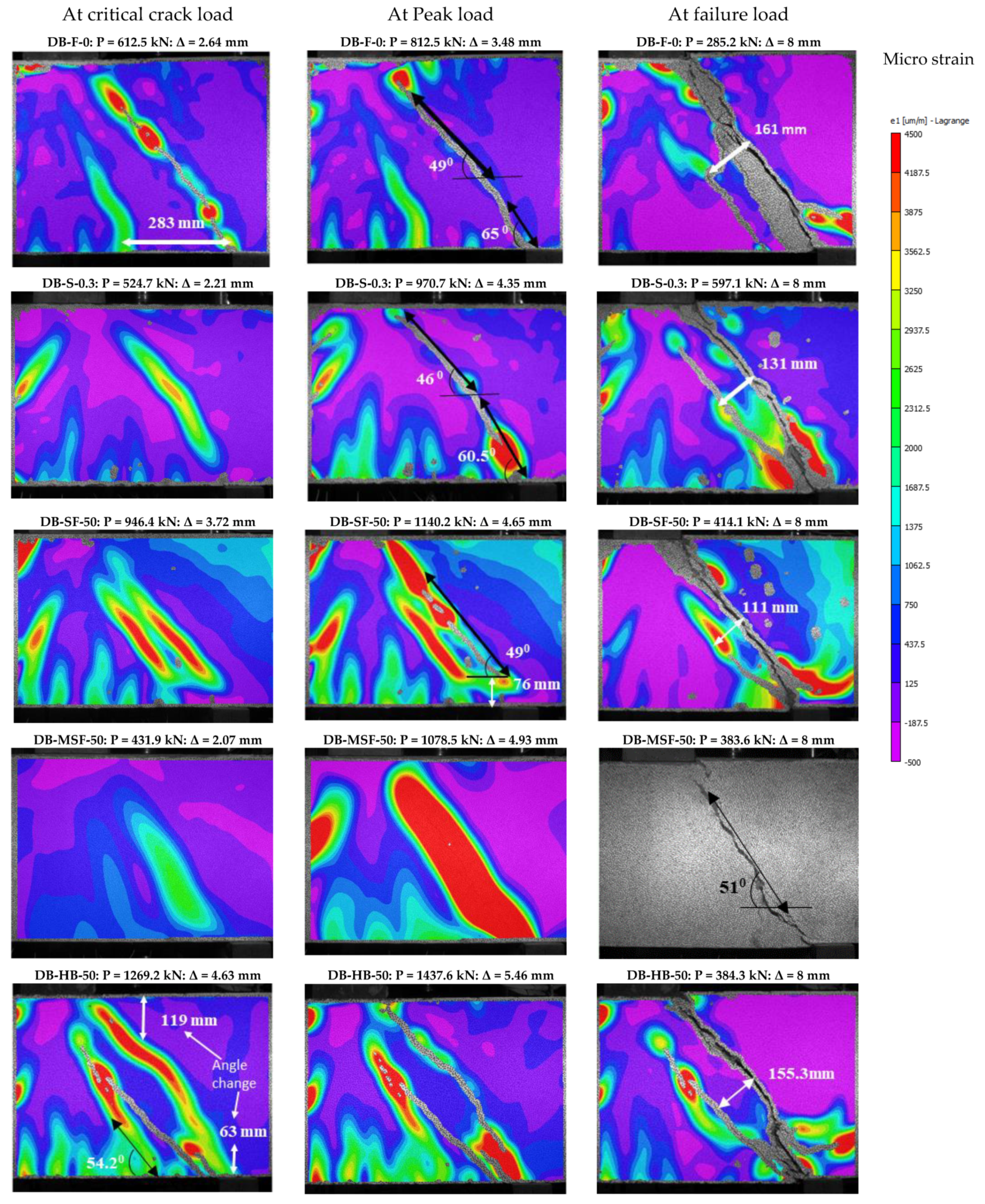
As mentioned in Section 4, the final failure of all the tested specimens is along the critical crack. For specimens, DB-MSF-50 and DB-S-0.3, only one diagonal crack is (critical crack) formed up to the peak load. For the remaining specimens, another diagonal crack is formed parallel and before the critical crack referred to in this study as a non-critical crack. The formation of non-critical cracks in some specimens may be due to any weak link in concrete in the strut region due to its heterogeneous nature. Occurrence of non-critical crack delays the critical crack. A non-critical crack tends to close or remains at the same width and length as the critical crack starts progressing. The load resistance continues to increase until the critical crack extends to the full depth of the beam. The load resistance drops after the complete separation of the specimen along the critical crack. Longitudinal tension reinforcement continues to resist some load even after the separation of the concrete portion, which can be observed in the Load-deformation response in Figure 8 and Figure 9. The presence of web reinforcement did not alter the instance of the first crack but effectively controlled the crack widening and propagation. The presence of discrete fibers was also found to be effective as conventional web reinforcement in arresting the critical crack through bridging action and helps to achieve higher load-carrying capacity. The cracking process at different load levels in the study area is shown in Figure 13, which is a variation of principal tensile strain measured using the DIC technique. The final failure of the specimens is shown in Figure 14.

4.4. Transverse Strain Variation at First Crack

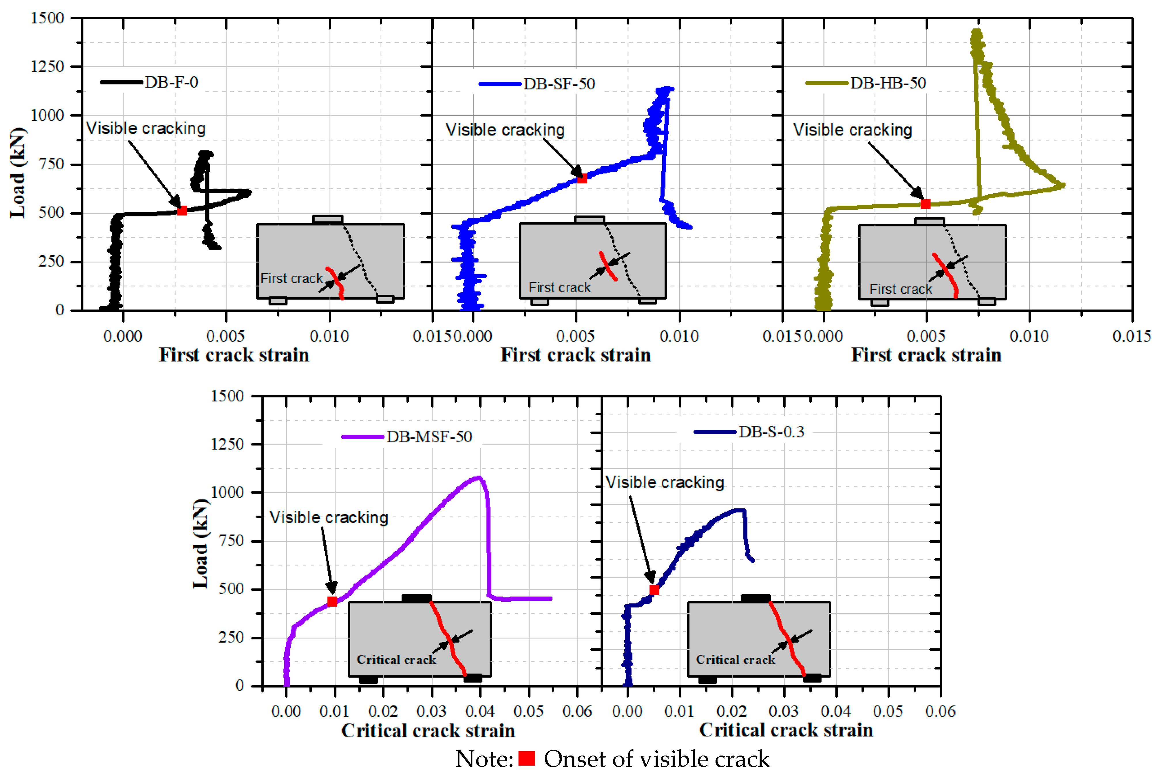
In deep beams at a low shear span to depth ratio (a/h), crack occurrence and propagation are faster. Strain in concrete at the instance of first crack load, peak load, and its variation with an increase in load gives good insight into the cracking process and failure of the beam. The use of DIC allowed observation of the strains on the concrete surface, crack occurrence, crack propagation very accurately with 0.2 s time interval. To find the strain normal to crack, a virtual extensometer is placed normally in relation to the crack and extracted the strain value throughout the loading history for every 0.2 s. As mentioned in Section 4.2, the first crack could be critical or non-critical. Transverse strain across the first crack is plotted against the load and shown in Figure 15. A point is shown in the graph, which indicates the instance of a visible crack on the specimen.
In specimens DB-F-0, DB-SF-50, and DB-HB-50, transverse strain is plotted for the non-critical crack, and for specimens DB-MSF-50 and DB-S-0.3, transverse strain is plotted for the critical crack.
The plain concrete was not able to offer any resistance after the onset of cracking. Hence, a sudden strain increment can be observed at constant load in the specimens DB-F-0 and DB-S-0.3. In DB-S-0.3, the web reinforcement present in the strut region becomes active after the first crack, and the strain has slowly increased until the peak load. In the specimens DB-SF-50 and DB-MSF 50, the transverse strain increased gradually, unlike in the case of plain concrete. This may be due to the resistance of fibers in concrete against abrupt energy release in cracking. The strain at first cracking in DB-F-0 is observed as 0.003. In the remaining specimens except for DB-MSF-50, the strain at cracking is around 0.005. The specimen DB-MSF-50 with synthetic fibers showed an apparent tensile strain of 0.01 at first cracking, almost double that of the specimens with steel fiber, hybrid fiber, and steel reinforcement. This shows that synthetic fibers in concrete make the concrete soft and cause higher surface strains compared to steel fibers.

4.5. Stain Variation in Critical Crack

Strain across the critical crack is measured in all the specimens using the virtual extensometer using DIC and plotted against the load and shown in Figure 16. The sudden increase in the strain at the onset of critical crack and strain of 0.0055 at the peak load is observed in DB-F-0. This increase was due to the larger widening of the critical crack in plain concrete due to a lack of resistance for the tensile strain. In DB-S-0.3, web reinforcement present in the specimen resists the crack widening and leads to a lower strain of 0.0025 at peak load, almost half of that observed in DB-F-0. The addition of 0.5% steel fibers also shows similar behavior as that of web reinforcement in terms of strain increment, strain at the peak load, and observed higher peak load due to the distribution of resistance across the crack length due to the fiber. The addition of synthetic fibers to the concrete showed a slow increment in the strain and larger strain values than steel fibers. This may be due to the effectiveness of synthetic fibers in bridging the crack at larger crack widths. Hybridization of steel and synthetic fibers showed the combined improvement effect of individual fibers, resulting in large strains at the peak and higher peak load resistance.

5. Summary and Conclusions

The provision of web reinforcement or discrete fibers is essential in deep beams to improve their performance. The addition of fibers resulted in increased load carrying capacity, limited crack widths, higher reserve load after the first crack, and reduced brittleness in failure mode. The possibility of replacing web shear reinforcement with discrete fibers was evaluated by conducting experiments on RC deep beams. From the experimental results, the following conclusions can be drawn:
  • The RC deep beams tested at an a/h ratio equal to one, primarily failed in the diagonal splitting mode in the bottle-shaped strut region by forming a diagonal crack between the inner edge of the support and the loading point. In plain concrete deep beams, the critical diagonal crack progressed to the entire beam depth at a faster rate leading to brittle failure. No resistance to the transverse tension led to low reserve capacity between the first crack and ultimate load.
  • The addition of minimum web reinforcement in the deep beam effectively controlled the progress of the critical crack. Provision of web reinforcement led to higher reserve capacity after the first crack and higher peak load-carrying capacity. However, no change in the first crack load was observed in beams with web reinforcement compared to the plain concrete specimen.
  • The addition of discrete steel fibers or macro synthetic fibers serves the purpose of arresting widening and propagation of the critical crack like conventional web reinforcement. Discrete fibers were more effective than conventional web reinforcement as the former can arrest the crack at every location, unlike web reinforcement.
  • The addition of steel fibers in the concrete contributed to a higher first crack load in the deep beams, increasing the concrete tensile strength by arresting the micro cracks. Macro synthetic fibers were effective only at larger crack widths and could not improve the first crack load.
  • The energy absorption capacity of the deep beams with 0.5% discrete fibers was on par with 0.3% conventional web reinforcement in both directions.
  • Hybridization of steel and macro synthetic fibers resulted in higher ultimate load-carrying capacity compared to specimens reinforced with only steel or macro synthetic fibers. Hybridization also resulted in gradual load drop due to the effectiveness of synthetic fibers at larger crack widths.
  • Limited test results from this study show that minimum web shear reinforcement of 0.3% in the diagonal strut region of deep beams can be replaced with 0.5% of either macro steel or macro synthetic or hybrid fibers. Fiber addition of 0.5% can provide similar or higher ultimate load carrying capacity, reserve capacity, and energy absorption.
  • The provision of web reinforcement or discrete fibers in concrete did not change the final failure mode of deep beams with a low a/d ratio. All the specimens failed in diagonal splitting mode along the critical crack.

Author Contributions

M.S.V.S., C.L., S.S.P. and A.S. designed the test matrix. M.S.V.S. and C.L. performed the experiments and wrote the paper. S.S.P. and A.S. reviewed the paper. All authors have read and agreed to the published version of the manuscript.

Funding

“IMPRINT Scheme-Order # IMP/2018/000846” by the Ministry of Human Resource Development, Department of Science and Technology, and Prime Minister Research Fellowship-India Project Number # CE19RESCH11007-PMRF.

Institutional Review Board Statement

Not applicable.

Informed Consent Statement

Not applicable.

Data Availability Statement

The data presented in this study are available within the manuscript.

Conflicts of Interest

The authors declare no conflict of interest.

References

  1. Kani, G. How safe are our large reinforced concrete beams? ACI J. Proc. 1967, 64, 128–141. [Google Scholar] [CrossRef]
  2. GNJ, K. Basic facts concerning shear failure. ACI J. Proc. 1966, 63, 675–692. [Google Scholar] [CrossRef]
  3. Schlaich, J.; Schaefer, K.; Jennewein, M. Toward a consistent design of structural concrete. PCI J. 1987, 32, 74–150. [Google Scholar] [CrossRef]
  4. Ismail, K.S.; Guadagnini, M.; Pilakoutas, K. Strut-and-Tie modeling of reinforced concrete deep beams. J. Struct. Eng. 2018, 144, 04017216. [Google Scholar] [CrossRef]
  5. Mihaylov, B.I.; Bentz, E.C.; Collins, M.P. Two-parameter kinematic theory for shear behavior of Deep beams. ACI Struct. J. 2013, 110, 447–456. [Google Scholar]
  6. American Concrete Institute. Building Code Requirements for Structural Concrete Available for Public Review (ACI 318-19); ACI: Indianapolis, IN, USA, 2019; ISBN 9781641950565. [Google Scholar]
  7. Canadian Standard Association. CSA-A23.3-04: Design of Concrete Structures; Canadian Standard Association: Ottawa, ON, Canada, 2007; pp. 122–190. [Google Scholar] [CrossRef]
  8. Standards Australia. AS 5100.5: Bridge Design-Concrete; Standards Australia International Ltd.: Sydney, Australia, 2017. [Google Scholar]
  9. European Committee for Standardization. Eurocode 2: Design of Concrete Structures, Part 1-1: General Rules and Rules for Buildings; The European Union: Brussels, Belgium, 2011; Volume 54, ISBN 9781479918058. [Google Scholar]
  10. American Association of State Highway and Transportation Officials (AASHTO). LRFD Bridge Design Specifications; American Association of State Highway and Transportation Officials (AASHTO): Washington, DC, USA, 2012. [Google Scholar]
  11. Michael, D.B.; Sankovich, C.L.; Bayrak, O.; James, O.J. Behavior and efficiency of bottle-shaped struts. ACI Struct. J. 2006, 103, 348–355. [Google Scholar]
  12. Sahoo, D.K.; Singh, B.; Bhargava, P. An appraisal of the ACI strut efficiency factors. Mag. Concr. Res. 2009, 61, 445–456. [Google Scholar] [CrossRef]
  13. Birrcher, D.B.; Tuchscherer, R.G.; Huizinga, M.; Bayrak, O. Minimum web reinforcement in deep beams. ACI Struct. J. 2013, 110, 297–306. [Google Scholar]
  14. Brown, M.D.; Bayrak, O. Minimum transverse reinforcement for bottle-shaped struts. ACI Struct. J. 2007, 104, 642–645. [Google Scholar]
  15. Lakavath, C.; Bhosale, A.; Prakash, S.S. Experimental investigation on crack-arresting mechanism of steel fibre-reinforced concrete prism specimens using DIC and AE techniques. In Lecture Notes in Civil Engineering; Subramaniam, K.V.L., Mohd, A.K., Eds.; Springer: Singapore, 2020; Volume 74, pp. 51–65. ISBN 9789811381805. [Google Scholar]
  16. Bhosale, A.; Rasheed, M.A.; Prakash, S.S.; Raju, G. A study on the efficiency of steel vs. synthetic vs. hybrid fibers on fracture behavior of concrete in flexure using acoustic emission. Constr. Build. Mater. 2019, 199, 256–268. [Google Scholar] [CrossRef]
  17. Rasheed, M.A.; Prakash, S.S. Behavior of hybrid-synthetic fiber reinforced cellular lightweight concrete under uniaxial tension—Experimental and analytical studies. Constr. Build. Mater. 2018, 162, 857–870. [Google Scholar] [CrossRef]
  18. Chiranjeevi Reddy, K.; Subramaniam, K.V.L. Experimental investigation of crack propagation and post-cracking behaviour in macrosynthetic fibre reinforced concrete. Mag. Concr. Res. 2017, 69, 467–478. [Google Scholar] [CrossRef]
  19. Gali, S.; Subramaniam, K.V.L. Evaluation of crack propagation and post-cracking hinge-type behavior in the flexural response of steel fiber reinforced concrete. Int. J. Concr. Struct. Mater. 2017, 11, 365–375. [Google Scholar] [CrossRef] [Green Version]
  20. Amin, A.; Foster, S.J. Shear strength of steel fibre reinforced concrete beams with stirrups. Eng. Struct. 2016, 111, 323–332. [Google Scholar] [CrossRef]
  21. Amin, A.; Gilbert, R.I. Steel fiber-reinforced concrete beams—Part I: Material characterization and in-service behavior. ACI Struct. J. 2019, 116, 101–111. [Google Scholar] [CrossRef]
  22. Cavagnis, F.; Fernández Ruiz, M.; Muttoni, A. Shear failures in reinforced concrete members without transverse reinforcement: An analysis of the critical shear crack development on the basis of test results. Eng. Struct. 2015, 103, 157–173. [Google Scholar] [CrossRef] [Green Version]
  23. Liu, J.; Guner, S.; Mihaylov, B.I. Mixed-type modeling of structures with slender and deep beam elements. ACI Struct. J. 2019, 116, 253–264. [Google Scholar] [CrossRef]
  24. Kytinou, V.K.; Chalioris, C.E.; Karayannis, C.G.; Elenas, A. Effect of steel fibers on the hysteretic performance of concrete beams with steel reinforcement-tests and analysis. Materials 2020, 13, 2923. [Google Scholar] [CrossRef] [PubMed]
  25. Kazemi, M.T.; Fazileh, F.; Ebrahiminezhad, M.A. Cohesive crack model and fracture energy of steel-fiber-reinforced-concrete notched cylindrical specimens. J. Mater. Civ. Eng. 2007, 19, 884–890. [Google Scholar] [CrossRef]
  26. Biolzi, L.; Cattaneo, S. Response of steel fiber reinforced high strength concrete beams: Experiments and code predictions. Cem. Concr. Compos. 2017, 77, 1–13. [Google Scholar] [CrossRef]
  27. Wille, K.; Tue, N.V.; Parra-Montesinos, G.J. Fiber distribution and orientation in UHP-FRC beams and their effect on backward analysis. Mater. Struct. Constr. 2014, 47, 1825–1838. [Google Scholar] [CrossRef]
  28. Cucchiara, C.; La Mendola, L.; Papia, M. Effectiveness of stirrups and steel fibres as shear reinforcement. Cem. Concr. Compos. 2004, 26, 777–786. [Google Scholar] [CrossRef]
  29. Lakavath, C.; Suriya Prakash, S.; Dirar, S. Experimental and numerical studies on shear behaviour of macro-synthetic fibre reinforced prestressed concrete beams. Constr. Build. Mater. 2021, 291, 123313. [Google Scholar] [CrossRef]
  30. Torres, J.A.; Lantsoght, E.O.L. Influence of fiber content on shear capacity of steel fiber-reinforced concrete beams. Fibers 2019, 7, 102. [Google Scholar] [CrossRef] [Green Version]
  31. Joshi, S.S.; Thammishetti, N.; Prakash, S.S. Efficiency of steel and macro-synthetic structural fibers on the flexure-shear behaviour of prestressed concrete beams. Eng. Struct. 2018, 171, 47–55. [Google Scholar] [CrossRef]
  32. Buratti, N.; Mazzotti, C.; Savoia, M. Post-cracking behaviour of steel and macro-synthetic fibre-reinforced concretes. Constr. Build. Mater. 2011, 25, 2713–2722. [Google Scholar] [CrossRef]
  33. Lee, S.J.; Won, J.P. Flexural behavior of precast reinforced concrete composite members reinforced with structural nano-synthetic and steel fibers. Compos. Struct. 2014, 118, 571–579. [Google Scholar] [CrossRef]
  34. Rasheed, M.A.; Prakash, S.S. Mechanical behavior of sustainable hybrid-synthetic fiber reinforced cellular light weight concrete for structural applications of masonry. Constr. Build. Mater. 2015, 98, 631–640. [Google Scholar] [CrossRef]
  35. Sahoo, S.; Lakavath, C.; Prakash, S.S. Experimental and analytical studies on fracture behaviour of fibre-reinforced structural lightweight aggregate concrete. J. Mater. Civ. Eng. 2021, 33, 04021074. [Google Scholar] [CrossRef]
  36. Sahoo, S.; Selvaraju, A.K.; Suriya Prakash, S. Mechanical characterization of structural lightweight aggregate concrete made with sintered fly ash aggregates and synthetic fibres. Cem. Concr. Compos. 2020, 113, 103712. [Google Scholar] [CrossRef]
  37. Conforti, A.; Minelli, F.; Tinini, A.; Plizzari, G.A. Influence of polypropylene fibre reinforcement and width-to-effective depth ratio in wide-shallow beams. Eng. Struct. 2015, 88, 12–21. [Google Scholar] [CrossRef]
  38. Soutsos, M.N.; Le, T.T.; Lampropoulos, A.P. Flexural performance of fibre reinforced concrete made with steel and synthetic fibres. Constr. Build. Mater. 2012, 36, 704–710. [Google Scholar] [CrossRef]
  39. Boulekbache, B.; Hamrat, M.; Chemrouk, M.; Amziane, S. Influence of yield stress and compressive strength on direct shear behaviour of steel fibre-reinforced concrete. Constr. Build. Mater. 2012, 27, 6–14. [Google Scholar] [CrossRef]
  40. Cho, S.H.; Kim, Y.I. Effects of steel fibers on short beams loaded in shear. ACI Struct. J. 2003, 100, 765–774. [Google Scholar] [CrossRef]
  41. Sachan, A.K.; Kameswara Rao, C.V.S. Behaviour of fibre reinforced concrete deep beams. Cem. Concr. Compos. 1990, 12, 211–218. [Google Scholar] [CrossRef]
  42. Mansur, M.A.; Ong, K.C.G. Behavior of reinforced fiber concrete deep beams in shear. ACI Struct. J. 1991, 88, 98–105. [Google Scholar] [CrossRef]
  43. Beshara, F.; Elbarbary, A. Experimental behavior of steel fiber reinforced concrete Deep beams. Eng. Res. J. 2015. [Google Scholar] [CrossRef]
  44. Ma, K.; Qi, T.; Liu, H.; Wang, H. Shear behavior of hybrid fiber reinforced concrete deep beams. Materials 2018, 11, 2023. [Google Scholar] [CrossRef] [Green Version]
  45. Shahabi, S.; Hassan, Z.M.; Mahdavi, M.; Dezfouli, M.; Rahvar, M.T.; Naseri, M.; Jazani, N.H. Steel fibers as replacement of web reinforcement for rcc deep beams in shear. Asian J. Civ. Eng. Build. Hous. 2007, 8, 479–489. [Google Scholar]
  46. Tuchscherer, R.G.; Quesada, A. Replacement of deformed side-face steel reinforcement in Deep beams with steel fibers. Structures 2015, 3, 130–136. [Google Scholar] [CrossRef]
  47. Albidah, A.; Abadel, A.; Abbas, H.; Almusallam, T.; Al-Salloum, Y. Experimental and analytical study of strengthening schemes for shear deficient RC deep beams. Constr. Build. Mater. 2019, 216, 673–686. [Google Scholar] [CrossRef]
  48. Moradi, M.; Esfahani, M.R. Application of the strut-and-tie method for steel fiber reinforced concrete deep beams. Constr. Build. Mater. 2017, 131, 423–437. [Google Scholar] [CrossRef]
  49. Zhang, J.H.; Li, S.S.; Xie, W.; Guo, Y.D. Experimental study on shear capacity of high strength reinforcement concrete deep beams with small shear span-depth ratio. Materials 2020, 13, 1218. [Google Scholar] [CrossRef] [Green Version]
  50. Yang, K.H.; Chung, H.S.; Lee, E.T.; Eun, H.C. Shear characteristics of high-strength concrete deep beams without shear reinforcements. Eng. Struct. 2003, 25, 1343–1352. [Google Scholar] [CrossRef]
  51. Andermatt, M.F.; Lubell, A.S. Strength modeling of concrete deep beams reinforced with internal fiber-reinforced polymer. ACI Struct. J. 2013, 110, 595–605. [Google Scholar] [CrossRef]
  52. Demir, A.; Caglar, N.; Ozturk, H. Parameters affecting diagonal cracking behavior of reinforced concrete deep beams. Eng. Struct. 2019, 184, 217–231. [Google Scholar] [CrossRef]
  53. Gali, S.; Subramaniam, K.V.L. Improvements in fracture behavior and shear capacity of fiber reinforced normal and self consolidating concrete: A comparative study. Constr. Build. Mater. 2018, 189, 205–217. [Google Scholar] [CrossRef]
  54. Zarrinpour, M.R.; Chao, S.H. Shear strength enhancement mechanisms of steel fiber-reinforced concrete slender beams. ACI Struct. J. 2017, 114, 729–742. [Google Scholar] [CrossRef]
  55. Wakjira, T.G.; Ebead, U. Strengthening of reinforced concrete beams in shear using different steel reinforced grout techniques. Struct. Concr. 2021, 22, 1113–1127. [Google Scholar] [CrossRef]
  56. Lakavath, C.; Joshi, S.S.; Prakash, S.S. Investigation of the effect of steel fibers on the shear crack-opening and crack-slip behavior of prestressed concrete beams using digital image correlation. Eng. Struct. 2019, 193. [Google Scholar] [CrossRef]
  57. Nguyen-Minh, L.; Rovňák, M. New formula for the estimation of shear resistance of fibre reinforced beams. Can. J. Civ. Eng. 2011, 38, 23–35. [Google Scholar] [CrossRef]
  58. EFNARC. Specification and Guidelines for Self-Compacting Concrete; EFNARC: Surrey, UK, 2002; Volume 44, p. 32. [Google Scholar]
  59. Daneshfar, M.; Hassani, A.; Aliha, M.R.M.; Berto, F. Evaluating Mechanical Properties of Macro-Synthetic Fiber-Reinforced Concrete with Various Types and Contents. Strength Mater. 2017, 49, 618–626. [Google Scholar] [CrossRef]
  60. Bhosale, A.B.; Prakash, S.S. Crack Propagation Analysis of Synthetic vs. Steel vs. Hybrid Fibre-Reinforced Concrete Beams Using Digital Image Correlation Technique. Int. J. Concr. Struct. Mater. 2020, 14. [Google Scholar] [CrossRef]
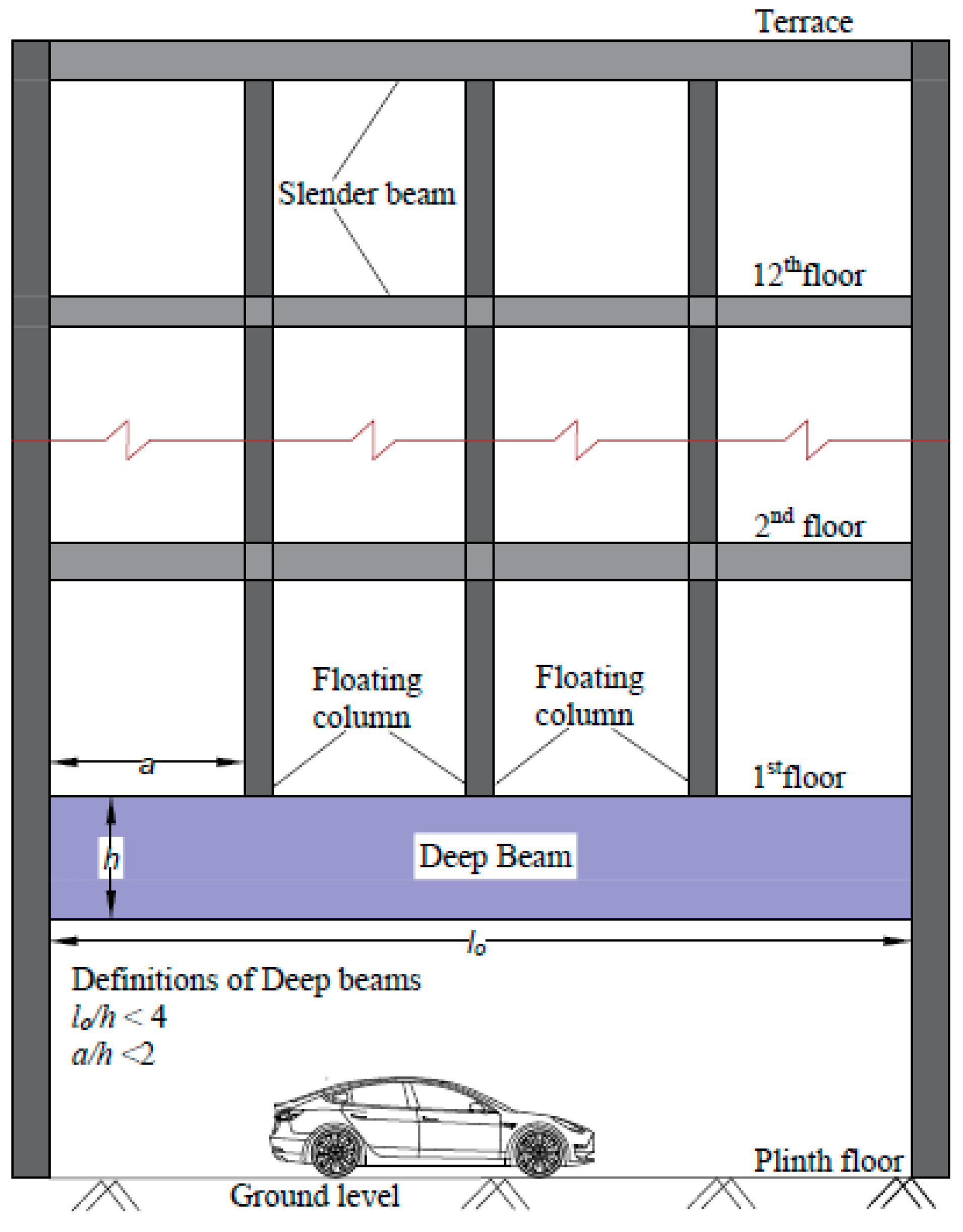
Figure 1. Deep beam in building with multiple floating columns.
Fibers 09 00073 g001
Figure 2. Softening behavior of concrete.
Fibers 09 00073 g002
Figure 3. Deep beam specimen details.
Fibers 09 00073 g003
Figure 4. Details of the specimens: (a) plain concrete with no web reinforcement; (b) plain concrete with 0.3% web reinforcement; (c) fiber reinforced concrete with no web reinforcement.
Fibers 09 00073 g004aFibers 09 00073 g004b
Figure 5. Details of fibers used: (a) macro-synthetic fibers, (b) hooked end steel fibers.
Fibers 09 00073 g005
Figure 6. (a) Test setup and instrumentation of deep beams, (1. controller, 2. UTM of 2000 kN capacity, 3. test specimen, 4. light source, 5. data acquisition system (DAQ), 6. data storage (DIC+DAQ), 7. DIC camera). (b) Schematic diagram of the test set-up, (1. fixed head, 2. loading plate, 3. connecting posts, 4. test specimens, 5. support plate, 6. movable head, 7. hydraulic cylinder). (c) Instrumentation on the rear face of deep beam.
Fibers 09 00073 g006aFibers 09 00073 g006b
Figure 7. (a) Comparison of strain measured using DIC and LVDT, (b) Location of virtual gauge in DIC, (c) Location of LVDT.
Fibers 09 00073 g007
Figure 8. Normalized load-deflection behavior of all the specimens.
Fibers 09 00073 g008
Figure 9. Load-deflection curves of tested specimens: (a) control beam (b) beam with web reinforcement (c) SF 50 beam (d) MSF 50 beam (e) hybrid 50 beam (f) summary.
Fibers 09 00073 g009
Figure 10. Comparison of first crack and peak load after normalization with fcmbd.
Fibers 09 00073 g010
Figure 11. Comparison of energy absorption capacity of all tested deep beams.
Fibers 09 00073 g011
Figure 12. Strains in longitudinal tension reinforcement at mid-span.
Fibers 09 00073 g012
Figure 13. Principal strain contours of tested deep beams at key load points (+ve: tension, −ve: compression).
Fibers 09 00073 g013
Figure 14. Final failure modes of deep beams: (a) DB-F-0, (b) DB-S-0.3, (c) DB-SF-50, (d) DB-MSF-50, (e) DB-HB-50.
Fibers 09 00073 g014
Figure 15. Strain variation normal to the first crack.
Fibers 09 00073 g015
Figure 16. Strain variation normal to critical crack.
Fibers 09 00073 g016
Table 1. Compressive strength properties of concrete.
Specimen IDVf (%)Avg. Cube Strength
fcm (MPa)
Standard
Deviation (SD) (MPa)
Avg. Bulk Density (kg/m3)
DB-F-00.055.62.012256
DB-SF-500.552.52.372279
DB-MSF-500.552.12.402267
DB-HB-500.560.22.172284
DB-S-0.30.052.91.902247
Table 2. Test matrix.
Beam IDFiber Volume Fraction (%)Vertical Web Reinforcement (%)Horizontal Web Reinforcement (%)
DB-F-0000
DB-E-0.3W00.30.3
DB-SF-500.500
DB-MSF-500.500
DB-HB-500.500
Table 3. Mix proportions of SCC (kg/m3).
CementFly AshWaterFine AggregateCoarse AggregateSP aW/B b
3401602158277901.750.43
Note: a superplasticizer, b water to binder ratio (binder = cement + fly ash).
Table 4. Mechanical properties of fibers.
SpecificationHooked End Steel FibersMacro-Synthetic Fibers
Specific gravity7.850.91
Length (mm)3050
Diameter (mm)0.60.5
Tensile strength (MPa)1000618
Modulus of Elasticity (GPa)20010
Aspect ratio50100
Table 5. Summary of test results.
Beam IDfcm
(MPa)
Pcr
(kN)
Δcr
(mm)
Pu
(kN)
Δu
(mm)
Pcr/PuEAC
(kN-mm)
Failure Mode
DB-F-055.6511.52.24812.53.480.632863.8Diagonal Splitting
DB-SF-5052.5677.72.601140.34.650.594562.8Diagonal Splitting
DB-MSF-5052.1432.92.071078.54.930.404344.1Diagonal Splitting
DB-HB-5060.2544.21.931437.65.460.384991.4Diagonal Splitting
DB-S-0.352.9524.72.21970.84.350.544666.2Diagonal Splitting
Note: fcm = compressive strength of concrete in MPa, Pcr = first diagonal crack load in kN, Δcr = deflection at the first diagonal crack in mm, Pu = ultimate load in kN, Δu = deflection at ultimate load in mm, EAC= energy absorption capacity in kN-mm.
Publisher’s Note: MDPI stays neutral with regard to jurisdictional claims in published maps and institutional affiliations.