1. Introduction
In the last years, to exceed the disadvantages of fiber reinforced polymers (FRPs) systems [
1], a new alternative cement-based or lime-based mortar composite material has been developed for external strengthening of reinforced concrete (RC) and masonry structures.
Using combining composite textiles and inorganic matrices, resulting in what is related to with various names: textile-reinforced concrete (TRC), textile-reinforced mortar (TRM), fabric/fiber reinforced cementitious matrix (FRCM), steel reinforced grout (SRG) and others. Reinforcing fabrics/fibers could be made of steel [
2], basalt [
3], polyparaphenylene-benzobisoxazole (PBO) [
4], carbon [
5], aramid or glass [
6] and basalt. Many experimental works are available in the literature on FRCM/SRG-concrete bond tests [
2,
3,
4,
5,
6], flexural strengthening using traditional [
7] and innovative eco-friendly [
8] technique and on axial behavior of confined masonry columns [
9].
The steel reinforcement is one of the most widely used because of its high resistance, good stability and fairly easy installation operations.
Moreover, the literature highlight how fiber reinforcement through plaster affects the behavior of masonry walls at static and dynamic loads [
10,
11,
12].
This paper presents shear bond tests carried out on prismatic masonry specimens concerning two steel SRG systems in order to investigate the debonding phenomenon and performance between the composite material and the masonry substrate. The textile reinforcement used in this investigation are two SRG systems, the first one composite material made of ultra-high tensile strength steel (UHTSS) fibers and the second one made of stainless-steel fibers, both embedded in a mineral mortar.
The physical phenomenon that allows the use of these materials concerns the bond capability that develops between the support (element to be reinforced) and the fiber (reinforcement). Tangential stresses are therefore developed and allow the effectiveness of the whole system.
Moreover, this paper presents numerical modelling of the bond behavior in SRG-strengthened masonry components using interface elements, based on a testing program. To this end ABAQUS finite element (FE) software [
13] is employed to model the specimens used in laboratory tests and shows that difference deriving from numerical and experimental results are acceptable. As known ABAQUS is widely used to simulate several numerical techniques for the analysis of masonry structures [
14] and many other problems.
A bond-slip model available in the literature [
15] has been used and validated for the interface friction between the various elements of the composite (two layers of matrix coupled to the fiber), starting from the observed experimental behavior of reinforced components.
Through comparisons with the experimental tests the FE modelling was validated. In fact, it is necessary, from the many interface laws proposed in scientific literature, to use the law that best represents the physical phenomenon. The parameter used for the validation of the model is the ultimate load. The results highlighted a good agreement of the FE model with respect to the experimental results in terms of the load versus global-slip curve. Modes of failure and all other observations are discussed in detail.
In summary, this paper deals with the experimental and numerical study of the bond behavior of SRG-strengthened masonry systems. The first one was focused on a comparison of direct shear tests of two strengthening systems that use the steel fibers currently available in marketplace. In the second part a computational model has been validated, it will be able to carry out a parametric analysis that can highlight the influence and the role of some factors on the behavior of strengthened specimens.
In order to investigate the behavior of external reinforcement applied on masonry substrate, two different steel fibers and mortars, were used.
2. Direct Shear Tests
2.1. Material and Methods
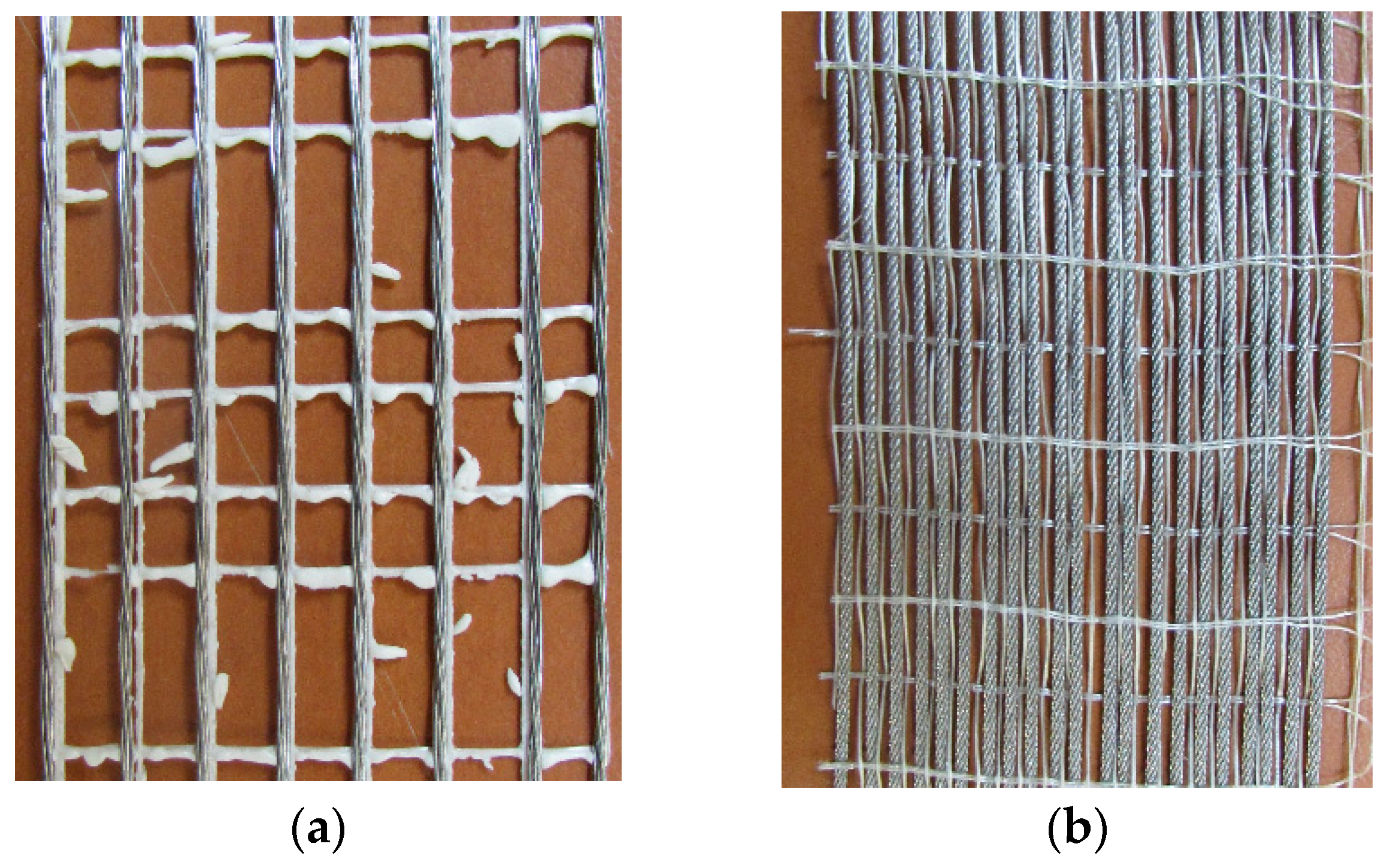
Ten specimens, presented in this paper, were tested to investigate the debonding phenomenon in SRG-masonry joints. The SRG system was made up of inorganic matrix and steel fibers and in this study two different SRG systems were investigated. In particular, the first SRG system was composed of mineral-NHL mortar, containing natural kaolin, bauxite and hydraulic lime binders and the UHTSS galvanized steel fibers as shown in
Figure 1a (called SRG_1), while the second composite system of lime-based matrix and Stainless steel fibers is shown in
Figure 1b (called SRG_2).
The UHTSS fiber was constituted of a unidirectional sheet made of high strength galvanized twisted steel micro-cords held together by a glass fiber micro-mesh. Each micro-cord is composed of five filaments. Three are wrapped around the other two filaments with a high twisted angle. The cross-sectional area of the single cord is 0.538 mm
2. The stainless-steel fibers were made of stainless strands, particularly resistant to rising damp and/or exposure to aggressive environments, with 0.47 mm
2 of cross-sectional area of the single strand. In
Table 1 the physical and mechanical properties of the two different steel fibers provided by the manufacturer are reported [
16,
17], while in
Table 2 are summarized the mechanical properties of the matrix evaluated on three specimens for both inorganic matrixes adopted, in accordance to EN 12190:1998 [
18] for the compressive strength and to EN 1015-11:2019 [
19] for the flexural tensile strength. Additional information was reported in the technical data sheets provided by the manufacturer.
All masonry units adopted have the same cross section (
b = 250 mm;
h = 125 mm) and length of
L = 315 mm. The composite strip was applied on the two opposite face masonry units as reported in
Figure 2, moreover, it was applied starting of 30 mm from the edge of top face of the masonry units, in the center with respect to the width of the specimens.
The steel fibers were embedded in two layers of 3 mm of inorganic matrix. The composite strip was lb = 260 mm in length. The nominal width bw of the composite strips was 50 mm; however, using the UHTSS fibers there were eight micro-cords, while with stainless steel fibers there were twenty-five steel cords in the nominal width. Before the application of the composite SRG, the masonry prisms were soaked opportunely and completely in water in order to avoid the absorption of the mortar water.
All operations were carried out at the University of Calabria in the Laboratory of Material and Structure (Department of Civil Engineering).
2.2. Test Set-Up
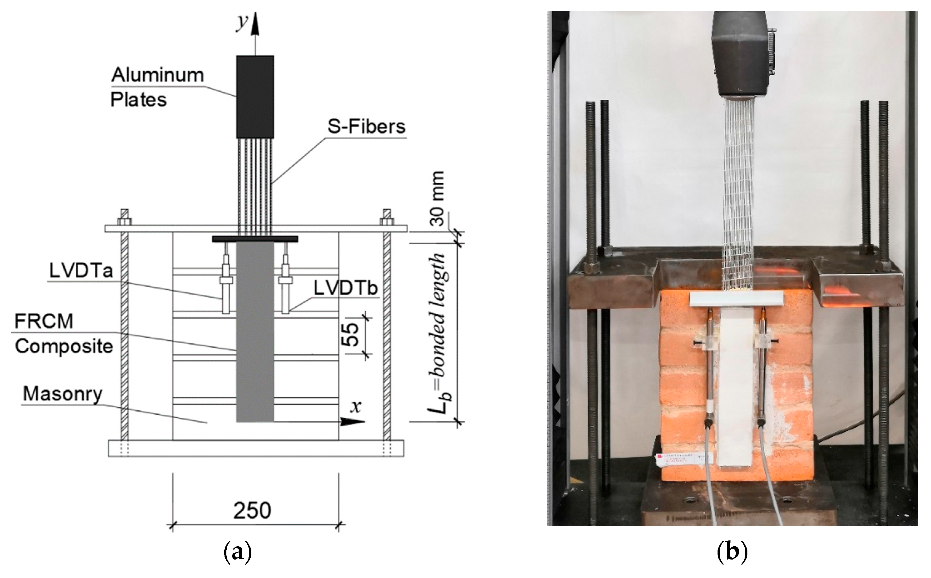
The details of test set-up adopted in this experimental campaign is shown in
Figure 2a,b. The classical push-pull configuration was adopted for 10 single-lap shear tests, in which the composite fibers were pulled while the prisms were restrained. Two aluminum plates of 3 mm thickness were glued to the end of the steel strip by a thermosetting epoxy resin to grip the bare fibers during testing in order to assure a uniform pressure on the gripped micro cords during the test. This technique was used so that the steel strip can slip outside of the aluminum plate area. Two linear variable displacement transducers (LVDTs) were attached on the face of the specimen adjacent to the composite strip which will be named LVDTa and LVDTb (
Figure 2b). The slip
g, defined as the relative displacement between the fibers near the composite bonded area and close to the surface masonry prism, was measured in all tests. A thin aluminum L-shaped plate was attached near the bonded area (at the top of masonry prism). The rate adopted was 0.2 mm/min in all tests and it were conducted in stroke control and all data (load and global slip) were recorded using an acquisition frequency of 10 Hz.
Specimens were named following the notation DS_X_Z, where the direct shear (DS) indicated the adopted test typology, X indicated the type of steel fibers used (U = UHTSS or S = Stainless) and Z indicated the specimen number.
3. Discussion and Results
3.1. Single-Lap Shear Test Results
In this section, the main experimental results are critically discussed. The comparison between the two types of strengthening systems is done in graphic and numerical terms by commenting on the different bond behavior.
With reference to the direct shear test,
Table 3 (in round brackets the Coefficient of Variation) reports the maximum load reached by each specimen (
), the average global slip (
) at maximum load measured by the two LVDTs as well the ultimate global slip (
), maximum stress in the textile (
), stress/resistance ratio, inclination of the elastic branch and failure modes. The peak stress is evaluated using Equation (1):
where
is the peak load,
is the area of each cord, and
is the number of bundles in the longitudinal fiber cords.
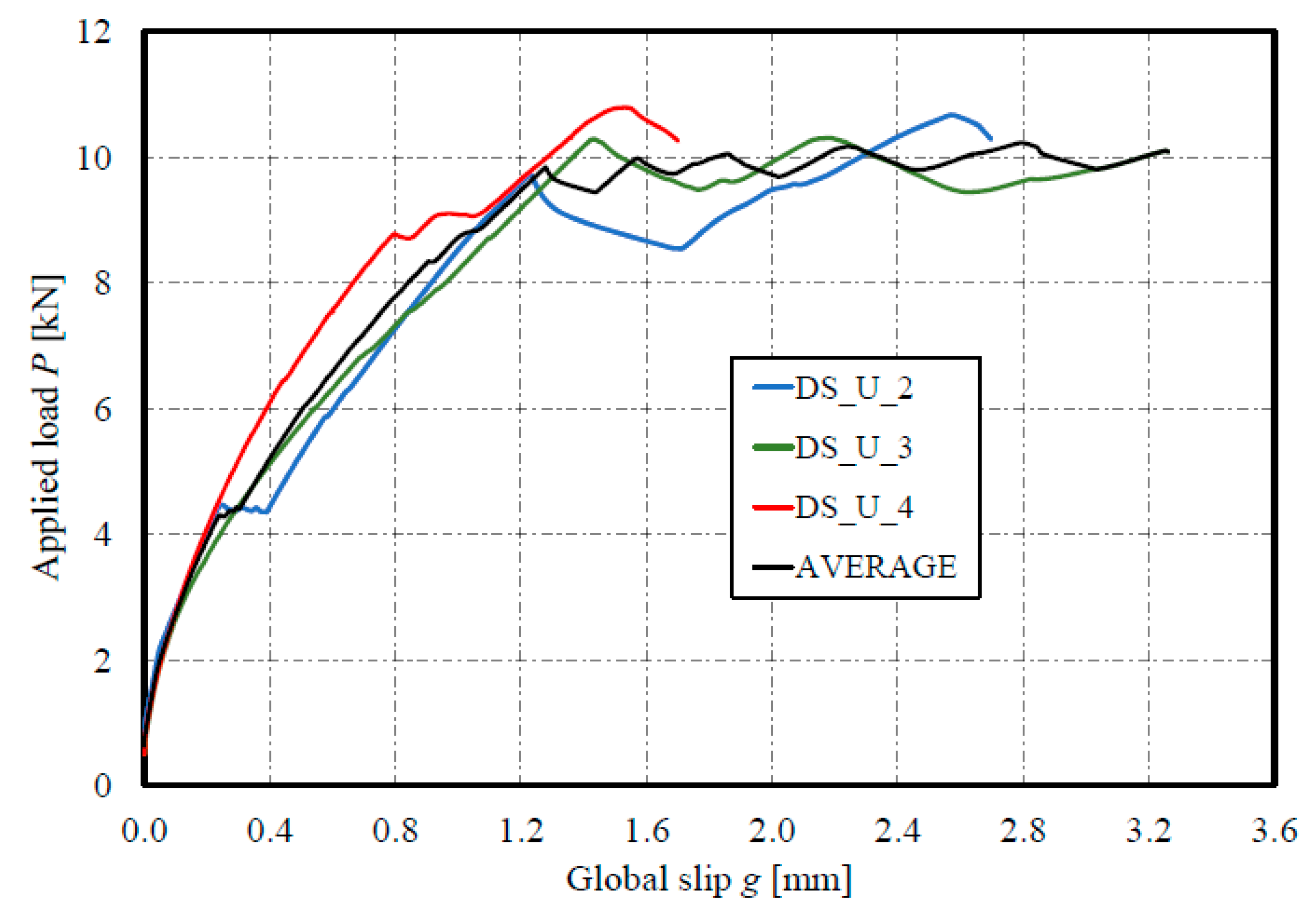
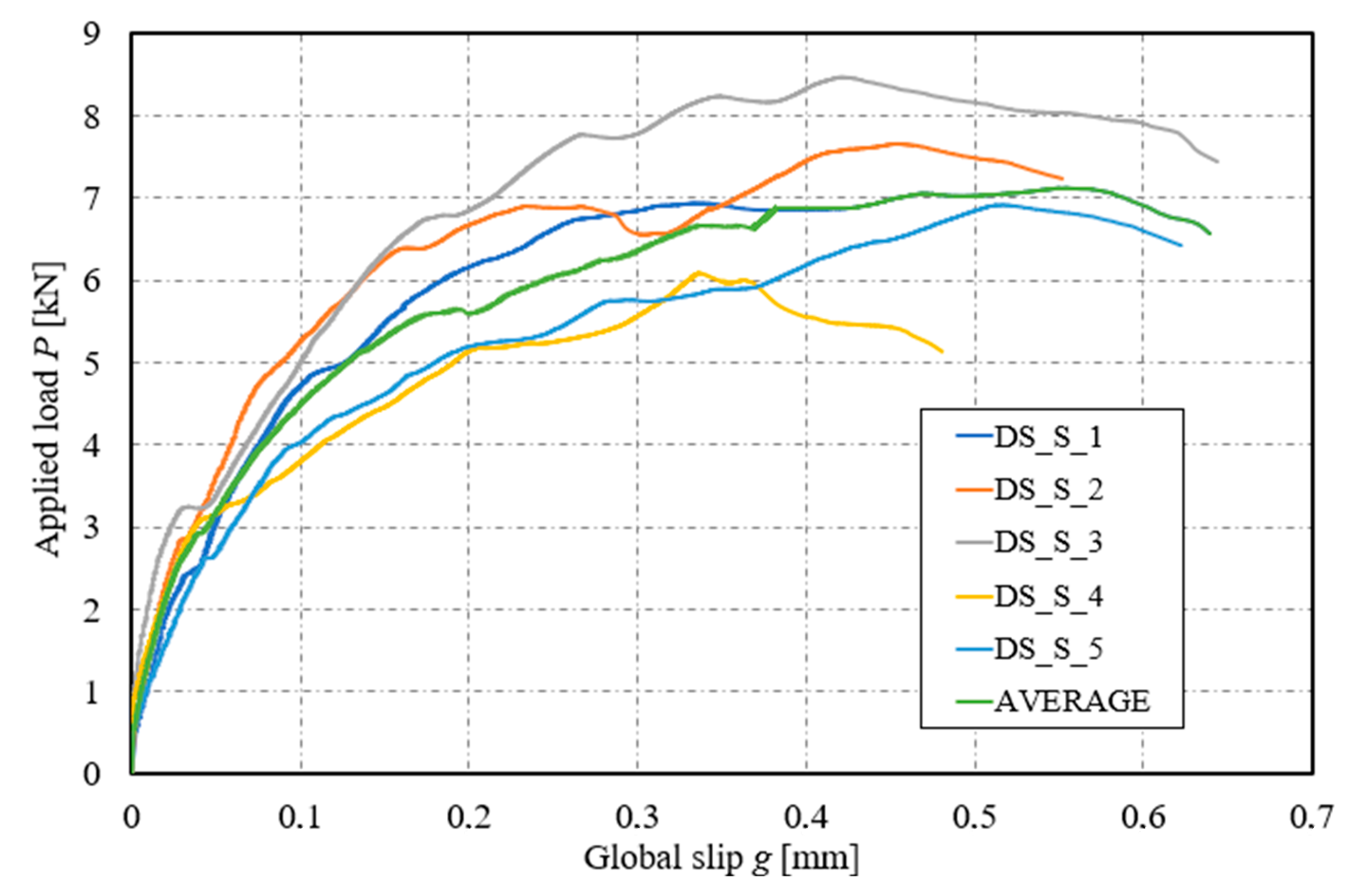
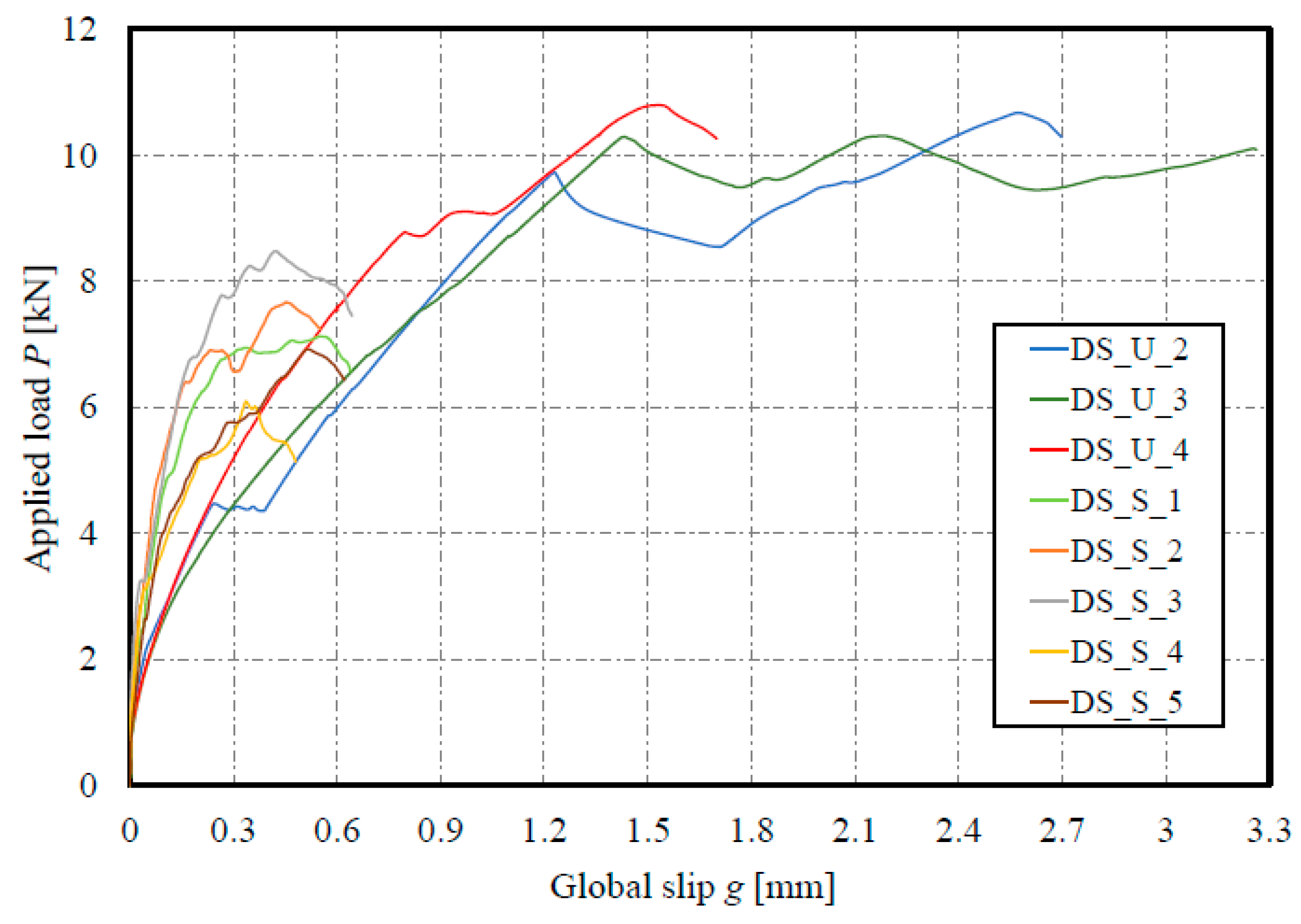
Figure 3,
Figure 4 and
Figure 5 show the applied load
P to global slip
g response of the single-lap shear specimens for each SRG system and overall comparison. The load responses are also shown in terms of stress
σ by Equation (1). The average curves (AVG) of the tests are also shown in the same figures.
The experimental evidence suggests that the initial part of the load response is represented by a linear branch associated with elastic behavior of the bond between the fibers and the matrix. A slight reduction in stiffness occurs where the interface between the steel fibers and the matrix experiences some micro-damage. After the maximum load P* is reached, further increases in global slip generally result in a near-constant applied load until a sudden and rapid degradation of load occurs with no distinct softening response. The tests carried out showed that the two reinforcement systems have a different behavior.
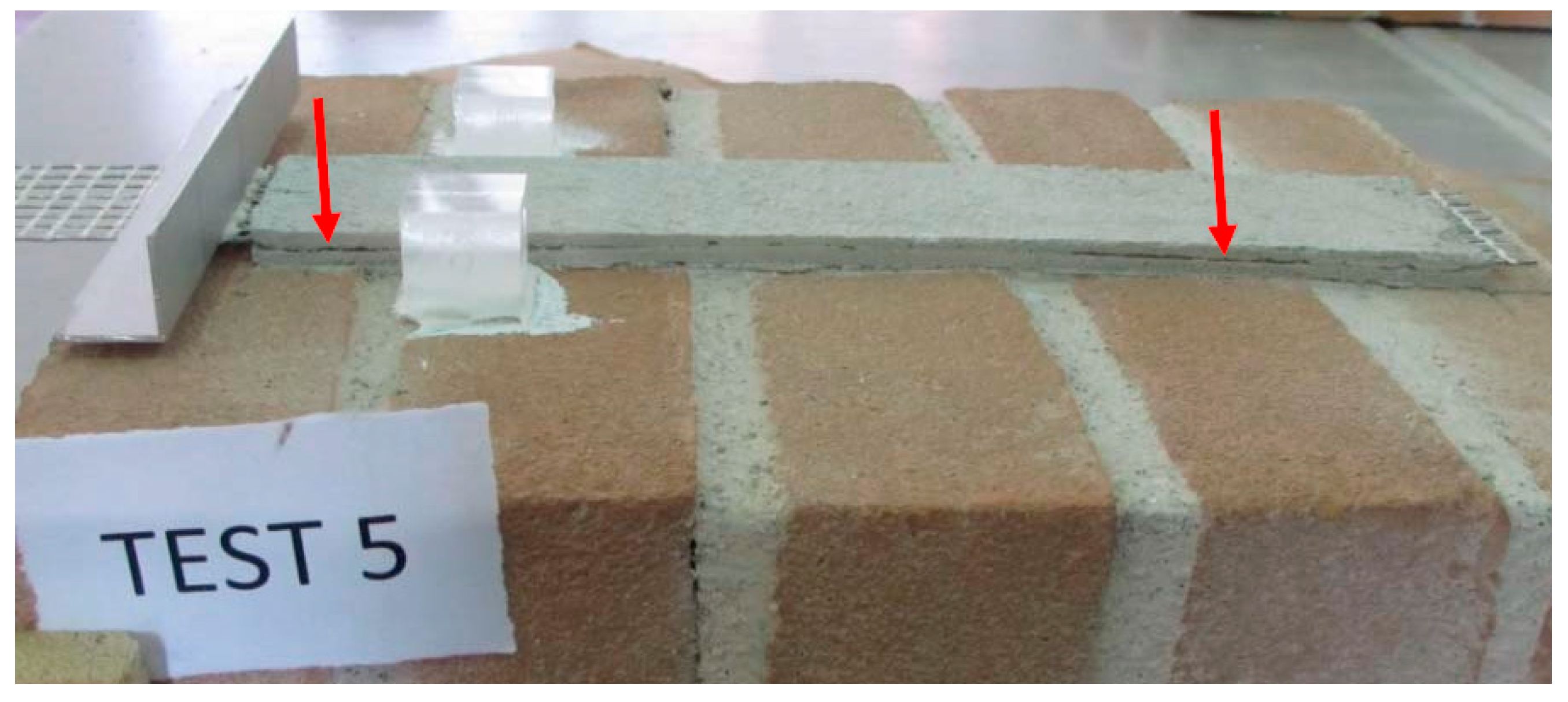
In detail, Tests DS_U_1 and DS_U_5 showed a lower maximum load with respect to the other three specimens. The different behavior is due to a not perfect casting preparations and/or the damages existing on the composite strip.
Figure 6 shows the existing damage in specimen 5. These two specimens (DS_U_1 and DS_U_5) are not considered in average curve (AVG) and the other calculations. It should be noted from
Figure 5 that the SRG_1 equipped with the UHTSS fibers reach a greater applied load with respect to SRG_2 systems. The maximum applied loads P
max achieved from the SRG_1 are due to a lesser steel fiber sheet density and consequently at a greater impregnation between the single cords and the external/internal matrix layer. The experimental results evidenced, for both SRG systems, that the first branch is linear-elastic and the second branch is almost constant to the maximum applied load with greater increment in term of global slip s with respect to the first part of the curve. At the end, there is a sudden and rapid degradation of the applied load without distinguishing the softening response. At the same time, the results obtained from the second strengthening system (SRG_2) showed the same level of load for all tests.
The stress/resistance ratio can be considered as a factor that measures effective utilization of the bond capacity of the composite system compared to the tensile strength of the dry fiber. The results, correlated to the different impregnation capacity of the two fibers (different weight per unit area), shows how the SRG_1 system is more effectiveness than the SRG_2 system. In numerical terms the failure strength of two dry steel fibers and the maximum tensile stress in the textile are reported in
Table 3. The mean values of the tests results considered for SRG_1 and SRG_2 systems are 82.00% and 41.11%, respectively.
The first strengthening system showed greater global slip before detachment compared to the second, respectively 2.56 mm and 0.59 mm, in average values. The reinforcement with stainless steel fiber has a slope of the elastic branch much greater than the other. Another interesting aspect concerns the load curve; for the first reinforcement system the loading path does not present a significant segment of softening in the terminal phase, with behavior similar to FRP. In the stainless-steel system this phenomenon is less evident.
Further considerations are made on the different crack pattern due to the mechanical characteristics of the mortars used, as shown in the following
Section 3.2 on failure modes. The different behavior of the two composite systems turn into a different tangential–global slip interface law, which describes the bond behavior detailed in the Chapter 4.
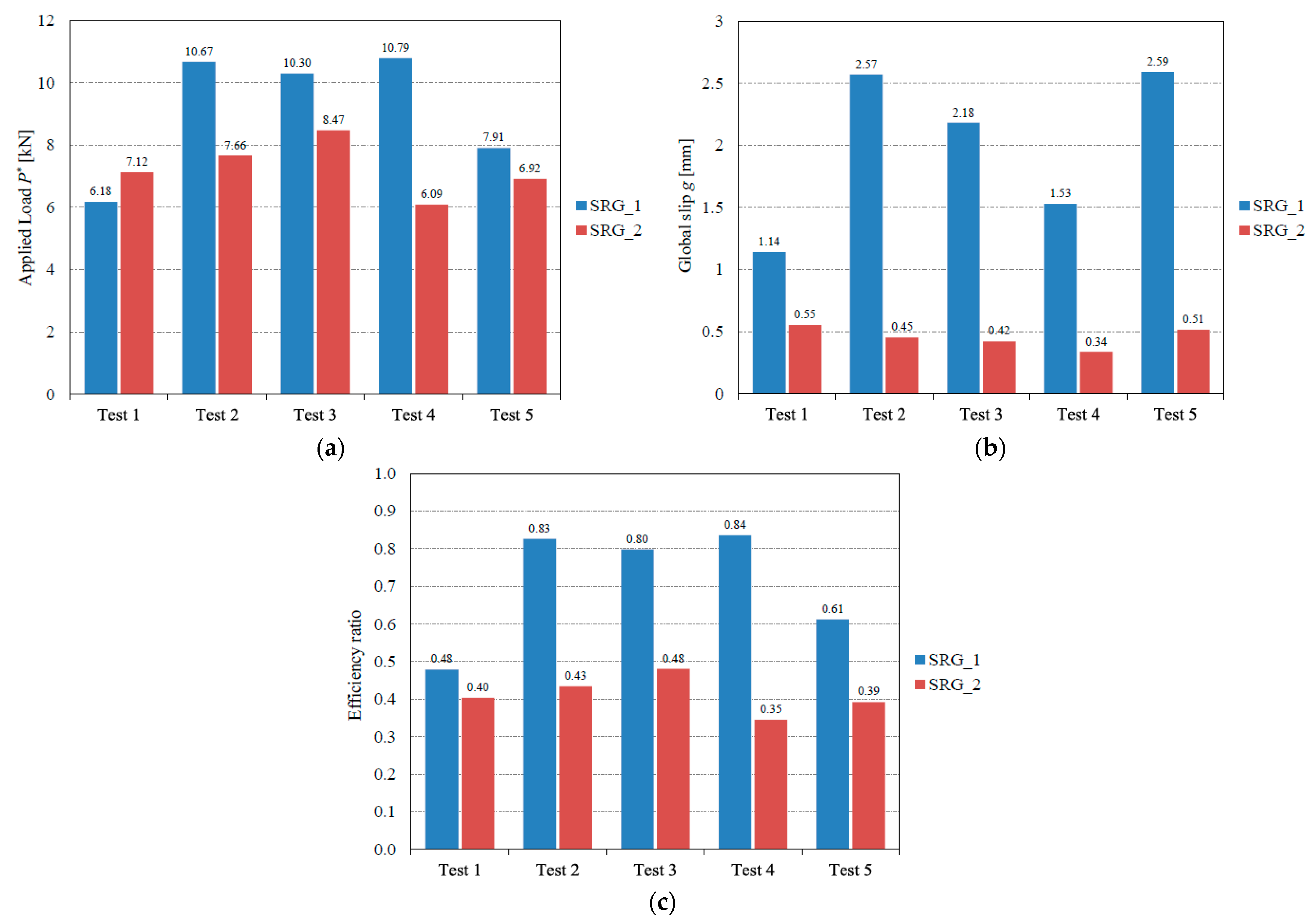
The comparison between the two groups of tests are summarized in the bar chart of
Figure 7a–c for the three main parameters: applied load, global slip at maximum load and efficiency ratio normalized to 1.
3.2. Failure Mode
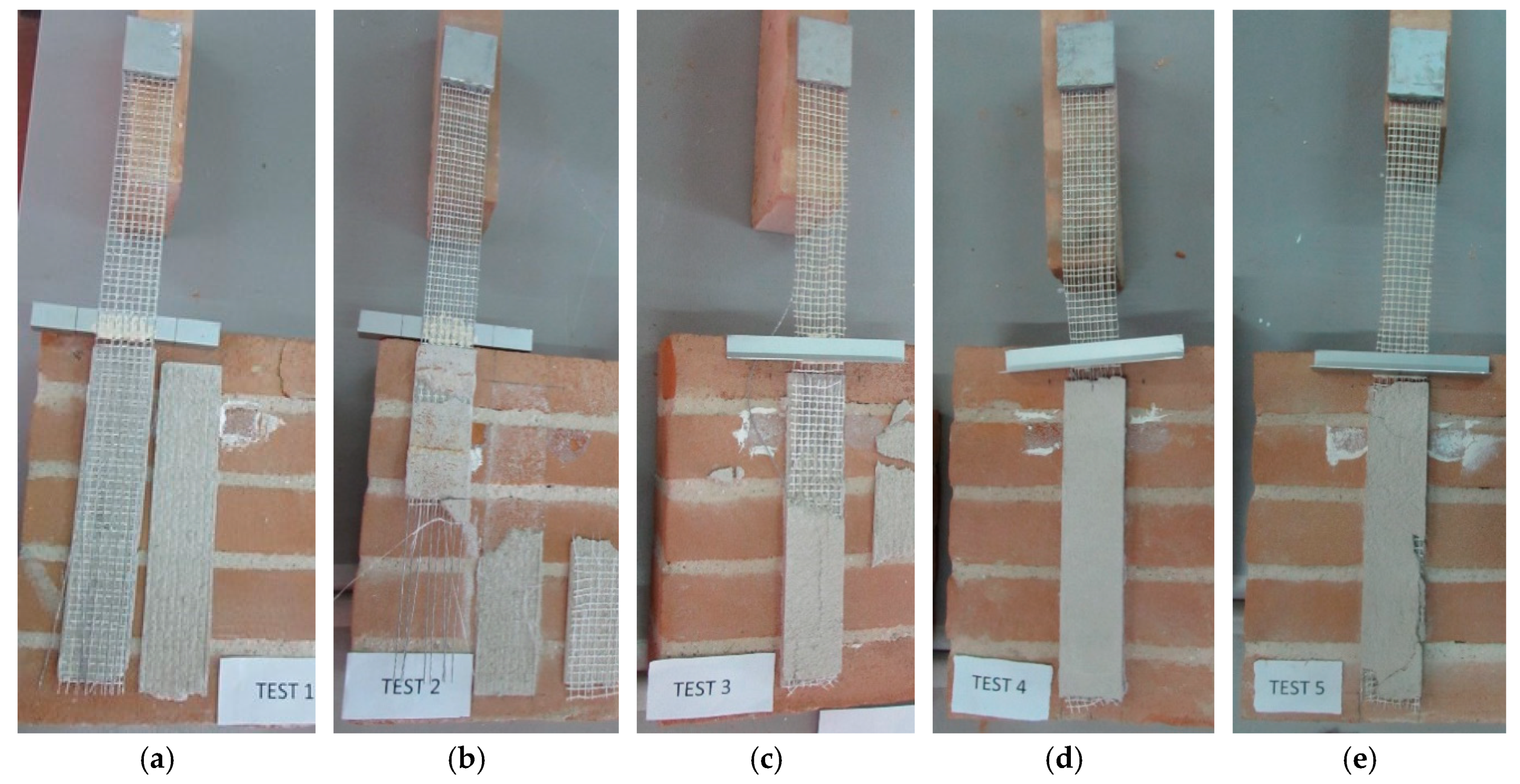
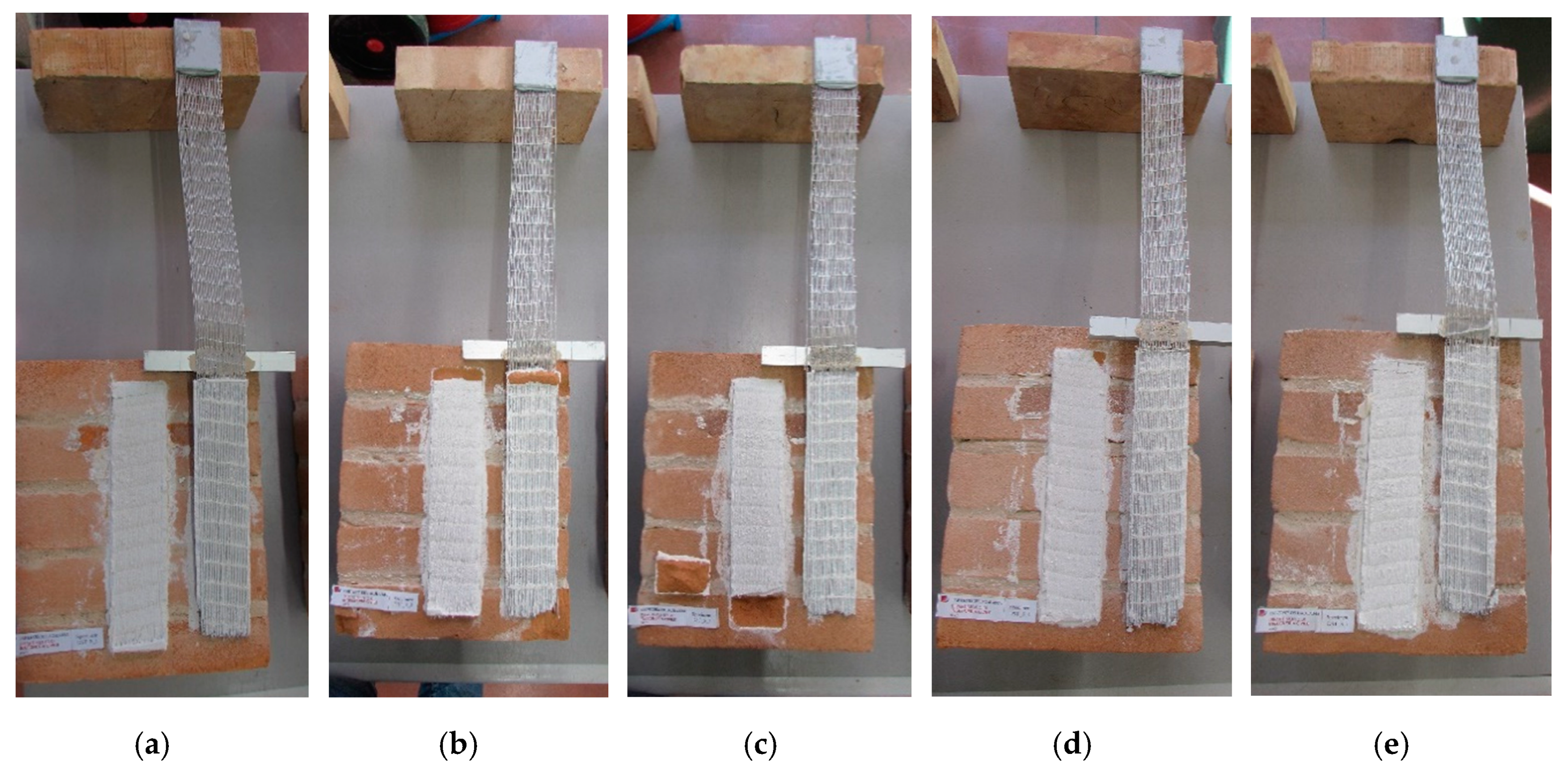
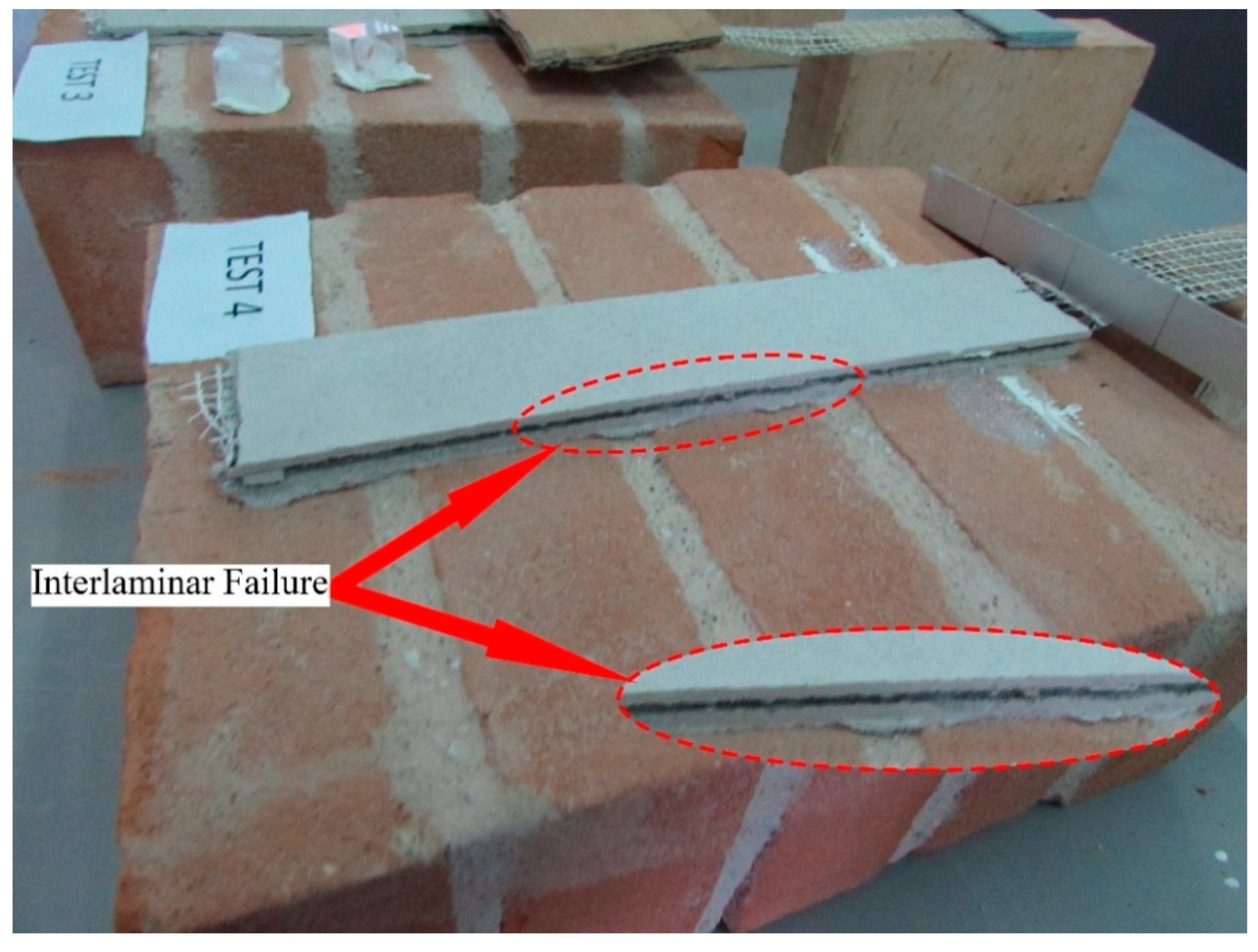
In
Figure 8 and
Figure 9 the typical failure mode of both SRG systems are reported. For all specimens, an interfacial crack formed along the steel sheet (see
Figure 10a,b). Debonding occurred at the internal steel sheet-to-mortar interface and it was the result of matrix fracture between the steel fibers. This type of failure in literature is called interlaminar-failure (failure mode “C”). Similar failure modes showed in
Figure 11 were also observed in Sneed et al. [
20].
In particular, the SRG_1 composite system, during the tests, at the increase of global slip, presented a crack pattern along the entire bonded length on the external matrix layer (
Figure 10c). Instead, the second composite system, on the external matrix layer did not present any crack except for the formation of a small crack in the upper part of the composite strip (
Figure 10d). Probably this phenomenon increases in stiffness in the first branch but reduces the second branch denoting lesser global slip s with respect to the first composite system (
Figure 5).
Due to the different mechanical tensile characteristics of the mortars, there are different trends in the load–global slip curves of the two systems. In particular, the graph in
Figure 3 shows a trend with irregularities and small load losses. This aspect is due to the greater cracking and width of the cracks themselves during the execution of the test. Instead for the system 2 the curves are more linear and homogeneous, in line with a smaller and less cracking of the external layer of mortar.
4. Finite Element Model
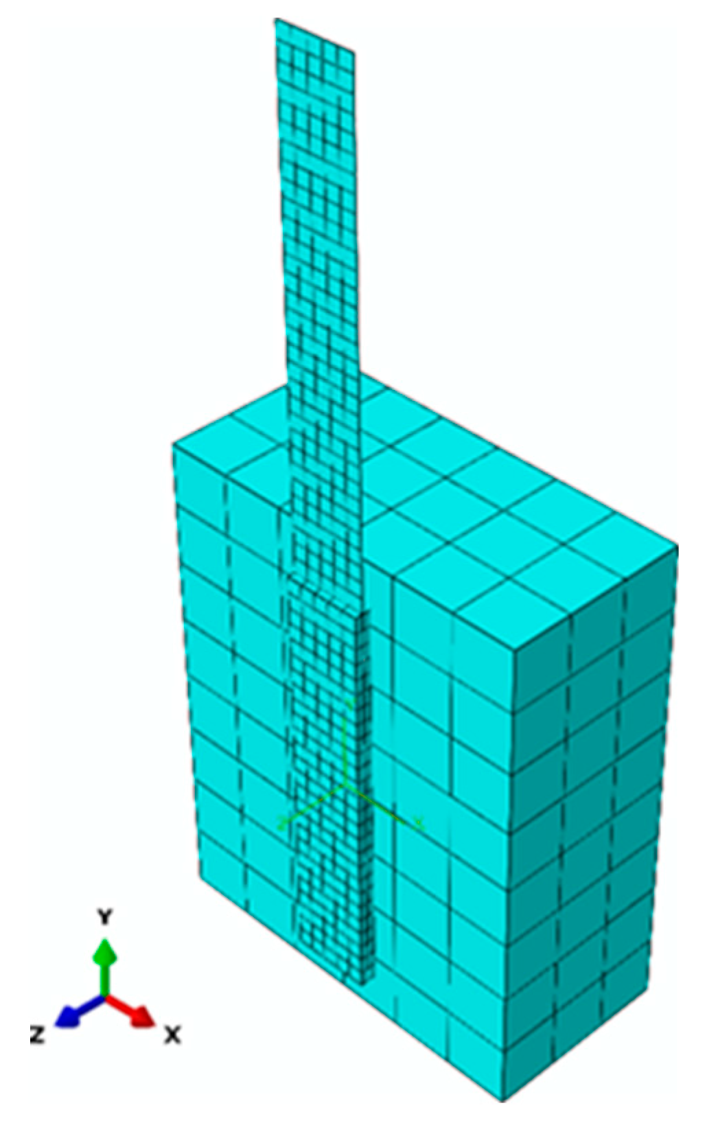
ABAQUS software has been used to perform the analysis by means a macroscopic three-dimensional (3D) finite element (FE) approach. Brick, mortar joints (masonry) and fine-grained mortar are modelled by solid continuous elements using an ABAQUS C3D8R element with linear interpolation.
The brick and mortar can be modelled as a unique homogeneous material; this technique is called macro model approach as reported in Murgo and Mazzotti [
9]. This assumption is acceptable because the masonry results very rigid inside the contrast system and considering that the applied shear load does not reach high values. Therefore, the masonry works at lower values of its compressive strength during the tests. The SRG strengthened system, composed by steel sheet, is also assumed as an equivalent solid element (C3D8R) having rectangular section, and as a homogeneous elastic material until failure.
Figure 12 shows the mesh adopted in this study. The analyses were performed using different mesh sizes. The sensitivity analysis of the mesh allowed to obtain a model with a balance between computational efforts and reliable solution.
The analysis is performed with displacement control, increasing the displacement in the load end of the steel fibers. According to experimental tests, the load applied is simulated with a monotonic incremental law (trend).
The dnamic/explicit analysis package by ABAQUS was used to perform the nonlinear calculation. It was chosen to simulate a quasi-static analysis using an adequate mass scaling factor.
To simulate and take into account the damage of matrix, the concrete damage model (CDP) was used [
21,
22]. The model is suitable for the analysis of other quasi-brittle materials, such the mortar used in the FRCM and SRG applications, to capture the effects of irreversible damage.
The degraded response of mortar is characterized by two independent uniaxial damage variables, which are assumed to be functions of the plastic strains. The concrete behavior in terms of stress–strain relations under uniaxial tension and compression loading are summarized in
Figure 13.
Equation (2) indicates the damage variables for tension (
) and compression (
), the equivalent plastic strains for tension (
) and compression (
) and the initial (undamaged) elastic stiffness of the material (
).
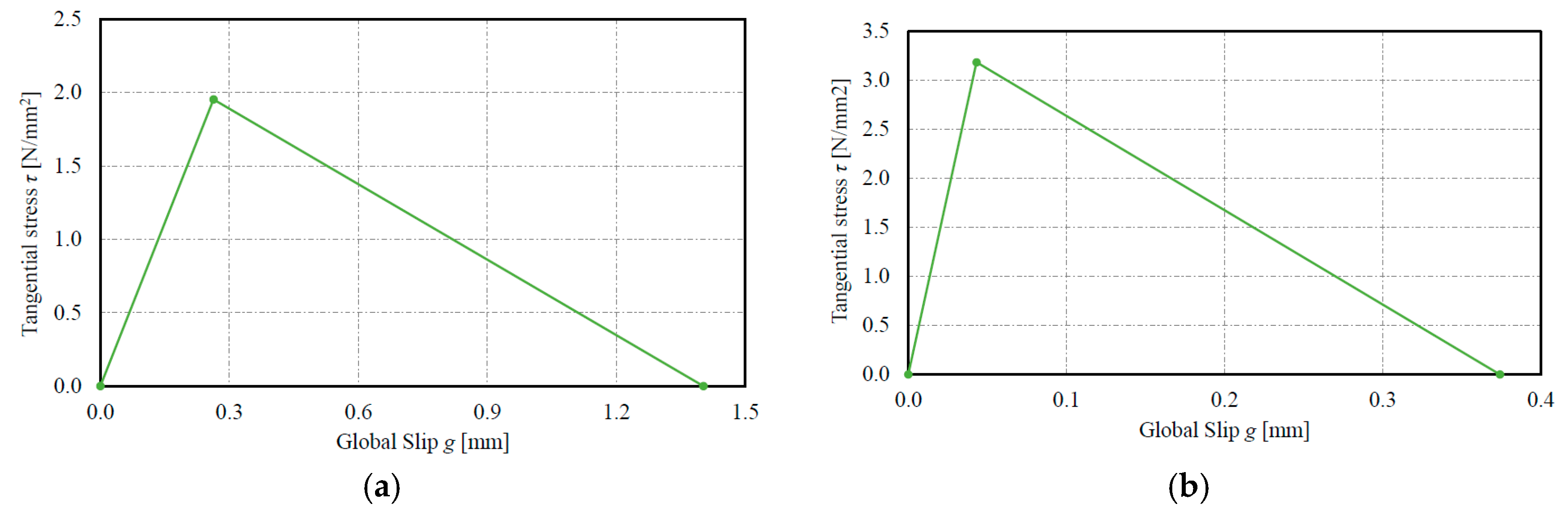
The bond between the reinforcement and the masonry is defined by a shear stress-slip relation (
Figure 14a,b). This relation plays a key role in describing the bond behavior between fiber and masonry, and it was characterized according to Carozzi et al. [
15]. This method is based on the friction that occurs between the external mortar layer and the steel sheet. The interface law is adopted in the model and inserted between fiber and the second layer of matrix, while a perfect bonded constraint is ensured between the internal layer of matrix and masonry member. The bi-linear relationship is defined by the following Equations (3)–(5):
Specifically, Pe is the load at the end of the elastic phase in the P* − g* relationship, ge the corresponding global slip; k1 and k2 the elastic stiffening and the slope of softening branch in the interface law, respectively. Finally, bw, Ef and Af are the nominal width of the strip, the elastic modulus of the fibers and the nominal area of the fibers.
The values of the interfacial bond–slip law for both SRG systems are summarized in
Table 4. The values that characterize the materials and placed in the software are described in a previous Section (Discussion and Results).
5. Experimental and Numerical Comparisons
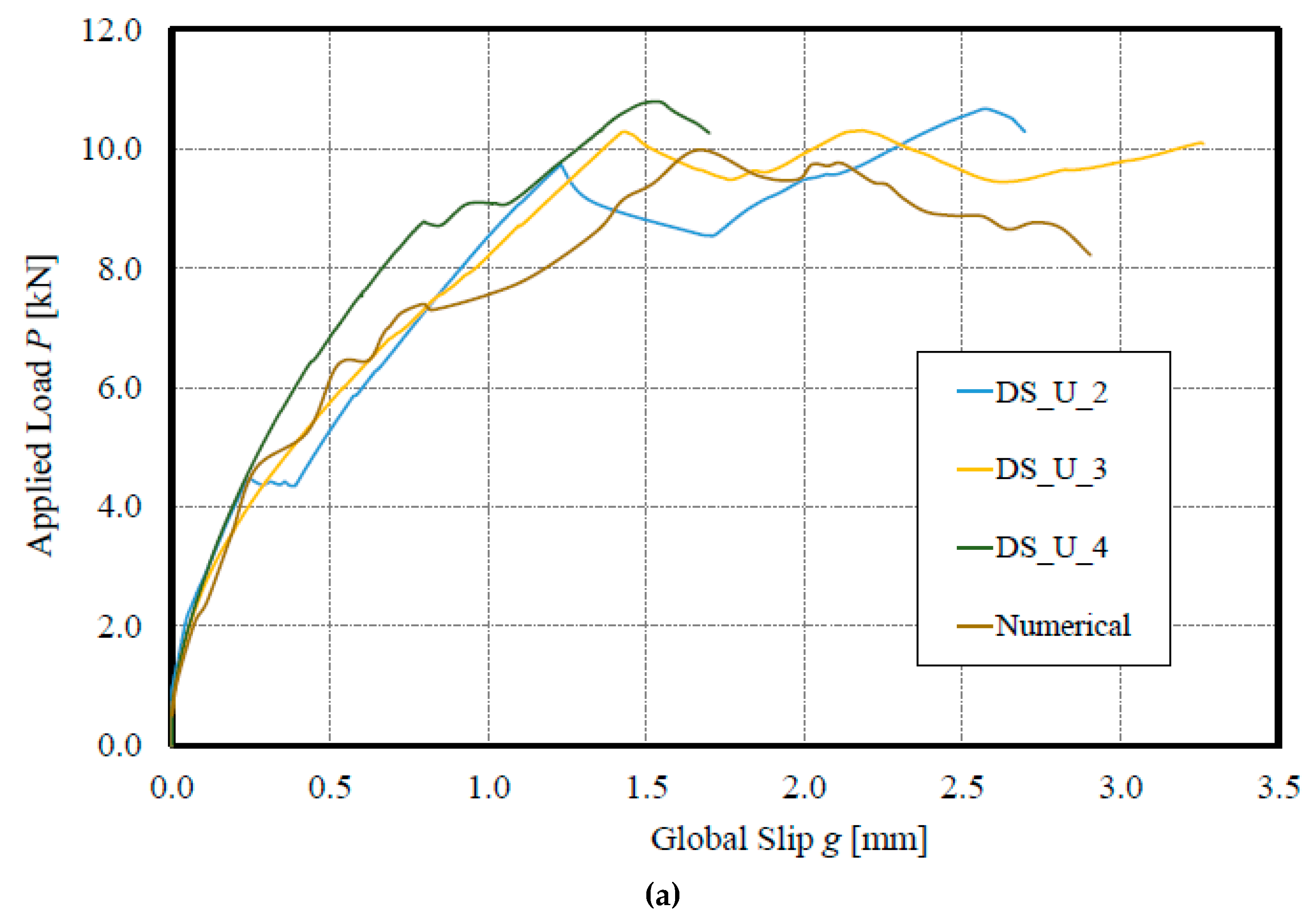
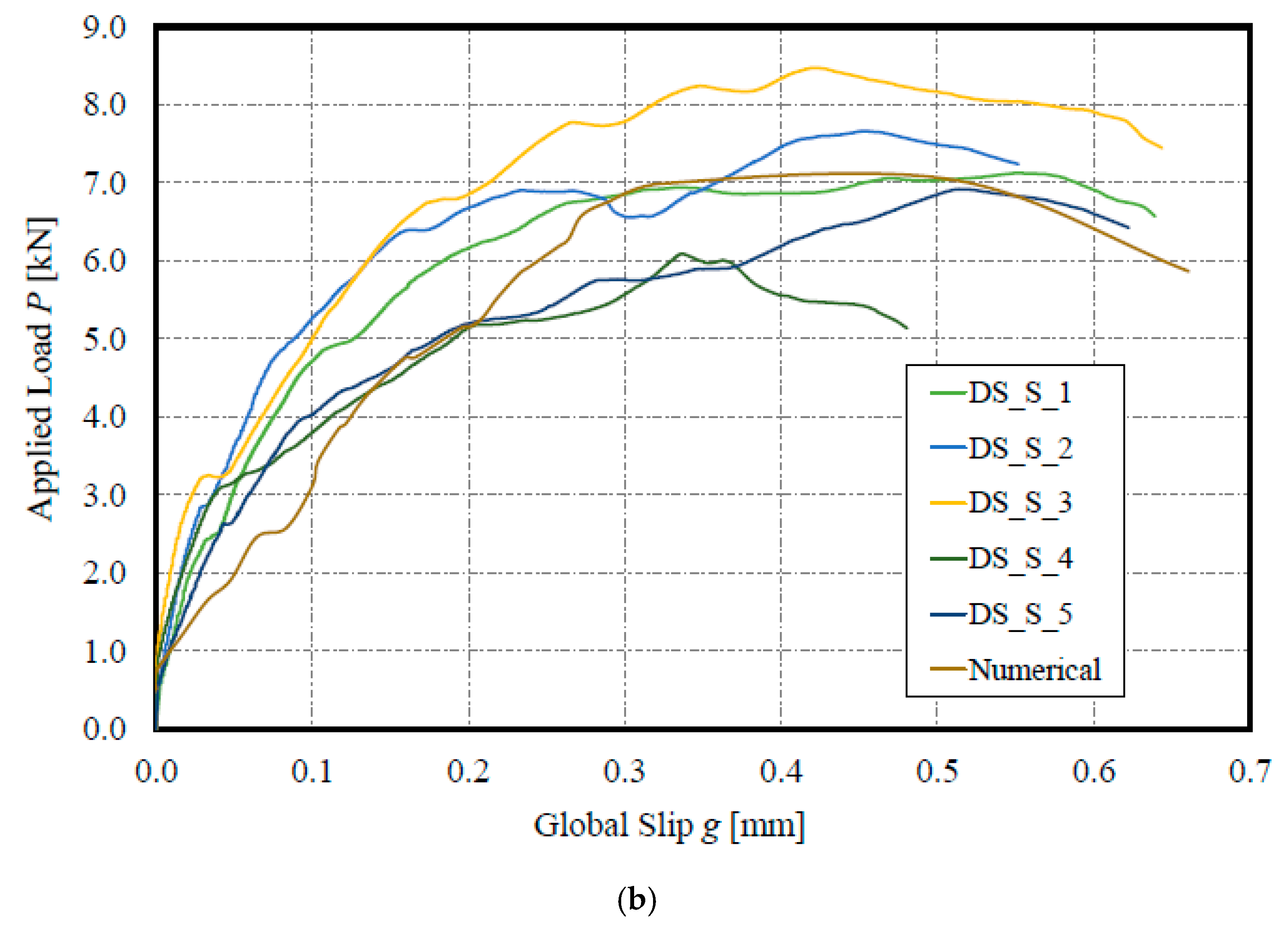
The implemented numerical procedure was adopted to perform a numerical analysis of SRG system about the debonding phenomenon in SRG-masonry joints. A comparison between numerical predictions and experimental results, both described in this paper, was made in terms of applied load P–global slip g diagrams and cracking configurations.
In
Figure 15a,b, it was reported the load–slip curve of the numerical model in order to compare it with the curves experimentally measured. The comparison shows a good/optimum agreement in terms of maximum load reached and maximum global slip, in relation to the three best experimental curves.
Peak load values are predicted with good accuracy for DS_U_2, DS_U_3 and DS_U_4 (9.98 kN is the numerical value; 10.67 kN, 10.30 kN and 10.79 kN are the experimental values) with an error of −6.46%, −3.10% and −7.50%, respectively.
The same considerations can be made with the SRG_2 composite system obtaining the following values: 7.12 kN, 7.66 kN, 8.47 kN, 6.09 kN 6.92 kN for DS_S_1, DS_S_2, DS_S_3, DS_S_4, DS_S_5 in experimental tests, that compared with the numerical results (7.04 kN) provide errors of −1.12%, −8.09%, −16.88%, +15.59% and +6.94%, respectively.
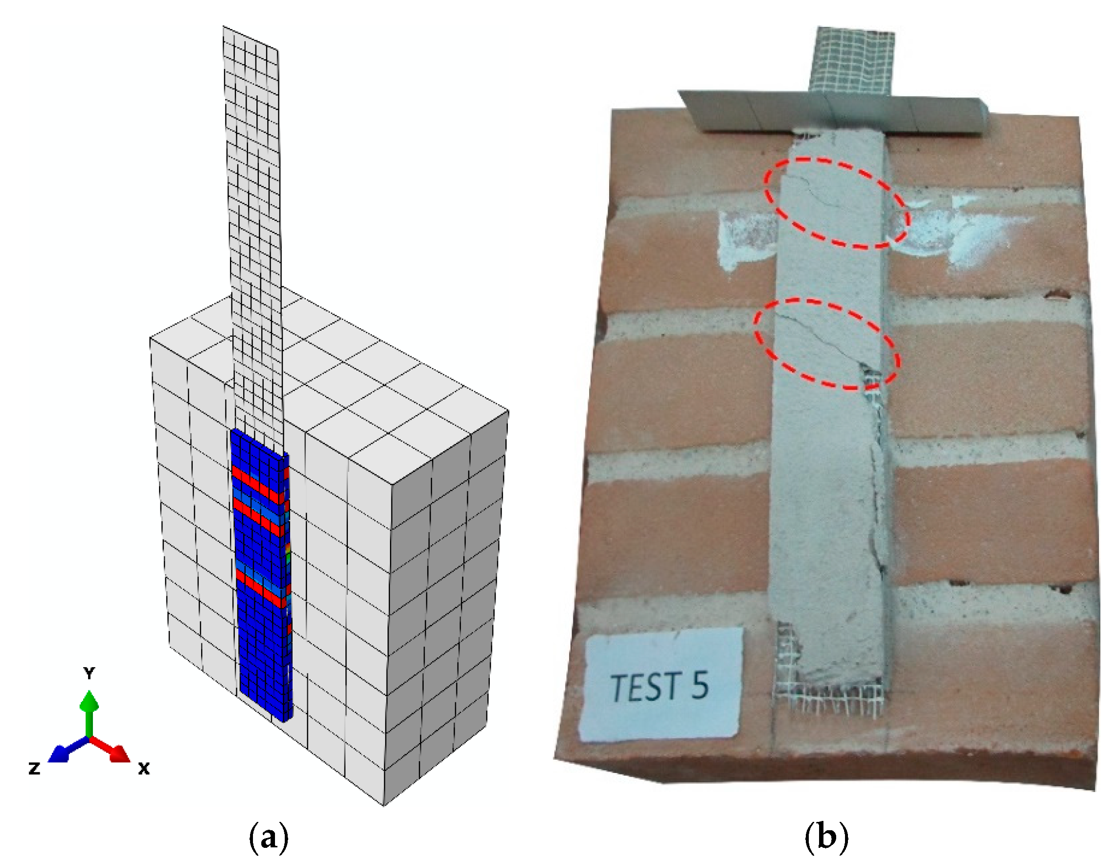
Finally, the comparison reported in
Figure 16 evidences that the cracking pattern obtained by the numerical procedure is in good agreement with the experimental one.
6. Conclusions
In the first part, a study on the bond behavior of a specimens group under shear loads (direct single-lap shear tests), in relation to the innovative SRG system used in the repairing/strengthening field was developed. The following concluding remarks can be drawn:
- -
The SRG systems can be considered as one of the best methods of strengthening in terms of performance.
- -
Typical failure modes involve debonding at fiber/second layer of mortar without detachment of the substrate, like most of the results obtained in other works, for both Steel reinforcements.
- -
Excellent stability of the UHTSS and Stainless reinforcement package under stress as well as ease installation in the application process.
- -
Different behavior in terms of maximum load and slip due to the different mechanical properties of steel and mortar used.
- -
Large influence of the capacity of impregnation of the fibers in the bond and reinforcement.
In the second part of the paper, a 3D FE model to reproduce the global behavior and to validate an appropriate bond–slip law was defined. The numerical simulation is in satisfactory agreement with the experimental results in terms of applied load–global slip and failure mode. Numerical results fit the experimental results with excellent accuracy. The 3D FE model can be useful to carry out a parametric analysis.


