Modeling the Behavior of CFRP Strengthened Concrete Beams and Columns at Different Temperatures
Abstract
1. Introduction
2. Literature Review
3. Finite Element Modelling
3.1. FRP Strengthened Concrete Beams at Room Temperature (RT)
3.2. FRP Strengthened Concrete Beams at 100 °C
3.3. FRP Strengthened Concrete Beams at 180 °C
4. Finite Element Modelling for Columns
4.1. FRP Strengthened Concrete Columns at Room Temperature (RT)
4.2. FRP Strengthened Concrete Columns at 100 °C
4.3. FRP Strengthened Concrete Columns at 180 °C
5. Finite Element Analysis Results and Discussion
5.1. FRP Strengthened Concrete Beams at Room Temperature (RT)
5.2. FRP Strengthened Concrete Beams at 100 °C
5.3. FRP Strengthened Concrete Beams at 180 °C
5.4. FRP Strengthened Concrete Columns at Room Temperature (RT)
6. Conclusions
- (1)
- The FE results are in generally agreement with the experimental results for all temperatures. The maximum discrepancy was 27%.
- (2)
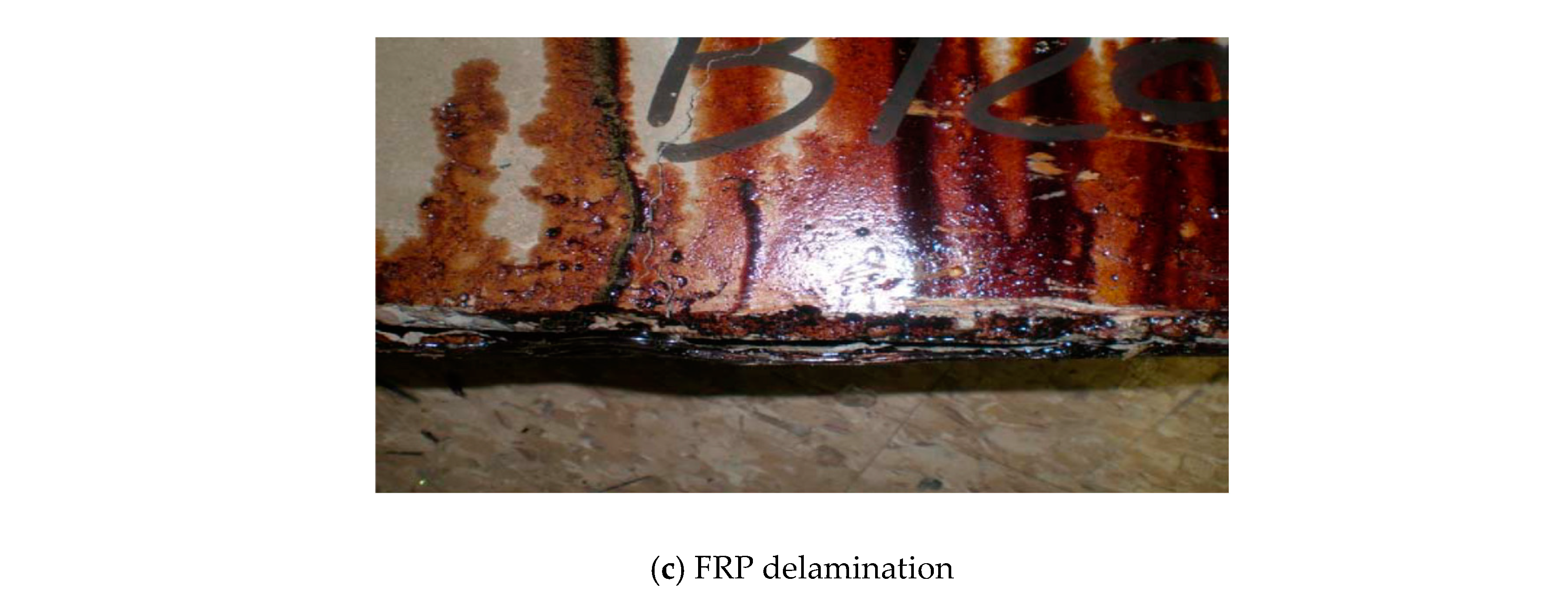
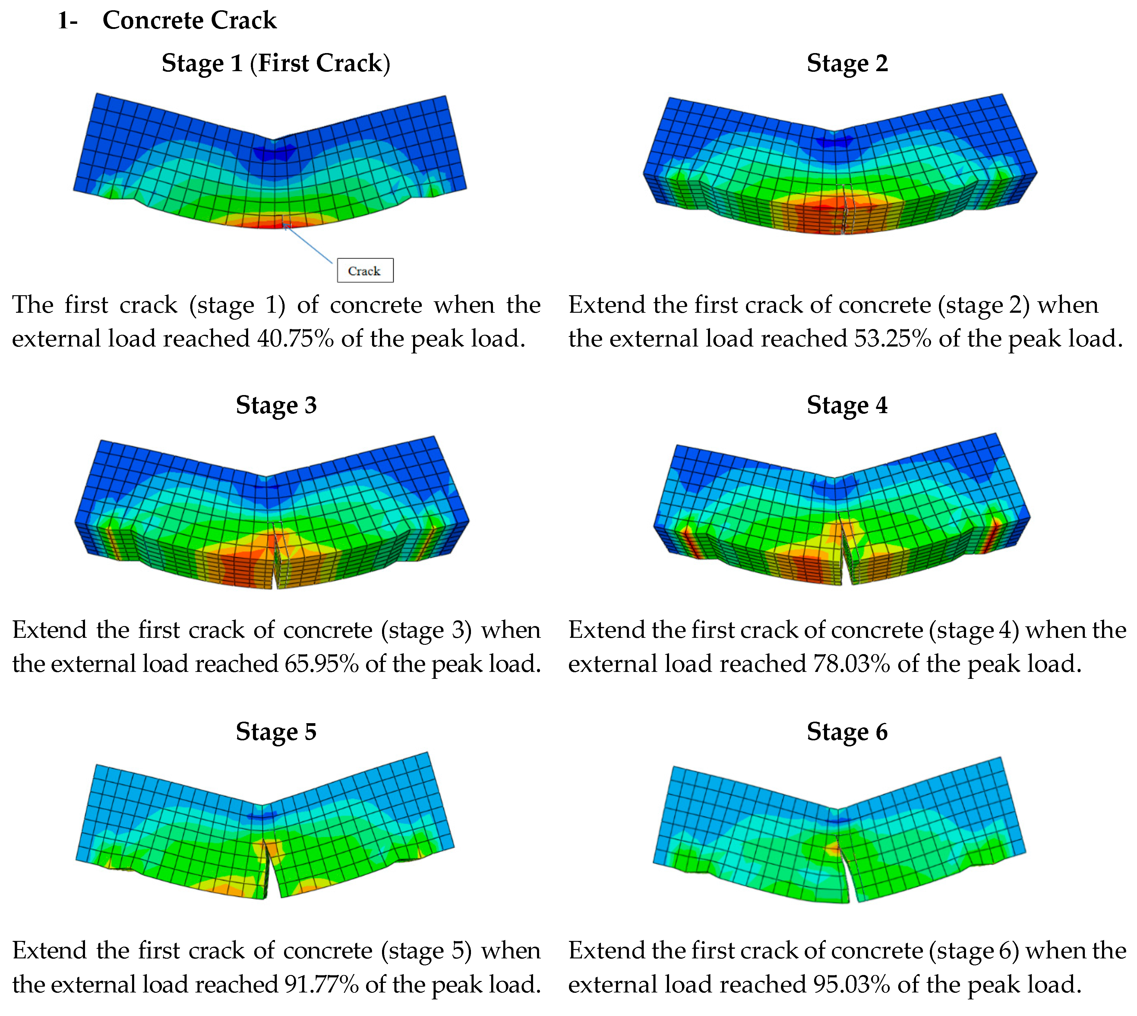
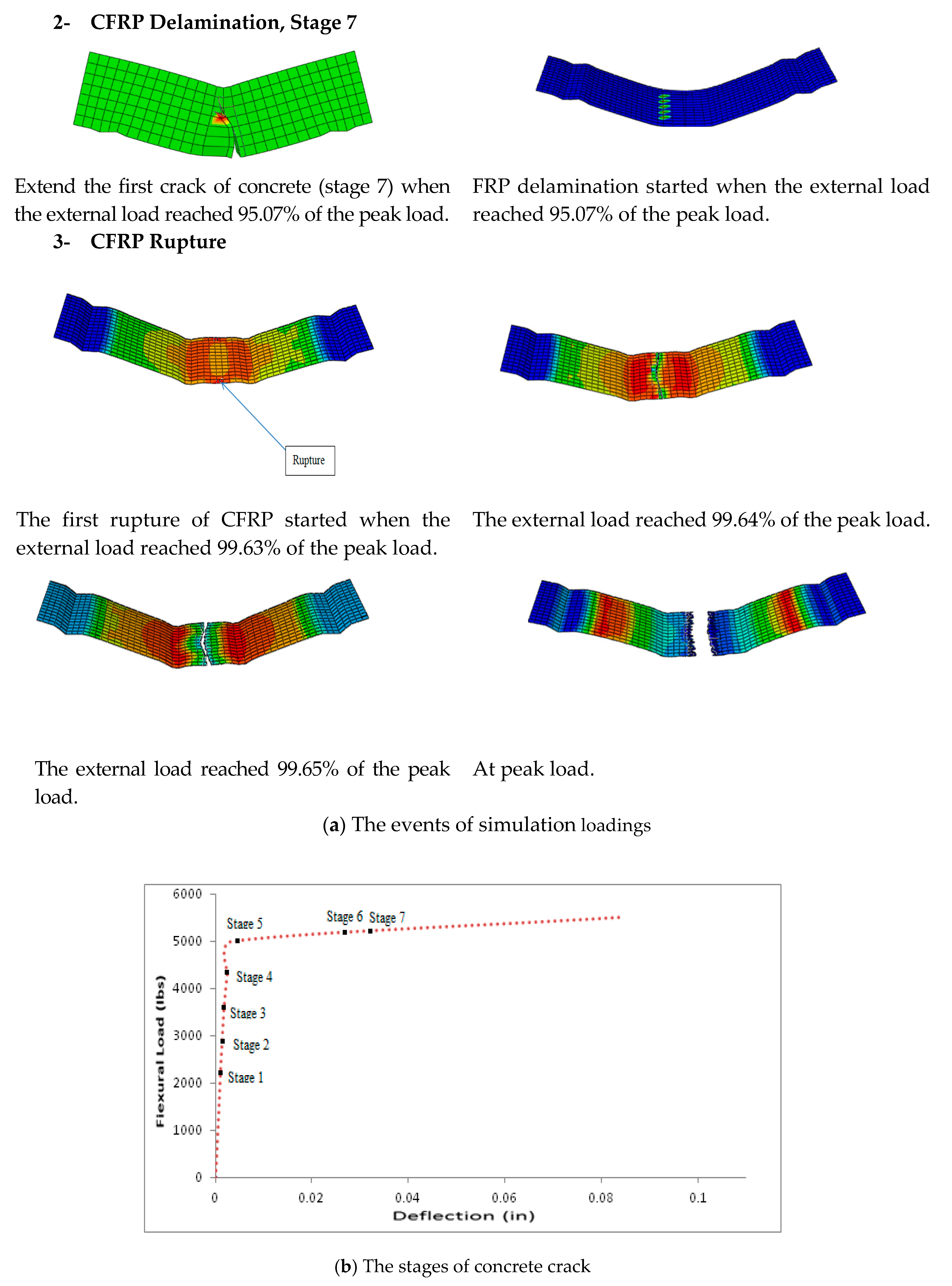
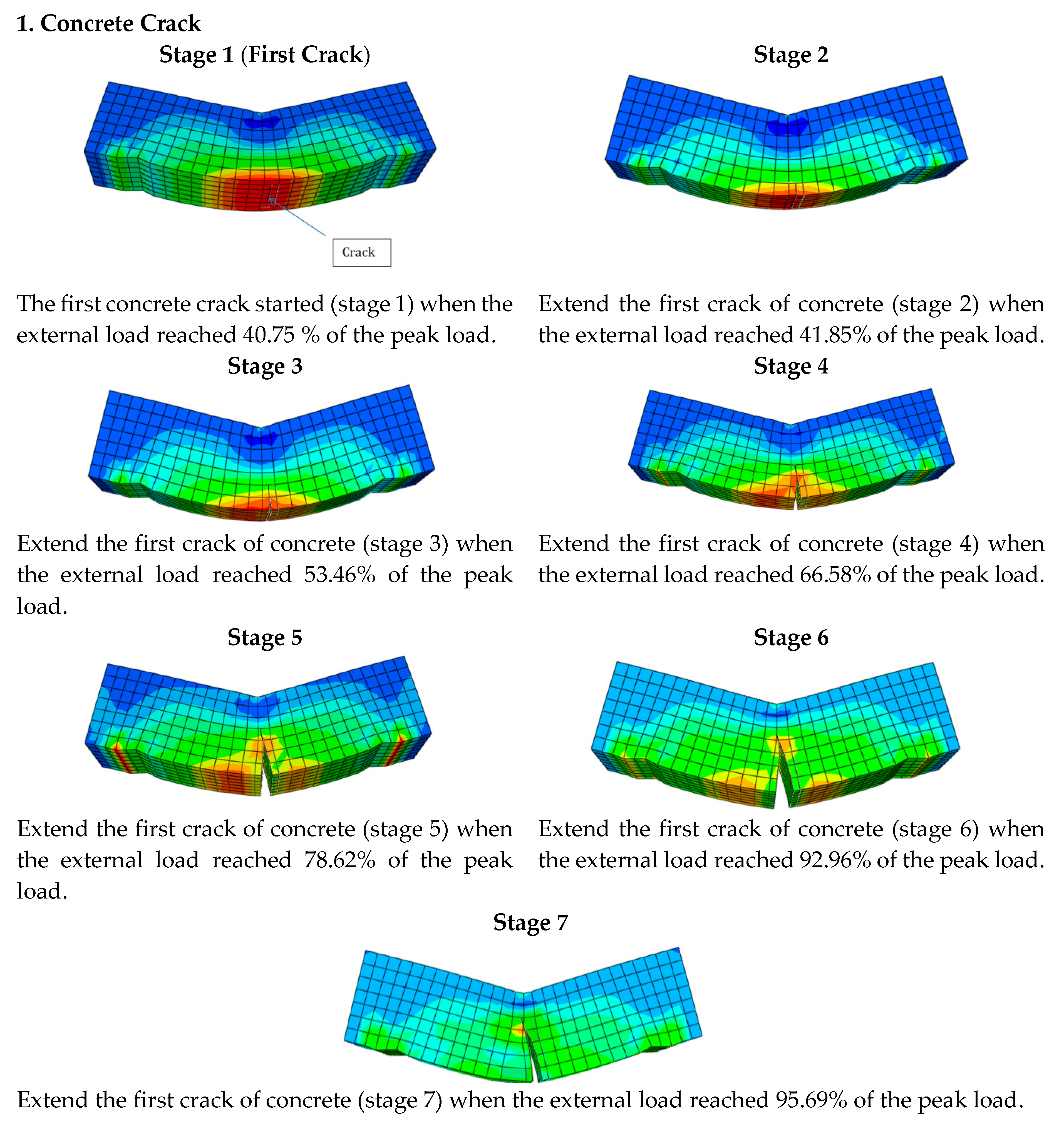
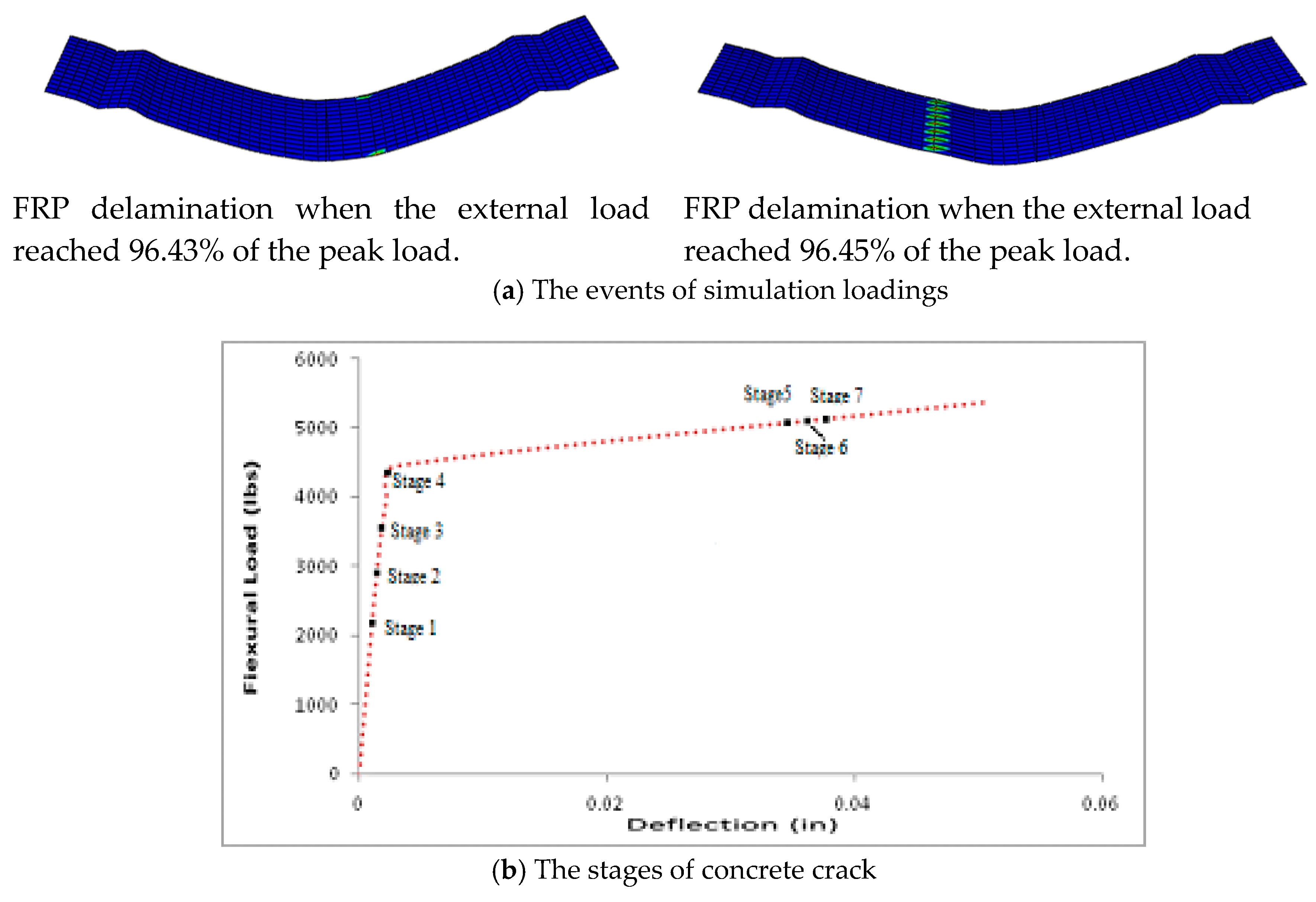
- At room temperature, the FRP strengthened beams showed predominately flexural cracks in concrete, followed by a brief FRP delamination prior to FRP rupture. The first rupture of FRP started when the external load reached 99.63% of the peak load.
- (3)
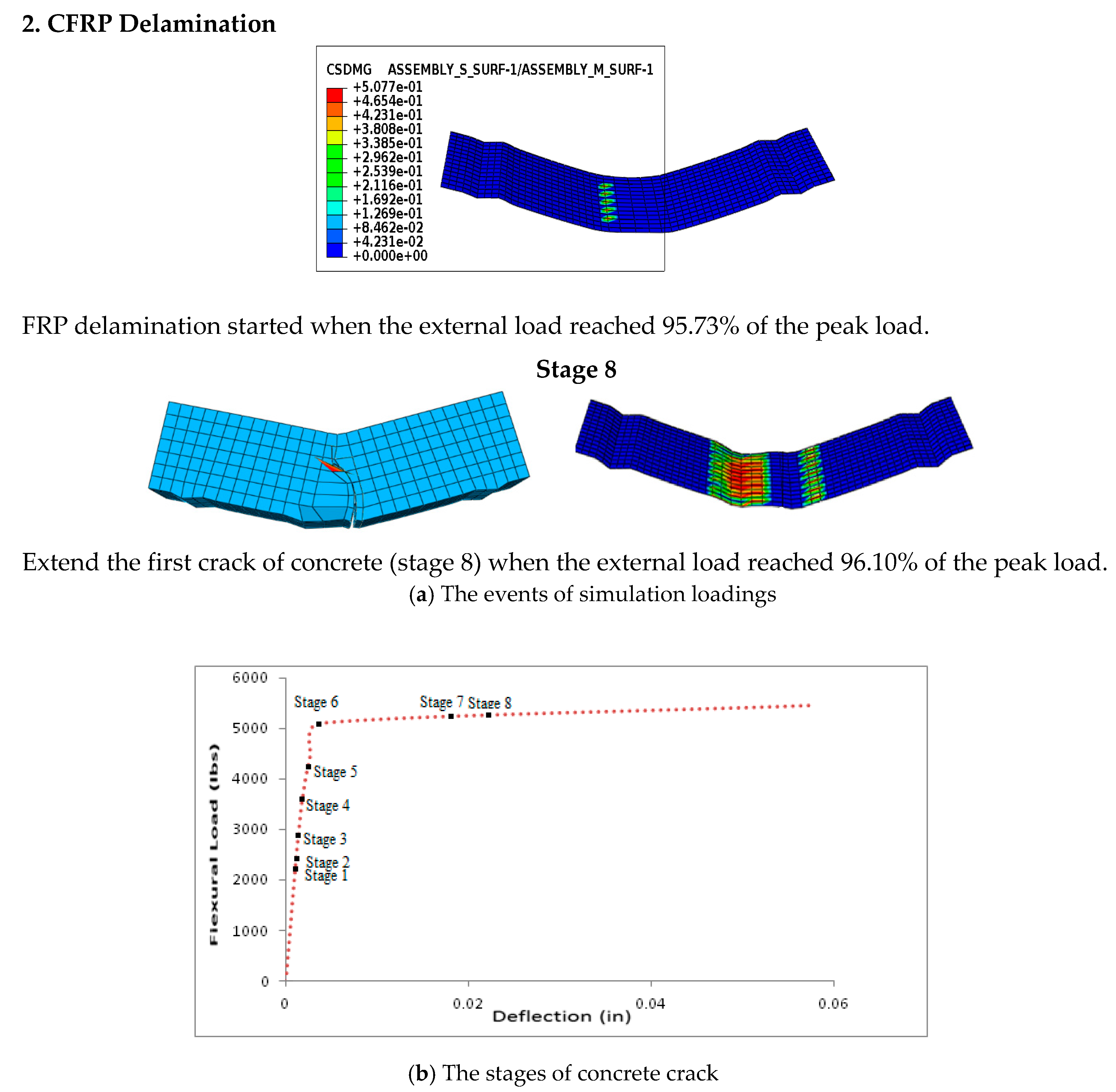
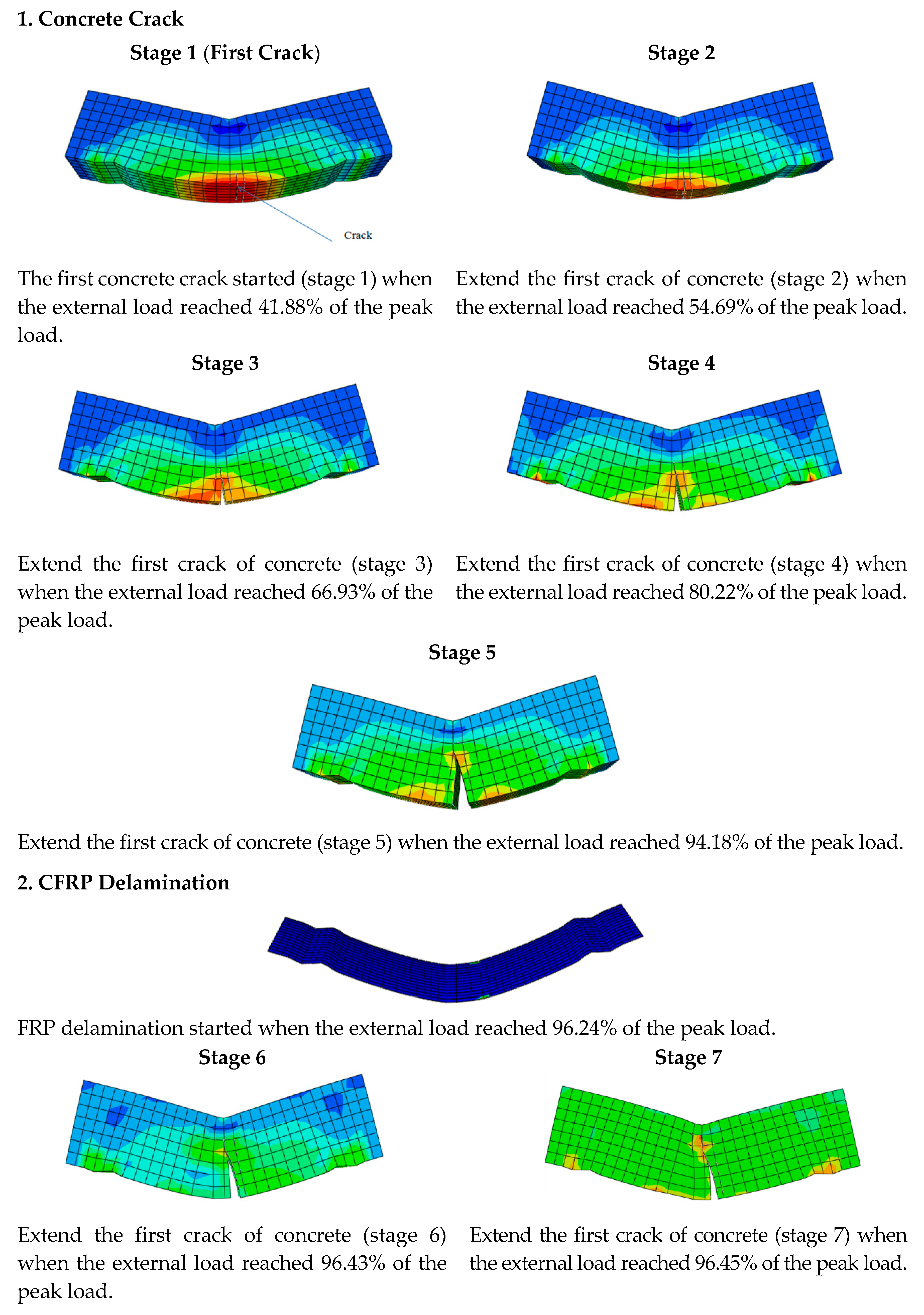
- When the temperature is raised to 100 °C and 180 °C, the FRP strengthened beams showed predominately flexural cracks in concrete, followed by a brief FRP delamination. As the temperature rises, a delay of FRP delamination has been observed.
- (a)
- The maximum flexural load of 100 °C decreased about 1% for the maximum flexural load of RT, these results suggest that the FRP strengthened concrete beams at 100 °C, flexural strength weaker than FRP strengthened concrete beams at RT.
- (b)
- The maximum flexural load of 180 °C decreased about 2% for the maximum flexural load of RT. These results suggest that the FRP strengthened concrete beams at 180 °C, flexural strength weaker than FRP strengthened concrete beams at RT and 100 °C.
- (c)
- This concludes that the flexural strength decreases with temperature rise for FRP strengthened concrete beams.
- (4)
- The FRP strengthened columns showed compression cracks in concrete and FRP rupture. The crack of FRP started at 96.94% of the peak load at room temperature. At the end of load (100% load), the crack of FRP occurred when the temperature is raised to 100 °C. While at 180 °C the crack of CFRP started at 97.48% of the peak load. The crack of FRP increased expansion at 180 °C than 100 °C, in the way of FRP rupture in the simulation was similar to the mode that was observed during the experimental tests.
- (a)
- The maximum compressive load of 100 °C increased about 27% for the maximum compressive load of RT. These results suggest that the FRP strengthened concrete columns at 100 °C, compressive strength stronger than FRP strengthened concrete columns at RT.
- (b)
- The maximum compressive load of 180 °C decreased about 39% for the maximum compressive load of RT. This is the same as the experimental results [2]. This concludes that the high temperature 180 °C has an adversely influence on the compressive strength of the specimens.
- (5)
- The thickness of FRP wrapping was 0.25 mm (0.01 in) in this study. I recommend in future, use thick of FRP wrapping more than 0.25 mm (0.01 in) for beams and columns to withstand high temperature (100 °C and 180 °C).(a) Also, it should be noted that the above mentioned findings are based on the cohesive behavior formulation (the cohesive traction–separation damage model) was use to the characterization of damage evaluation at the interface between concrete and FRP. In future, the virtual crack closure technique (VCCT) that is also available in the ABAQUS-CAE is recommended to be utilized and compared to the results obtained from the cohesive behavior formulation.
Author Contributions
Funding
Conflicts of Interest
References
- Banea, M.D.; da Silva, L.F.M. Adhesively Bonded Joints in Composite Materials: An overview. Available online: https://journals.sagepub.com/doi/pdf/10.1243/14644207JMDA219 (accessed on 28 January 2020).
- Elarbi, A. Durability Performance of FRP Strengthened Concrete Beams and Columns Exposed to Hydrothermal Environment. Ph.D. Dissertation, Wayne State University, Detroit, MI, USA, 2011. [Google Scholar]
- Elarbi, A.; Wu, H.-C. Flexural Behavior of Epoxy under Accelerated Hygrothermal Conditions. Fibers 2017, 5, 25. [Google Scholar] [CrossRef]
- Foster, S.K.; Bisby, L.A. Fire Survivability of External Bonded FRP Strengthening Systems. J. Compos. Constr. 2008, 12, 553–561. [Google Scholar] [CrossRef]
- Taljsten, B. FRP Strengthening of Existing Concrete Structures; Design Guidelines; Lulea University Printing Office: Lulea, Sweden, 2002. [Google Scholar]
- Park, S. Durability of Adhesive Joints Between Concrete and FRP Reinforcement in Aggressive Environments. Ph.D. Dissertation, The University of Texas at Austin, Austin, TX, USA, August 2005. [Google Scholar]
- Vpgel, H.; Svecova, D. Thermal Compatibility and Bond Strength of FRP Reinforcement in Prestressed Concrete Applications. J. Compos. Constr. 2007, 11, 459–468. [Google Scholar]
- Gheorghiu, C.; Labossiere, P.; Raiche, A. Environmental Fatigue Static Behavior of RC Beams with Carbon-Fiber-Reinforced Polymer. J. Compos. Constr. 2004, 8. [Google Scholar] [CrossRef]
- Bond of Reinforcement in Concrete; State-of-art Report, Federation International du béton; The International Federation for Structural Concrete: Lausanne, Switzerland, 2000; ISBN 2-88394-050-9.
- Fyfe Product Data Sheet: Tyfo_ S Saturant Epoxy, Fyfe Co. LLC. 2011. Available online: http://www.fyfeco.com/products/pdf/tyfosepoxy.pdf (accessed on 28 January 2020).
- Matthews, F.L.; Davies, G.A.O.; Hitchings, D.; Soutis, C. Finite Element Modeling of Composite Materials and Structures; Woodhead Publishing Ltd.: Sawston, UK, 2000. [Google Scholar]
- Moës, N.; Dolbow, J.; Belytschko, T. A Finite Element Method for Crack Growth without Remeshing. Inter. J. Numerical Methods Eng. 1999, 46, 131–150. [Google Scholar] [CrossRef]
- Extended Finite Element Method. Available online: http://en.wikipedia.org/wiki/Extended_finite_element_method (accessed on 28 January 2020).
- Di Tommaso, A.; Neubauer, U.; Pantuso, A.; Rostasy, F.S. Behavior of Adhesively Bonded Concrete-CFRP Joints at Low and High Temperatures. Mech. Compos. Mater. 2001, 37, 327–338. [Google Scholar] [CrossRef]
- Klamer, E.L.; Hordijk, D.A.; Kleinman, C.S. Debonding of CFRP Laminates Externally Bonded to Concrete Specimens at Low and High Temperatures. In Proceedings of the third International Conference on FRP Composites in Civil Engineering, Miami, FL, USA, 13–15 December 2006; pp. 35–38. [Google Scholar]
- Malvar, L.J.; Joshi, N.R.; Beran, J.A.; Novinson, T. Environmental Effects on The Short-Term Bond of Carbon Fiber-Reinforced Polymer CFRP Composites. J Compos. Constr. 2003, 7, 58–63. [Google Scholar] [CrossRef]
- Tadeu, A.J.B.; Branco, F.J.F.G. Shear Tests of Steel Plates Epoxy-Bonded to Concrete under Temperature. J. Mater. Civ. Eng. 2000, 12, 74–80. [Google Scholar] [CrossRef]
- Obaidat, Y.; Heyden, S.; Dahlblom, O. The Effect of CFRP and CFRP/Concrete Interface Models When Modelling Retrofitted RC Beams with FEM. Compos. Struct. 2010, 92, 1391–1398. [Google Scholar] [CrossRef]
- Mohammadi, T.; Wan, B.; Harries, K. Intermediate Crack Debonding Model of FRP Strengthened Concrete Beams Using XFEM. In Proceedings of the Simulia Community Conference, Vienna, Austria, 22 May 2013. [Google Scholar]
- Finite Element Analysis Lecture#3; Class Notes, Abaqus Software; Civil Engineering Department, Lawrence Technology University: Southfield, MI, USA, 2010.
- Michal, S.; Andrzej, W. Calibration of the CDP model parameters in Abaqus. In Proceedings of the World Congress on Advances in Structural Engineering and Mechanics (ASEM15), Incheon, Korea, 25–29 August 2015. [Google Scholar]
- Mikamia, C.; Wu, H.-C.; Elarbi, A. Effect of Hot Temperature on Pull-Off Strength of FRP Bonded Concrete. Constr. Build. Mater. 2015, 91, 180–186. [Google Scholar] [CrossRef]
- Dri, F.; Restrepo, D. Characterization of the Mode I Fracture Energy of Adhesive Joints; Course Materials CE 595—Project 2; Civil Engineering Department, Purdue University: West Lafayette, IN, USA, 2011. [Google Scholar]
- Finite Element Analysis Lecture#5; Class Notes, Abaqus Software; Civil Engineering Department, Lawrence Technology University: Southfield, MI, USA, 2010.
- Ezekiel, S.; Xiao, R.; Chin, C. Constitutive Model for Compressive Strength and Elastic Modulus for Concrete under Elevated Temperature. In Proceedings of the Structures Congress 2013: Bridging Your Passion with Your Profession, Pittsburgh, PL, USA, 2–4 May 2013; pp. 2916–2925. [Google Scholar]
- Guo, Z.; Shi, X. Experiment and Calculation of Reinforced Concrete at Elevated Temperatures; Elsevier Inc.: Amsterdam, The Netherlands, 2011. [Google Scholar]
- Venkatesh, K. Properties of Concrete at Elevated Temperatures; Michigan State University: East Lansing, MI, USA, 2014. [Google Scholar]
- Advanced Materials Epibond® 100 A/B High-Temperature Epoxy Structural Adhesive. Available online: http://www.huntsman.com/corporate/Media%20Library/a_MC4EE584E6EFA7273E040EBCD2C6B19E9/Innovation_MC4EE584E960B7273E040EBCD2C6B19E9/New%20HighPerformance_ME4D57E08A6F79FC2E040EBCD2B6B3510/files/Epibond%20100%20AB_US_e.pdf (accessed on 28 January 2020).





| The Parameter | The Value |
|---|---|
| Dilation angle [degrees] | 35 |
| Viscosity parameter | 0 |
| Eccentricity | 0.1 |
| fb0/fc0 | 1.16 |
| K | 0.67 |
| Typical Data | SikaWrap Hex 113C Carbon Fiber |
|---|---|
| Color | Black |
| Primary fiber direction | 0°/90° (bi-directional) |
| Weight per square yard | 196 g/m2 (5.7 oz) |
| Fiber Properties | |
| Tensile Strength | 3450 MPa (5 × 10⁵ psi) |
| Tensile Modulus | 230,000 MPa (33.4 × 10⁶ psi) |
| Elongation | 1.5% |
| Density | 1.8 g/cc (0.065 lbs./in3) |
| Normal Thickness | - |
| Cured Laminate Properties Design Values * | |
| Tensile Strength | 456 MPa (66,000 psi) |
| Tensile modulus | 41,400 MPa (6.0 × 10⁶ psi) |
| Elongation at breaks | 1.2% |
| Thickness | 0.25 mm (0.01 in) |
| The Property | The Value | |
|---|---|---|
| E: Young’s Modulus of adhesive | 17.24 GPa (2.5 × 10⁶ psi) Elarbi, 2011 [2] | |
| G: Shear Modulus of adhesive | 0.665 GPa (96,450.1 psi) Obaidat et al., 2010 [18] | |
| t: Thickness of adhesive | 0.1 mm (0.004 in) | Estimated |
| Stiffness Coefficients | Knn = E/t = 6.25 × 10⁸ Kss = G/t = 2.411 × 10⁷ Ktt = G/t = 2.411 × 10⁷ | |
| Cohesive Strength | 6 MPa (870.23 psi) Mikamia et al., 2015 [22] | |
| Shear Strength | 2.84 MPa (406.11 psi) | τmax = 1.46 Ga 0.165 fct 1.033 Obaidat et al., 2010 [18] = 1.46 (0.665 0.165) 2.03 1.033 fct is concrete tensile strength = 0.33 fc’=2.03 MPa |
| G: Fracture Energy | 91.8 g/mm (5.14 lb/in) (Estimated) | = (12 P2 a2) / (E h3 B3) Dri and Restrepo, 2011 [23] Where P is maximum experimental load, a corresponds to the precrack length, h is the height of the sample, and B is the width of the samples. |
| Young’s Modulus N/m2 | Poisson’s Ratio | Temperature (°C) |
|---|---|---|
| 3.49 × 10¹⁰ | 0.2 | 20 |
| 3.14 × 10¹⁰ | 0.2 | 200 |
| 2.79 × 10¹⁰ | 0.2 | 400 |
| The Property | The Value |
|---|---|
| E100 Young’s Modulus of concrete | 2.8 × 10⁴ MPa (4062000 psi) (Table 4) |
| No change in compressive strength (fc’) (Ezekiel, et al., 2013 [25]. Guo and Shi, 2011 [26]. Venkatesh, 2014 [27]) | 38 MPa (5502 psi) |
| No change in Max. Principal Stress (Ezekiel, et al., 2013 [25]. Guo and Shi, 2011 [26]. Venkatesh, 2014 [27]) | 2.45 MPa (355 psi) |
| The Property | The Value | |
|---|---|---|
| E100: Young’s Modulus of adhesive | 14.3 GPa (2.075 × 10⁶ psi) Elarbi, 2011 [2] | |
| G100: Shear Modulus of adhesive | 425.6 MPa (61728.05 psi) Advanced Materials Epibond® 100 A/B High-temperature Epoxy Structural Adhesive. Available online: [28] | |
| t: Thickness of adhesive | 0.1 mm (0.004 in) | Estimated |
| Stiffness Coefficients | Knn = E/t = 5.187 × 10⁸ Kss = G/t = 1.5432 × 10⁷ Ktt = G/t = 1.5432 × 10⁷ | |
| Cohesive Strength | 1.2 MPa (174.04 psi) Mikamia et al., 2015 [22] | |
| Shear Strength | 2.64 MPa (382.89 psi) | τmax = 1.46 Ga 0.165 fct 1.033 Obaidat et al., 2010 [18] = 1.46 (0.4256 0.165) 2.03 1.033 = 2.64 MPa (382.89 psi) |
| Fracture Energy (G) | 70.7 g/mm (3.96 lb/in) (Estimated) | = (12 P2 a2)/(E h3 B3) Dri and Restrepo, 2011 [23] Where P is maximum experimental load 100 °C, a is correspond to the precrack length 100 °C, h is the height of the samples, and B is the width of the sample. |
| The Property | The Value |
|---|---|
| E180 Young’s Modulus of concrete | 2.67 × 10⁴ MPa (3,873,000 psi) (Table 4) |
| No change in compressive strength (fc’) (Ezekiel, et al., 2013 [25]. Guo and Shi, 2011 [26]. Venkatesh, 2014 [27]) | 38 MPa (5502 psi) |
| No change in Max. Principal Stress (Ezekiel, et al., 2013 [25]. Guo and Shi, 2011 [26]. Venkatesh, 2014 [27]) | 2.45 MPa (355 psi) |
| The Property | The Value | |
|---|---|---|
| E180: Young’s Modulus of adhesive | 9825 MPa (1.425 × 10⁶ psi) Elarbi, 2011 [2] | |
| G180: Shear Modulus of adhesive | 219.4 MPa (31,828.52 psi) Advanced Materials Epibond® 100 A/B High-temperature Epoxy Structural Adhesive. Available online: [28] | |
| t: Thickness of adhesive | 0.1 mm (0.004 in) | Estimated |
| Stiffness Coefficients | Knn = E/t = 3.563 × 10⁸ Kss = G/t = 7.95713 × 10⁶ Ktt = G/t = 7.95713 × 10⁶ | |
| Cohesive Strength | 0.8 MPa (116.03 psi) Mikamia et al., 2015 [22] | |
| Shear Strength | 2.36 MPa (342.29 psi) | τmax = 1.46 Ga 0.165 fct 1.033 Obaidat et al., 2010 [18] = 1.46 (0.21945 0.165) 2.03 1.033 = 2.36 MPa (342.29 psi) |
| Fracture Energy (G) | 62.5 g/mm (3.5 lb/in) (Estimated) | = (12 P2 a2)/(E h3 B3) Dri and Restrepo, 2011 [23] Where P is maximum experimental load 180 °C, a is correspond to the precrack length 180 °C, h is the height of the samples, and B is the width of the sample. |
| Temp °C | Peak Load KN, (lbs) | First Rupture of FRP Beginning |
|---|---|---|
| RT | 24.52 KN, (5512.6 lbs) | 99.63% of the peak load |
| 100 °C | 24.29 KN, (5461 lbs) | no rupture |
| 180 °C | 23.91KN, (5375 lbs) | no rupture |
| Temp °C | Peak Load KN, (lbs) | First Rupture of FRP Beginning |
|---|---|---|
| RT | 387.54 KN, (87,122.65 lbs) | 96.94% of the peak load |
| 100 °C | 491.9 KN, (110,584.1 lbs) | at the peak load |
| 180 °C | 279.49 KN, (62,831.85 lbs) | 97.48% of the peak load |
© 2020 by the authors. Licensee MDPI, Basel, Switzerland. This article is an open access article distributed under the terms and conditions of the Creative Commons Attribution (CC BY) license (http://creativecommons.org/licenses/by/4.0/).
Share and Cite
Gawil, B.; Wu, H.-C.; Elarbi, A. Modeling the Behavior of CFRP Strengthened Concrete Beams and Columns at Different Temperatures. Fibers 2020, 8, 10. https://doi.org/10.3390/fib8020010
Gawil B, Wu H-C, Elarbi A. Modeling the Behavior of CFRP Strengthened Concrete Beams and Columns at Different Temperatures. Fibers. 2020; 8(2):10. https://doi.org/10.3390/fib8020010
Chicago/Turabian StyleGawil, Bassma, Hwai-Chung Wu, and Abulgasem Elarbi. 2020. "Modeling the Behavior of CFRP Strengthened Concrete Beams and Columns at Different Temperatures" Fibers 8, no. 2: 10. https://doi.org/10.3390/fib8020010
APA StyleGawil, B., Wu, H.-C., & Elarbi, A. (2020). Modeling the Behavior of CFRP Strengthened Concrete Beams and Columns at Different Temperatures. Fibers, 8(2), 10. https://doi.org/10.3390/fib8020010


