1. Introduction
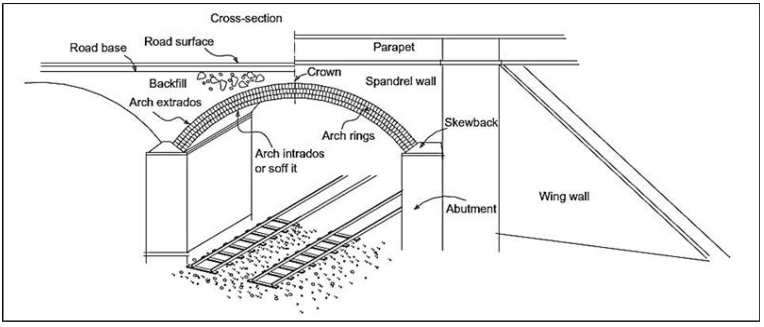
One of the oldest conventional bridge forms is the masonry arches bridges. They are robust, durable, and economical structures. Rocks and clay bricks were the earliest masonry materials utilized in arch construction over 4000 years. The masonry arches were historically constructed within walls of the buildings and utilized for ventilation and the allowance of lighting through. The technology of masonry arch construction within the years improved for achieving large spans [
1]. A straightforward identification of masonry arch bridge that which built from wedge-shaped blocks known as voussoirs and mortar. Furthermore, arches bridges are built on a temporary framework (commonly known as centering) as the masonry arch cannot stand alone until the placement of the last voussoir at the apex—the Keystone. Upon completion, the centering becomes removed, and the arching force (thrust force) starts to act at the abutments. The conventional masonry arch bridge was shown in
Figure 1.
The number of masonry arch bridges is almost one million worldwide. They are ancient, and many are carrying overestimated design loads, and they succeed to last hundreds of years. However, maintenance of masonry arches bridges still under consideration [
2]. In most cases, deterioration in masonry arch bridges is due to water flowing throughout the structure and plant growth as a result of water existence [
3]. Lack of maintenance of masonry heritage arches built from natural stone subjected to loading will lead to damage of the building stones at different levels [
4].
Rocks, stones, and clayey bricks are primary materials used in masonry construction, especially for bridges, and have been proven to have sufficient durability. Most arch bridges constructed from such materials are used for hundreds of years. Contrarily, so many bridges built from modern materials since the 20th century, like steel and reinforced concrete, require repair and strengthening after being in service for a relatively small part of their life span, and so are unable to meet the requirements of the current regulations [
5,
6].
Utilizing FRP composites in the strengthening of structures has gained particular attention and has been investigated in numerous experimental works [
7]. Several advantages can be gained from strengthening using FRP composites in repair as well as upgrading structures to carry extra loads. Moreover, low-weight, cost-effective, and high-strength/weight and modulus/weight ratios are achieved compared with some metallic materials [
8,
9]. Numerous experimental tests were performed on strengthened masonry structures as well as masonry arches, shells, and vaults that experimentally confirmed the efficiency of the strengthening system using FRP composites [
10,
11,
12].
From an economic perspective it is not feasible to use a traditional technique for masonry arch construction due to several reasons, like skilled labor cost for installing the framework and the manufacturing of voussoirs from natural stones. Therefore, it was a necessity for cost-effective bridges with the decline in traditional masonry arches that led to the development of FlexiArch bridges [
13].
Masonry arch bridges have proved their strength and durability over the years; in addition they have favorable aesthetics, which enhances the surroundings. Therefore, this insight brings us to develop a new form of masonry arch bridge after a downturn in the construction of such bridges for many years. An extensive experimental test program for the development of masonry arch bridges is illustrated in this article.
2. The Significance of the Present Investigation
The importance of the present research is to study the behavior of a new method for constructing masonry arch bridges. The self-form segmental concrete masonry arches system manufactured from plain concrete wedge-blocks and carbon fiber-reinforced polymer (CFRP) fabrics without any mortar and centering. Furthermore, we study the contribution of using an enlarged Keystone size on the load carrying capacity of the self-form segmental concrete masonry arches. Moreover, we investigate the effect of upgrading the self-form segmental concrete masonry arches bridges by CFRP fabrics in the local portion of the arch ring intrados. This study is also believed to assist in introducing a technique; one of its achievements is the featured speed of construction.
3. The Experimental Program
3.1. Description of Test Specimens
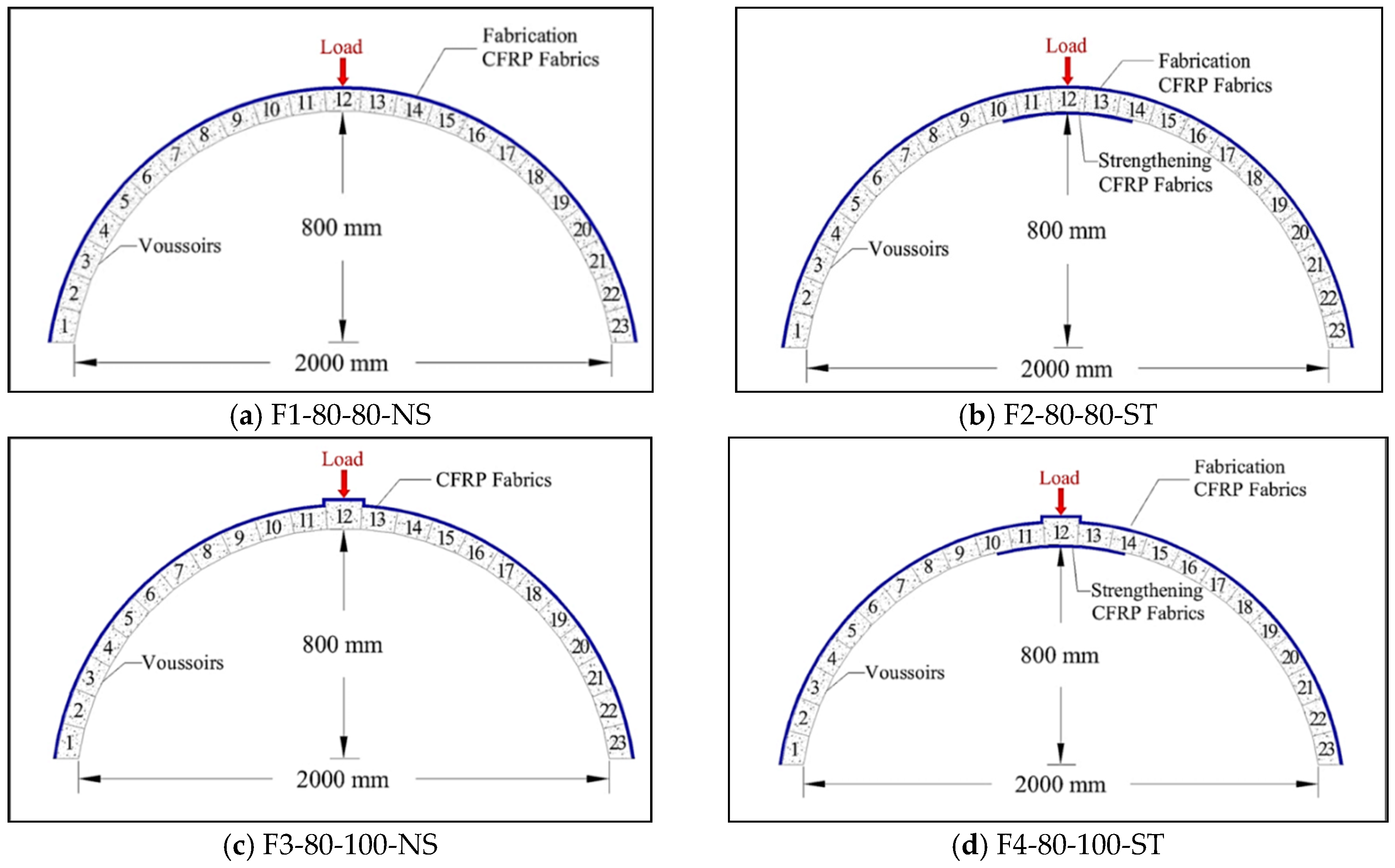
The test specimens comprised four experimental models of self-form segmental concrete masonry arches rings of 2 m span and 0.8 m rise.
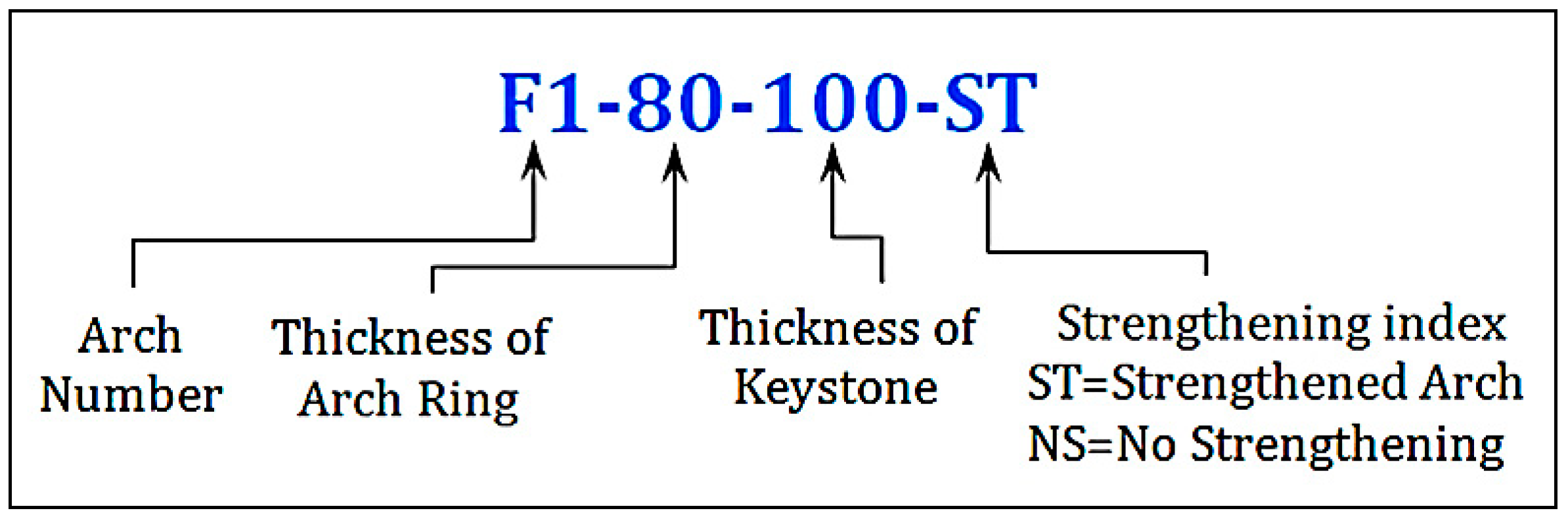
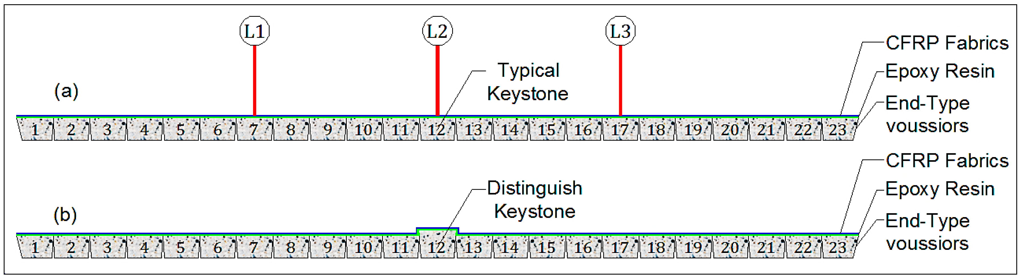
Figure 2 shows the arch designation system, which considers the arch ring number, thickness of the arch ring, thickness of the Keystone, and the strengthening index.
3.2. Materials
3.2.1. Concrete
The concrete used was designed according to the BS mix design method [
14,
15], for a specified compressive strength of 30 MPa at 28 days for standard cubes (150 × 150 × 150) mm
3. The concrete mix proportion is shown in
Table 1.
1. Fresh Concrete Test
To confirm the mix design, the slump test was performed for fresh concrete following ASTM C143-15a [
16]. The reported slump value for the fresh concrete was 90 mm.
2. Hardened Concrete Tests
Compressive strength, splitting tensile strength, and flexural strength tests were performed on standard concrete cubes, cylindrical, and prism specimens, respectively. These tests were conducted following international standards [
17,
18,
19]. Test results are shown in
Table 2.
3.2.2. Carbon Fiber-Reinforced Polymer (CFRP) Fabrics
Woven unidirectional CFRP fabrics from Al-Umara’ Bureau for Construction Chemicals, Baghdad, Iraq type SikaWrap-300C [
20] were used in the present study in the assemblage of the self-form segmental concrete masonry arches as well the strengthening process. The CFRP fabrics were adhered to the arch voussoirs using two-component, thixotropic epoxy-based impregnating resin and adhesive from Sika Group brand Sikadur-330 [
21]. Technical as well as mechanical properties of CFRP fabrics and the epoxy resin are shown in
Table 3.
3.3. Fabrication of Self-Form Segmental Concrete Masonry Arches
Four experimental models of self-form masonry arches of 2 m span and 0.8 m rise were fabricated, as shown in
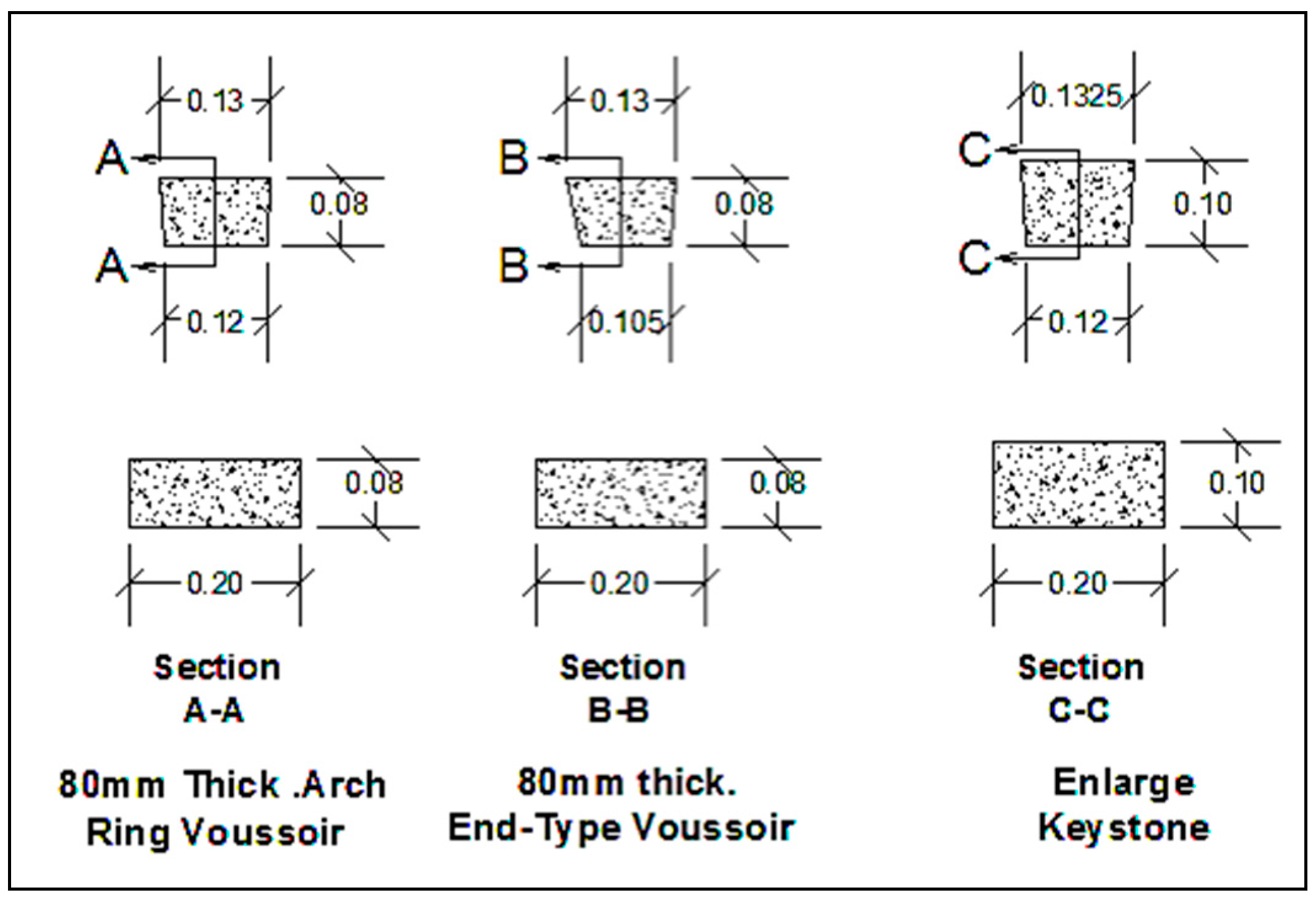
Figure 3. The geometry of the wedge-type voussoirs carefully calculated from the arch above ring dimensions for a segment of a circular arch profile. Each arch ring consisted of 23 wedge-shaped voussoirs; the end voussoirs were slightly different in dimensions for final arch ring installation purposes, as shown in
Figure 4.
Normal strength concrete with specifying compressive strength of 30 MPa at day 28 was designed for casting concrete voussoirs. Steel molds were fabricated very precisely for casting concrete voussoirs.
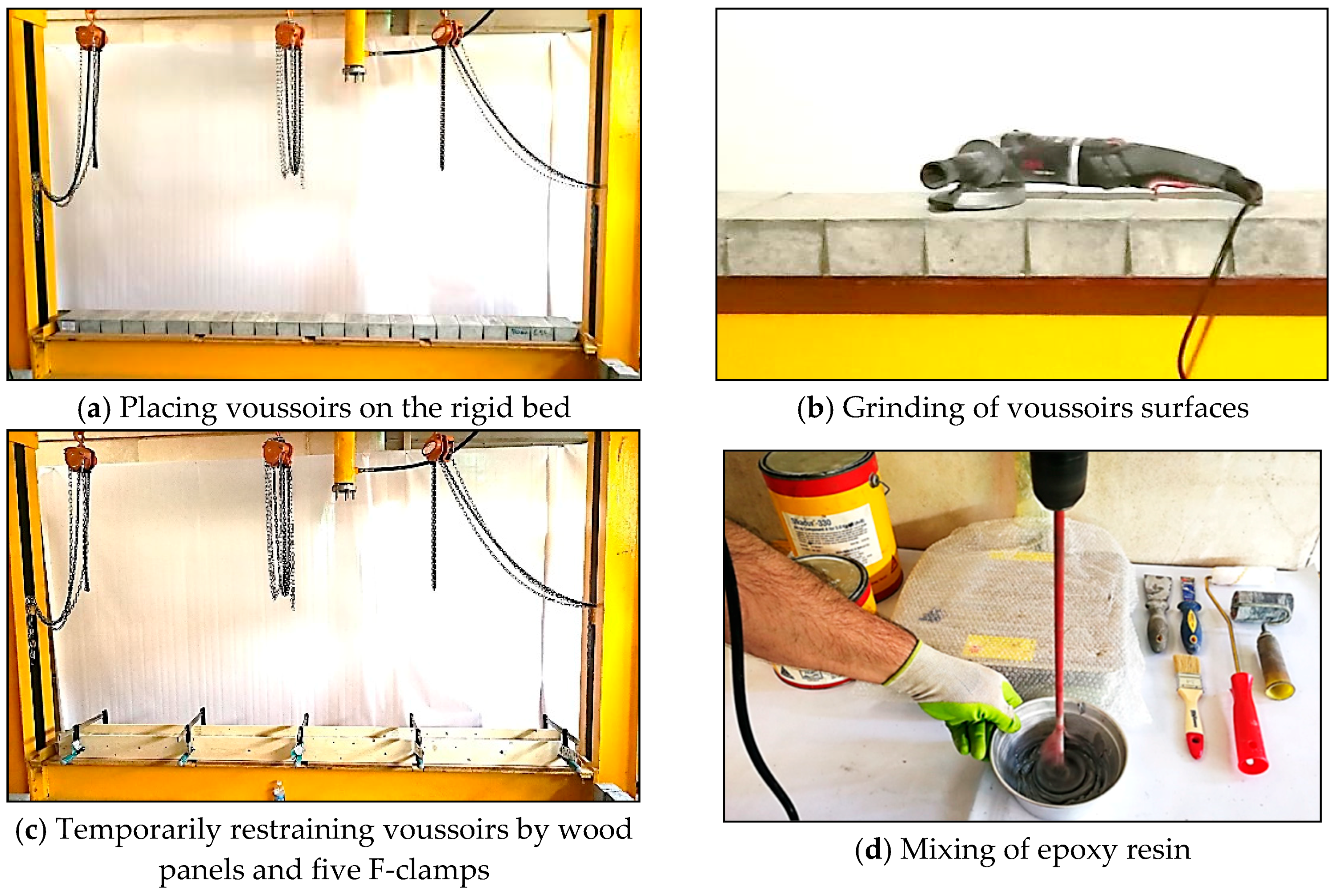
Upon completion of curing the wedge-shaped voussoirs, the fabrication stage of the self-form arch started as shown in
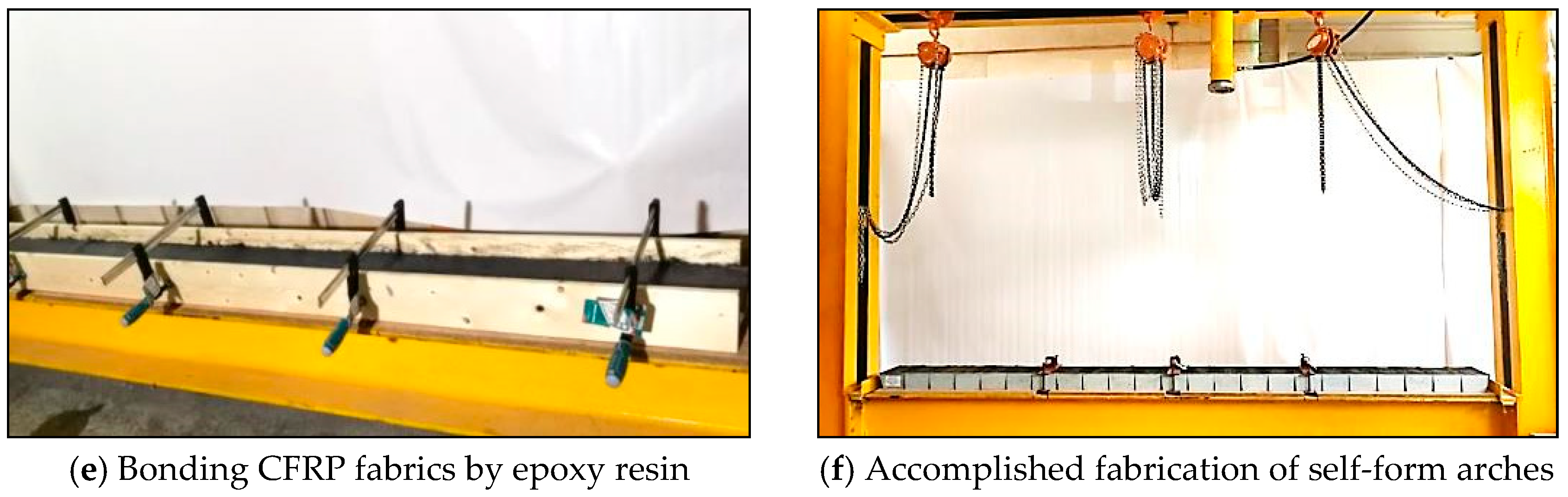
Figure 5. The voussoirs were laid contiguously on the flat rigid bed, and the surfaces of the voussoirs were grinded utilizing an electrical grinder. Furthermore, the voussoirs were restrained temporarily by thick two wood panels and five F-clamp distributed evenly. Soon after, the epoxy resin components were mixed mechanically and applied on the top surface of voussoirs. The fabrication accomplished by bonding one layer of CFRP fabrics (layer width 200 mm and length 3000 mm) on the epoxy coated area and left for curing.
Figure 6 illustrates the fabrication stages for the self-form segmental concrete masonry arch.
Self-form arches with thicker Keystone were fabricated in a similar manner. The distinguished thicker Keystone (100 mm thick.) was placed at the mid (instead of typical 80 mm thick voussoir V12) as shown in
Figure 6a. The process of fabrication of was done and the self-form arch was erected accordingly as shown in
Figure 6b.
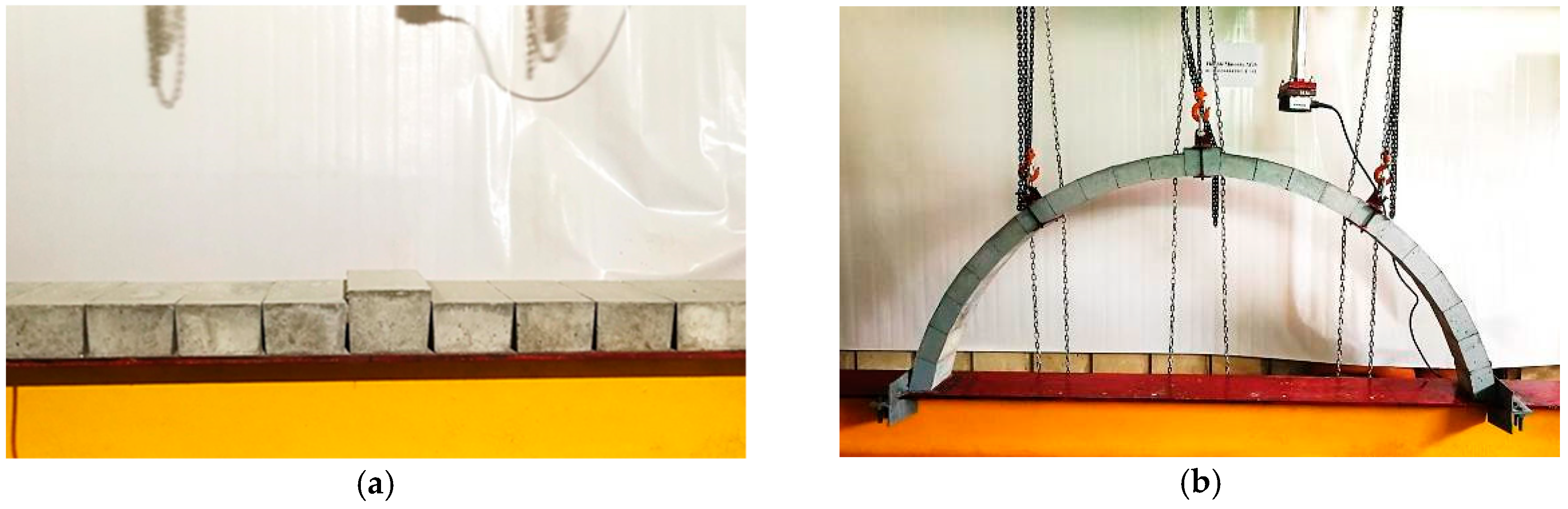
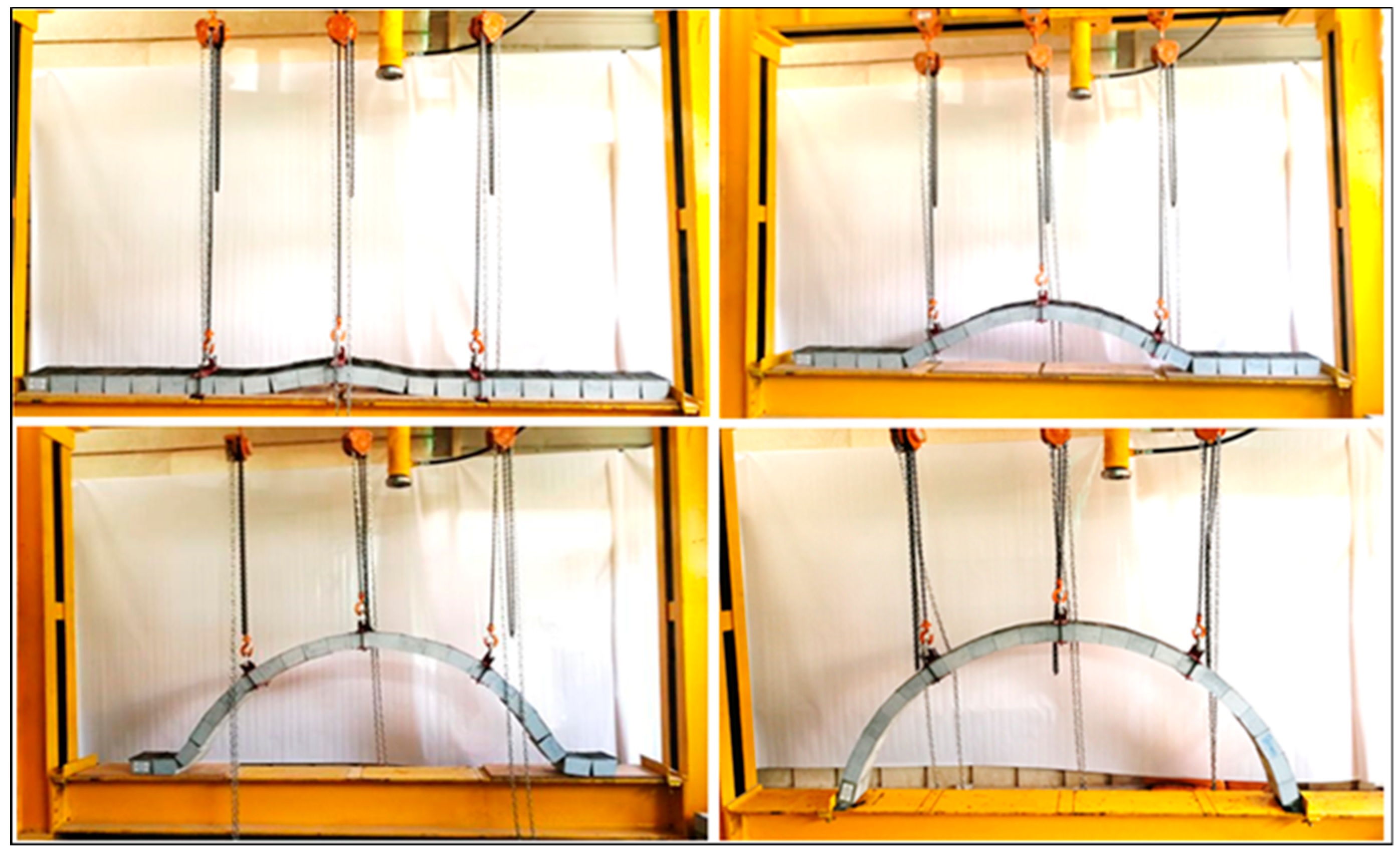
3.4. Lifting Self-Form Segmental Concrete Masonry Arches
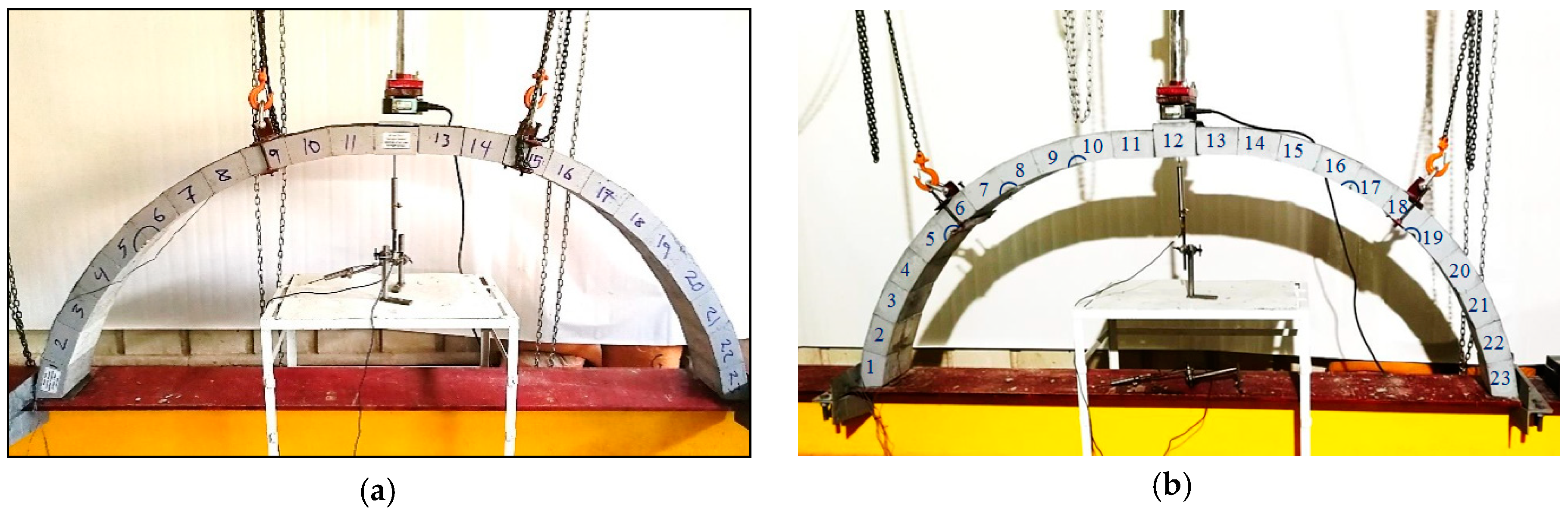
The self-form arch was initially fabricated on a rigid steel bed in a flat shape. Lifting of the self-form arch was done from three positions exactly on third-span, as shown in
Figure 7. The self-form arch was lifted, in the beginning, from the Keystone (L2), until the other two other lifting locations released from the resting bed. Lifting process continued simultaneously from three points, the wedge-shaped voussoirs will rotate, and the gap in-between closed. The self-form arch was formed, as a segment of a circle, upon completion of the lifting process as shown in
Figure 8.
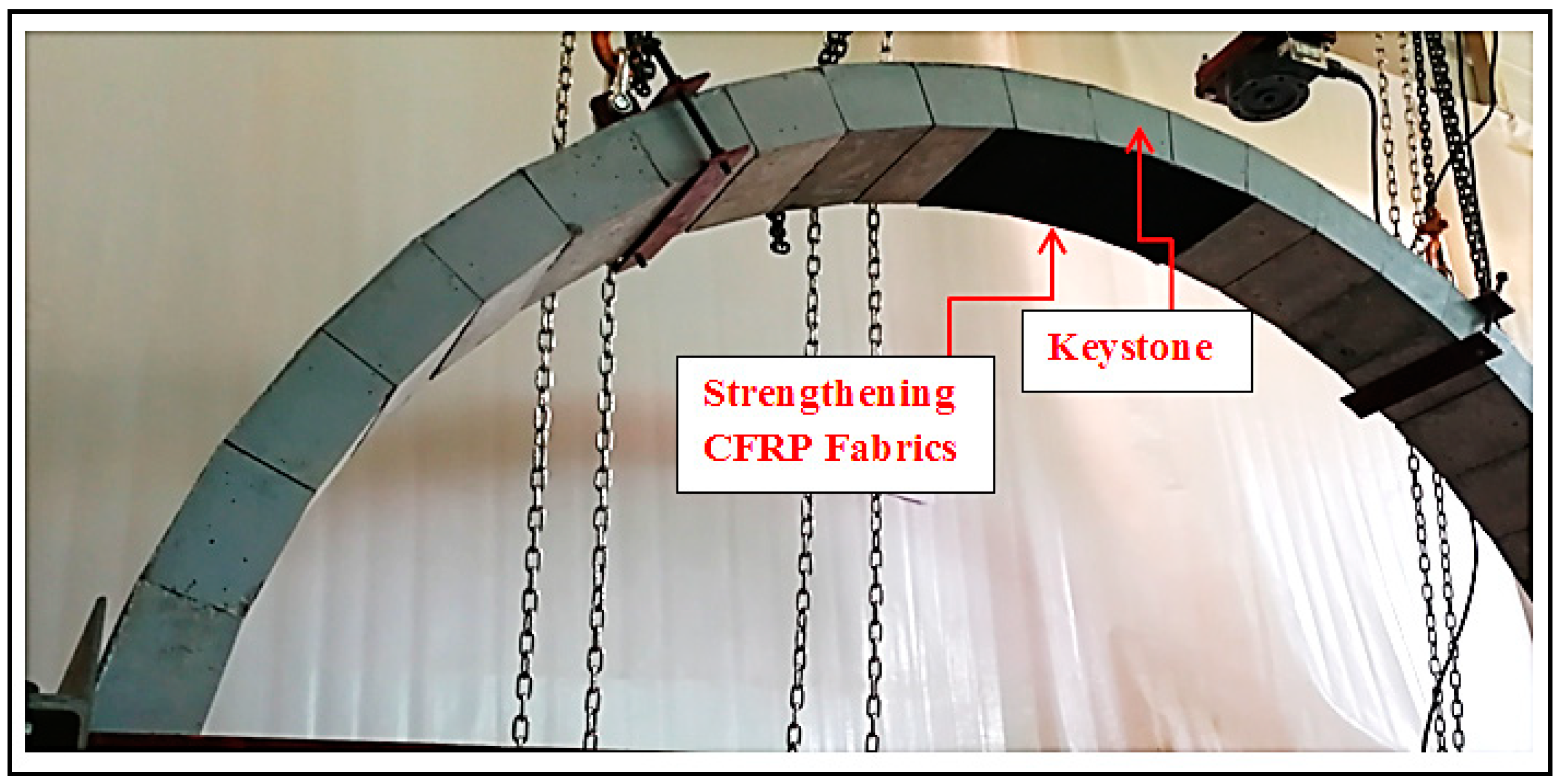
3.5. Strengthening of Self-Form Segmental Concrete Masonry Arches
Strengthening of the self-form masonry arches by CFRP textile was investigated in order to discover the contributions of CFRP composites on the load carrying capacity of the self-form masonry arches. After lifting, forming and installing the self-form masonry arch, the intrados of two sound arches were partially strengthened with one layer of CFRP fabrics with a width of 200 mm and a length of 450 mm. The strengthening layer was placed in the local region of the Keystone as shown in
Figure 9.
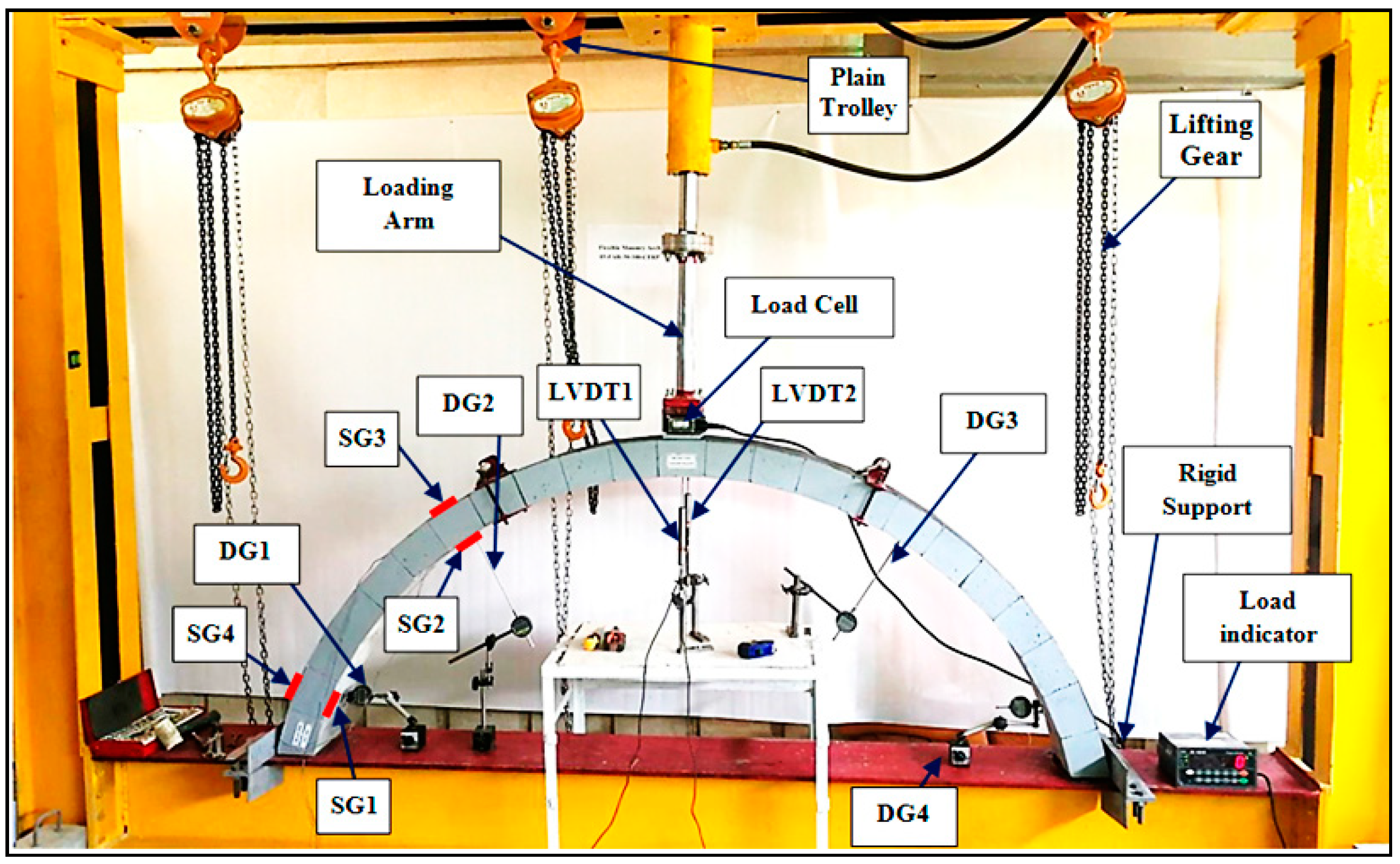
4. Instrumentation and Testing
Four self-form arches were fabricated. The arches rings were positioned in the loading frame and restrained against translation displacements in both horizontal and vertical directions. The load applied at the apex of the self-form arches on the keystone employing the hydraulic actuator as displayed in the schematic diagram of test setup
Figure 10. Four digital indicators were used to measure arch translations: two were used to measure outward horizontal displacement at the abutments, while two more were utilized to record the outward inclined translations at the third-spans. Furthermore, two precisely calibrated linear variable differential transducers (LVDTs) were also used for measuring the vertical displacements of the self-form masonry arches at the keystone.
Compressions, as well as tensile stains at both of the extrados and intrados of the arches, were also measured. Two types of single element wire strain gauges—PL-60-11-3L and BFLA-5—were used for recording strains in both concrete voussoirs and EBR-CFRP fabrics; respectively. Technical specifications, for both types of strain gauges, are described in
Table 4. Four strain gauges were located at the third span and near the supports. Two strain gauges were used for measurement tensile strains in EBR-CFRP fabrics, while the other two gauges used for measurements compression strain in concrete voussoirs. Data logger type CR-1000 from Campbell Scientific Inc. (Logan, UT, USA) used for recording the strains, loadings from the load cell, and the LVDT’s readings.
5. Results and Discussion
Four self-form segmental concrete masonry arches, as detailed in
Section 3.3, were tested under static loads considering the study of selected parameters. Two of those arches were upgraded by strengthening the intrados with CFRP fabrics in the limited mid-span region. Test results, as well as the contribution of strengthening by CFRP fabrics on the loading capacity of self-form masonry arches masonry arches, are summarized in
Table 5.
5.1. Observed Behavior and Failure Mode
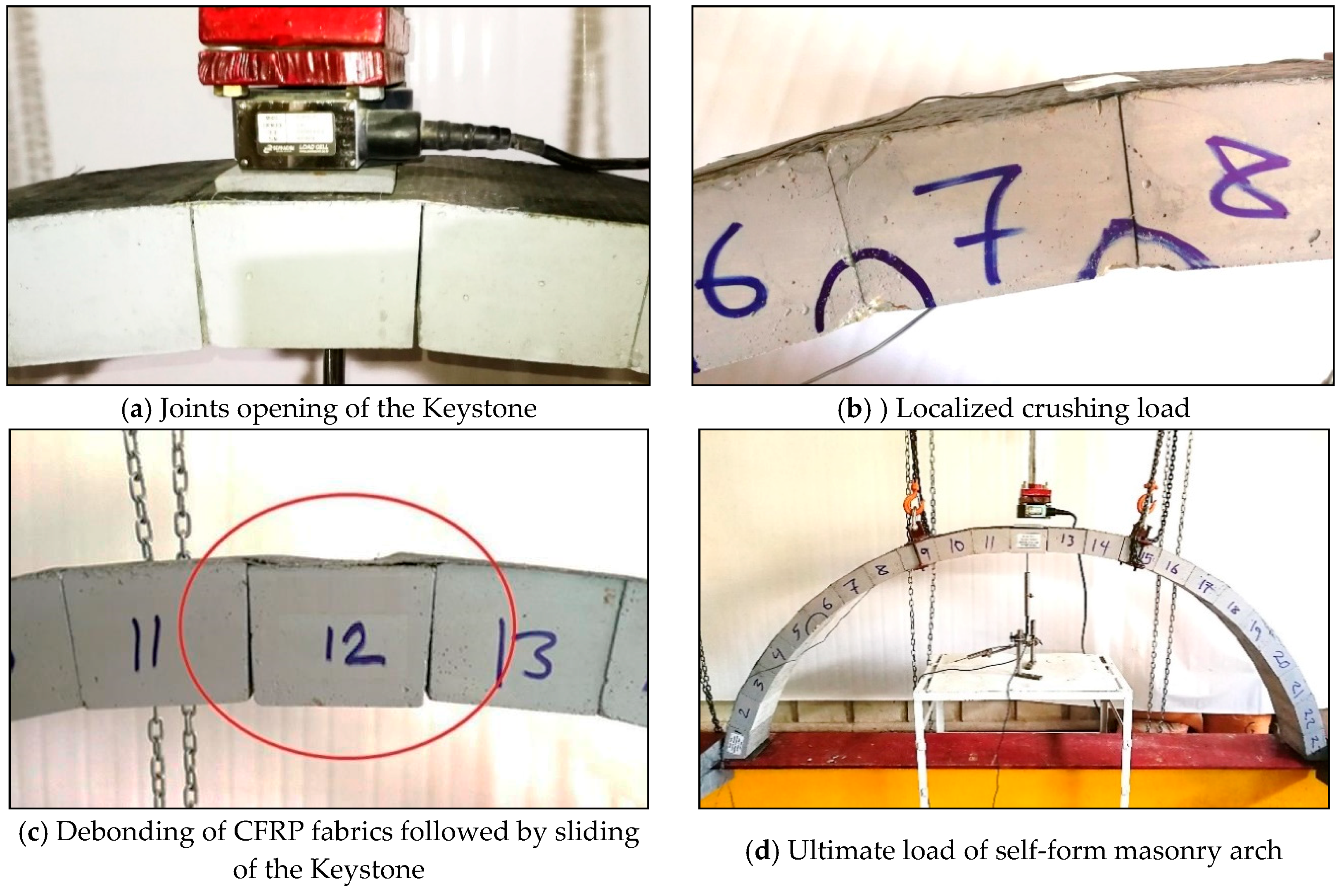
The behavior of self-form masonry arches under loading was monitored at different loading stages. Five distinguished loading stages were observed and considered as illustrated herein:
Load cause joints opening of the keystone, which occurs at an early stage of loading of self-form masonry arch ring. When the load applied on the keystone (V12), the joints V11-V12 and V12-V13 were opened accordingly.
Initial localized crushing load: most of the self-form masonry arch intrados (inner curve of the arch ring) under compression, except under the keystone. In accordance with, high stress concentration being on the corner of the wedge-shape concrete blocks which caused localized or partial crushing.
Debonding of CFRP fabrics load: this was recorded as a critical loading stage. The debonding of fabrication CFRP fabrics was specifically in the top surface of the Keystone, as a result, the keystone was released and freely to slide.
Voussoir initial sliding load: debonding of fabrication CFRP fabrics was followed by sliding of the Keystone. However, the friction forces as well as the thrust compression force tend to prevent Keystone sliding.
Ultimate loading: the loading that was recognized by progressive sliding of the keystone.
The behavior of the self-form masonry arches subjected to loading at the apex started with the opening of the joints of the Keystone voussoir V12. The joints V11-V12 and V12-V13 opened at an early loading stage followed by localized crushing of some voussoirs (in the corners) along the intrados of the arch ring with a further increment of the applied loading. This is due to the concentration of the compression stresses over a small part over the section of the voussoirs. Under further loading, partial Debonding of the fabrication CFRP fabrics observed along the keystone. Debonding of CFRP fabrics was followed by sliding of the keystone until it almost entirely released from the CFRP fabrics, and the arch ring tend to split out into two segments, which is considered the ultimate loading.
Figure 11 shows the loading stages of self-form masonry arches.
5.2. Displacements of Self-Form Masonry Arches at the Keystone
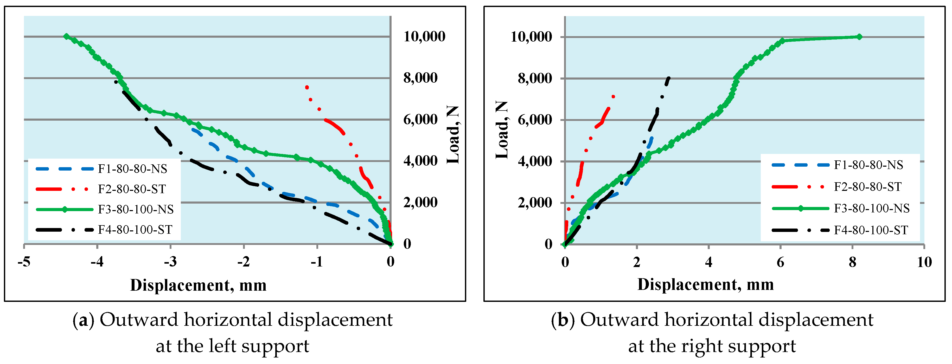
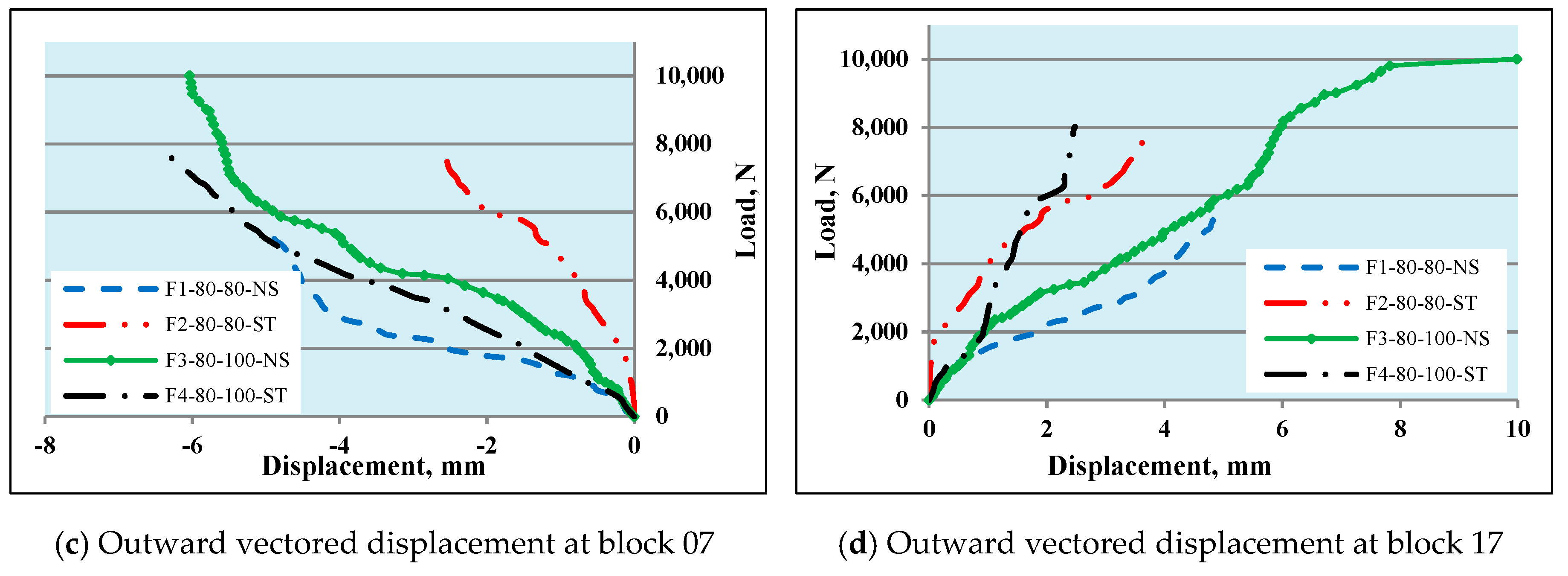
The tested specimens of self-form masonry arch rings have no mortar or backfilling, owing to that, the arch rings were not fully restrained against displacements when subjected to loading at any level except at support. Furthermore, the behaviors of self-form masonry arches were almost similar to traditional arches when loaded at the keystone. The apex voussoir deflected downward, yet both of the quarter-to-third and support segments of the arch ring were displaced outward. However, the existence of CFRP fabrics in the extrados tends to limit or prevent arch displacement. Upgrading of self-form masonry arches by CFRP even at the local region in the intrados reduced those displacements.
Figure 12 shows the load–displacement behavior of the self-form masonry arches at the keystone. A considerable increase in the load carrying capacity of the self-form arch F3-80-100-NS with 25% thicker keystone compared to the self-form masonry arch F1-80-80-NS was 79%, although the displacements for both arches was almost the same at ultimate loading. This behavior was due to the contribution of the used thicker keystone in resisting the loads that cause debonding, sliding and crushing as well as the ultimate loading. The outward displacement of the arch specimens at the third span as well as the supports were shown in
Figure 13. It is clear that the arch F3-80-100-NS displaced much more than the arch F1-80-80-NS by 20–226%. This behavior was probably due to the thicker keystone of the former arch ring, where the keystone prevented from sliding due to its large dimension in addition to the high thrust force until loading reached twice the load that causes sliding of the keystone of arch F1-80-80-NS.
5.3. Strains in the Self-Form Segmental Concrete Masonry Arches
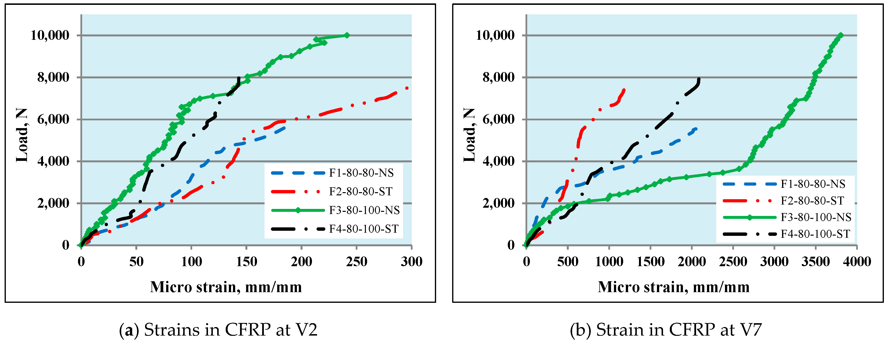
Load vs. compression strain in the concrete voussoirs V2 and V7 in the intrados of the tested self-form masonry arches is shown in
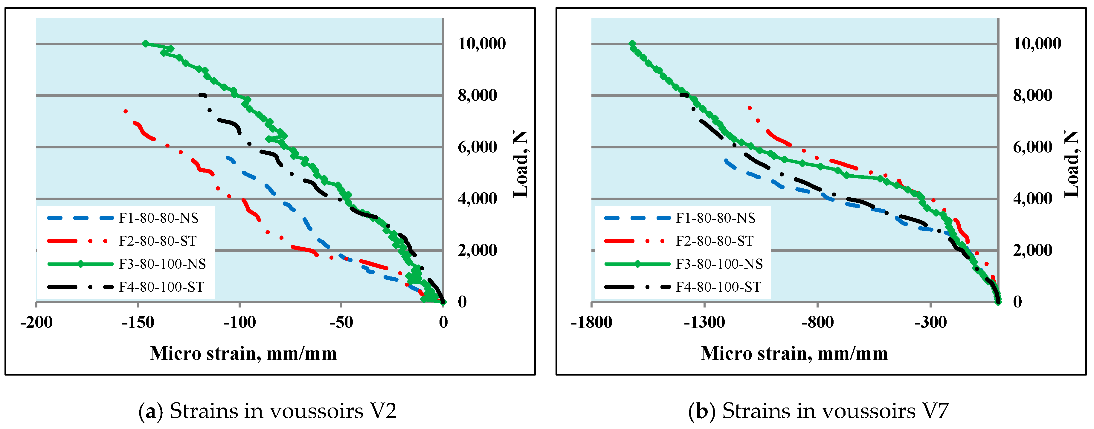
Figure 14. As aforementioned, arch F3-80-100-NS sustained higher ultimate load than arch F1-80-80-NS by 79%. Moreover, the compression strain developed in voussoirs V2 and V7 of arch F3-80-100-NS were 38% and 29%, respectively, than that developed in arch F1-80-80-NS. The increment in strains was probably due to the effect of using thicker as well as broader keystone in arch F3-80-100-NS, which produces higher localized thrust forces and hence higher compression strain.
Figure 15 shows the load vs. tensile strain generated in the fabrication CFRP sheets read by the strain gauges adhered on the extrados of the self-form masonry arch ring at voussoirs V2 and V7. The tensile strain developed in voussoirs V2 and V7 of arch F3-80-100-NS were 31% and 81% than arch F1-80-80-NS, respectively. The resulted in higher strain in arch F3-80-100-NS, which was expected as the thrust force developed in arch F3-80-100-NS was almost twice than that in arch F1-80-80-NS. Furthermore, the thrust force was probably being tangent or close to the intrados of arch F3-80-100-NS at V7 which produces higher tensile stress in limited depth of voussoir V7 which was carried mostly by CFRP fabrics and hence producer higher tensile strain.
5.4. Contribution of Strengthening CFRP Fabrics
Strengthening of the self-form masonry arches was done partially and limited to the mid-loading zone. Considering arches F1-80-80-NS and F2-80-80-ST, which are typical except the later, were strengthened by CFRP fabrics as shown previously in
Figure 3b. The strengthening enhanced the load carrying capacity of arch F2-80-80-ST by 35% and considerably reduced the vertical displacement at the keystone by 70% concerning arch F1-80-80-NS. The failure mode of a strengthened arch was different, and joint opening, as well as sliding of the Keystone, was prevented by the strengthening CFRP fabrics from sliding. Moreover, the strengthening CFRP fabrics limited the thrust force within the middle of the depth of the arch ring and hence prevented the generation of localized stresses as well as the crushing of the voussoirs. Furthermore, partial strengthening by CFRP fabrics for voussoirs V11 to V13 makes these mid-three voussoirs behave as a rigid segment and slide over the unstrengthened closest voussoir V15, as shown in
Figure 16c.
Relating to self-form masonry arches F3-80-100-NS and F4-80-100-ST, both of those arches have distinguished thicker Keystone, and the same arch barrel except the later was strengthened by CFRP fabrics as shown in
Figure 3d. Despite the strengthening considerably decreased the vertical displacement of the arch F4-80-100-ST at the keystone by 52%, the load carrying capacity was reduced by 19% compared to arch F3-80-100-NS. This behavior due to the existence of partial strengthening of arch ring intrados from voussoirs V11 to V13 prevented the sliding of V12. Additionally, partial strengthening CFRP fabrics make these mid-three voussoirs behave as a rigid segment and slide over the least thickness of the ring (without strengthening) over the closest voussoir V14. Also, debonding of fabrication CFRP fabric and sliding of voussoir V14 over V15 was an additional reason, as shown in
Figure 16d.
6. Conclusions
An experimental program comprised of four self-form segmental concrete masonry arches with a span of 2 m and a rise of 0.8 m was conducted to introduce the behavior of novel method for fabrication masonry arches without any formwork as well as voussoirs binding mortar. The parametric study focused on the effect of using distinguished thicker keystone by 25% among the typical arch ring voussoirs and the contribution of partial strengthening the intrados of the arch ring by CFRP fabrics in order to investigate the load carrying capacity of the self-form arches. Based on the results obtained from the experimental program, the following conclusions are presented.
The self-form segmental concrete masonry arches are easy to fabricate, consisted of precise precast concrete voussoirs, and could install without the need of any construction framework.
The use of a thicker keystone altered the behavior of the self-form masonry arch as well as considerably increased the load carrying capacity and reduced the vertical displacements. Furthermore, the existence of a thicker keystone in self-form masonry arch F3-80-100-NS delayed the joints opening to loading more than 5 times the load that causes the joint opening of self-form masonry arch F1-80-80-NS.
The upgrading of self-form arch F2-80-80-ST, which not used thicker keystone, by the partial strengthening of the intrados with CFRP fabrics was found effective. A considerable increase in the debonding load of fabrication CFRP fabrics by 81%, increase the localized crushing load by 13%, considerably increase voussoir sliding load by 107% as well as the ultimate load carrying capacity of the self-form masonry arch by 79% compared with unstrengthened arch F1-80-80-NS.
The upgrading of distinguished thicker Keystone self-form arch F4-80-100-NS by the partial strengthening of the intrados with CFRP fabrics alter the behavior and was found useful at an earlier stages of loading. The strengthening of the intrados considerably increases the localized crushing load by 80%. However, a decrease in all other loading stages was found by 7, 11, and 19% for CFRP fabrics debonding load, voussoir sliding load, and ultimate load, respectively, in relation to unstrengthened arch F3-80-100-NS.
7. Area of Future Studies
To summarize the recommendations for future work, the following points are highlighted.
Investigation of the behavior of self-form masonry arches with backfilling.
Formulating numerical model for analyzing self-form masonry arches.
Studying the effectiveness of variable self-form masonry arches barrel thickness on the load carrying capacity.
Considering more grades of concrete and discover the localized crushing stresses, if they exist.
Author Contributions
Conceptualization, A.A.A. and A.I.S.; methodology, A.A.A. and A.I.S.; validation, A.A.A. and A.I.S.; investigation, A.A.A.; resources, A.A.A.; data curation, A.A.A.; writing—original draft preparation, A.A.A.; writing—review and editing, A.A.A.; visualization, A.A.A. and A.I.S.; supervision, A.I.S.
Funding
This research received no external funding.
Acknowledgments
The authors would like to thank University of Baghdad/College of Engineering/Civil Engineering Departments for support.
Conflicts of Interest
The authors declare no conflict of interest.
References
- Boothby, T.E.; Anderson, A.K., Jr. The masonry arch reconsidered. J. Archit. Eng. 1995, 1, 25–36. [Google Scholar] [CrossRef]
- Melbourne, C.; Wang, J.; Tomor, A.K. A new masonry arch bridge assessment strategy (SMART). Proc. Inst. Civ. Eng. Bridge Eng. 2007, 160, 81–88. [Google Scholar] [CrossRef]
- Harvey, B. Stiffness and Damage in Masonry Bridges. Proc. Inst. Civ. Eng. Bridge Eng. 2012, 165, 127–134. [Google Scholar] [CrossRef]
- Grandjean, A.; Brühwiler, E. Load-bearing capacity of masonry arch bridges using a plastic model. In Proceedings of the Protection of Historical Buildings, PROHITECH 09, Rome, Italy, 21–24 June 2009; Taylor & Francis Group: London, UK, 2009. [Google Scholar]
- Gupta, A.; Taylor, S.; Long, A.; Kirkpatrick, J.; Hogg, I. A Flexible Concrete Arch System for Durable Bridges. IABSE Symp. Rep. 2006, 92, 34–40. [Google Scholar] [CrossRef]
- The Highway Agency. BD 91/04 Unreinforced Masonry Arch Bridges. In Design Manual for Roads and Bridges; Overseeing Organizations of England: England, UK, 2004; Volume 2. [Google Scholar]
- Bati, S.B.; Rovero, L.; Tonietti, U. Strengthening Masonry Arches with Composite Materials. J. Compos. Constr. 2007, 11, 33–41. [Google Scholar] [CrossRef]
- Abdulhameed, A.A.; Said, A.I. Behaviour of Segmental Concrete Beams Reinforced by Pultruded CFRP Plates: An Experimental Study. Eng. J. accepted.
- Abdulhameed, A.A.; Said, A.I. Evaluation of Wedge-Block Concrete Beams Reinforced with EBR-CFRP Laminates by Modified ACI 440.2R-2017 Guide. Fibers. under review.
- Bertolesi, E.; Milani, G.; Carozzi, F.G.; Poggi, C. Ancient masonry arches and vaults strengthened with TRM, SRG and FRP composites: Numerical analyses. Compos. Struct. 2018, 187, 385–402. [Google Scholar] [CrossRef]
- Foraboschi, P. Strengthening of masonry arches with fiber-reinforced polymer strips. J. Compos. Constr. 2004, 8, 191–202. [Google Scholar] [CrossRef]
- Oliveira, D.V.; Basilio, I.; Lourenço, P.B. Experimental behavior of FRP strengthened masonry arches. J. Compos. Const. 2010, 14, 312–322. [Google Scholar] [CrossRef]
- Taylor, S.; Long, A.; Robinson, D.; RANKIN, B.; Gupta, A.; Kirkpatrick, J.; Hogg, I. Development of a flexible concrete arch. Concrete 2007, 41, 34–37. [Google Scholar]
- British Standards Institution. BS EN 206 Concrete-Specifications, Performance, Production, and Conformity; British Standards Institution: London, UK, 2013. [Google Scholar]
- British Standards Institution. BS EN 8500–1 Concrete—Complementary British Standard to BS EN 206 Part 1: Method of Specifying and Guidance for the Specifier; British Standards Institution: London, UK, 2015. [Google Scholar]
- American Society for Testing and Materials. ASTM C143–15 Standard Test Method for Slump of Hydraulic-Cement Concrete; American Society for Testing and Materials: West Conshohocken, PA, USA, 2010. [Google Scholar]
- British Standards Institution. BS EN 12390–3, Testing Hardened Concrete Part 3: Compressive Strength of Test Specimens; British Standards Institution: London, UK, 2011. [Google Scholar]
- American Society for Testing and Materials. ASTM C496/496M-17, Standard Test Method for Splitting Tensile Strength of Cylindrical Concrete Specimens; American Society for Testing and Materials: West Conshohocken, PA, USA, 2011. [Google Scholar]
- American Society for Testing and Materials. ASTM C78–15a, Standard Test Method for Flexural Strength of Concrete (Using Simple Beam with Third-Point Loading); American Society for Testing and Materials: West Conshohocken, PA, USA, 2015. [Google Scholar]
- Sika Group. Available online: https://gcc.sika.com/dms/getdocument.get/70591f44-767e-358f-87e3-939e29b4a180/2_SikaWrap-300%20C_PDS_GCC__(05-2017)_1_1.pdf (accessed on 22 June 2019).
- Sika Group. Available online: https://gbr.sika.com/dms/getdocument.get/2314dd46-952c-391a-bf18-53262c7e1277/Sikadur%20330%20PDS.pdf (accessed on 22 June 2019).
Figure 1.
Conventional masonry arch bridge.
Figure 1.
Conventional masonry arch bridge.
Figure 2.
Designation system for self-form segmental concrete masonry arches.
Figure 2.
Designation system for self-form segmental concrete masonry arches.
Figure 3.
Experimental models of self-form segmental concrete masonry arches.
Figure 3.
Experimental models of self-form segmental concrete masonry arches.
Figure 4.
Wedge-shape voussoirs geometry.
Figure 4.
Wedge-shape voussoirs geometry.
Figure 5.
Fabrication of self-form segmental concrete masonry arches.
Figure 5.
Fabrication of self-form segmental concrete masonry arches.
Figure 6.
Placing voussoirs on the rigid bed (a), erecting self-form arch with thicker Keystone (b).
Figure 6.
Placing voussoirs on the rigid bed (a), erecting self-form arch with thicker Keystone (b).
Figure 7.
The self-form arch ready for forming, typical Keystone arch (a), distinguish Keystone arch (b).
Figure 7.
The self-form arch ready for forming, typical Keystone arch (a), distinguish Keystone arch (b).
Figure 8.
Formation of self-form segmental concrete masonry arches.
Figure 8.
Formation of self-form segmental concrete masonry arches.
Figure 9.
Strengthened self-form masonry arch F2-80-80-ST.
Figure 9.
Strengthened self-form masonry arch F2-80-80-ST.
Figure 10.
Test setup of self-form segmental concrete masonry arches.
Figure 10.
Test setup of self-form segmental concrete masonry arches.
Figure 11.
Loading stages of self-form segmental concrete masonry arches.
Figure 11.
Loading stages of self-form segmental concrete masonry arches.
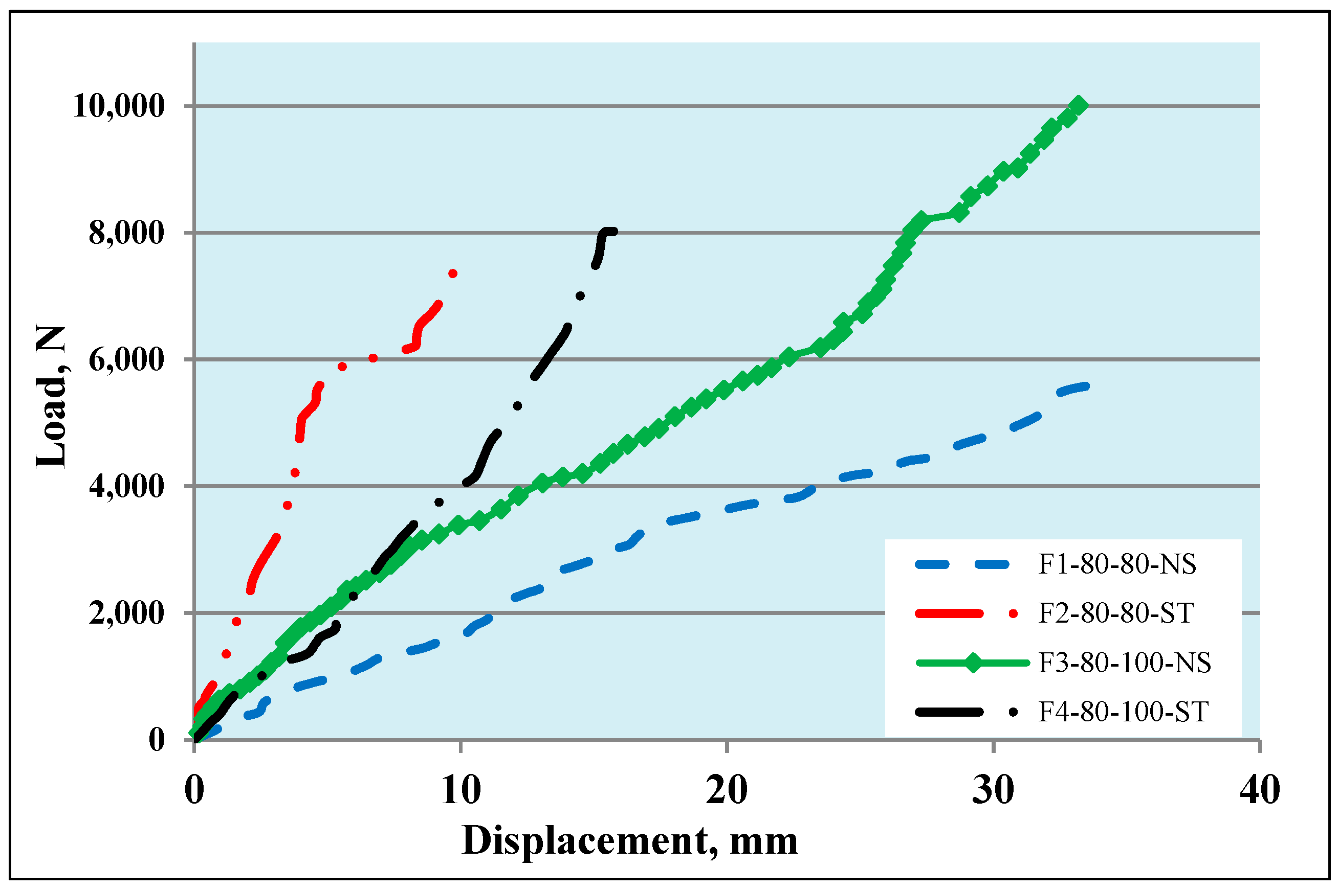
Figure 12.
Load vs. vertical downward displacements of self-form arches at the keystone.
Figure 12.
Load vs. vertical downward displacements of self-form arches at the keystone.
Figure 13.
Load vs. outward displacements of self-form masonry arches.
Figure 13.
Load vs. outward displacements of self-form masonry arches.
Figure 14.
Load vs. compression strain in the concrete voussoir.
Figure 14.
Load vs. compression strain in the concrete voussoir.
Figure 15.
Load vs. tensile strain in fabrication CFRP.
Figure 15.
Load vs. tensile strain in fabrication CFRP.
Figure 16.
Failure of tested self-form masonry arch: (
a) F1-80-80-NS, (
b) F3-80-100-NS, (
c)
Figure 2, and (
d) F4-80-100-ST.
Figure 16.
Failure of tested self-form masonry arch: (
a) F1-80-80-NS, (
b) F3-80-100-NS, (
c)
Figure 2, and (
d) F4-80-100-ST.
Table 1.
Concrete mix proportions.
Table 1.
Concrete mix proportions.
| Mixing Materials Weight (Kg) Per Cubic Meter |
|---|
| Cement | Fine Aggregate | Coarse Aggregate | Water | W/C Ratio |
|---|
| 430 | 705 | 1010 | 210 | 0.49 |
Table 2.
Hardened concrete tests.
Table 2.
Hardened concrete tests.
| Sample No. | Compressive Strength, MPa | Sample No. | Splitting Tensile Strength, MPa | Sample No. | Flexural Strength, MPa |
|---|
| Cu-01 | 33.72 | Cy-01 | 3.05 | Pr-01 | 3.945 |
| Cu-02 | 32.95 | Cy-02 | 2.98 | Pr-02 | 3.87 |
| Cu-03 | 33.1 | Cy-03 | 3.02 | Pr-03 | 3.825 |
| Average | 33.3 | Average | 3.01 | Average | 3.88 |
Table 3.
Technical and mechanical properties of carbon fiber-reinforced polymer (CFRP) composite.
Table 3.
Technical and mechanical properties of carbon fiber-reinforced polymer (CFRP) composite.
| CFRP Fabrics SikaWrap-300C | Epoxy Resin Sikadur-330 |
|---|
| Technical/Mechanical Property | Related Data | Technical/Mechanical Property | Related Data |
|---|
| Fiber orientation | 0° (unidirectional) | Chemical base | Epoxy resin |
| Wrap | Black carbon fibers 99% | Components | Two, A and B |
| Dry fiber density | 1820 kg/m3 | Appearance (Color) | Component A: white paste
Component B: gray paste
Components A + B mixed: light gray paste |
| Fiber thickness | 0.167 mm (based on fiber content) | Density | 1.30 ± 0.1 kg/L (component A + B mixed) (at +23 °C) |
| Area density | 304 g/m2 ± 10 g/m2 (carbon fibers only) | Flexural E-Modulus | ≈3800 MPa (7 days at +23 °C) |
| Fiber width | 500 mm | Tensile strength | ≈30 MPa (7 days at +23°C) |
| Dry fiber tensile strength | 4000 MPa | Tensile modulus of elasticity | ≈4500 N/mm2 (7 days at +23 °C) |
| Dry fiber modulus of elasticity in tension | 230,000 MPa | Elongation at Break | 0.9% (7 days at +23 °C) |
| Dry fiber elongation at break | 1.7% | Tensile adhesion strength | Concrete fracture (>4 MPa) on the sandblasted substrate |
Table 4.
Technical specifications of Tokyo Measuring Laboratory (TML) strain gauges.
Table 4.
Technical specifications of Tokyo Measuring Laboratory (TML) strain gauges.
| Model | Gauge Size, mm | Backing Size, mm | Gauge Materials | Backing Material | Resistance Ω | Application |
|---|
| Length | Width | Length | Width |
|---|
| PL-60-11-3L | 60 | 1 | 74 | 8 | Wire SG * | Transparent plastic | 120 | Concrete |
| BFLA-5 | 5 | 1.5 | 12.3 | 3.3 | Foil SG * | Foil | 120 | Carbon and Composite material |
Table 5.
Test results of self-form segmental concrete masonry arches.
Table 5.
Test results of self-form segmental concrete masonry arches.
| Arch Designation | Keystone Joints Opening Load, N | Initial Localized Crushing Load, N | EBR-CFRP Debonding Load, N | Voussoirs Sliding Load, N | Ultimate Load, N | Failure Mode |
|---|
| F1-80-80-NS | 570 | 3210 | 3490 | 3700 | 5590 | Partially crushed |
| F2-80-80-ST | - | - | 6540 | 7260 | 7570 | No crushing |
| F3-80-100-NS | 3150 | 3640 | 6310 | 7680 | 10,010 | Partially crushed |
| F4-80-100-ST | - | 6580 | 5880 | 6770 | 8020 | Partially crushed |
© 2019 by the authors. Licensee MDPI, Basel, Switzerland. This article is an open access article distributed under the terms and conditions of the Creative Commons Attribution (CC BY) license (http://creativecommons.org/licenses/by/4.0/).


