Review

Advances on Optical Fiber Sensors

by
Luciano Mescia
and
Francesco Prudenzano
*
Dipartimento di Ingegneria Elettrica e dell'Informazione, Politecnico di Bari Via E. Orabona 4, 70125 Bari, Italy
*
Author to whom correspondence should be addressed.
Fibers 2014, 2(1), 1-23; https://doi.org/10.3390/fib2010001
Submission received: 7 November 2013 / Revised: 6 December 2013 / Accepted: 9 December 2013 / Published: 27 December 2013
(This article belongs to the Special Issue Advances on Optical Fibers)

Abstract

:
In this review paper some recent advances on optical fiber sensors are reported. In particular, fiber Bragg grating (FBG), long period gratings (LPGs), evanescent field and hollow core optical fiber sensors are mentioned. Examples of recent optical fiber sensors for the measurement of strain, temperature, displacement, air flow, pressure, liquid-level, magnetic field, and the determination of methadone, hydrocarbons, ethanol, and sucrose are briefly described.

1. Introduction

Almost four decades have passed since the research on optical fiber sensors began in earnest. Various approaches and technologies have been utilized for measuring a number of different physical parameters, but only some types of optical fiber sensors are commercially interesting. In fact, in many cases, optical fiber sensor systems are not available in a complete form, i.e., including both detecting and signal-processing electronics. However, their future is very promising because they exhibit well known advantages such as compactness, immunity to electromagnetic interference and to ionizing radiation (γ-ray, X-ray etc.), high sensitivity, large bandwidth, and minimum weight. These properties, make optical fiber sensors key photonic devices in radiative environments, like nuclear power plants, where the detection and evaluation of radiation levels and temperature changes are very important, especially in case of accidental constraints [1]. Optical fiber sensors have been developed to measure strain, temperature, pressure, current, voltage, gas, chemical contaminant, rotation, vibration, acceleration, bending, torsion, displacement, and biomolecules [2].
Chemical optical fiber sensors for the detection of polluting substances in water, soil, and air, such as the biological sensors, optimized for medicine applications, have attracted noticeable interest because they are directly related to the quality of human life. They have been investigated as key elements of environmental monitoring systems, with the aim of preventing environmental catastrophes, and also as novel techniques for medical diagnosis. In particular, optical fiber sensor systems can avoid the collection of samples to be investigated in appositely equipped laboratories. They provide means of overcoming the drawbacks exhibited by ex-situ techniques which are invasive, time consuming and expensive. In fact, optical fiber chemical/biological sensors, enable pollution detection and/or medical diagnostic monitoring via an in-situ and slightly invasive technique.
Optical spectroscopy of water, atmosphere, soil or biological samples, is commonly performed in chemical laboratories and is based on Laser Induced Fluorescence (LIF) or Raman effects [3]. LIF or Raman equipment is generally expensive due to both the utilized light sources (and related optical components) and to the sophisticated processing electronics. In order to develop low-cost pollution and bio-medical monitoring, a promising approach concerns the optimization of microstructured optical fibers (MOFs) for sensing. In fact, in recent years, a number of sensors made of suitable MOFs have been theoretically and experimentally investigated for the measurement of a large variety of physical and chemical parameters [4,5,6,7,8,9,10,11,12].
Both conventional fiber optic and MOF sensors can be based on fiber gratings, interferometers, scattering/reflecting, Faraday rotation, fiber-optic gyroscopes, fluorescence, luminescence, and interaction of evanescent electromagnetic field structures.
Most of the aforesaid fiber sensors employ optical gratings which, under phase matching conditions, can couple different propagation modes. Optical fiber gratings can be fabricated by employing different techniques, e.g., the exposure of the optical fiber core to an intense optical interference pattern [13]. Permanent gratings in an optical fiber were first obtained by Hill et al. [14]. In [14] an Argon-ion laser radiation, at 488 nm, was launched into a germania-doped fiber; after some minutes most of the launched light was reflected. Successively, strain and temperature tuning of the fiber grating were investigated and suitable spectral measurements confirmed the fabrication of a fiber Bragg grating (FBG) via the photosensitivity effect. In fact, a coherent high power laser beam can interfere with the light reflected back from a discontinuity to produce a standing wave pattern within the optical fiber. If the optical fiber, after ultraviolet light exposure, is suitably annealed the grating becomes permanent. It was demonstrated that the gratings facilitated coupling to higher-order leaky modes. After this experiment, numerous scientific papers on FBGs and their applications were produced.
Different techniques have been utilized for grating writing. In the holographic technique, two overlapping ultraviolet light beams interfere producing a periodic interference pattern on the side of the fibers [13]. Therefore a periodic refractive index grating is written in the core because the fiber cladding is transparent to the ultraviolet light whereas the fiber core, generally germanium doped, highly absorbs the ultraviolet light. The phase mask technique is based on the fabrication of a flat slab of silica glass, transparent to ultraviolet light but having one of the flat surfaces with a one dimensional periodic corrugation. This corrugation, can be obtained via an etching technique and by using photolithographic techniques. The optical fiber is placed close to the corrugations of the phase mask and then irradiated by ultraviolet light which is incident normal to the phase mask [13].
FBGs are now commercially available and they find extensive application in many areas such as, filtering, routing, lasing and amplification of optical signals, and sensing of various measurands.FBG-based wavelength interrogation modules and broadband light sources, have been optimized for the safety monitoring of large structures, e.g., bridges, towers, dams, and railways [15,16,17,18,19,20,21].
Long period gratings (LPGs) have been exploited in the construction of filters, gain flatteners for erbium-doped fiber amplifiers, dispersion compensators, sensors, etc. [22,23,24,25,26,27,28,29,30,31,32,33,34,35,36,37]. They have been fabricated in MOF, by employing different techniques, to obtain strain or refractive index sensors [28,29]. Moreover, LPGs were fabricated in all-solid photonic bandgap fibers (PBGFs) by UV illumination [36]. In particular, the exploitation of a tunable slit with a high-precision motorized linear stage and a suitable PBGF laser pulse exposition allowed an optimized LPG fabrication process [36]. The first fabrication of femtosecond-laser-drilled structural LPGs in a large mode area PCF was reported in [37]. Different techniques allowing grating inscription into the MOF core and cladding have been demonstrated in a number of experimental works [23,25,26,30,35,36,37].
In this paper, some recent advances on optical fiber sensors are reported. Specifically, only a few recent investigations are cited for FBGs, LPGs and evanescent field sensors.

2. Optical Fiber Gratings as Key Elements of Sensors

The core refractive index perturbation ∆n(z) along the fiber longitudinal direction z, constituting a grating, can be expressed as reported in [31]:
Fibers 02 00001 i001
where n1 is the core refractive index, Λ is the grating period, m is the induced-index fringe modulation, and σ(z) is the slowly varying envelope of the grating.
The well-known coupled mode theory CMT can be employed to find the equations describing the electromagnetic field propagation along the grating, by considering the slowly varying envelope approximation (SVEA) [31]. Coupled equations can be correctly written when grating inscription induces a weak perturbation on the propagation modes and the electromagnetic field amplitudes of the forward and backward modes can be calculated.
A strong mode interaction can be obtained in the grating at the wavelength where both mode phase matching (phase synchronism) and a sufficient mode overlap occur. Therefore, different modes can exchange power between them. The local reflectivity is the complex ratio of the forward and backward wave amplitudes [13]. FBGs, characterized by a short period, typically couple the forward propagating core mode to the backward propagating one. Chirped fiber gratings exhibit a large reflection spectrum. They are generally utilized when the phenomenon that each wavelength component is reflected at different positions in different delay times must be exploited for the fabrication of specific devices [2]. Tilted fiber gratings exhibit different characteristics and they can be used to couple the forward propagating core mode to the backward one and to a backward propagating cladding mode. LPGs, characterized by a long period, are generally designed to allow the power exchange of a forward propagating core mode with the power of selected forward propagating cladding modes.
When a core mode is coupled with a cladding mode the transferred electromagnetic energy is affected by the mode phase mismatch (displacement from the phase matching condition) which can be due to a variation of a number of different measurands such as wavelength, temperature, stress, fiber bending etc. Therefore optical sensors can be obtained.

2.1. Fiber Bragg Grating Sensors
An FBG is a distributed mirror at the Bragg wavelength, i.e., at the phase-matching condition λB = 2neff/Λ, where λB is the Bragg wavelength, neff is the effective index of the interfering guided mode [16]. Fiber laser cavity can be typically obtained by employing two different mirror implementations: (i) distributed Bragg reflector (DBR) formed by two cascaded wavelength-matched FBGs; and (ii) distributed feedback Bragg (DFB) structure where a phase-shifted FBG is distributed in an active fiber [17,18,19]. DBR and DFB laser sensors attract considerable interest because of their excellent characteristics [20,21]. Moreover, fiber grating laser sensors can be based on wavelength encoding or on a polarimetric heterodyning sensor.
FBGs allow fine control of fiber laser cavity by finely tuning their distributed reflectivity. This potential is strategic in the optimal design of both conventional and MOF fiber lasers [38,39,40,41,42,43,44,45] and therefore in the design of DBR and DFB laser sensors.
A heavy limitation of FBG strain sensors lies in their high temperature cross-sensitivity, this drawback is worsened by the difficulty to measure strain and temperature simultaneously. In [46] a hybrid sensor overcoming the aforesaid limitation has been proposed. It operates in the intensity domain, by converting into intensity changes two different items: (i) the polarization information from a polarization-maintaining photonic crystal fiber PM-PCF fiber sensor; and (ii) the wavelength information from FBG. A 3 dB coupler has been used to split the signals between the FBG sensor and the polarimetric sensor. A polarizer and an analyzer at the input and output of the PM-PCF have been used to measure the polarization variation due to the strain and temperature. A macrobend fiber-based edge filter has been used to convert the FBG wavelength variations due to the strain and temperature into light intensity changes. The output powers were measured by employing two photodiodes [46]. Also in displacement measurements, the FBG sensor output can be obtained by using an edge filter to interrogate the resonant wavelength [47] or a cantilever to transfer/convert the displacement into the chirp profile of the FBG [48].
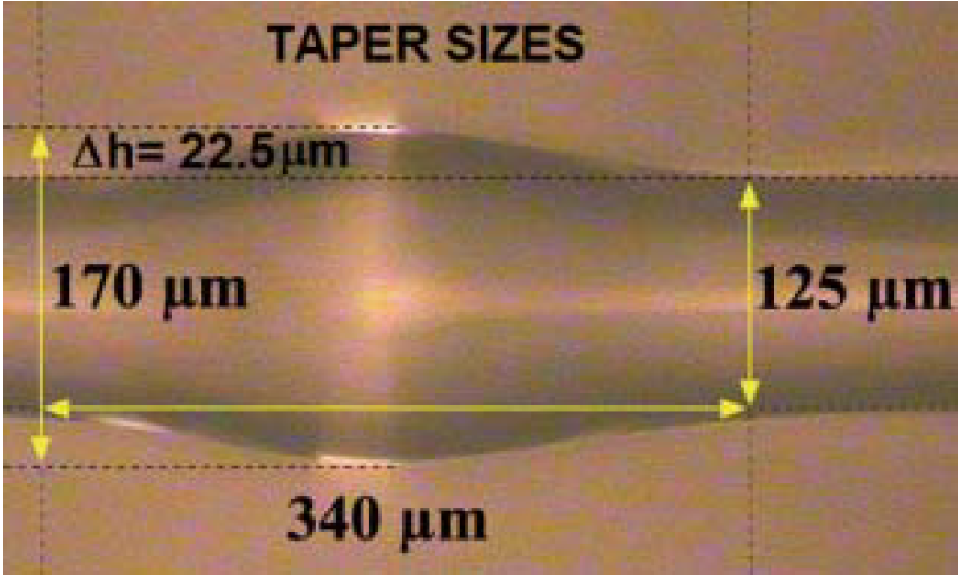
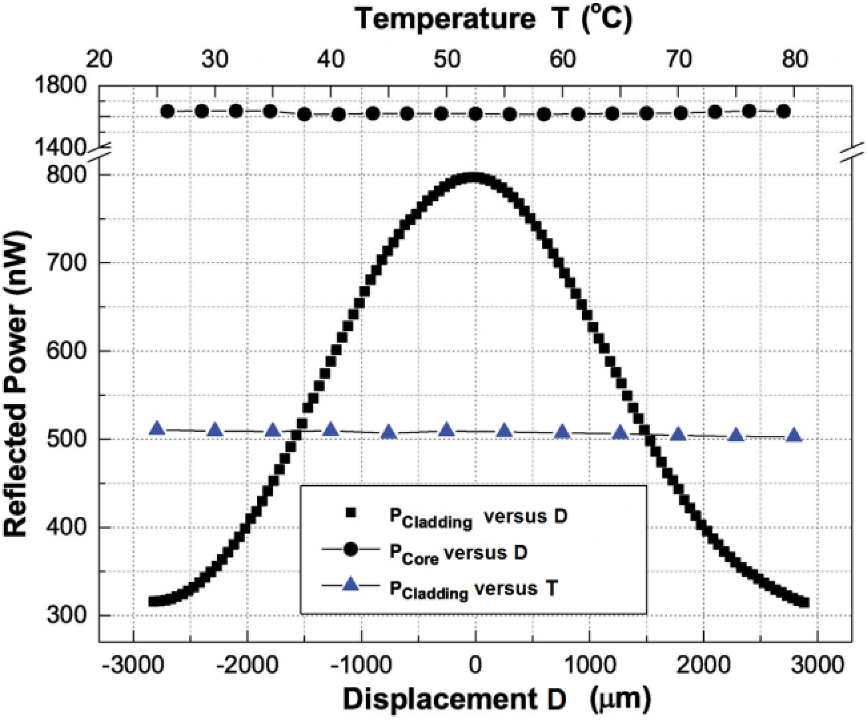
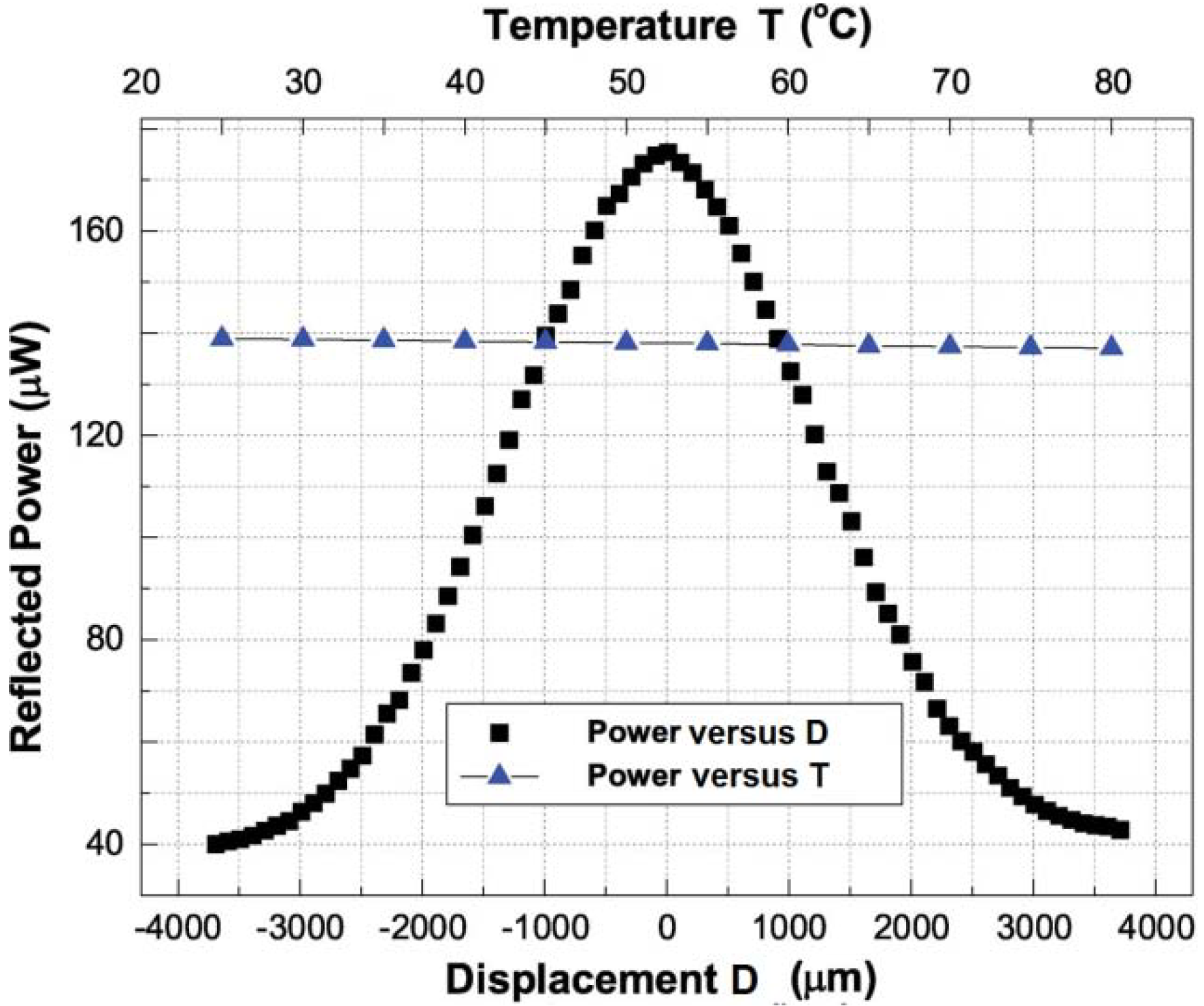
Optical fiber sensors based on cladding-mode backward recoupling constitute an interesting technique to obtain high sensitivities [49,50,51,52,53]. In fact, an optical fiber cladding mode shows much higher sensitivity to micro deformations, like structural bending, compared to a fundamental core mode. For example, in [54] a structure for cladding-mode backward recoupling has been fabricated by including the up-taper and the Bragg grating as shown in Figure 1. The up-taper microscope photo is reported in Figure 2. Cladding-mode backward recoupling is the key principle on which the sensor is based. The structure is illuminated by a broad-band source from the same interrogation fiber. The up taper is designed to allow mode coupling between copropagating modes. The Bragg grating allows wavelength-selective mode coupling between counter-propagating modes. At the up-taper, the core mode exhibits loss and the cladding modes are excited. The excited cladding modes travel to the fiber grating with low attenuation if the sensor is kept straight. As described in [54], the guided core mode is coupled to the backward-propagating cladding ones by the grating. Then the cladding modes are recoupled to the guided core mode at the up taper. The cladding modes excited at the up taper are recoupled to the guided core mode by the fiber grating. Following this, the guided core mode travels into the interrogation fiber. Mode coupling between counter-propagating cladding modes can be neglected. Figure 3 illustrates cladding mode power and core mode power versus displacement and cladding mode power versus temperature. An improvement of the sensor performance is obtained by employing suitable uniform chirped FBGs (CFBGs) as illustrated in Figure 4. With the same measurement set-up, by employing the CFBG the maximum reflection power is increased from 800 nW (for the FBG) to 176 µW (for the CFBG).
Figure 1. Schematic of cladding-mode backward recoupling structure including the up taper and the fiber Bragg grating proposed in [54].
Fibers 02 00001 g001
Figure 2. Microscope photo of the up taper constructed in [54].
Fibers 02 00001 g002
Figure 3. Cascade of up-taper and fiber Bragg grating (FBG) [54]. Behavior of cladding mode and core mode power versus displacement and cladding mode power versus temperature.
Fibers 02 00001 g003
Figure 4. Cascade of up-taper and chirped FBG (CFBG) [54]. Behavior of cladding mode power and core mode power versus displacement and cladding mode power versus temperature.
Fibers 02 00001 g004
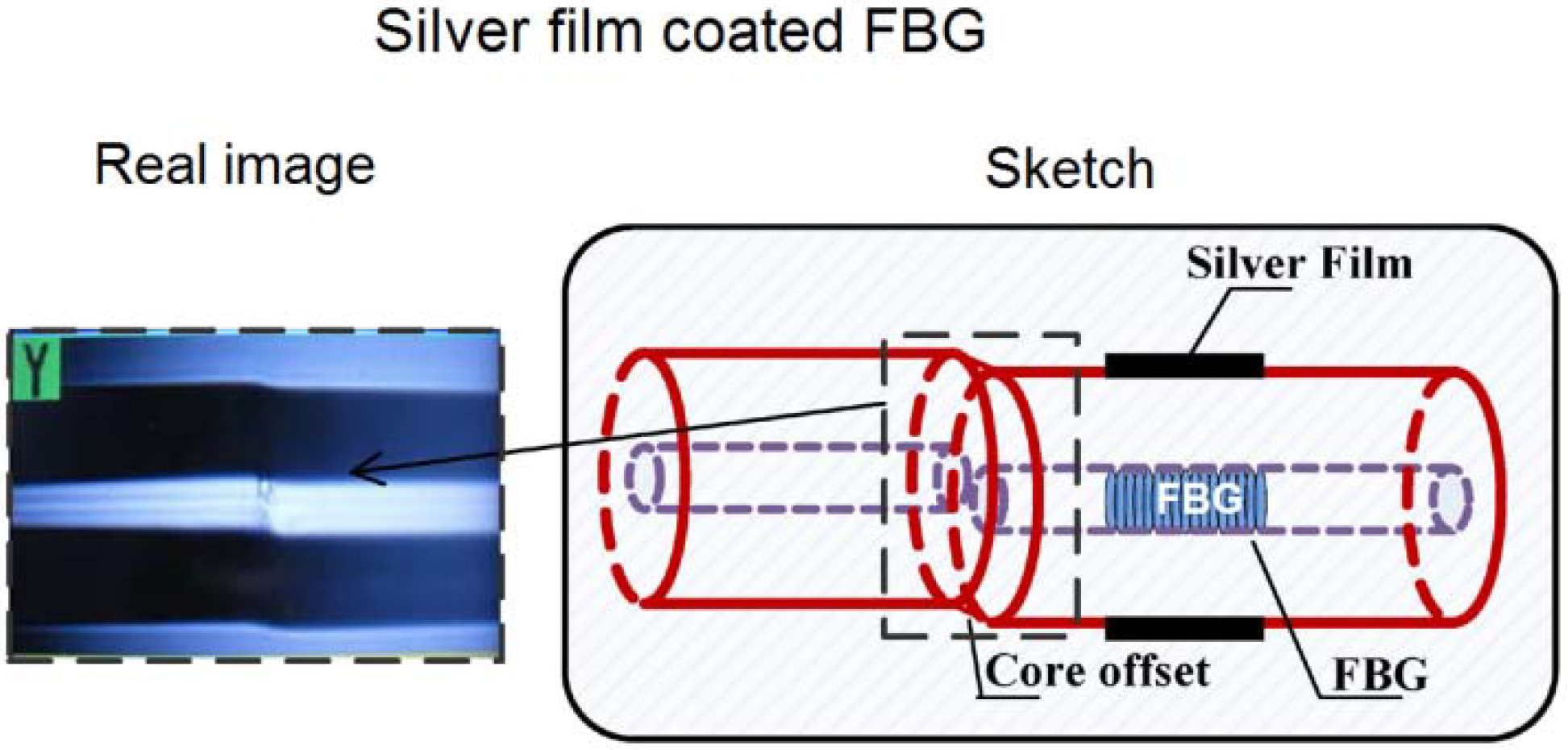
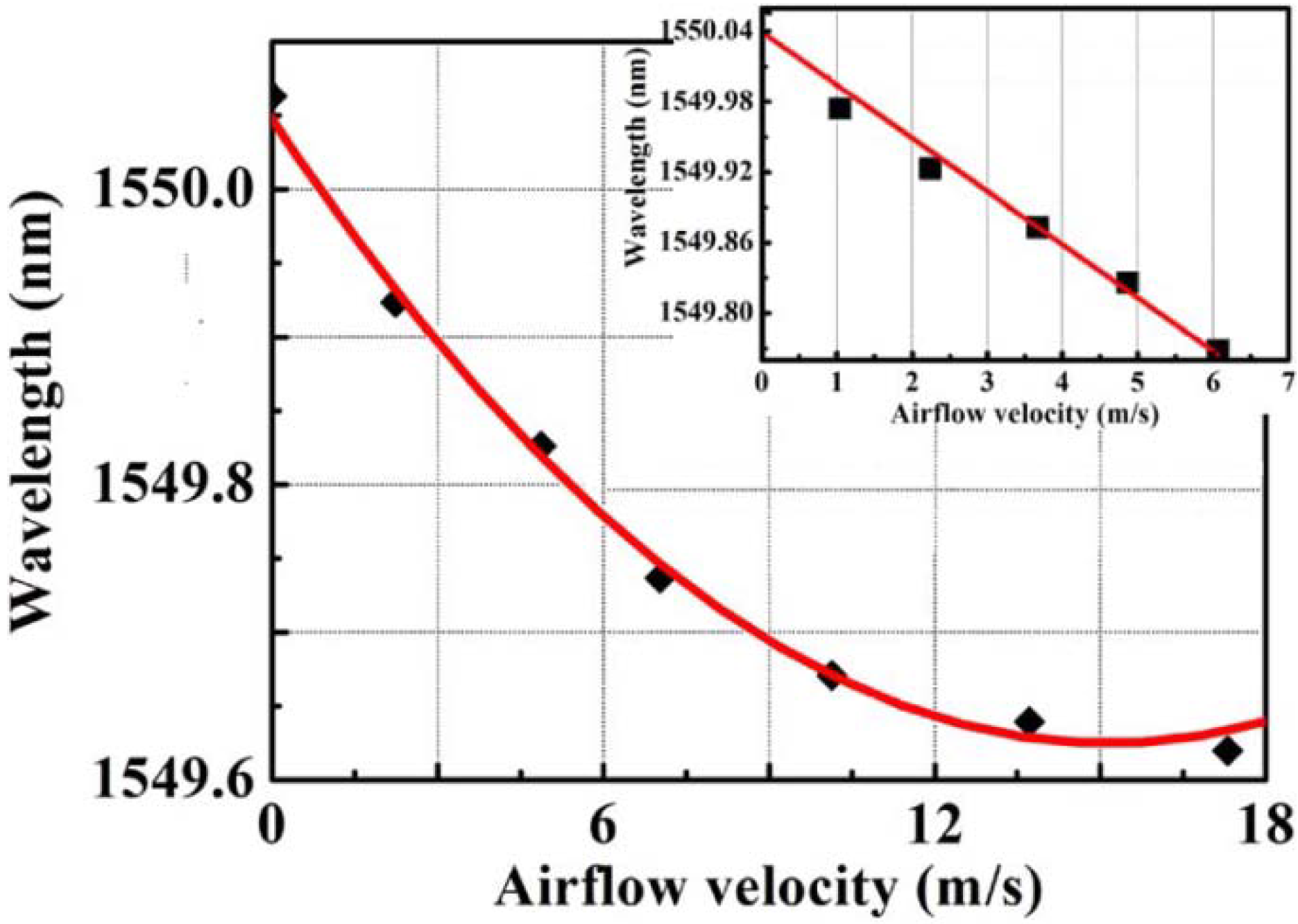
Gas or liquid flow measurement is required in the automotive industry, in material processing, in marine applications and in a number of other areas. Fiber optic technology has been largely employed [55,56,57,58,59]. For example, an optical fiber thermal anemometer based on a short silver-film-coated FBG and a core-offset fusion splice is proposed in [60]. The set-up is schematically shown in Figure 5. The core-offset splice is performed in order to couple most of the laser power from the fiber core to the cladding, see photograph and sketch of the core-offset splicing point. The silver coating close to the FBG absorbs the pump laser and generates heat. A pump laser at 1450 nm with a maximum output power of 450 mW has been used to heat the FBG. Therefore, the generated heat increases the temperature and thus the Bragg wavelength of the FBG. The anemometer is cooled down by the air flow through the anemometer. As a consequence, the Bragg wavelength shifts toward the short wavelength. The velocity of the air flow can be measured from the amount of wavelength shift of the FBG with respect to the nominal Bragg wavelength. In this way, a highly sensitive anemometer is obtained. A linear response of 45.3 pm/m/s and a high resolution of 0.022 m/s were achieved for an airflow velocity below 6 m/s. The sensor characteristic is shown in Figure 6, where the Bragg wavelength versus the airflow velocity is illustrated.
Figure 5. Schematic of the set-up proposed in [60]. FBG-based thermal anemometer.
Fibers 02 00001 g005
Figure 6. Resonant wavelength versus applied airflow velocity of the anemometer using silver-coated fiber Bragg grating [60].
Fibers 02 00001 g006
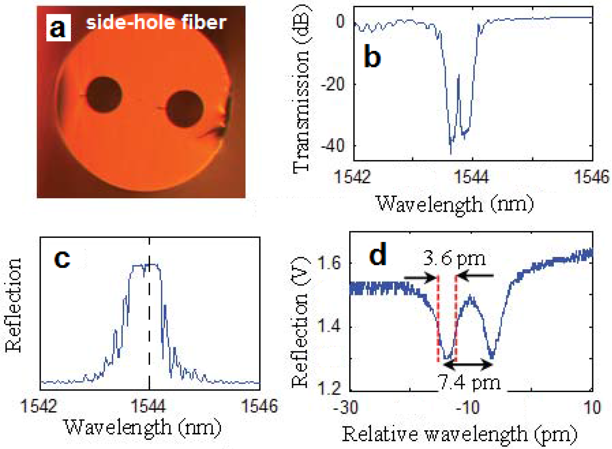
Pressure sensors are desired in a number of areas e.g., industry, structural safety monitoring, oil wells, and power plants. Pressure sensors based on fiber Bragg gratings (FBGs) on side-hole fibers are very attractive [61,62,63,64]. In [65] a fiber-optic pressure sensor based on a π-phase-shifted fiber Bragg grating (πFBG) fabricated on a side-hole fiber is reported. A πFBG can be considered as aFabry-Perot (FP) resonator formed by two FBG mirrors. The side-hole fiber consists of two air channels running through the fiber cladding as shown in Figure 7. A hydrostatic pressure acting on the fiber surface induces an anisotropic stress distribution. Therefore a fiber birefringence via the photoelastic effect occurs. The fiber birefringence, proportional to the hydrostatic pressure, can be measured by evaluating the separation of the FBG peaks associated with the two polarization states. Therefore the FBG reflection spectrum gives a measurement of the pressure. The temperature can be simultaneously measured by monitoring the Bragg wavelength shift of the FBG peak. The performance can be enhanced by employing two πFBGs [65].
Figure 7. Fiber-optic pressure sensor based on a π-phase-shifted fiber Bragg grating (πFBG) fabricated on a side-hole fiber [65]. (a) Section of the side-hole fiber; (b) Transmission versus wavelength; (c) and (d) Reflection versus wavelength of a πFBG fabricated on the side-hole fiber.
Fibers 02 00001 g007
The πFBG demonstrated in [65] is 8.3 mm long and the line width of each spectral notch is 3.6 pm, corresponding to a quality factor of 4.3 × 10⁵. The spectral notch separation exhibited a sensitivity of 20 pm/kpsi to pressure. The Bragg wavelength shift exhibited a sensitivity of 11.4 pm/°C to temperature. A pressure detection limit of 1.4 psi and a temperature detection limit of 0.0025 °C were obtained.

2.2. Passive Long Period Grating Sensors
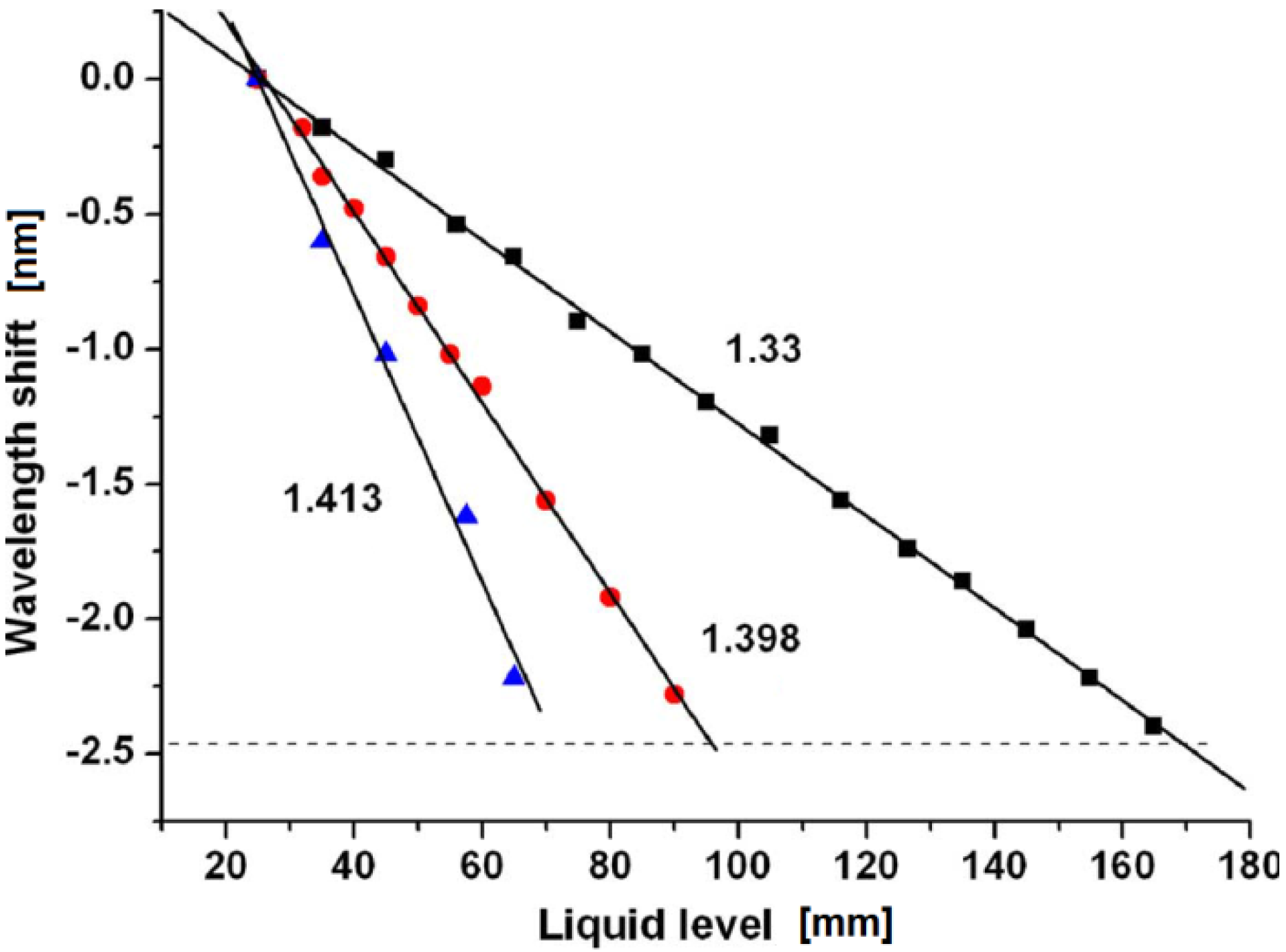
LPGs couple light very efficiently between two co-propagating modes in optical fibers. The resonance wavelength of an LPG, such as for the other gratings, is determined by the mode phase matching condition and by mode overlapping. It depends on the effective refractive index difference between these two coupled modes. Similarly to that occurring for FBGs, LPGs can be utilized to construct sensors for the detection of various physical parameters, including external refractive index, temperature, bending, loading, and liquid level [66,67]. LPG-based liquid-level sensor LLSs exhibit high sensitivity to external liquid (due to the light coupling to cladding modes) and high feasibility. In [68] an optical liquid-level sensor (LLS) based on long period fiber grating (LPG) interferometer was experimentally demonstrated. More precisely, an in-fiber Mach-Zehnder interferometer was obtained by employing two identical 3-dB LPGs. The sensing element, exposed to different liquids, is the fiber portion between two LPGs. The experimental sensor characteristic exhibited good linearity and a large measurement range. In Figure 8 the wavelength shift versus the liquid level is depicted for different refractive indices of the surrounding medium (liquids): 1.33 (rectangles), 1.398 (circles), and 1.413 (triangles) when the sensing element between two gratings is 250 mm long.
Figure 8. The relationship between peak wavelength and liquid-level with the surrounding liquid refractive indices [68].
Fibers 02 00001 g008
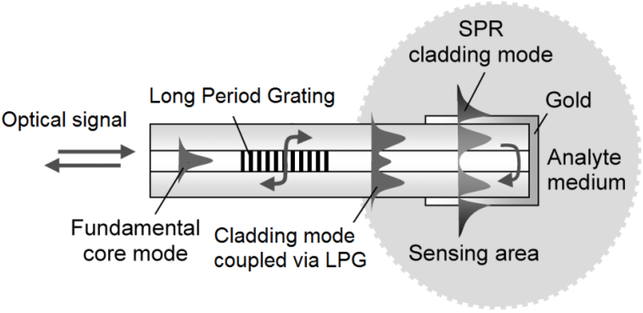
LPGs such as FBGs can be utilized to enhance particular physical effects, e.g., Surface Plasmon Resonance (SPR). SPR is employed in a high number of sensors [69,70,71,72,73,74,75], it is based on electron density oscillations, propagating as transverse-magnetic (TM) polarized waves at the interface between a metal and a dielectric medium. These waves are highly attenuated evanescent ones. LPG can be employed to achieve SPR of a single cladding mode [76,77,78,79]. In [80] the fabrication of a fiber-optic refractive index (RI) sensor has been reported. A LPG has been fabricated to achieve surface plasmon resonance of a single cladding mode at the gold-coated tip of a single-mode fiber. The set-up is shown in Figure 9.
Figure 9. Set-up of the fiber-optic surface plasmon resonance (SPR) sensor proposed in [80].
Fibers 02 00001 g009
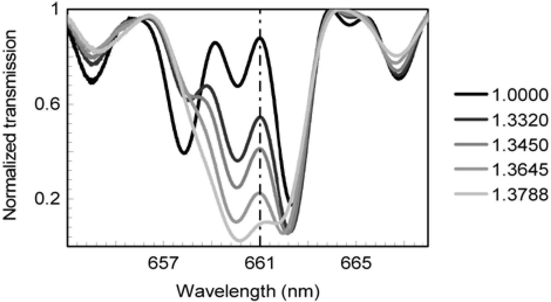
The sensor is based on a single-mode fiber. The fiber tip is covered by a gold-plate, this part is the sensing area which is close to core LPG. A thin poly-directional coating supports the formation of SPR cladding modes. This structure has been proposed to obtain a biosensor. In fact, the power attenuation is strongly affected by the refractive index of the surrounding analyte medium. Small RI changes, e.g., caused by biomolecular binding processes, induce changes of the transmitted optical power. The LPG is designed for bidirectional coupling of the fundamental core mode with a cladding mode. Then the cladding modes are converted into an SPR cladding mode. The sensor has exhibited a high level of sensitivity in a miniaturized sensing area. LPGs with periods of 114 µm were fabricated to couple in to the designated cladding mode HE1,20 at a wavelength of around 660 nm. LPG lengths of 30 mm enabled mode coupling of 15 dB.
Figure 10 shows the measured normalized transmission spectra for increasing refractive index of the surrounding medium (1–1.38). The LPG resonances are close to 660.6 nm. The vertical dashed line is the spectral location of the maximum SPR transmission loss.
Figure 10. Normalized transmission spectra of the Miniaturized Long-Period Fiber Grating Assisted Surface Plasmon Resonance Sensor [80].
Fibers 02 00001 g010
LPGs have been inscribed in MOFs filled with ferrofluid. Figure 11 shows the microscopic photograph of the Ferrofluid-Infiltrated Microstructured Optical Fiber Long-Period Grating reported in [81]. The cladding modes can be tuned more easily than the core mode. The mode dispersion curves are affected by the applied magnetic field. An enhancement of the applied magnetic field gradually reduces the refractive index of ferrofluid. This effect causes the decreasing of the effective refractive index difference between core and cladding modes, as shown in Figure 12. The MOF-based LPG has shown a sensitivity of 1.946 nm/Oe for a magnetic range of 0–300 Oe. The potential applications as a high-sensitivity magnetic-field sensor are apparent.
Figure 11. LPG inscribed in microstructured optical fiber (MOF) filled with ferrofluid [81].
Fibers 02 00001 g011
Figure 12. Difference between cladding-mode and core-mode effective indices for different applied magnetic fields [81].
Fibers 02 00001 g012

2.3. Active Long Period Grating Sensors
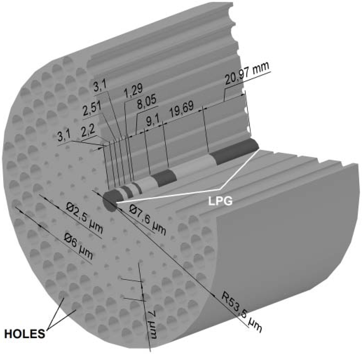
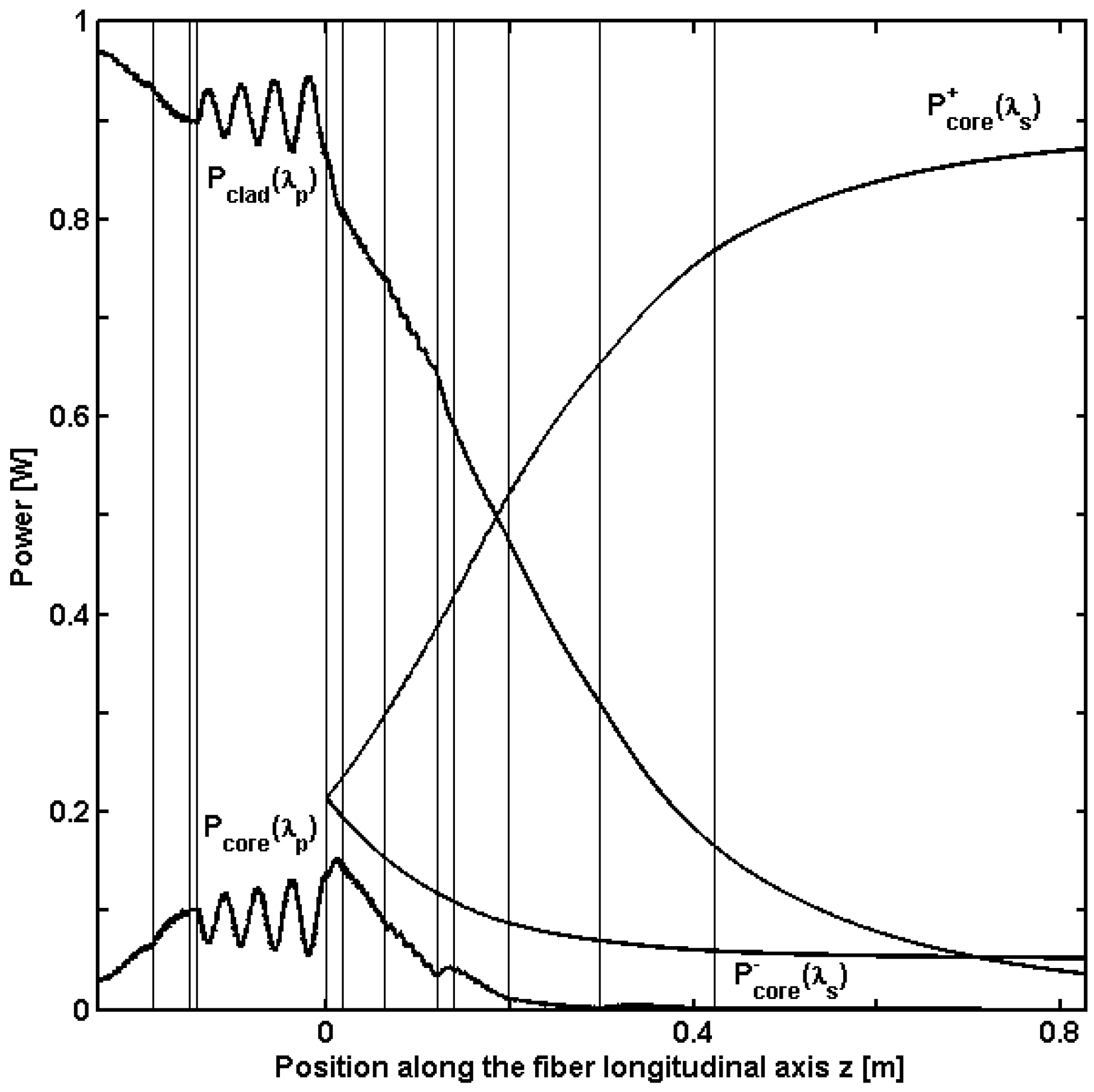
Laser sensors, include active behavior (e.g., due to the rare earth doped materials) and grating transmission spectra (e.g., FBG or LPG), which can be highly sensitive to the variation of some measurands. In [82,83] the design criterion to choose the suitable spatial distribution of multiple long period gratings MLPG couplers with respect to a MOF laser cavity was identified. The reported model extensively illustrates the behavior of the LPG in active medium, via the coupled mode equation and the rate equation of the rare earth ion population. In fact, it describes an Yb3+-doped MOF laser cavity by taking into account the presence of different MLPGs inscribed within the core. The MLPGs reported in [83] enable the interaction among the two-fold degenerate fundamental mode guided in the fiber core (HE11) and the inner cladding modes, at the pump wavelength. The model includes the following kinds of couplers: (a) MLPGs-P, Multiple Long Period Gratings in Passive fibers, i.e., grating cascades inscribed in the undoped region, just outside the laser cavity; (b) MLPGs-A, Multiple Long Period Gratings in Active fibers, i.e., grating cascades inscribed within the laser cavity (see Figure 13); (c) DS-MLPGs, Double Stage Multiple Long Period Gratings, i.e., a combination of passive grating cascades, inscribed outside the laser cavity, and active ones, inscribed within the laser cavity, are employed). Figure 14 shows the power in the cladding at pump wavelength Pclad(λp), in the core at pump wavelength Pcore(λp), forward and backward in the core at signal wavelength P+core(λs), Pcore(λs) versus the position along the fiber longitudinal axis z for the DS-MLPGs. The vertical lines represent the grating cascade along the fiber axis.
Figure 13. 3D sketch of the ytterbium-doped MOF laser with the MLPGs-A grating cascade [83].
Fibers 02 00001 g013
Figure 14. Power Pclad(λp), Pcore(λp), P+core(λs), Pcore(λs) versus the position along the fiber longitudinal axis z, DS-MLPGs [83].
Fibers 02 00001 g014
Even if MLPGs-P, MLPGs-A and DS-MLPGs were designed in [83] to increase the pump power transfer from the inner cladding modes at the pump power towards the fundamental core mode of the MOF laser, the model can be employed for designing active MLPG sensors since both (i) the LPG transmission spectrum; and (ii) its efficiency as power coupler can be affected by different measurands (e.g., bending or strain).
Since the phase matching condition of the coupled modes in the LPG is strongly affected by small changes in the effective index difference, LPG refractive index sensors are feasible. It is well known that by filling the holes of MOFs with some functional material, their modal and dispersion properties may change strongly. This also affects the tuning properties of LPGs inscribed in such fibers [81]. Therefore, MOF based LPGs are highly sensitive/tunable devices [84,85,86].
Recently LPGs, similarly to FBG, were proposed for optical pulse shaping and coding techniques [87,88,89,90,91]. These topics are interesting within communication systems and, in addition, to develop a large interrogating optical network e.g., based on Optical Time Domain Reflectometer (OTDR) techniques and communication protocols.

3. Evanescent Field, Hollow Core, Liquid Filled and Exposed Optical Fiber Sensors
Optical fiber evanescent wave sensors are a valid alternative for chemical analysis [92]. Distributed optical fiber sensors based on evanescent field interactions enable the measurement of chemical distributions over very long distances. Their potential applications are in structural health monitoring, environmental monitoring, homeland security, and many other applications [93,94,95,96,97,98,99,100].
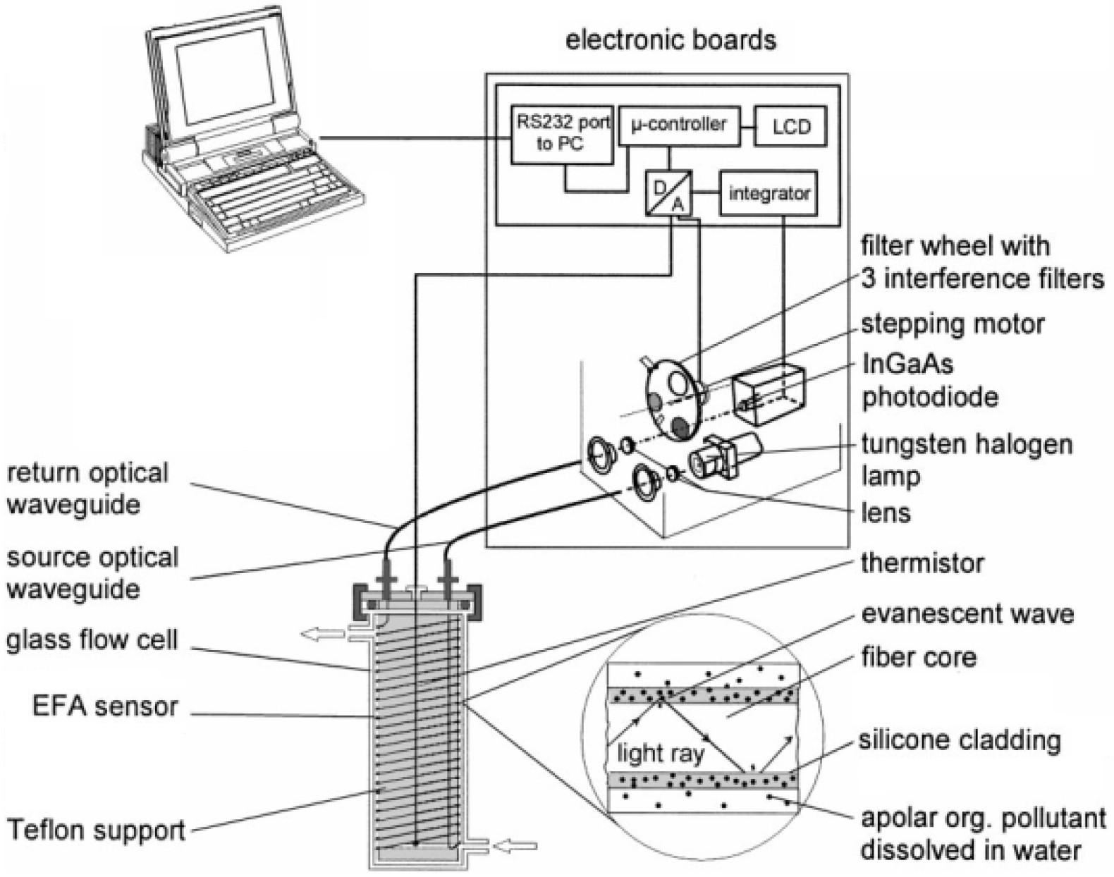
The optimization of evanescent field optical sensors plays an important role in the development of low-cost pollution monitoring. In this case, the detection is obtained via transmittance or absorption measurements at the wavelength where the contaminant exhibits the highest absorption peak. In [101,102,103,104,105,106,107] optical sensing of hydrocarbons in air or in water, using UV or NIR evanescent field optical sensors was reported. Figure 15 illustrates the example of the set-up reported in [106].
Figure 15. Evanescent field absorption sensing principle and instrumental set-up of coiled fiber-optic sensor installed in a flow cell and and NIR bandpass filter photometer unit [106].
Fibers 02 00001 g015
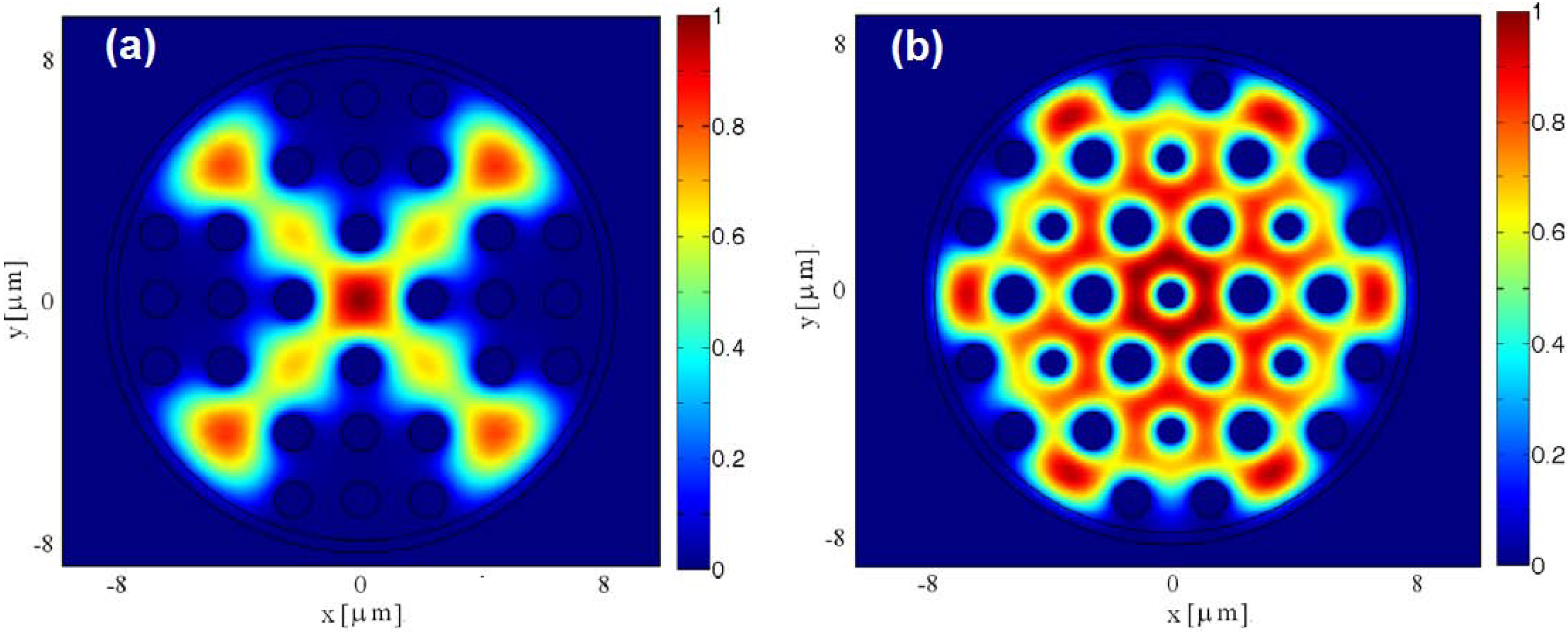
In [108,109,110] fiber optic sensors for biosensing are reported. In particular in [108] the design of a photonic crystal fiber sensor for methadone detection in water was performed. The sensor feasibility was numerically investigated by employing a Finite Element Method (FEM) numerical code. The fiber cross section, including a polymeric cladding as sensitive layer, was optimized. In the design, the thickness of the polymeric layer, the hole diameter, the hole-to-hole spacing and the transversal distribution of the holes were parametrically varied. The design of the fiber geometry was performed to balance competing requirements such as the reduction of the number of the propagating modes and the improvement of the evanescent field optical power interacting with the sensitive layer. The polymeric sensitive layer interacts with the water polluted by the methadone. At equilibrium, the contaminant concentration (Cp) in the polymer and in the water (Cw) are linked by the distribution constant Kp/w = Cp/Cw, whose value is peculiar to that of the used polymer. The methadone induces the change of the polymer absorption loss which increases by increasing the contaminant concentration. Therefore, a change of the imaginary part of the complex effective refractive index of the guided modes occurs. In particular, the light guided in the fiber core suffers a power attenuation due to the methadone. The optimal UV operation wavelength is that at which the methadone absorption peak occurs. Figure 16 shows the simulated transverse profile of the electric field of the HE11 guided propagation mode (a) for square-lattice; and (b) for the hexagonal-lattice photonic crystal fibers.
Figure 16. Simulated transverse profile of the electric field of the HE11 guided propagation mode (a) for square-lattice; and (b) for the hexagonal-lattice photonic crystal fibers [108].
Fibers 02 00001 g016
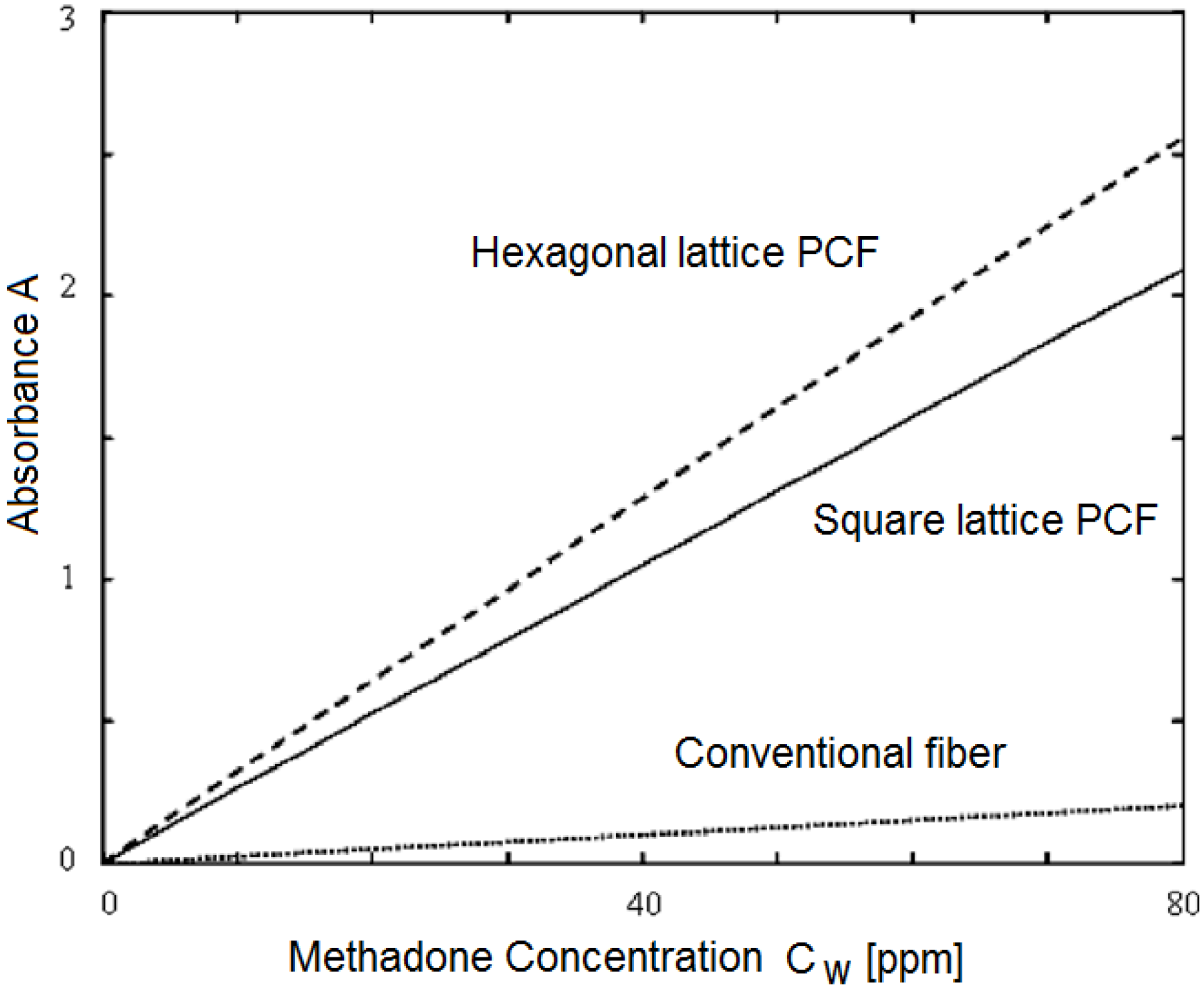
Figure 17 depicts the absorbance A versus the methadone concentration for the square-lattice photonic crystal fibers (PCF) (full curve), hexagonal-lattice PCF (dash curve) and conventional step-index fiber (dot curve) having core radius R = 8 µm and PDMS thickness tc = 0.4 µm, for the sensor length L = 15 cm.
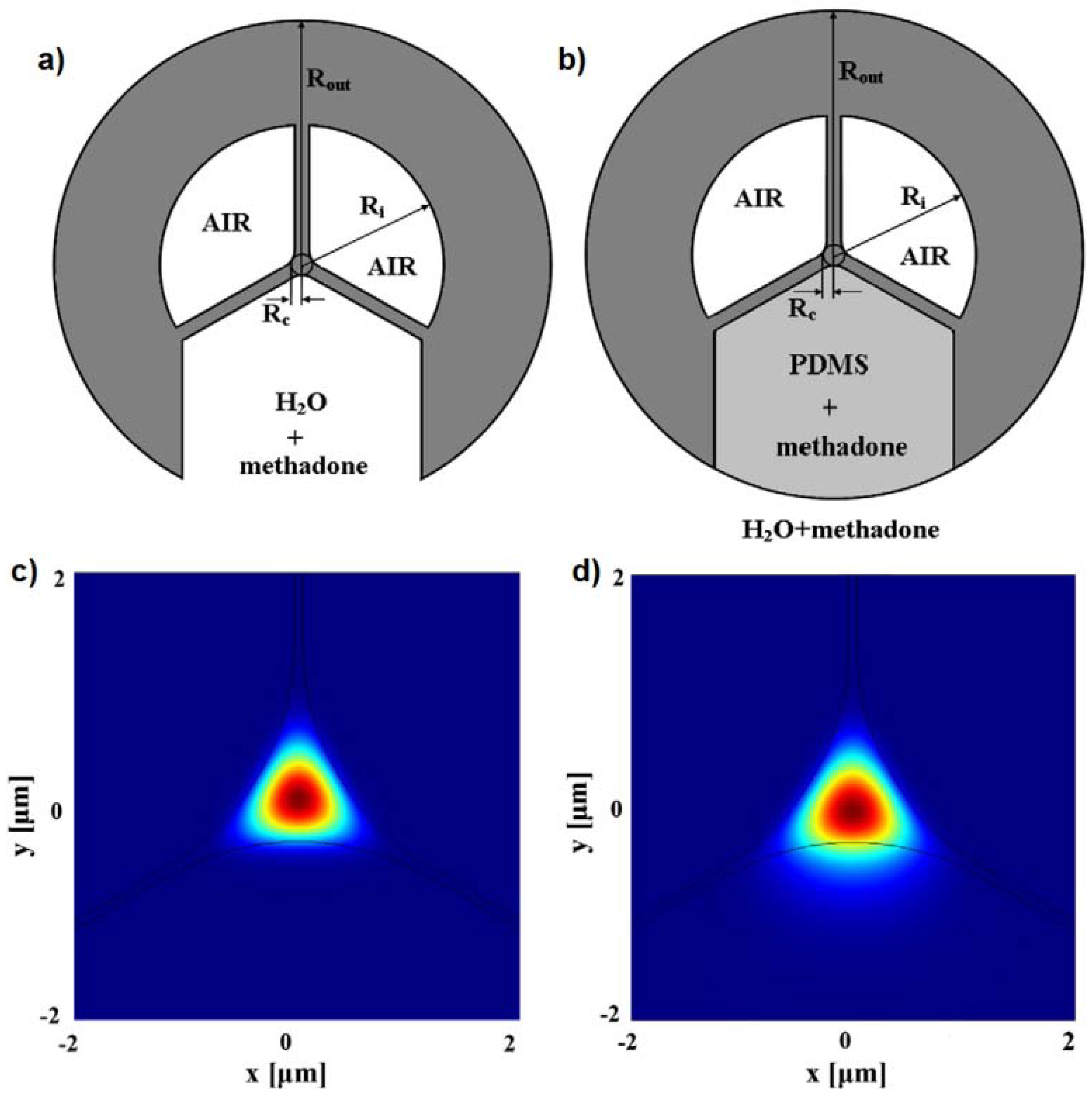
In [109] the design of a silica exposed-core fiber sensor for methadone detection in water was reported; exposed-core fiber coated with polydimethylsiloxane PDMS was fabricated at the University of Adelaide in order to further enhance the sensitivity. Figure 18 reports the sketch of (a) exposed-core fiber; and (b) exposed-core fiber with PDMS coating. By simulation the absorbance sensitivity for a fiber length L = 10 cm for the exposed core fiber without PDMS is close to A = 0.3 × 10⁻⁶ [ppb−1] while it is close to A = 0.011 [ppb−1] for exposed core fiber with PDMS. Lead silicate glass (F2) was considered in the simulation as an alternative to silica glass and different contaminants (benzene, toluene etc.).
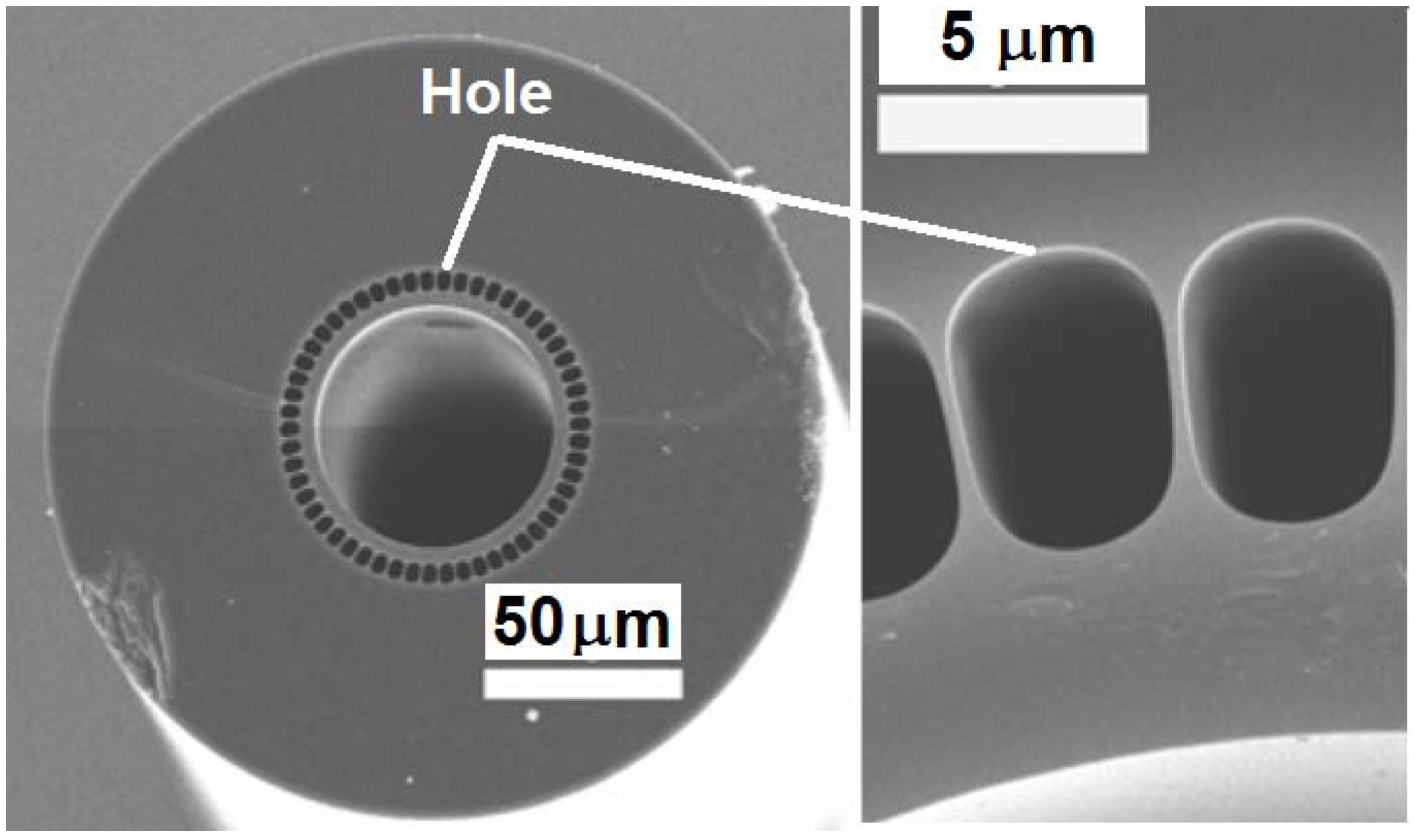
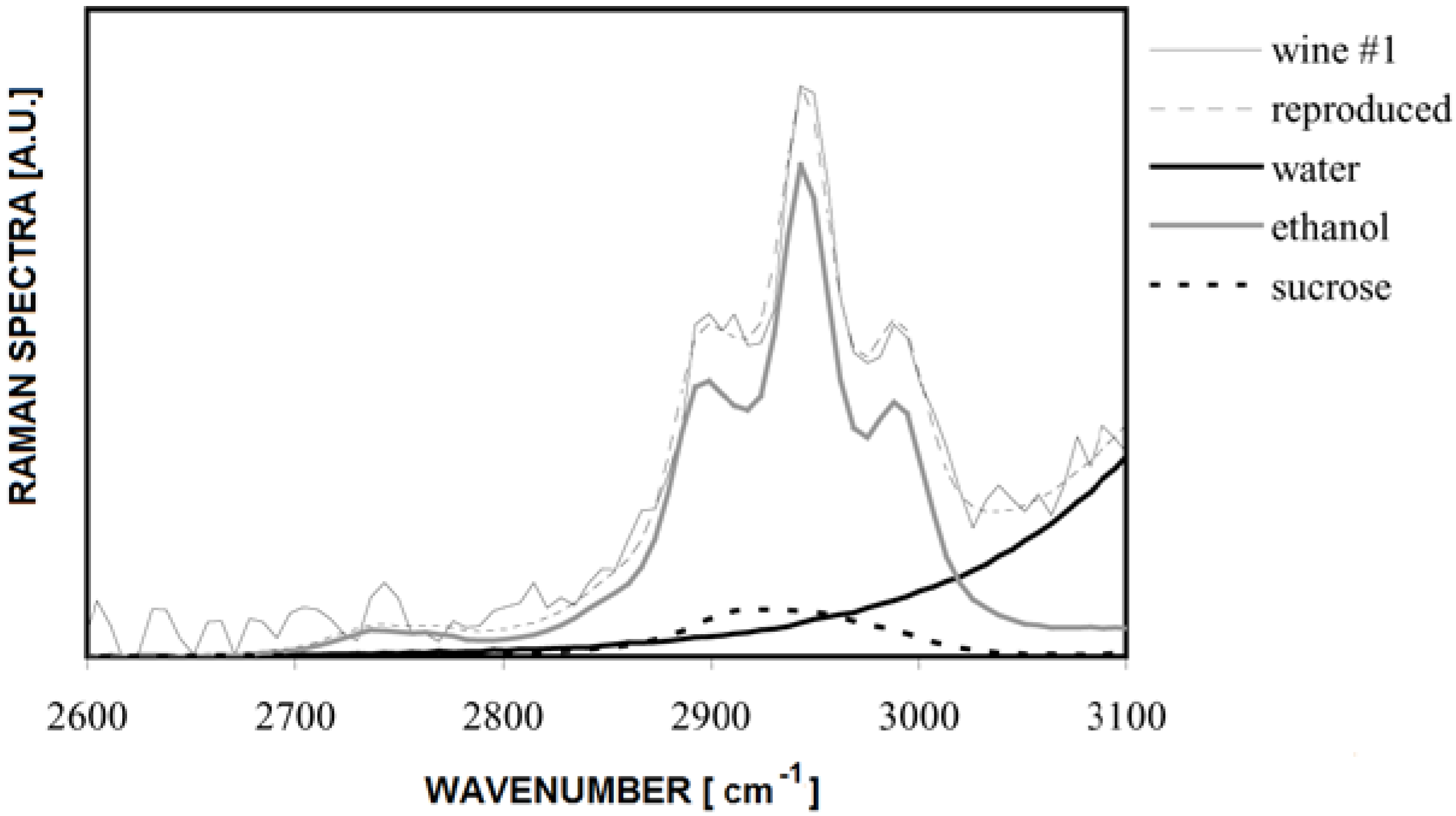
The air holes of ad-hoc designed MOFs can be filled with different materials [111,112,113]. Hollow-core MOFs having their core filled with gas or liquids were investigated for sensing and spectroscopic applications [114,115,116]. In [117] a liquid-core air-clad microstructured fiber was developed for determination of ethanol and sucrose concentrations in aqueous solutions by Raman spectroscopy. The application of the sensor to white wine characterization has been proposed. Figure 19 shows the SEM images of the fiber (left) and of the narrow silica bridges forming the air-clad (right) employed in [117].
Figure 17. Absorbance A versus the methadone concentration for the square-lattice photonic crystal fibers (PCF) (full curve), hexagonal-lattice PCF (dash curve) and conventional step-index fiber (dot curve) [108].
Fibers 02 00001 g017
Figure 18. Sketch of the (a) exposed-core fiber; and (b) exposed-core fiber with polydimethylsiloxane PDMS coating. Simulated transverse electric field norm of the HE11 y-polarized guided mode at the wavelength λ = 292 nm for (c) exposed-core fiber; and (d) exposed-core fiber with PDMS coating [109].
Fibers 02 00001 g018
Figure 19. SEM images of the fiber (left) and of the narrow silica bridges forming the air-clad (right) [117].
Fibers 02 00001 g019
Figure 20 shows the measured and reproduced Raman spectra of wine with the spectral contribution of water, ethanol, and sucrose.
By considering the optical fiber as a part of the sensing mechanism a number of other devices have been proposed. As further examples, passive and active microspheres coupled to taper fibers were proposed for biosensing applications [118,119,120,121,122,123,124,125,126,127,128,129,130]. To conclude, the variety of e proposed optical fiber sensors as well as their potential is extremely impressive.
Figure 20. Raman spectra of wine [117].
Fibers 02 00001 g020

4. Conclusions

FBG, LPG, evanescent field and hollow core optical fiber sensors are briefly illustrated here. More precisely, examples of recent optical fiber sensors for the measurement of strain, temperature, displacement, air flow, pressure, liquid-level, magnetic field, as well as the determination of methadone, hydrocarbons, ethanol, and sucrose are discussed.

Conflicts of Interest

The authors declare no conflict of interest.

References

  1. Girard, S.; Mescia, L.; Vivona, M.; Laurent, A.; Ouerdane, Y.; Marcandella, C.; Prudenzano, F.; Boukenter, A; Robin, T.; Paillet, P; Goiffon, V.; Gaillardin, M.; Cadier, B.; Pinsard, E.; Cannas, M.; Boscaino, R. Design of radiation-hardened rare-earth doped amplifiers through a coupled experiment/simulation approach. J. Lightwave Technol. 2013, 31, 1247–1254. [Google Scholar] [CrossRef] [Green Version]
  2. Lee, B. Review of the present status of optical fiber sensors. Opt. Fiber Technol. 2003, 9, 57–79. [Google Scholar] [CrossRef]
  3. Pelli, S.; Chiasera, A.; Ferrari, M.; Righini, G.C. Spectroscopic Techniques for Sensors. In An Introduction to Optoelectronic Sensors; Series in Optics and Photonics; World Scientific Publishing Co. Pte. Ltd.: Singapore, 2009; Volume 7, ISBN: 978-981-283-412-6 981-283-412-5. [Google Scholar]
  4. Cordeiro, C.M.B.; Franco, M.A.R.; Chesini, G.; Barretto, E.C.S.; Lwin, R.; Cruz, C.H.B.; Large, M.C.J. Microstructured-core optical fibre for evanescent sensing applications. Opt. Express 2006, 14, 13056–13066. [Google Scholar] [CrossRef]
  5. Jensen, J.; Hoiby, P.; Emiliyanov, G.; Bang, O.; Pedersen, L.H.; Bjarklev, A. Selective detection of antibodies in microstructured polymer optical fibers. Opt. Express 2005, 13, 5883–5889. [Google Scholar] [CrossRef]
  6. Jensen, J.B.; Pedersen, L.H.; Hoiby, P.E.; Nielsen, L.B.; Hansen, T.P.; Folkenberg, J.R.; Riishede, J.; Noordegraaf, D.; Nielsen, K.; Carlsen, A.; Bjarklev, A. Photonic crystal fiber based evanescent-wave sensor for detection of biomolecules in aqueous solutions. Opt. Lett. 2004, 29, 1974–1976. [Google Scholar] [CrossRef]
  7. Lehmann, H.; Brückner, S.; Kobelke, J.; Schwotzer, G.; Schuster, K.; Willsch, R. Toward photonic crystal fiber based distributed chemosensors. Proc. SPIE 2005, 5855, 419–422. [Google Scholar] [CrossRef]
  8. Rothwell, J.H.; Flavin, D.A.; MacPherson, W.N.; Jones, J.D.C.; Knight, J.C.; Russell, P.St.J. Photonic sensing based on variation of propagation properties of photonic crystal fibres. Opt. Express 2006, 14, 12445–12450. [Google Scholar] [CrossRef]
  9. Ma, J; Bock, W.J.; Wang, Z. Y.; Hao, W; MacKinnon, S. M. Fiber-optic membrane fluorescent sensor based on photonic crystal fiber with a glass rod in the fiber end. In IEEE Sensors 2005, Irvine, CA, USA, 30 October–November 2005; pp. 1096–1099.
  10. Cox, F.M.; Argyros, A.; Large, M.C.J. Liquid-filled hollow core microstructured polymer optical fiber. Opt. Express 2006, 14, 4135–4140. [Google Scholar] [CrossRef]
  11. Fini, J.M. Microstructure fibres for optical sensing in gases and liquids. Meas. Sci. Technol. 2004, 15, 1120–1128. [Google Scholar] [CrossRef]
  12. Monro, T.M.; Belardi, W.; Furusawa, K.; Baggett, J.C.; Broderick, N.G.R.; Richardson, D.J. Sensing with microstructured optical fibres. Meas. Sci. Technol. 2001, 12, 854–858. [Google Scholar] [CrossRef]
  13. Hill, K.O.; Meltz, G. Fiber Bragg grating technology fundamentals and overview. J. Lightwave Technol. 1997, 15, 1263–1276. [Google Scholar] [CrossRef]
  14. Hill, K.O.; Fujii, Y.; Johnson, D.C.; Kawasaki, B.S. Photosensitivity in optical fiber waveguides: Application to reflection filter fabrication. Appl. Phys. Lett. 1978, 32, 647–649. [Google Scholar] [CrossRef]
  15. Culshaw, B.; Kersey, A. Fiber-optic sensing: A historical perspective. J. Lightwave Technol. 2008, 26, 1064–1078. [Google Scholar] [CrossRef]
  16. Guan, B.; Jin, L.; Zhang, Y.; Tam, H. Polarimetric heterodyning fiber grating laser sensors. J. Lightwave Technol. 2012, 30, 1097–1111. [Google Scholar] [CrossRef]
  17. Dong, L.; Loh, W.H.; Caplen, J.E.; Minelly, J.D.; Hsu, K.; Reekie, L. Efficient single-frequency fiber lasers with novel photosensitive Er/Yb optical fibers. Opt. Lett. 1997, 22, 694–696. [Google Scholar] [CrossRef]
  18. Hill, D.J.; Hodder, B.; DeFreitas, J.; Thomas, S.D.; Hickey, L. DFB Fibre-Laser Sensor Developments. In Proceedings of SPIE, the 17th International Conference on Optical Fibre Sensors, Bruges, Belgium, 23 May 2005; Volume 5855, pp. 904–907.
  19. Li, J.; He, F.; Xu, T.; Wang, Y.; Liu, Y. High Performance Distributed Feedback Fiber Laser Sensor Array System. In Proceedings of Asia Communications and Photonics Conference Exhibition, Shanghai, China, 2–6 November 2009; Volume 7634, pp. 76340K:1–76340K:9.
  20. Cranch, G.A.; Flockhart, G.; Kirkendall, C.K. Distributed feedback fiber laser strain sensors. IEEE Sens. J. 2008, 8, 1161–1172. [Google Scholar] [CrossRef]
  21. Beverini, N.; Maccioni, E.; Morganti, M.; Stefani, V.; Falciai, R.; Trono, C. Fiber laser strain sensor device. J. Opt. A: Pure Appl. Opt. 2007, 9, 958–962. [Google Scholar] [CrossRef]
  22. Saitoh, K.; Koshiba, M.; Hasegawa, T.; Sasaoka, F. Chromatic dispersion control in photonic crystal fibers: Application to ultra-flattened dispersion. Opt. Express 2003, 11, 843–852. [Google Scholar] [CrossRef]
  23. Westbrook, P.S.; Eggleton, B.J.; Windeler, R.S.; Hale, A.; Strasser, T.A.; Burdge, G.L. Cladding-mode resonances in hybrid polymer-silica microstructured optical fiber gratings. IEEE Photonics Technol. Lett. 2000, 12, 495–497. [Google Scholar] [CrossRef]
  24. Lee, B.H.; Liu, Y.; Lee, S.B.; Choi, S.S.; Jang, J.N. Displacements of the resonant peaks of a long-period fiber grating induced by a change of ambient refractive index. Opt. Lett. 1997, 22, 1769–1771. [Google Scholar] [CrossRef]
  25. Steivurzel, P.; Moore, E.D.; Mägi, E.C.; Kuhlmey, B.T.; Eggleton, B.J. Long period grating resonances in photonic bandgap fiber. Opt. Express 2006, 14, 3007–3014. [Google Scholar] [CrossRef]
  26. Lee, D.; Jung, Y.; Jeong, Y.S.; Oh, K.; Kobelke, J.; Schuster, K.; Kirchhof, J. Highly polarization-depend periodic coupling in mechanically induced long period grating over air-silica fibers. Opt. Lett. 2006, 31, 296–298. [Google Scholar] [CrossRef]
  27. Lim, J.H.; Lee, K.S.; Kim, J.C.; Lee, B.H. Tunable fiber gratings fabricated in photonic crystal fiber by use of mechanical pressure. Opt. Lett. 2004, 29, 331–333. [Google Scholar] [CrossRef]
  28. Petrovic, J.S.; Dobb, H.; Mezentsev, V.K.; Kalli, K.; Webb, D.J.; Bennion, I. Sensitivity of LPGs in PCFs fabricated by an electric Arc to temperature, strain, and external refractive index. J. Lightwave Technol. 2007, 25, 1306–1312. [Google Scholar] [CrossRef]
  29. Zhao, C.L.; Xiao, L.; Ju, J.; Demokan, M.S.; Jin, W. Strain and temperature characteristics of a long-period grating written in a photonic crystal fiber and its application as a temperature-insensitive strain sensor. J. Lightwave Technol. 2008, 26, 220–227. [Google Scholar]
  30. Eggleton, B.J.; Westbrook, P.S.; Windeler, R.S.; Spalter, S.; Strasser, T.A. Grating resonances in air-silica microstructured optical fibers. Opt. Lett. 1999, 24, 1460–1462. [Google Scholar] [CrossRef]
  31. Erdogan, T. Cladding-mode resonances in short-and long-period fiber grating filters. J. Opt. Soc. Am. A 1997, 14, 1760–1773. [Google Scholar] [CrossRef]
  32. Mescia, L. Design of long-period gratings in cladding-pumped microstructured optical fiber. J. Opt. Soc. Am. B 2008, 25, 1883–1839. [Google Scholar] [CrossRef]
  33. Calò, G.; D’Orazio, A.; De Sario, M.; Mescia, L.; Petruzzelli, V.; Allegretti, L.; Palmisano, T.; Prudenzano, F. Improvement of the Pump Power Coupling in Double Cladding Photonic Crystal Fiber. In Proceedings of IEEE/LEOS Winter Topical Meeting Series, Sorrento, Italy, 14–16 January 2008; pp. 146–147.
  34. Baek, S.; Roh, S.; Jeong, Y.; Lee, B. Experimental demonstration of enhancing pump absorption rate in cladding-pumped ytterbium-doped fiber laser using pump-coupling long-period gratings. IEEE Photonics Technol. Lett. 2006, 18, 700–702. [Google Scholar] [CrossRef]
  35. Allsop, T.; Kalli, K.; Zhou, K.; Smith, G.; Laia, V.; Smith, G.; Dubov, M.; Webb, D.; Bennion, V. Long period gratings written into a photonic crystal fibre by a femtosecond laser as directional bend sensors. Opt. Commun. 2008, 281, 5092–5096. [Google Scholar]
  36. Long, J.; Zhi, W.; Yange, L.; Guiyun, K.; Xiaoyi, D. Ultraviolet-inscribed long period gratings in all-solid photonic bandgap fibers. Opt. Express 2008, 16, 21119–21131. [Google Scholar] [CrossRef]
  37. Shujing, L.; Long, J.; Wei, J.; Dongning, W.; Changrui, L.; Ying, W. Structural long period gratings made by drilling micro-holes in photonic crystal fibers with a femtosecond infrared laser. Opt. Express 2010, 18, 5496–5503. [Google Scholar] [CrossRef]
  38. D’Orazio, A.; De Sario, M.; Mescia, L.; Petruzzelli, V.; Prudenzano, F. Design of double-clad ytterbium doped microstructured fibre laser. Appl. Surf. Sci. 2005, 248, 499–502. [Google Scholar] [CrossRef]
  39. Prudenzano, F. Erbium-doped hole-assisted optical fiber amplifier: Design and optimization. J. Lightwave Technol. 2005, 23, 330–340. [Google Scholar] [CrossRef]
  40. Sabaiean, M.; Nadgaran, H.; De Sario, M.; Mescia, L.; Prudenzano, F. Thermal effects on double clad octagonal Yb: glass fiber laser. Opt. Mater. 2009, 31, 1300–1305. [Google Scholar] [CrossRef]
  41. Prudenzano, F.; Mescia, V.; Allegretti, L.; De Sario, M.; Palmisano, T.; Smektala, F.; Moizan, V.; Nazabal, V.; Troles, J. Design of Er3+-doped chalcogenide glass laser for MID-IR application. J. Non-Cryst. Solids 2009, 355, 1145–1148. [Google Scholar] [CrossRef]
  42. Li, L.; Schülzgen, A.; Temyanko, V.L.; Morrell, M.M.; Sabet, S.; Li, H.; Moloney, J.V.; Peyghambarian, N. Ultracompact cladding-pumped 35-mm-short fiber laser with 4.7-W single-mode. Applied Physics Letters. 2006, 88, 161106:1–161106:2. [Google Scholar]
  43. Prudenzano, F.; Mescia, L.; Allegretti, L.; Moizan, V.; Nazabal, V.; Smektala, F. Theoretical study of cascade laser in erbium-doped chalcogenide glass fibers. Opt. Mater. 2010, 33, 241–245. [Google Scholar] [CrossRef]
  44. Mescia, L.; Smektala, F.; Prudenzano, F. New trends in amplifiers and sources via chalcogenide photonic crystal fibers. Int. J. Opt. 2012, 2012, E212091. [Google Scholar]
  45. Prudenzano, F.; Mescia, L.; Di Tommaso, A.; Surico, M.; De Sario, M. Design and refinement of rare earth doped multicore fiber lasers. Opt. Mater. 2013, 35, 1941–1946. [Google Scholar] [CrossRef]
  46. Rajan, G.; Ramakrishnan, M.; Semenova, Y.; Milenko, K.; Lesiak, P.; Domanski, A.W.; Wolinski, T.R.; Farrell, G. A photonic crystal fiber and fiber Bragg grating-based hybrid fiber-optic sensor. Syst. IEEE Sens. J. 2012, 12, 39–43. [Google Scholar] [CrossRef]
  47. Zou, Y.; Dong, X.; Lin, G.; Adhami, R. Wide range FBG displacement sensor based on twin-core fiber filter. J. Lightwave Technol. 2012, 30, 337–343. [Google Scholar] [CrossRef]
  48. Zhu, Y.; Shum, P.; Lu, C.; Lacquet, M.; Swart, P.; Chtcherbakov, A.; Spammer, S. Temperature insensitive measurements of static displacements using a fiber Bragg grating. Opt. Express 2003, 11, 1918–1924. [Google Scholar] [CrossRef]
  49. Guo, T.; Shao, L.; Tam, H.-Y.; Krug, A.; Albert, J. Tilted fiber grating accelerometer incorporating an abrupt biconical taper for cladding to core recoupling. Opt. Express 2009, 17, 20651–20660. [Google Scholar] [CrossRef]
  50. Shao, L.Y.; Albert, J. Compact fiber-optic vector inclinometer. Opt. Lett. 2010, 35, 1034–1036. [Google Scholar] [CrossRef]
  51. Zhou, W.; Zhou, Y.; Dong, X.; Shao, L.-Y.; Cheng, J.; Albert, J. Fiber-optic curvature sensor based on cladding-mode Bragg grating excited by fiber multimode interferometer. IEEE Photonics J. 2012, 4, 1051–1057. [Google Scholar] [CrossRef]
  52. Rong, Q.; Qiao, X.; Zhang, J.; Wang, R.; Hu, M.; Feng, Z. Simultaneous measurement for displacement and temperature using fiber Bragg grating cladding mode based on core diameter mismatch. J. Lightwave Technol. 2012, 30, 1645–1650. [Google Scholar] [CrossRef]
  53. Gouveia, C.; Jorge, P.; Baptista, J.M.; Frazao, O. Temperature-independent curvature sensor using FBG cladding modes based on a core misaligned splice. IEEE Photonics Technol. Lett. 2011, 23, 804–806. [Google Scholar] [CrossRef]
  54. Qi, T.; Xiao, S.; Shi, J.; Yi, L.; Zhou, Z.; Bi, M.; Hu, W. Cladding-mode backward-recoupling-based displacement sensor incorporating fiber up taper and Bragg grating. IEEE Photonics J. 2013, 5, 7100608. [Google Scholar] [CrossRef]
  55. Zhao, Y.; Chen, K.; Yang, J. Novel target type flowmeter based on a differential fiber Bragg grating sensor. Measurement 2005, 38, 230–235. [Google Scholar] [CrossRef]
  56. Jewart, C.; McMillen, B.; Cho, S.K.; Chen, K.P. X-probe flow using self-powered active fiber Bragg gratings. Sens. Actuators A Phys. 2006, 127, 63–68. [Google Scholar] [CrossRef]
  57. Byrne, G.D.; James, S.W.; Tatam, R.P. A Bragg grating based fibre optic reference beam laser Doppler anemometer. Meas. Sci. Technol. 2001, 12, 909–913. [Google Scholar]
  58. Lien, V.; Vollmer, F. Microfluidic flow rate detection based on integrated optical fiber cantilever. Lab Chip 2007, 7, 1352–1356. [Google Scholar] [CrossRef]
  59. Lee, C.L.; Hong, W.Y.; Hsieh, H.J.; Weng, Z.Y. Air gap fiber Fabry-Pe´ rot interferometer for highly sensitive microairflow sensing. IEEE Photonics Technol. Lett. 2011, 23, 905–907. [Google Scholar] [CrossRef]
  60. Dong, X.; Zhou, Y.; Zhou, W.; Cheng, J.; Su, Z. Compact anemometer using silver-coated fiber Bragg grating. IEEE Photonics J. 2012, 5, 1381–1386. [Google Scholar]
  61. Kreger, S.; Calvert, S.; Udd, E. High Pressure Sensing Using Fiber Bragg Gratings Written in Birefringent Side Hole Fiber. In Proceedings of the 15th Optical Fiber Sensors Conference Technical Digest, Portland, OR, USA, 10 May 2002; pp. 355–358.
  62. Chen, T.; Chen, R.; Jewart, C.; Zhang, B.; Cook, K.; Canning, J.; Chen, K.P. Regenerated gratings in air-hole microstructured fibers for high-temperature pressure sensing. Opt. Lett. 2011, 36, 3542–3544. [Google Scholar] [CrossRef]
  63. Jewart, C.M.; Wang, Q.; Canning, J.; Grobnic, D.; Mihailov, S.J.; Chen, K.P. Ultrafast femtosecond-laser-induced fiber Bragg gratings in air-hole microstructured fibers for high-temperature pressure sensing. Opt. Lett. 2010, 35, 1443–1445. [Google Scholar] [CrossRef]
  64. Chmielewska, E.; Urbanczyk, W.; Bock, W.J. Measurement of pressure and temperature sensitivities of a Bragg grating imprinted in a highly birefringent side-hole fiber. Appl. Opt. 2003, 42, 6284–6291. [Google Scholar] [CrossRef]
  65. Zhang, Q.; Liu, N.; Fink, T.; Li, H.; Peng, W.; Han, M. Fiber-optic pressure sensor based on π-phase-shifted fiber Bragg grating on side-hole fiber. IEEE Photonics Technol. Lett. 2012, 24, 1519–1522. [Google Scholar]
  66. Khaliq, S.; James, S.W.; Tatam, R.P. Fiber-optic liquid-level sensor using a long-period grating. Opt. Lett. 2001, 26, 1224–1226. [Google Scholar] [CrossRef]
  67. Yun, B.; Chen, N.; Cui, Y. Highly sensitive liquid-level sensor based on etched fiber Bragg grating. IEEE Photonics Technol. Lett. 2007, 19, 1747–1749. [Google Scholar] [CrossRef]
  68. Fu, H.; Shu, X.; Zhang, A.; Liu, W.; Zhang, L.; He, S.; Bennion, I. Implementation and characterization of liquid-level sensor based on a long-period fiber grating mach-zehnder interferometer. IEEE Sens. J. 2011, 11, 2878–2883. [Google Scholar] [CrossRef]
  69. Homola, J. Present and future of surface plasmon resonance biosensors. Anal. Bioanal. Chem. 2003, 377, 528–539. [Google Scholar] [CrossRef]
  70. Räther, H. Surface Plasmons on Smooth and Rough Surfaces and on Gratings. In Springer Tracts in Modern Physics; Springer-Verlag: Berlin, Germany, 1988; Volume 11. [Google Scholar]
  71. Kretschmann, E. Die Bestimmung optischer Konstanten vonMetallen durch anregung von oberflächenplasmaschwingungen. Zeitschrift für Physik A: Hadrons and Nuclei 1971, 241, 313–324. [Google Scholar]
  72. Dostáleka, J.; Čtyrokýa, J.; Homolaa, J.; Bryndab, E.; Skalskýa, M.; Nekvindovác, P.; Špirkovác, J.; Škvord, J.; Schröfele, J. Surface plasmon resonance biosensor based on integrated optical waveguide. Sens. Actuators B Chem. 2001, 76, 8–12. [Google Scholar] [CrossRef]
  73. Gupta, B.D.; Verma, R.K. Surface plasmon resonance-based fiber optic sensors: Principle, probe designs, and some applications. J. Sens. 2009. [Google Scholar] [CrossRef]
  74. Obando, L.; Gentleman, D.; Holloway, J.; Booksh, K. Manufacture of robust surface plasmon resonance fiber optic based dip-probes. Sens. Actuators B Chem. 2004, 100, 439–449. [Google Scholar] [CrossRef]
  75. Esteban, Ó.; Díaz-Herrera, N.; Navarrete, M.; González-Cano, A. Surface plasmon resonance sensors based on uniform-waist tapered fibers in a reflective configuration. Appl. Opt. 2006, 45, 7294–7298. [Google Scholar] [CrossRef]
  76. He, Y.J.; Lo, Y.L.; Huang, J.F. Optical-fiber surface plasmon-resonance sensor employing long period fiber gratings in multiplexing. J. Opt. Soc. Am. B 2006, 23, 801–811. [Google Scholar] [CrossRef]
  77. Spacáková, B.; Homola, J. Theoretical analysis of a fiber optic surface plasmon resonance sensor utilizing a Bragg grating. Opt. Express 2009, 17, 23254–23264. [Google Scholar] [CrossRef]
  78. Lu, Y.C.; Huang, W.P.; Jian, S.S. Influence of mode loss on the feasibility of grating-assisted optical fiber surface plasmon resonance refractive index sensors. J. Lightwave Technol. 2009, 27, 4804–4808. [Google Scholar] [CrossRef]
  79. Caucheteur, C.; Shevchenko, Y.; Shao, L.-Y.; Wuilpart, M.; Albert, J. High resolution interrogation of tilted fiber grating SPR sensors from polarization properties measurement. Opt. Express 2011, 19, 1656–1664. [Google Scholar] [CrossRef]
  80. Schuster, T.; Herschel, R.; Neumann, N.; Schäffer, C.G. Miniaturized long-period fiber grating assisted surface Plasmon resonance sensor. J. Lightwave Technol. 2012, 30, 1003–1008. [Google Scholar]
  81. Miao, Y.; Zhang, K.; Liu, B.; Lin, W.; Zhang, H.; Lu, Y.; Yao, J. Ferrofluid-infiltrated microstructured optical fiber long-period grating. IEEE Photonics Technol. Lett. 2013, 25, 306–309. [Google Scholar] [CrossRef]
  82. Mescia, L.; Palmisano, T.; Surico, M.; Prudenzano, F. Long-period gratings for the optimization of cladding-pumped microstructured optical fiber laser. Opt. Mater. 2010, 33, 236–240. [Google Scholar] [CrossRef]
  83. Prudenzano, F.; Mescia, L.; Palmisano, T.; Surico, M.; De Sario, M.; Righini, G.C. Optimization of pump absorption in MOF lasers via multi-long-period gratings: Design strategies. Appl. Opt. 2012, 51, 1410–1420. [Google Scholar]
  84. Slavík, R.; Kulishov, M.; Park, Y.; Azaña, J. Long-period fiber-grating-based filter configuration enabling arbitrary linear filtering characteristics. Opt. Lett. 2009, 34, 1045–1047. [Google Scholar] [CrossRef]
  85. Kim, S.J.; Eom, T.J.; Lee, B.H.; Park, C.S. Optical temporal encoding/decoding of short pulses using cascaded long period fiber gratings. Opt. Express 2003, 11, 3034–3040. [Google Scholar] [CrossRef]
  86. Ashrafi, R.; Li, M.; Azaña, J. Tsymbol/s optical coding based on long-period gratings. IEEE Photonics Technol. Lett. 2013, 25, 910–913. [Google Scholar] [CrossRef]
  87. Slavik, R.; Park, Y.; Kulishov, M.; Azaña, J. Terahertz-bandwidth high-order temporal differentiators based on phase-shifted long-period fiber gratings. Opt. Lett. 2009, 34, 3116–3118. [Google Scholar] [CrossRef]
  88. Ashrafi, R.; Li, M.; Azaña, J. Coupling-strength-independent long-period grating designs for THz-bandwidth optical differentiators. IEEE Photonics J. 2013, 5, 7100311. [Google Scholar] [CrossRef]
  89. Shu, X.; Allsop, T.; Gwandu, B.; Zhang, L.; Bennion, I. High-temperature sensitivity of long-period gratings in B-Ge codoped fiber. IEEE Photonics Technol. Lett. 2001, 13, 818–820. [Google Scholar] [CrossRef]
  90. Wang, Z.; Ramachandran, S. Ultrasensitive long-period fiber gratings for broadband modulators and sensors. Opt. Lett. 2003, 28, 2458–2460. [Google Scholar] [CrossRef]
  91. Steinvurzel, P.; Moore, E.D.; Mägi, E.C.; Eggleton, B.J. Tuning properties of long period gratings in photonic bandgap fibers. Opt. Lett. 2006, 31, 2103–2105. [Google Scholar] [CrossRef]
  92. Potyrailo, R.A.; Hobbs, S.E.; Hieftje, G.M. Optical waveguide sensors in analytical chemistry: Today’s instrumentation, applications and trends for future development. Fresenius J. Anal.Chem. 1998, 362, 349–373. [Google Scholar] [CrossRef]
  93. McAdam, G.; Newman, P.J.; McKenzie, I.; Davis, C.; Hinton, B.R.W. Fiber optic sensors for detection of corrosion within Aircraft. Struct. Health Monit. 2005, 4, 47–56. [Google Scholar] [CrossRef]
  94. Mendoza, E.A.; Khalil, A.N.; Sun, Z.; Robinson, D.; Syracuse, S.J.; Egalon, C.O.; Gunther, M.F.; Lieberman, R.A. Embeddable distributed moisture and pH sensors for nondestructive inspection of aircraft lap joints. Proc. SPIE 1995, 2455, 102–112. [Google Scholar] [CrossRef]
  95. Mendoza, E.A.; Robinson, D.; Lieberman, R.A. Miniaturized integrated optic chemical sensors for environmental monitoring and remediation. Proc. SPIE 1996, 2836, 76–87. [Google Scholar] [CrossRef]
  96. Cordero, S.R.; Beshay, M.; Low, A.; Mukamal, H.; Ruiz, D.; Lieberman, R.A. A distributed fiber optic chemical sensor for hydrogen cyanide detection. Proc. SPIE 2005, 5993, 599302. [Google Scholar] [CrossRef]
  97. Cordero, S.R.; Mukamal, H.; Low, A.; Locke, E.P.; Lieberman, R.A. A fiber optic sensor for nerve agent. Proc. SPIE 2006, 6378, 63780U–63783U. [Google Scholar]
  98. Mukamal, H.; Cordero, S.R.; Ruiz, D.; Beshay, M.; Lieberman, R.A. Distributed fiber optic chemical sensor for hydrogen sulfide and chlorine detection. Proc. SPIE 2005, 6004, 600406. [Google Scholar] [CrossRef]
  99. Ghandehari, M.; Vimer, C.S. In situ monitoring of pH level with fiber optic evanescent field spectroscopy. NDT E Int. 2004, 37, 611–616. [Google Scholar] [CrossRef]
  100. Sinchenko, E.; Gibbs, W.E.K.; Mazzolini, A.P.; Stoddart, P.R. The effect of the cladding refractive index on an optical fiber evanescent-wave sensor. J. Lightwave Technol. 2013, 31, 3251–3257. [Google Scholar]
  101. Stewart, G.; Culshaw, B. Optical waveguide modelling and design for evanescent field chemical sensors. Opt. Quantum Electron. 1994, 26, S249–S259. [Google Scholar] [CrossRef]
  102. Schwotzer, G.; Latka, I.; Lehmann, H.; Willsch, R. Optical sensing of hydrocarbons in air or in water using UV absorption in the evanescnt field of fibers. Sens. Actuators B 1997, 38–39, 150–153. [Google Scholar]
  103. Gupta, B.D.; Dodeja, H.; Tomar, A.K. Fibre-optic evanescent field absorption sensor based on a U-shaped probe. Opt. Quantum Electron. 1996, 28, 1629–1639. [Google Scholar] [CrossRef]
  104. Zimmerman, B.; Burck, J.; Ache, H.J. Studies on siloxane polymers for NIR-evanescent wave absorbance sensor. Sens. Actuators B 1997, 41, 45–54. [Google Scholar] [CrossRef]
  105. Qing, D.-K.; Yamaguchi, I. Analysis of the sensitivity of optical waveguide chemical sensor for TM modes by the group-index method. J. Opt. Soc. Am. B 1999, 16, 1359–1369. [Google Scholar] [CrossRef]
  106. Buerck, J.; Roth, S.; Kraemer, K.; Scholz, M.; Klaas, N. Application of a fiber-optic NIR-EFA sensor system for in situ monitoring of aromatic hydrocarbons in contaminated groundwater. J. Hazard. Mater. 2001, 83, 11–28. [Google Scholar] [CrossRef]
  107. Prudenzano, F.; Mescia, L.; Allegretti, L.A.; Calò, G.; DʹOrazio, A.; De Sario, M.; Palmisano, T.; Petruzzelli, V. Design of an optical sensor array for hydrocarbon monitoring. Opt. Quantum Electron. 2009, 41, 55–68. [Google Scholar] [CrossRef]
  108. Mescia, L.; Prudenzano, F.; Allegretti, L.; Calò, G.; De Sario, M.; D’Orazio, A.; Maiorano, L.; Palmisano, T.; Petruzzelli, V. Design of silica-based photonic crystal fiber for biosensing applications. J. Non-Cryst. Solids 2009, 355, 1163–1166. [Google Scholar] [CrossRef]
  109. Palmisano, T.; Prudenzano, F.; Warren-Smith, S.C.; Monro, T.M. Design of exposed-core fiber for methadone monitoring in biological fluids. J. Non-Cryst. Solids 2011, 357, 2000–2004. [Google Scholar] [CrossRef]
  110. Kostecki, R.; Ebendorff-Heidepriem, H.; Davis, C.; McAdam, G.; Warren-Smith, S.C.; Monro, T.M. Silica exposed-core microstructured optical fibers. Opt. Mater. Express 2012, 2, 1538–1547. [Google Scholar] [CrossRef]
  111. Eggleton, B.J.; Kerbage, C.; Westbrook, P.S.; Windeler, R.S.; Hale, A. Microstructured optical fiber devices. Opt. Express 2001, 9, 698–713. [Google Scholar] [CrossRef]
  112. Bise, R.T.; Windeler, R.S.; Kranz, K.S.; Kerbage, C.; Eggleton, B.J.; Trevor., D.J. Tunable photonic band gap fiber. In Proc. Opt. Fiber Commun. Conf. Exhib. OSA Trends Opt. Photon. (Opt. Soc.Am. Washington); 2002; Volume 70, pp. 466–468. [Google Scholar]
  113. Wang, Y.; Tan, X.; Jin, W.; Ying, D.; Hoo, Y.L.; Liu, S. Temperature controlled transformation in fiber types of fluid-filled photonic crystal fibers and applications. Opt. Lett. 2010, 35, 88–90. [Google Scholar] [CrossRef]
  114. Yiou, S.; Delaye, P.; Rouvie, A.; Chinaud, J.; Frey, R.; Roosen, G.; Viale, P.; Février, S.; Roy, P.; Auguste, J.-L.; Blondy, J.-M. Stimulated Raman scattering in an ethanol core microstructured optical fiber. Opt. Express 2005, 13, 4786–4791. [Google Scholar] [CrossRef]
  115. Huang, Y.; Xu, Y.; Yariv, A. Fabrication of functional microstructured optical fibers through a selective-filling technique. Appl. Phys. Lett. 2004, 85, 5182–5184. [Google Scholar] [CrossRef]
  116. Cordeiro, C.M.B.; dos Santos, E.M.; Cruz, C.H.B.; de Matos, C.J.S.; Ferreira, D.S. Lateral access to the holes of photonic crystal fibers—Selective filling and sensing applications. Opt. Express 2006, 14, 8403–8412. [Google Scholar] [CrossRef]
  117. Meneghini, C.; Caron, S.; Poulin, A.C.J.; Proulx, A.; Émond, V.; Paradis, P.; Paré, C.; Fougères, A. Determination of ethanol concentration by Raman spectroscopy in liquid-core microstructured optical fiber. IEEE Sens. J. 2008, 8, 1250–1255. [Google Scholar] [CrossRef]
  118. Ren, H.C.; Vollmer, F.; Arnold, S.; Libchaber, A. High-Q microsphere biosensor-analysis for adsorption ofrodlike bacteria. Opt. Express 2007, 15, 17410–17423. [Google Scholar] [CrossRef]
  119. Vollomer, F.; Stephen, A. Whispering-gallery-mode biosensing: Label-free detection down to single molecules. Nat. Methods 2008, 5, 591–596. [Google Scholar] [CrossRef]
  120. Yang, L.; Vahala, K.J. Gain functionalization of silica microresonators. Opt. Lett. 2008, 28, 592–594. [Google Scholar] [CrossRef]
  121. Murugan, G.S.; Zervas, M.N.; Panitchob, Y.; Wilkinson, J.S. Integrated Nd-doped borosilicate glass microsphere laser. Opt. Lett. 2011, 36, 73–75. [Google Scholar]
  122. Chen, S.Y.; Sun, T.; Grattan, K.T.V.; Annapurna, K.; Sen, R. Characteristics of Er and ErYbCr doped phosphate microsphere fibre lasers. Opt. Commun. 2009, 282, 3765–3769. [Google Scholar] [CrossRef]
  123. Feron, P. Whispering Gallery Mode Lasers in Erbium doped fluoride glasses. Annales de la Fondation Louis de Broglie 2004, 29, 317–329. [Google Scholar]
  124. Nunzi Conti, G.; Chiasera, A.; Ghisa, L.; Berneschi, S.; Brenci, M.; Dumeige, Y.; Pelli, S.; Sebastiani, S.; Feron, P.; Ferrari, M.; Righini, G.C. Spectroscopic and lasing properties of Er3+ doped glass microspheres. J. Non-Cryst. Solids 2006, 352, 2360–2363. [Google Scholar] [CrossRef]
  125. Elliot, G.R.; Hewak, D.W.; Senthil Murugan, G.; Wilkinson, J.S. Chalcogenide glass microspheres; their production, characterization and potential. Opt. Express 2007, 15, 17542–17553. [Google Scholar] [CrossRef]
  126. Mescia, L.; Prudenzano, F.; De Sario, M.; Palmisano, T.; Ferrari, M.; Righini, G.C. Design of rare-earth-doped microspheres. IEEE Photonics Technol. Lett. 2010, 22, 422–424. [Google Scholar] [CrossRef]
  127. Kouki, T.; Makoto, T. Optical microsphere amplification system. Opt. Lett. 2007, 32, 3197–3199. [Google Scholar] [CrossRef]
  128. Boucher, Y.G.; Feron, P. Generalized transfer function: A simple model applied to active single-mode microring resonators. Opt. Commun. 2009, 282, 3940–3947. [Google Scholar] [CrossRef]
  129. Mescia, L.; Bia, P.; De Sario, M.; Di Tommaso, A.; Prudenzano, F. Design of mid-infrared amplifiers based on fiber taper coupling to erbium-doped microspherical resonator. Opt. Express 2012, 20, 7616–7629. [Google Scholar]
  130. Mescia, L.; Bia, P.; Losito, O.; Prudenzano, F. Design of Mid-IR Er3+-doped microsphere laser. IEEE Photonics J. 2013, 5, 1501308. [Google Scholar]