Article

Performance of Hybrid Strengthening System for Reinforced Concrete Member Using CFRP Composites Inside and over Transverse Groove Technique

by
Ahmed H. Al-Abdwais
1,2,* and
Adil K. Al-Tamimi
2
1
Civil Engineering Department, Al-Nahrain University, Baghdad 64040, Iraq
2
Civil Engineering Department, American University of Sharjah, Sharjah 26666, United Arab Emirates
*
Author to whom correspondence should be addressed.
Fibers 2025, 13(7), 93; https://doi.org/10.3390/fib13070093
Submission received: 26 May 2025 / Revised: 17 June 2025 / Accepted: 30 June 2025 / Published: 8 July 2025

Abstract

Highlights

What are the main findings?
  • A hybrid system has been implemented by combining CFRP fabric bonded inside transverse grooves (EBRITG) with externally bonded layers over the grooves (EBROTG).
  • Results demonstrated significant flexural capacity improvement—57% and 72.5% improvement with two and three CFRP layers, respectively—compared to the EBROG method, confirming the superior bonding efficiency.
What is the implication of the main finding?
  • Combining CFRP fabric using EBRITG with EBROTG method prevent the delamination of CFRP and significantly improved the bonding strength.
  • Anchoring the concrete cover in the hybrid system has significantly enhanced the flexural performance of the strengthened beams.

Abstract

The use of a carbon-fiber-reinforced polymer (CFRP) for structural strengthening has been widely adopted in recent decades. Early studies focused on externally bonded (EB) techniques, but premature delamination of CFRP from concrete surfaces often limited their efficiency. To address this, alternative methods, such as Externally Bonded Reinforcement Over Grooves (EBROG) and Externally Bonded Reinforcement Inside Grooves (EBRIG), were developed to enhance the bond strength and delay delamination. While most research has examined longitudinal groove layouts, this study investigates a hybrid system combining a CFRP fabric bonded inside transverse grooves (EBRITG) with externally bonded layers over the grooves (EBROTG). The system leverages the grooves’ surface area to anchor the CFRP and improve the bonding strength. Seven RC beams were tested in two stages: five beams with varied strengthening methods (EBROG, EBRIG, and hybrid) in the first stage and two beams with a hybrid system and concrete cover anchorage in the second stage. Results demonstrated significant flexural capacity improvement—57% and 72.5% increase with two and three CFRP layers, respectively—compared to the EBROG method, confirming the hybrid system’s superior bonding efficiency.

1. Introduction

The strengthening technique for CFRP composites bonded externally with concrete substrates has been applied extensively to various reinforced concrete [1,2,3,4,5], steel [6,7], and masonry structures [8,9]. However, the degradation of the strengthening performance due to premature debonding of the externally bonded FRP from the concrete substrate reduces the efficiency of the use of the FRP material.
Therefore, postponing or preventing peeling of the CFRP from the concrete substrate can significantly increase the utilization capacity of the fiber. The anchorage systems can efficiently enhance the capability to transfer the stresses between the CFRP reinforcement and the concrete substrate [10] and, consequently, delay or inhibit the premature debonding of CFRP or cover separation failure.
The anchoring systems for the field of concrete structures have been utilized over the last decade, including mechanical anchorages [10,11], the gradient anchorage method [12,13], fiber-based anchorages [14,15], and the near-surface-mounted techniques [16,17,18,19,20,21]. The NSM technique provides confinement for CFRP reinforcements and subsequently improves the bonding properties to eliminate the premature delamination between the CFRP reinforcement and the concrete. However, in some cases, the limitation of the concrete cover due to the presence of shear reinforcement, which is common in practical cases, will limit the cross-section of the FRP that can be applied in the NSM grooves, in addition to the challenge of prestressing the FRP reinforcement inside the grooves, which often requires special tools. Recently, the externally bonded reinforcement on grooves (EBROG) method was developed to improve the FRP–concrete-strengthening systems and applied as an alternative to the conventional externally bonded reinforcement (EBR) method, where it can postpone the early debonding failure by transferring the interfacial bond stresses to deeper layers of the concrete substrate [22,23,24,25]. Extensive studies investigated the performance of the EBROG method through different applications on the strengthening of beams for shear- [26,27] and flexure-reinforced [28] concrete columns subjected to uniaxial or eccentric loads in compression [29,30,31], beam-to-column joints [32], the bond behavior of the FRP-to-concrete process using a CFRP sheet [33,34] or precured FRP strips [35,36], an assessment of the durability of the EBROG method [37], and strengthening of heat-damaged concrete [38]. Empirical and analytical models have been developed to estimate the bonding properties between the CFRP and concrete surfaces using the EBROG method [39,40,41]. The behavior of the retrofitted slabs using the EBROG method with prestressed CFRP has been investigated [42,43]. The bond–slip model has been studied for longitudinal grooves using the EBROG method [44]. Furthermore, a new method of bonding reinforcement inside longitudinal grooves has been successfully applied, and significant improvement has been achieved [45,46].
However, the implementation of longitudinal and straight line grooves along the specimens, in most cases, requires a special cutting machine to ensure straight line grooves, making the process practically difficult in the field. Therefore, short transverse grooves can be easily utilized in practical applications as an alternative to the longitudinal grooves. All the previous studies in the literature have been conducted for the longitudinal groove layout. The efficacy of the externally bonding over transverse grooves (EBROTG) method to enhance the bonding strength has only been evaluated by Al-Abdwais and Al-Tamimi using pull-out tests [47]. However, this technique has been applied to small-scale prisms and has not been evaluated in the literature using a full-scale beam. In addition, the EBRITG, EBROG, and the hybrid strengthening techniques have only been applied to longitudinal groove layouts, and an assessment using a transverse groove layout has not been reported in the literature. In this research, an evaluation of hybrid strengthening techniques, combining CFRP reinforcement layers, externally bonded inside grooves, and over transverse grooves (EBRITG and EBROTG) methods, has been conducted to determine the improvement in the bonding strength in comparison with the application of the EBRITG and EBROTG methods individually.

2. Experimental Program

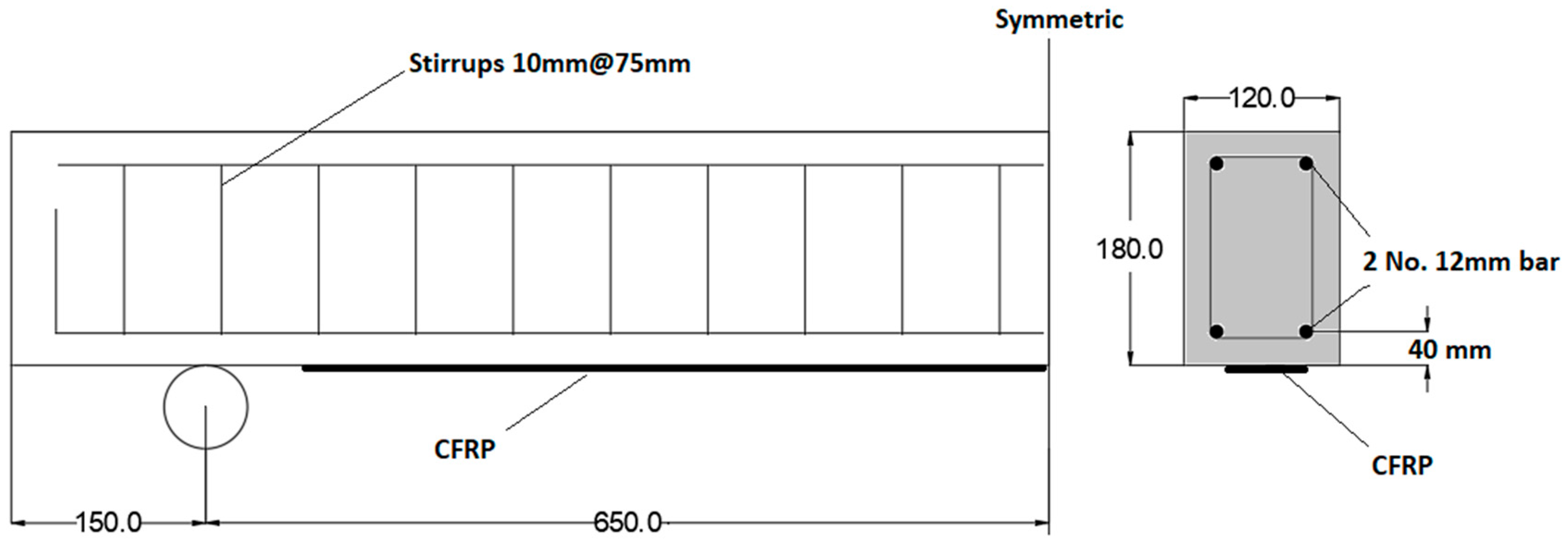
2.1. Specimens Details

The experimental work was conducted by fabricating seven RC beams with different strengthening techniques tested in two stages, five beams in the first stage and two beams in the second stage. The dimensions of the beams were 180 mm height × 120 mm wide × 1600 mm length, as shown in Figure 1. The first stage included five beams: the first beam was the reference; the second beam was strengthened with the external bonding over the transverse grooves (EBROTG) method; the third and fourth specimens were strengthened with the EBRITG method; and the fifth beam had a hybrid technique, including one layer of inside grooves and another layer of over grooves. The dimensions of the grooves were an 8 mm width and a 15 mm depth. In the second stage, to avoid the separation of the concrete covers, the bottom concrete covers of the two beams, B6 and B7, were anchored using steel bars penetrated inside holes that were 100 mm in depth, 10 mm in diameter, and each spaced 300 mm apart. The holes were filled with epoxy, and the bars were inserted inside the holes. After this process, the beams were strengthened with the hybrid system, one layer inside grooves for both beams and then the over-grooves layers, one for B6 and two for B7. The CFRP fabric used for the strengthening was 0.219 mm in thickness and 60 mm in width. The specimen details are illustrated in Table 1.

2.2. Materials Properties

In order to achieve the targeted compressive strength of 40 Mpa for the concrete specimens, the curing was implemented for 28 days. The compressive strength was determined using cylindrical tests of dimensions 200 × 100 mm according to ASTM C39/39M-18 [48]. The CFRP composite was supplied by the Mapei chemical production company [49]. The product name is MapeWrap C UNI-AX 400. The tensile strength of the CFRP was measured according to ASTM: D3039 [50] and confirmed with the mechanical properties provided by the manufacturer data sheet. The mechanical characteristics of the CFRP, concrete, and adhesive are illustrated in Table 2, Table 3, and Table 4, respectively.

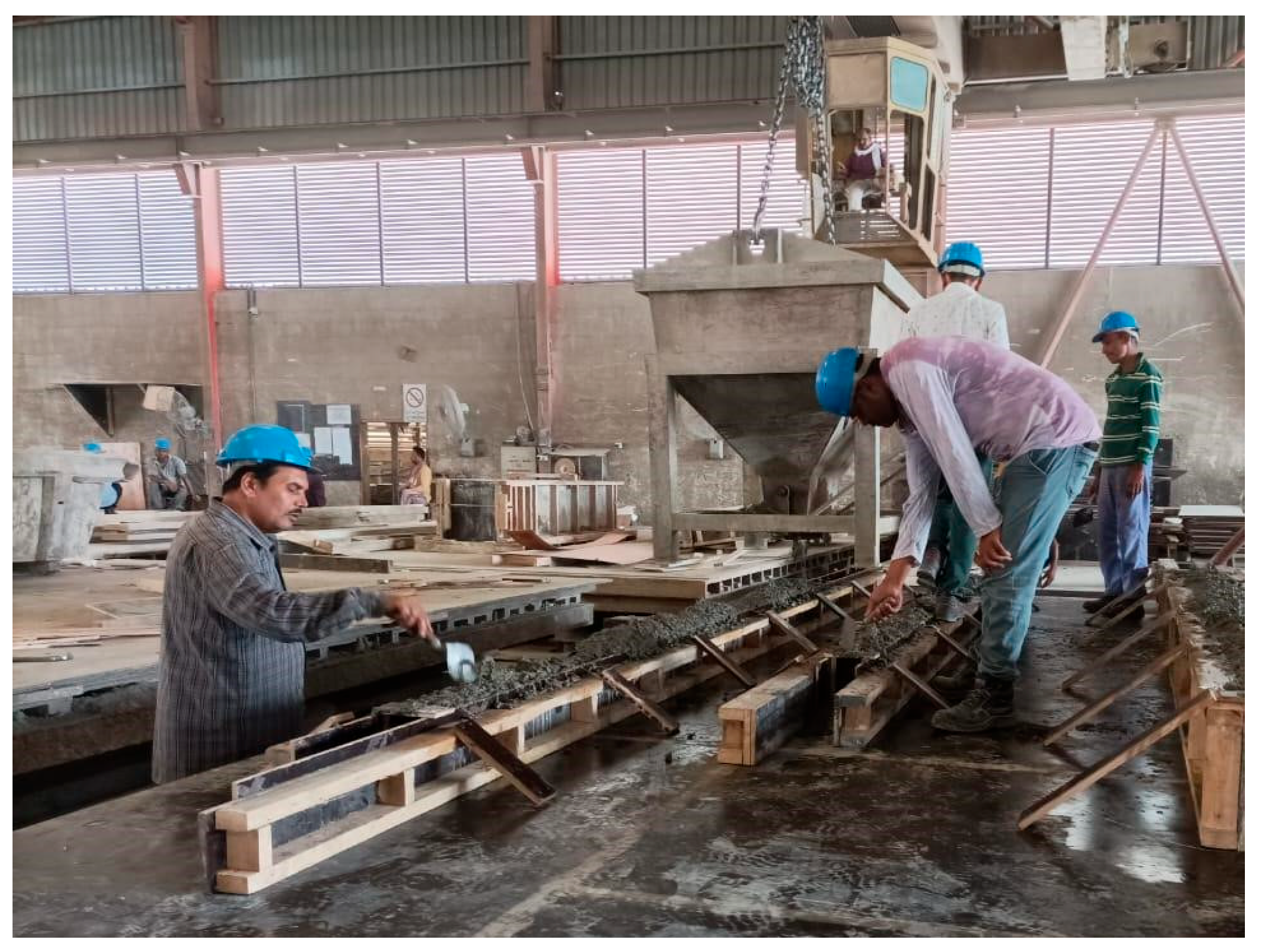
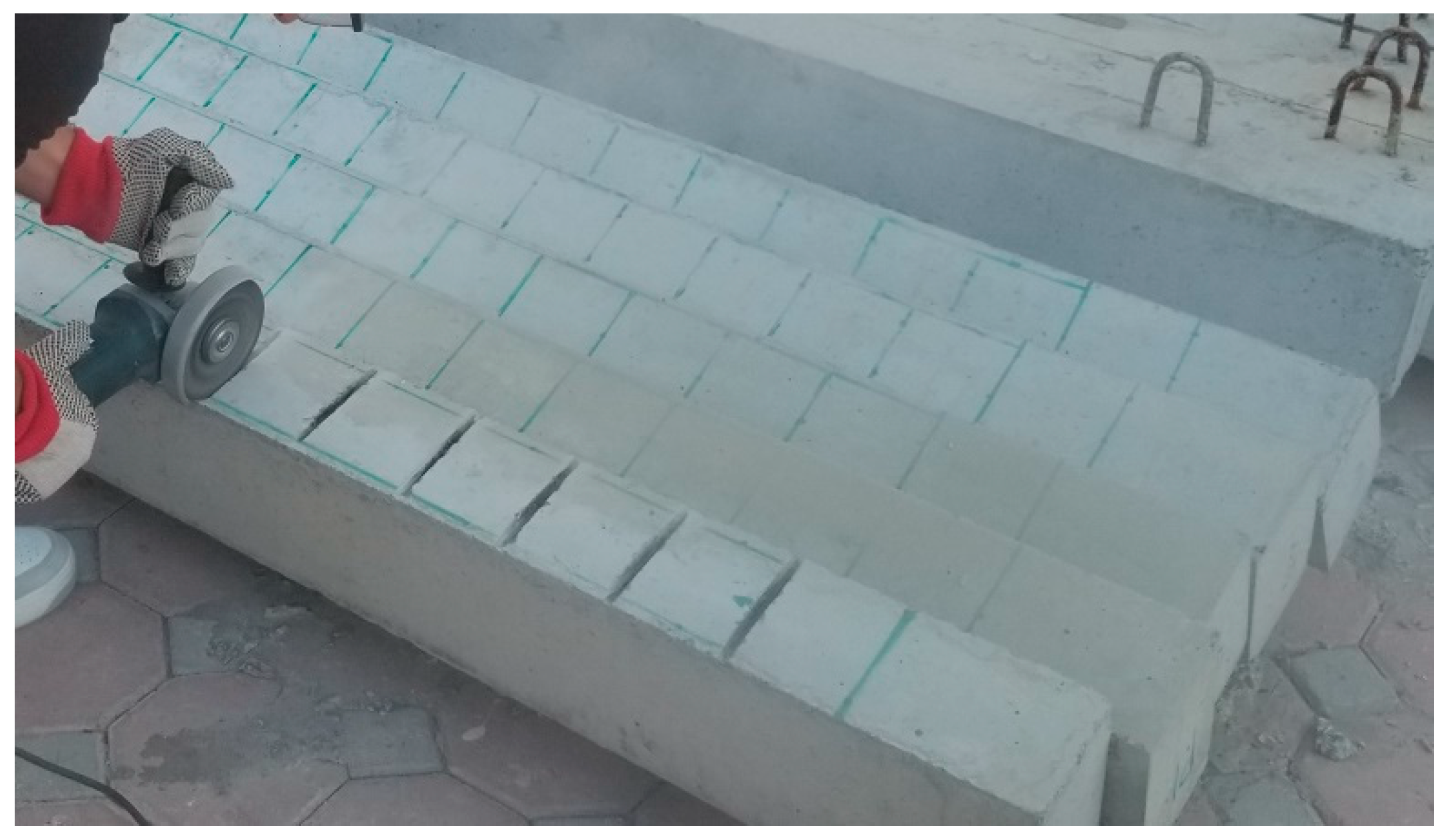
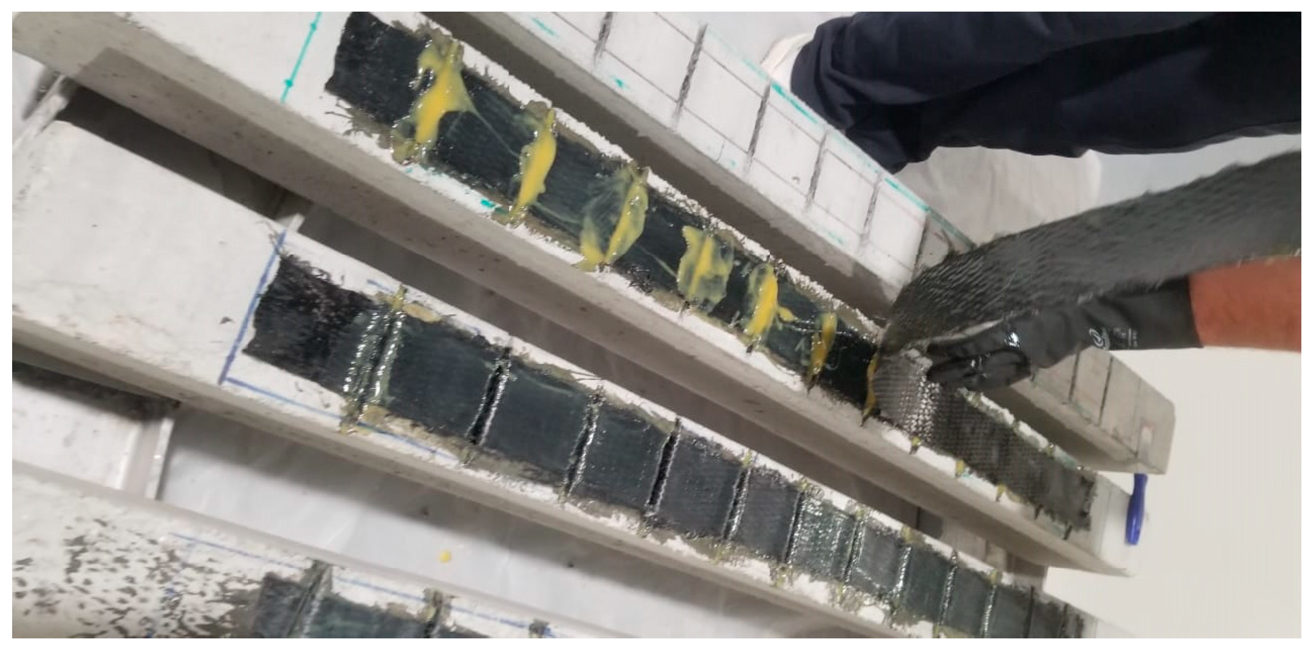
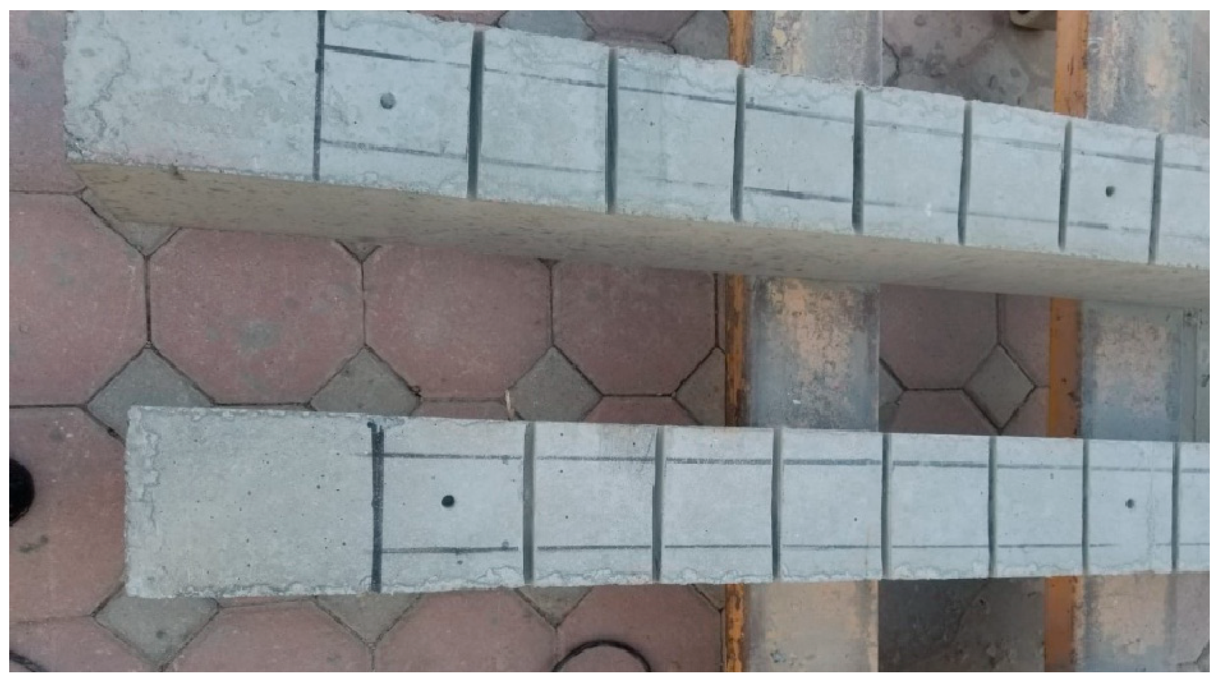
2.3. Specimen Fabrication and Strengthening

The concrete specimens were fabricated in a precast concrete factory to ensure accuracy and quality control for the casting and curing process (Figure 2). The reinforcing preparations of specimens with the CFRP started after 28 days of curing to ensure achieving the full concrete properties. The location of the grooves was marked on the soffit of the beam in each 100 mm space, and the grooves were cut using an electric grinder and extended 10 mm in each side out of the required strengthening width (60 mm) to ensure obtaining the same groove depth within this width (Figure 3).
After cleaning the surface from dust using air pressure, the adhesive was applied to the concrete surface, and the CFRP was impregnated using a roller according to the manufacturer recommendations. In the first stage, five beams were strengthened by different methods: over grooves, inside grooves, and the hybrid system. The CFRP was laid over the surface after filling the grooves with epoxy (EBROG) reinforcement and laid inside the grooves for (EBRIG) method. In the hybrid strengthening method, the first layer of the CFRP fabric was inserted inside the grooves, and then the second layer was externally laid over the first layer inside the grooves, as presented in Figure 4.
In the second stage, the two beams were strengthened with the hybrid system after anchoring the concrete cover at the beam soffit to enhance the strength against the separation of the concrete cover. The anchors were implemented by drilling three holes with a diameter of 10 mm and a depth 100 mm spaced at 600 mm (one at midspan and two at the ends) (Figure 5). The holes were filled with an epoxy adhesive (Mapefix VE SF) supplied by Mapei construction chemicals company [49], and the steel bars with an 8 mm diameter were inserted into the holes. All specimens were cured for two weeks before conducting the test.
The strain values were recorded in the CFRP using four strain gauges installed along one half of the beams. The type of strain gauges used in the test was TML, provided by Japan. The gauge factor was 2.11 (±1%) of the recorded strain values using a strain acquisition system (1/2 bridge) calibrated to synchronize the strain with load values. Figure 6 shows the strain gauges instrumented on the specimens.

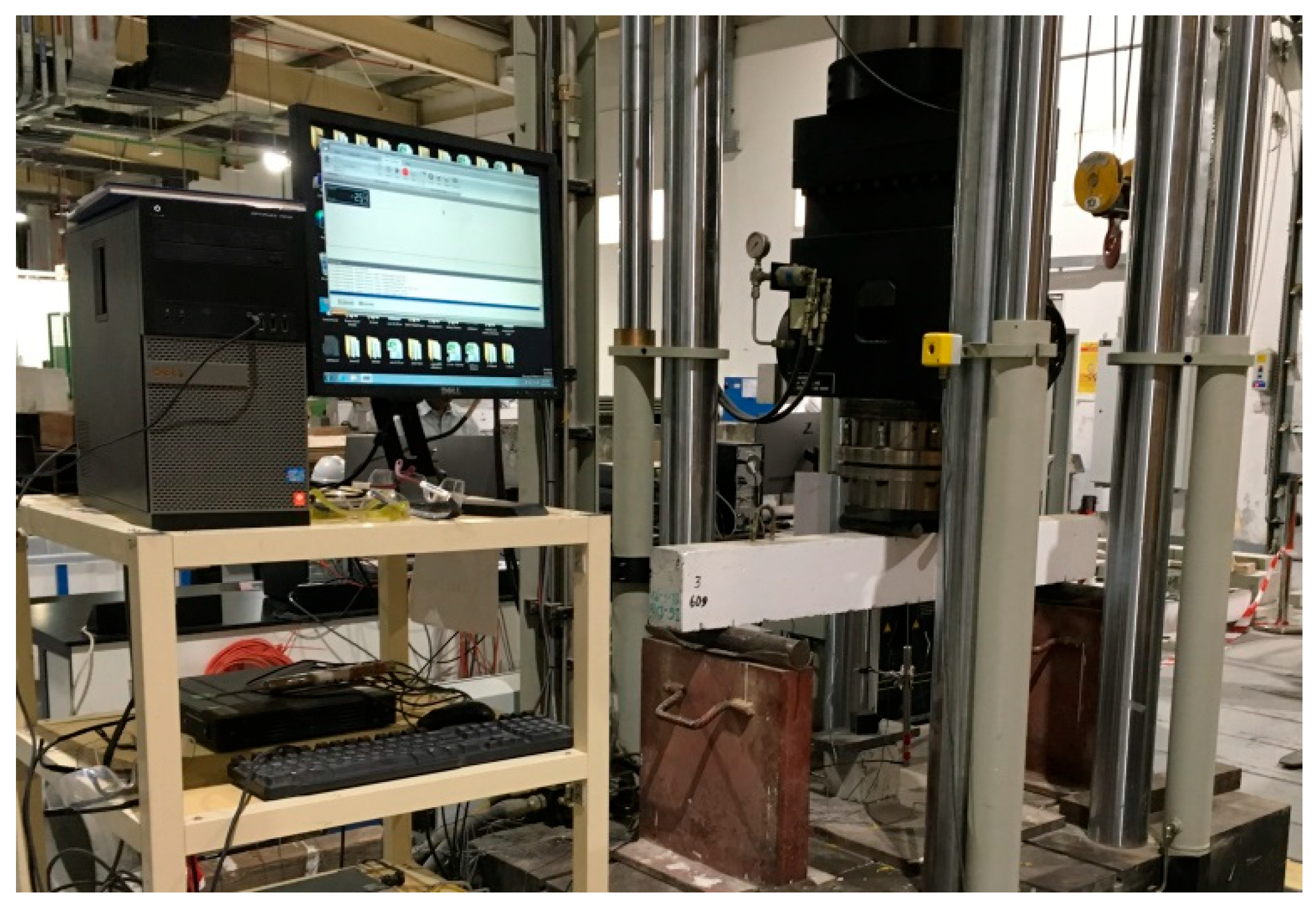
2.4. Test Configuration and Setup

The flexural testing method was implemented for all specimens using a 4-point load setup. The load was applied at two points on top of the beams with a shear span of 550 mm. The test was conducted in the structural laboratory of the American University of Sharjah using a 1200 kN Instron universal testing machine (Instron, Norwood, MA, USA). The loading increment on the beams was implemented using the displacement control method. The strain gauges were connected to the data logger, and two LVDTs were fixed to measure the displacement at the mid-span of the beams. The LVDTs were calibrated prior to the test to ensure accurate results. The testing setup on the testing machine is shown in Figure 7.

3. Experimental Results and Discussion

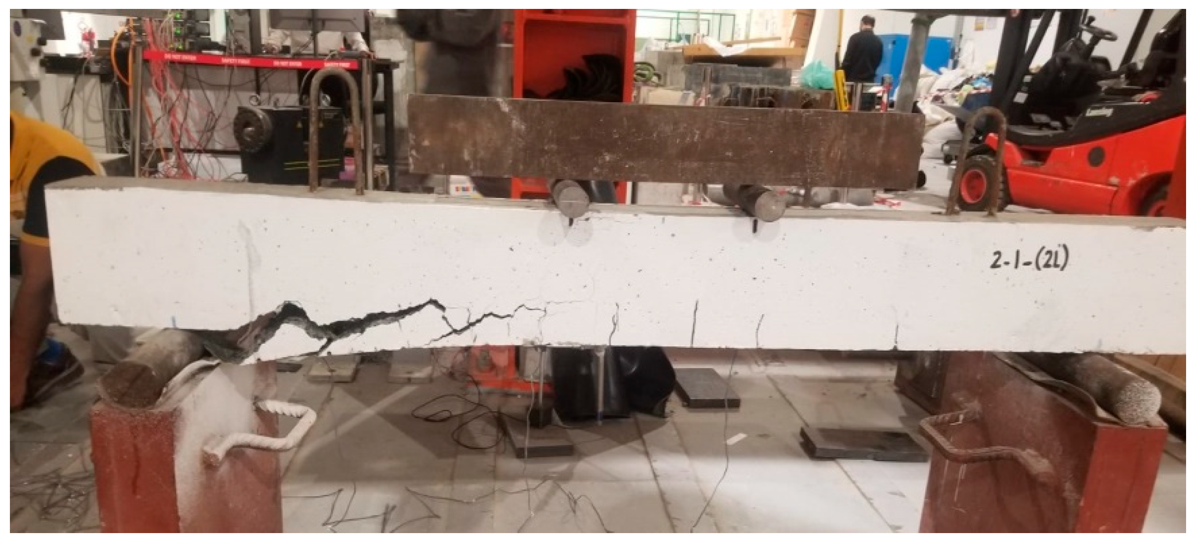
3.1. Load Capacity and Failure Modes
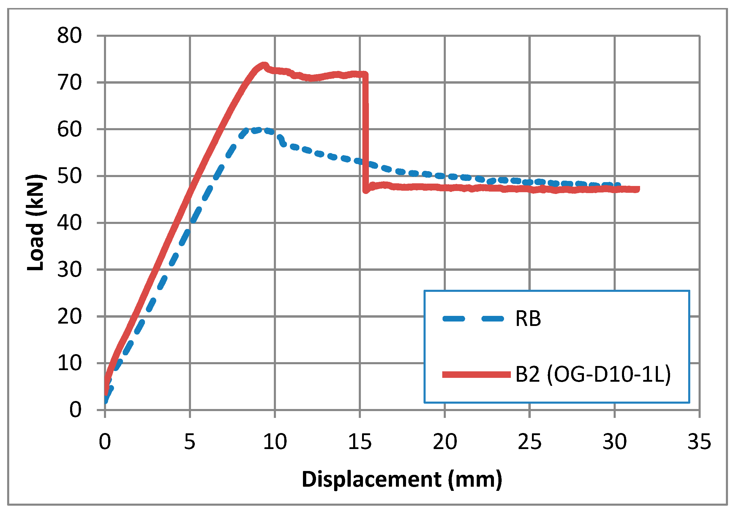
3.1.1. B2 Specimen

The ultimate load capacity and mode of failure of the beams can reflect the efficiency of bonding between the CFRP and the concrete surface according to the strengthening method. The conventional failure in the externally bonding over groove (EBROG) method for beam B2 was the delamination of the CFRP at the end of the fiber propagating to the midspan, as shown in Figure 8. The specimen achieved an ultimate load capacity of 73.76 kN, indicating a 22% increase compared to that of 60.4 kN recorded by the reference beam (B1), as illustrated in the load versus displacement curve in Figure 9.

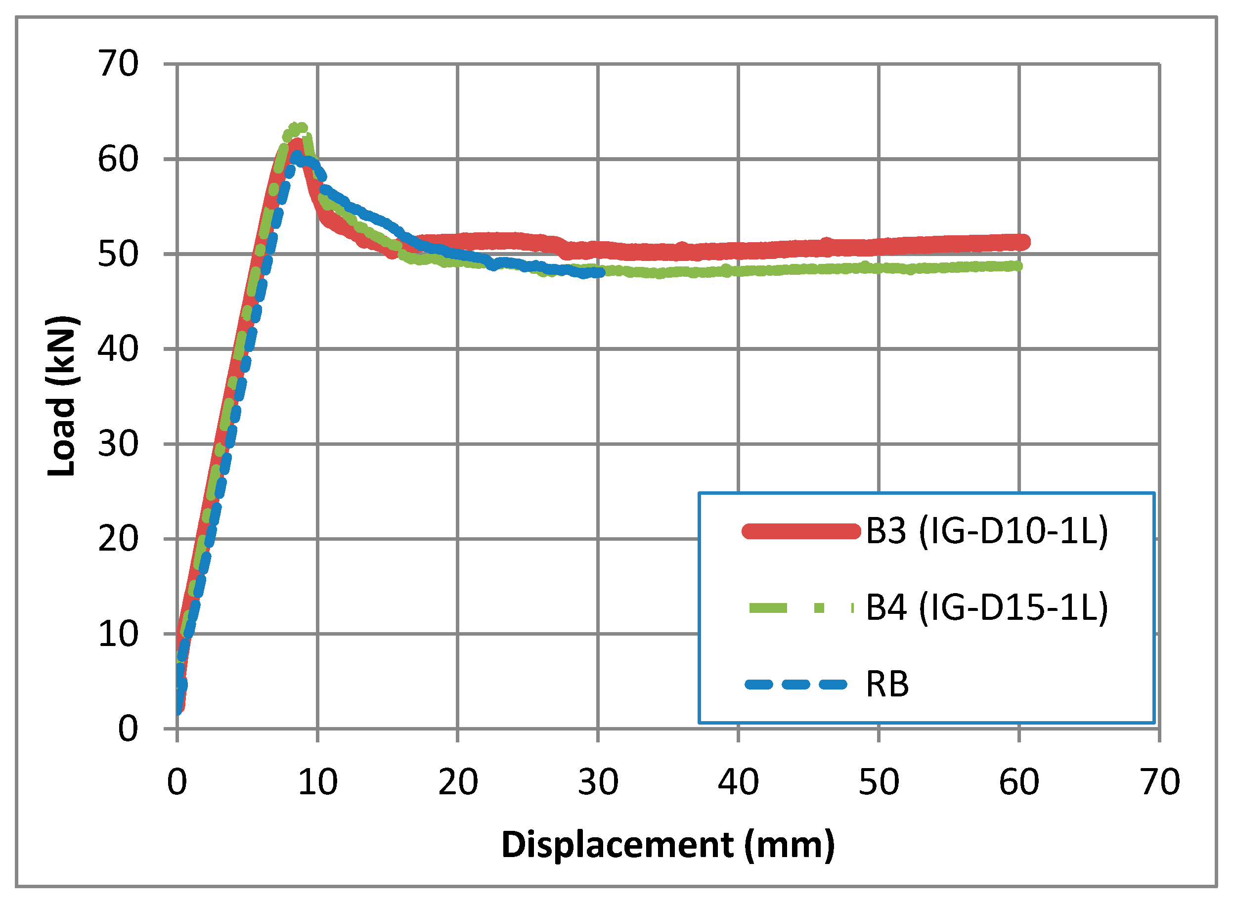
3.1.2. B3 and B4 Specimens
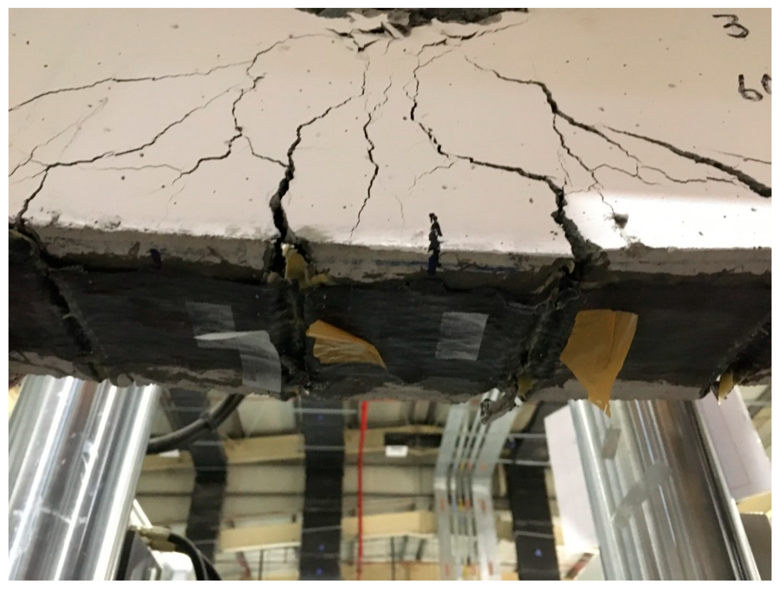
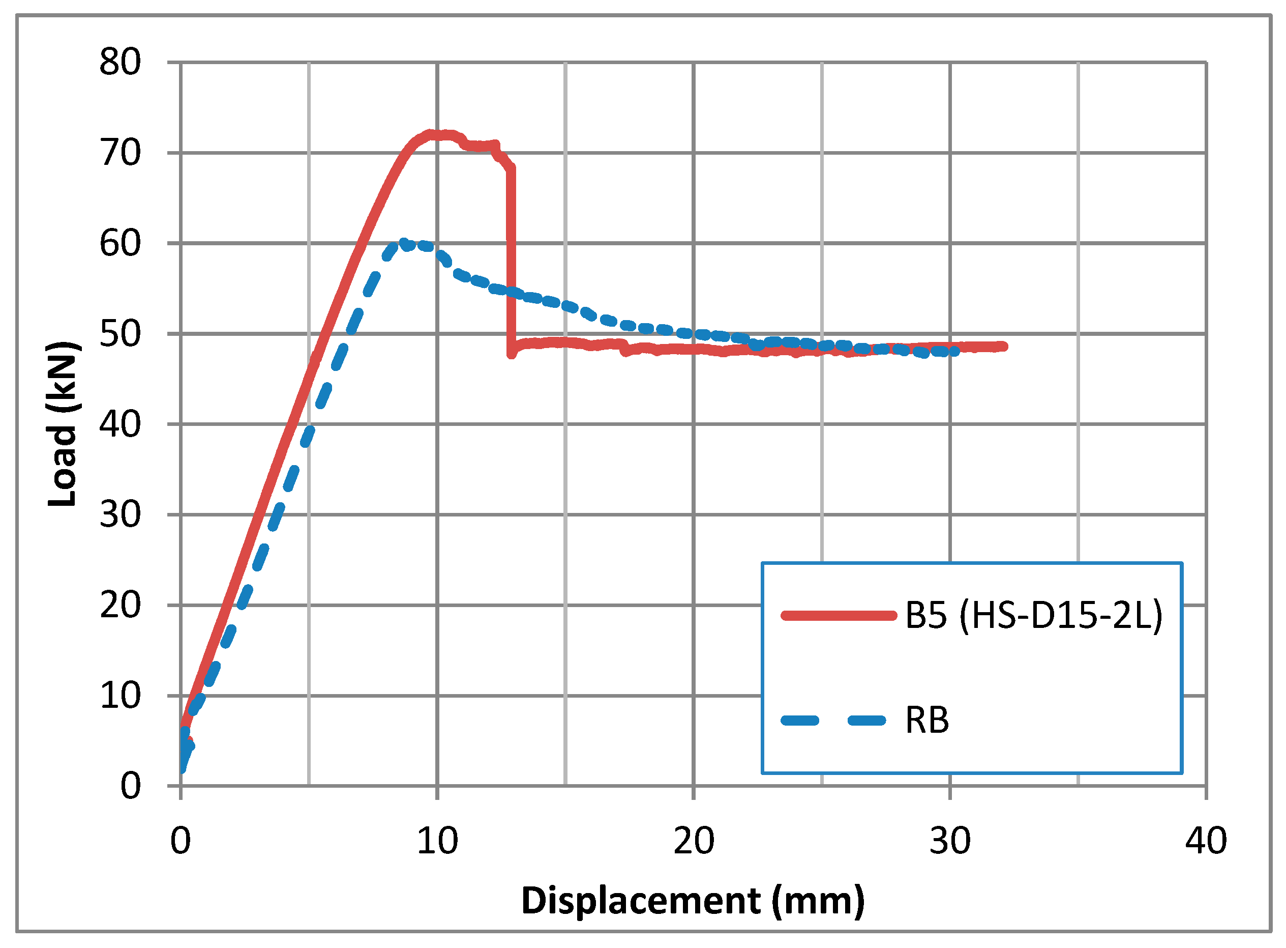
The specimen B3 with the CFRP bonded inside grooves (EBRIG) method exhibited a similar behavior to the reference specimen. The ultimate capacity of this specimen was 61.35 kN. Excluding the relative potential effect of epoxy-filling quality in grooves, this result can mainly be attributed to the discontinuity of the fiber reinforcement at the groove zone that inhibits resisting the tension forces at the beam soffit, causing a propagation of cracks at the grooves. Increasing the groove depth to 15 mm in B4 showed insignificant improvement in the load capacity with 65.35 kN, as presented in the load–displacement curves in Figure 10. The mode of failure was similar to that of B3, as presented in Figure 11.

3.1.3. B5 Specimen

Utilizing a hybrid system by combining the externally bonded CFRP over-the-groove layer laid over the inside-groove layer allows us to overcome the defect in each individual layer and enables transferring the tension stresses at the beam soffit. The inside-groove layer will provide anchorage for the CFRP against delamination, and the top over-groove layer will provide continuity to transfer the tension forces along the beam soffit. However, although inhibiting the delamination of fiber at the ends, the test results of specimen B5 with the hybrid strengthening technique showed premature failure due to separation of the concrete cover. This type of failure occurs due to increasing the stuffiness at the bonding zone with stress concentration at interfaces, causing a horizontal propagation of flexural cracks at the ends of the beam, which is similarly observed in the NSM-strengthening techniques using the epoxy adhesive [19,21]. The recorded ultimate load of the specimen was 72 kN, as shown in Figure 12, in comparison with the reference beam, and the failure mode with separation of concrete cover is exhibited in Figure 13.

3.1.4. B6 and B7 Specimens
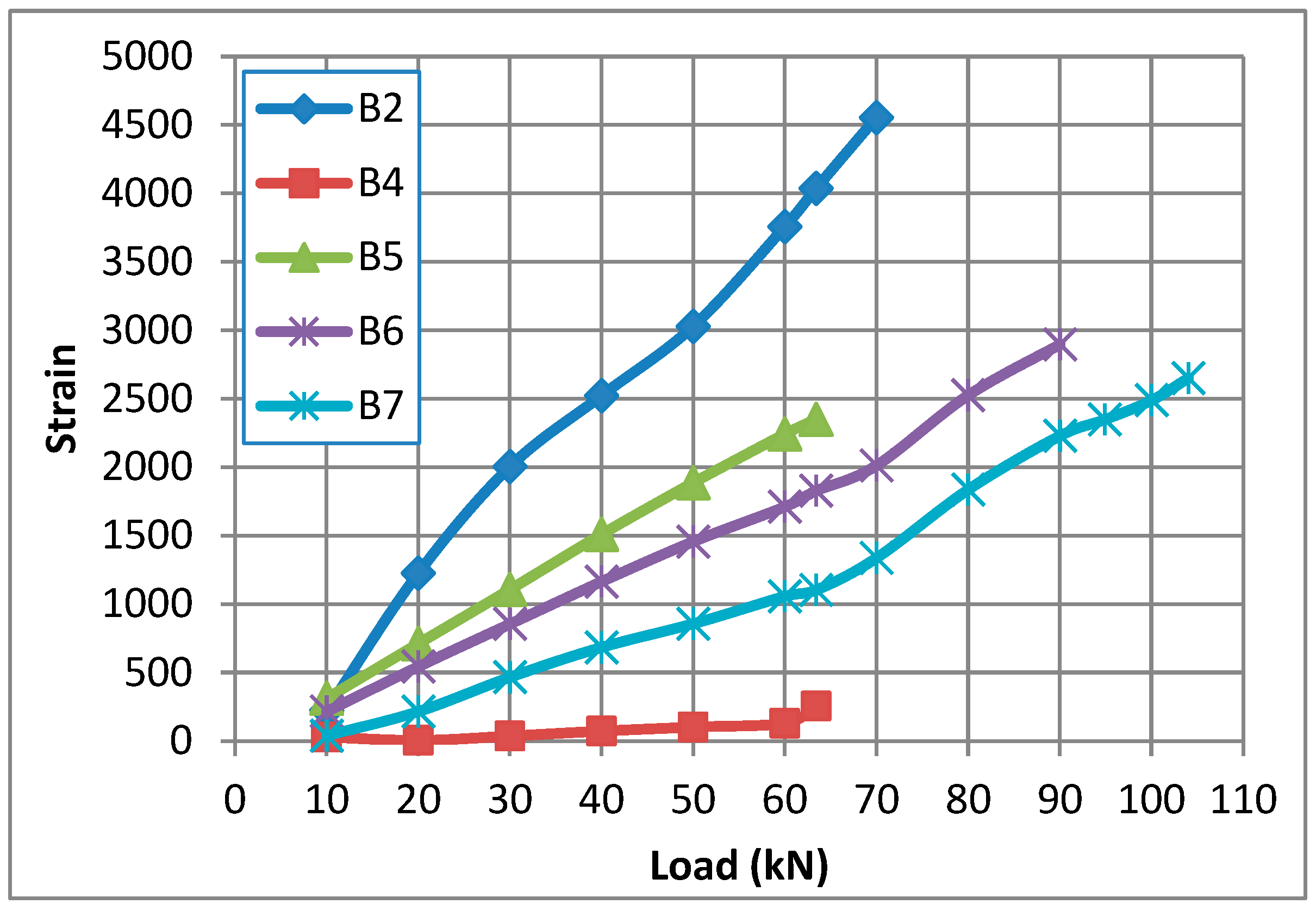
In the second stage, as the concrete cover was anchored, the test results showed a significant increase in load capacity. The specimen B6 with two layers exhibited an ultimate load of 94.93 kN with a 57% increase compared to the reference beam. Adding an additional layer in specimen B7 raised the load capacity to 72.5% by achieving an ultimate load of 104.27 kN. Figure 14 illustrates the load–displacement curves for B6 and B7 in comparison with B2 and RB. This improvement is higher than that achieved by NSM-strengthening techniques, where 50% increase has been achieved [19]. The mode of failure was similar for both specimens B6 and B7, as shown in Figure 15. The occurrence of failure by the separation of the concrete cover indicates the efficiency of the hybrid strengthening technique by inhibiting the premature delamination of fiber from the concrete surface, and increasing the load capacity can be significantly achieved by increasing the anchorage points for the bottom concrete cover or using the U-wrap of the CFRP. The test results of all specimens are illustrated in Table 5.

3.2. Strain Values

The strain variation at the mid-span for the beams B2, B4, B5, B6, and B7 is indicated in Figure 16. It can be observed that the evolution of strain in B4 (EBRIG) is very low, indicating a very low contribution of CFRP in strength due to the discontinuity of fiber at the bonding surface. In B2 (EBROG), a significant contribution of fiber in strength is observed. In B6 and B7, a lower strain value was recorded at the same load in B7 compared to B6, which indicates a higher stiffness due to the contribution of increasing the number of layers of CFRP to the load strength.

4. Conclusions

This study evaluated the performance of RC beams strengthened using EBRIG, EBROG, and the hybrid system, yielding the following conclusions:
  • The EBROG method exhibited CFRP delamination initiating at the fiber end and propagating to the mid-span. The ultimate load capacity reached 73.76 kN, a 22% increase over the reference beam (60.4 kN).
  • The EBRIG method showed minimal strength improvement (61.35 kN), attributed to the fiber discontinuity at the grooves, which disrupted the tension resistance and promoted crack propagation.
  • The hybrid system (EBRIG + EBROG) achieved a modest load increase (72 kN) due to a premature concrete cover separation.
  • Anchoring the concrete cover in the hybrid system significantly enhanced the performance: two layers (one EBRIG + one EBROG) increased in capacity by 57% (94 kN), while three layers (one EBRIG + two EBROG) achieved a 72.5% increase (104.27 kN).
  • The strain evolution analysis confirmed the CFRP’s contribution to the stiffness and load capacity, with the bonding-zone effectiveness improving alongside the layer count.

Author Contributions

Conceptualization, A.H.A.-A.; Methodology, A.H.A.-A.; Validation, A.H.A.-A. and A.K.A.-T.; Formal analysis, A.H.A.-A.; Resources, A.H.A.-A. and A.K.A.-T.; Writing—original draft, A.H.A.-A.; Writing—review and editing, A.H.A.-A. and A.K.A.-T.; Funding acquisition, A.K.A.-T. All authors have read and agreed to the published version of the manuscript.

Funding

This research received no external fund.

Data Availability Statement

The original contributions presented in the study are included in the article; further inquiries can be directed to the corresponding author.

Acknowledgments

We would like to express our great appreciation and acknowledgement to the civil engineering department at the American University of Sharjah and the Emirate Stones Company of precast concrete for their technical support during the research period.

Conflicts of Interest

The authors declare that they have no known competing financial interests or personal relationships that could have appeared to influence the work reported in this paper.

References

  1. Meier, U. Strengthening of structures using carbon fibre/epoxy composites. Constr. Build. Mater. 1995, 9, 341–351. [Google Scholar] [CrossRef]
  2. Yao, J.; Teng, J. Plate end debonding in FRP-plated RC beams—I: Experiments. Eng. Struct. 2007, 29, 2457–2471. [Google Scholar] [CrossRef]
  3. Tajmir-Riahi, A.; Moshiri, N.; Mostofinejad, D. Inquiry into bond behavior of CFRP sheets to concrete exposed to elevated temperatures–Experimental & analytical evaluation. Compos. Part B Eng. 2019, 173, 106897. [Google Scholar]
  4. Gao, P.; Gu, X.; Mosallam, A.S. Flexural behavior of preloaded reinforced concrete beams strengthened by prestressed CFRP laminates. Compos. Struct. 2016, 157, 33–50. [Google Scholar] [CrossRef]
  5. Guipeng, C.; Yanlie, W.; Shutong, Y. Elliptical FRP–concrete–steel double-skin tubular columns under cyclic compression: Fundamental characteristics and modeling. Eng. Struct. 2025, 326, 119517. [Google Scholar]
  6. Martinelli, E.; Hosseini, A.; Ghafoori, E.; Motavalli, M. Behavior of prestressed CFRP plates bonded to steel substrate: Numerical modeling and experimental validation. Compos. Struct. 2019, 207, 974–984. [Google Scholar] [CrossRef]
  7. Hosseini, A.; Nussbaumer, A.; Motavalli, M.; Zhao, X.-L.; Ghafoori, E. Mixed mode I/II fatigue crack arrest in steel members using prestressed CFRP reinforcement. Int. J. Fatigue 2019, 127, 345–361. [Google Scholar] [CrossRef]
  8. Mosallam, A.; Banerjee, S. Enhancement in in-plane shear capacity of unreinforced masonry (URM) walls strengthened with fiber reinforced polymer composites. Compos. Part B Eng. 2011, 42, 1657–1670. [Google Scholar] [CrossRef]
  9. Hosseini, A.; Mostofinejad, D.; Emami, M. Influence of bonding technique on bond behavior of CFRP-to-clay brick masonry joints: Experimental study using particle image velocimetry (PIV). Int. J. Adhes. Adhes. 2015, 59, 27–39. [Google Scholar] [CrossRef]
  10. Ali, A.; Abdalla, J.; Hawileh, R.; Galal, K. CFRP mechanical anchorage for externally strengthened RC beams under flexure. Phys. Procedia 2014, 55, 10–16. [Google Scholar] [CrossRef]
  11. Yu, P.; Silva, P.F.; Nanni, A. Description of a mechanical device for prestressing of carbon fiber-reinforced polymer sheets-Part I. ACI Struct. J. 2008, 105, 3–10. [Google Scholar]
  12. Michels, J.; Martinelli, E.; Czaderski, C.; Motavalli, M. Prestressed CFRP strips with gradient anchorage for structural concrete retrofitting: Experiments and numerical modeling. Polymers 2014, 6, 114–131. [Google Scholar] [CrossRef]
  13. Pham, H.B.; Al-Mahaidi, R. Prediction models for debonding failure loads of carbon fiber reinforced polymer retrofitted reinforced concrete beams. J. Compos. Constr. 2006, 10, 48–59. [Google Scholar] [CrossRef]
  14. Kim, Y.J.; Wight, R.G.; Green, M.F. Flexural strengthening of RC beams with prestressed CFRP sheets: Development of nonmetallic anchor systems. J. Compos. Constr. 2008, 12, 35–43. [Google Scholar] [CrossRef]
  15. Michels, J.; Sena-Cruz, J.; Czaderski, C.; Motavalli, M. Structural strengthening with prestressed CFRP strips with gradient anchorage. J. Compos. Constr. 2013, 17, 651–661. [Google Scholar] [CrossRef]
  16. Bilotta, A.; Ceroni, F.; Di Ludovico, M.; Nigro, E.; Pecce, M.; Manfredi, G. Bond efficiency of EBR and NSM FRP systems for strengthening concrete members. J. Compos. Constr. 2011, 15, 757–772. [Google Scholar] [CrossRef]
  17. Hajihashemi, A.; Mostofinejad, D.; Azhari, M. Investigation of RC beams strengthened with prestressed NSM CFRP laminates. J. Compos. Constr. 2011, 15, 887–895. [Google Scholar] [CrossRef]
  18. Nordin, H.; Täljsten, B. Prestressed near surface mounted reinforcement (NSMR) for strengthening concrete beams. In FRP Composites in Civil Engineering-CICE 2004: Proceedings of the 2nd International Conference on FRP Composites in Civil Engineering—CICE 2004, Adelaide, Australia, 8–10 December 2004; CRC Press: Boca Raton, FL, USA, 2002; p. 447. [Google Scholar]
  19. Al-Abdwais, H.; Al-Mahaidi, R. Experimental and finite element analysis of flexural performance of RC beams retrofitted using near-surface mounted with CFRP composites and cement adhesive. Eng. Struct. 2021, 241, 112429. [Google Scholar] [CrossRef]
  20. AL-Abdwais, H.; Al-mahaidi, R. Performance of NSM CFRP strengthened concrete using modified cement-based adhesive at elevated temperature. Constr. Build. Mater. 2017, 132, 296–302. [Google Scholar] [CrossRef]
  21. Al-Abdwais, H.; Al-Mahaidi, R. Performance of reinforced concrete beams strengthened with NSM CFR Composites for flexure using cement-based adhesives. Struct. J. 2020, 27, 1446–1457. [Google Scholar] [CrossRef]
  22. Mostofinejad, D.; Mahmoudabadi, E. Grooving as alternative method of surface preparation to postpone debonding of FRP laminates in concrete beams. J. Compos. Constr. 2010, 14, 804–811. [Google Scholar] [CrossRef]
  23. Mostofinejad, D.; Shameli, S.M.; Hosseini, A. EBROG and EBRIG methods for strengthening of RC beams by FRP sheets. Eur. J. Environ. Civ. Eng. 2014, 18, 652–668. [Google Scholar] [CrossRef]
  24. Moshiri, N.; Tajmir-Riahi, A.; Mostofinejad, D.; Czaderski, C.; Motavalli, M. Experimental and analytical study on CFRP strips-to-concrete bonded joints using EBROG method. Compos. Part B Eng. 2019, 158, 437–447. [Google Scholar] [CrossRef]
  25. Tajmir-Riahi, A.; Moshiri, N.; Mostofinejad, D. Bond mechanism of EBROG method using a single groove to attach CFRP sheets on concrete. Constr. Build. Mater. 2019, 197, 693–704. [Google Scholar] [CrossRef]
  26. Shomali, A.; Mostofinejad, D.; Esfahani, M.R. Experimental and numerical investigation of shear performance of RC beams strengthened with FRP using grooving method. J. Build. Eng. 2020, 31, 101409. [Google Scholar] [CrossRef]
  27. Mostofinejad, D.; Hosseini, S.A.; Razavi, S.B. Influence of different bonding and wrapping techniques on performance of beams strengthened in shear using CFRP reinforcement. Constr. Build. Mater. 2016, 116, 310–320. [Google Scholar] [CrossRef]
  28. Czaderski, C.; Moshiri, N.; Hosseini, A.; Mostofinejad, D.; Motavalli, M. EBROG technique to enhance the bond performance of CFRP strips to concrete substrate. In Proceedings of the SMAR 2019-Fifth Conference on Smart Monitoring, Assessment and Rehabilitation of Civil Structures, Berlin, Germany, 27–29 August 2019. [Google Scholar]
  29. Moshiri, N.; Hosseini, A.; Mostofinejad, D. Strengthening of RC columns by longitudinal CFRP sheets: Effect of strengthening technique. Constr. Build. Mater. 2015, 79, 318–325. [Google Scholar] [CrossRef]
  30. Mostofinejad, D.; Moshiri, N. Compressive strength of CFRP composites used for strengthening of RC columns: Comparative evaluation of EBR and grooving methods. J. Compos. Constr. 2014, 19, 04014079. [Google Scholar] [CrossRef]
  31. NoroozOlyaee, M.; Mostofinejad, D. Slenderness Effects in Circular RC Columns Strengthened with CFRP Sheets Using Different External Bonding Techniques. J. Compos. Constr. 2019, 23, 04018068. [Google Scholar] [CrossRef]
  32. Ilia, E.; Mostofinejad, D. Seismic retrofit of reinforced concrete strong beam–weak column joints using EBROG method combined with CFRP anchorage system. Eng. Struct. 2019, 194, 300–319. [Google Scholar] [CrossRef]
  33. Tajmir-Riahi, A.; Mostofinejad, D.; Moshiri, N. Bond resistance of a single groove in EBROG method to attach CFRP sheets on concrete. In Proceedings of the Ninth International Conference on Fibre-Reinforced Polymer (FRP) Composites in Civil Engineering (CICE 2018), Paris, France, 17–19 July 2018; pp. 368–373. [Google Scholar]
  34. Hosseini, A.; Mostofinejad, D. Experimental investigation into bond behavior of CFRP sheets attached to concrete using EBR and EBROG techniques. Compos. Part B Eng. 2013, 51, 130–139. [Google Scholar] [CrossRef]
  35. Moshiri, N.; Mostofinejad, D.; Tajmir-Riahi, A. Bond behavior of pre-cured CFRP strips to concrete using externally bonded reinforcement on groove (EBROG) method. In Proceedings of the Ninth International Conference on Fibre-Reinforced Polymer (FRP) Composites in Civil Engineering (CICE 2018), Paris, France, 17–19 July 2018; pp. 361–367. [Google Scholar]
  36. Moshiri, N.; Czaderski, C.; Mostofinejad, D.; Motavalli, M. Bond strength of prestressed CFRP strips to concrete substrate: Comparative evaluation of EBR and EBROG methods. In Proceedings of the SMAR 2019-Fifth Conference on Smart Monitoring, Assessment and Rehabilitation of Civil Structures, Berlin, Germany, 27–29 August 2019. [Google Scholar]
  37. Mostofinejad, D.; Mohammadi, M. Effect of Freeze–Thaw Cycles on FRP-Concrete Bond Strength in EBR and EBROG Systems. J. Compos. Constr. 2020, 24, 04020009. [Google Scholar] [CrossRef]
  38. Tajmir-Riahi, A.; Moshiri, N.; Mostofinejad, D. EBROG method to strengthen heat751damaged concrete with CFRP sheets. In Proceedings of the SMAR 2019-Fifth Conference on Smart Monitoring, Assessment and Rehabilitation of Civil Structures, Berlin, Germany, 27–29 August 2019. [Google Scholar]
  39. Moghaddas, A.; Mostofinejad, D. Empirical FRP-Concrete Bond Strength Model for Externally Bonded Reinforcement on Grooves. J. Compos. Constr. 2018, 23, 04018080. [Google Scholar] [CrossRef]
  40. Heydari Mofrad, M.; Mostofinejad, D.; Hosseini, A. A generic non-linear bond-slip model for CFRP composites bonded to concrete substrate using EBR and EBROG techniques. Compos. Struct. 2019, 220, 31–44. [Google Scholar] [CrossRef]
  41. Tajmir-Riahi, A.; Moshiri, N.; Czaderski, C.; Mostofinejad, D. Effect of the EBROG method on strip-to-concrete bond behavior. Constr. Build. Mater. 2019, 220, 701–711. [Google Scholar] [CrossRef]
  42. Michels, J.; Zile, E.; Czaderski, C.; Motavalli, M. Debonding failure 761 mechanisms in prestressed CFRP/epoxy/concrete connections. Eng. Fract. Mech. 2014, 132, 16–37. [Google Scholar] [CrossRef]
  43. Moshiri, N.; Czadersk, C. Flexural strengthening of RC slabs with non prestressed and prestressed CFRP strips using EBROG method. Compos. Part B Eng. 2020, 201, 108359. [Google Scholar] [CrossRef]
  44. Moghaddas, A.; Mostofinejad, D. An empirical FRP-concrete bond-slip model for externally-bonded reinforcement on grooves. Constr. Build. Mater. 2021, 281, 122575. [Google Scholar] [CrossRef]
  45. Mostofinejad, D.; Shameli, S.M. Externally bonded reinforcement in grooves (EBRIG) technique to postpone debonding of FRP sheets in strengthened concrete beams. Constr. Build. Mater. 2013, 38, 751–758. [Google Scholar] [CrossRef]
  46. Abdel-Kareem, A.H.; Elprince, M.; Makhlouf, M.H. Structural performance of RC beams with openings shear strengthened by hybrid techniques (EBR/EBRIG). Eur. J. Environ. Civ. Eng. 2024, 28, 1637–1657. [Google Scholar] [CrossRef]
  47. Al-Abdwais, A.; Al-Tamimi, K. Evaluation of bonding properties between CFRP laminate and concrete using externally bonded reinforcement on transverse grooves (EBROTG) method. J. Compos. Sci. 2024, 8, 488. [Google Scholar] [CrossRef]
  48. ASTM C39/C39M-18; Standard Test Method for Compressive Strength of Cylindrical Concrete Specimens. ASTM International: West Conshohocken, PA, USA, 2017.
  49. Mapei Construction Chemical Production Company. UAE. Available online: https://www.mapei.com/ae/en/about-us/mapei-in-uae (accessed on 15 July 2024).
  50. ASTM D3039/D3039M-17; Standard Test Method for Tensile Properties of Polymer Matrix Composite Materials. ASTM International: West Conshohocken, PA, USA, 2017.
Figure 1. Geometrical and reinforcement details of the specimens.
Fibers 13 00093 g001
Figure 2. Specimen fabrication.
Fibers 13 00093 g002
Figure 3. Cutting grooves.
Fibers 13 00093 g003
Figure 4. Strengthening of specimens.
Fibers 13 00093 g004
Figure 5. Holes for anchoring of concrete cover.
Fibers 13 00093 g005
Figure 6. Cured specimens with strain gauges.
Fibers 13 00093 g006
Figure 7. Test setup of the specimens.
Fibers 13 00093 g007
Figure 8. Mode of failure of B2.
Fibers 13 00093 g008
Figure 9. Load–displacement curves of B2 and RB.
Fibers 13 00093 g009
Figure 10. Load–displacement plot of specimens B3, B4, and RB.
Fibers 13 00093 g010
Figure 11. Failure mode of B3.
Fibers 13 00093 g011
Figure 12. Load–displacement curves of B5 and RB.
Fibers 13 00093 g012
Figure 13. Failure mode of B5.
Fibers 13 00093 g013
Figure 14. Load versus displacement of B2, B6, B7, and RB.
Fibers 13 00093 g014
Figure 15. Failure mode of B6.
Fibers 13 00093 g015
Figure 16. Strain variation.
Fibers 13 00093 g016
Table 1. Specimen details.
Beam No.DesignationGroove Depth (mm)Groove Width (mm)Distance Between Grooves (mm)
B1RB---
B2OG-D10-iL--100
B3IG-D10-1L108100
B4IG-D15-1L108100
B5HS-D15-2L158100
B6HS-D15-2L(Anchor)158100
B7HS-D15-3L(Anchor)158100
R: Reference, OG: over groove, IG: inside groove, D: groove depth, L: layers, HS: hybrid system.
Table 2. Specifications of CFRP fabric [45].
MaterialThickness
(mm)
Tensile Strength (MPa)Modulus of Elasticity (GPa)Elongation at Break
(%)
CFRP fabric0.21949002522
Table 3. Concrete properties.
MaterialDimensions
(mm)
Compressive Strength (MPa)Tensile Strength (MPa)Modulus of Elasticity (MPa)
Concrete200 heights × 100 diameter423.6425,900
Table 4. Adhesive properties as per manufacturer data sheet [45].
AdhesiveCompressive Strength (MPa)Tensile Strength (MPa)Modulus of Elasticity (MPa)
MapeWrap-317040>3001
Table 5. Test results and mode of failure of the specimens.
Beam No.DesignationsGroove Depth (mm)Groove Width (mm)Ultimate Load (kN)Failure Mode
B1RB--60.42bending
B2OG-D10-iL10873.76Delamination at Fiber end
B3IG-D10-1L10861.35bending
B4IG-D15-1L15865.35bending
B5HS-D15-2L15872.00Separation of concrete cover
B6HS-D15-2L(Anchor)15894.93Separation of concrete cover
B7HS-D15-3L(Anchor)158104.27Separation of concrete cover
R: Reference, OG: over groove, IG: inside groove, D: groove depth, L: layers, HS: hybrid system.
Disclaimer/Publisher’s Note: The statements, opinions and data contained in all publications are solely those of the individual author(s) and contributor(s) and not of MDPI and/or the editor(s). MDPI and/or the editor(s) disclaim responsibility for any injury to people or property resulting from any ideas, methods, instructions or products referred to in the content.

