Article

Experimental Analysis of Low-Energy Impact Damage in Composite Material Airfoils

by
Ilse Jauregui Bogarin
1,
Virginia G. Angel
1,*,
Miriam Siqueiros Hernández
1,
Emmanuel Santiago Durazo Romero
1,
Hernán D. Magaña-Almaguer
2,
Lidia Esther Vargas Osuna
1 and
Benjamín González Vizcarra
3
1
Facultad de Ingeniería, Universidad Autónoma de Baja California, Mexicali 21280, Baja California, Mexico
2
IT de Mexicali, Tecnológico Nacional de México, Mexicali 21376, Baja California, Mexico
3
Facultad de Ciencias de la Ingeniería y Tecnología FCITEC, Unidad Valle de las Palmas, Tijuana 21500, Baja California, Mexico
*
Author to whom correspondence should be addressed.
Fibers 2025, 13(5), 67; https://doi.org/10.3390/fib13050067
Submission received: 7 March 2025 / Revised: 7 May 2025 / Accepted: 13 May 2025 / Published: 19 May 2025

Abstract

:

Highlights

What are the main findings?
  • Low-energy impacts caused matrix cracking and delamination in all specimens, while fiber–matrix debonding and matrix tearing were only observed in flat laminates, not in curved airfoil profiles.
  • Airfoil geometry influenced damage propagation; GOE777-IL showed higher impact resistance while SC(2)-0714 presented larger damage areas.
What is the implication of the main finding?
  • Conventional visual inspection may underestimate internal damage, highlighting the importance of advanced non-destructive techniques.
  • Results support the development of geometry-specific impact tolerance criteria for composite structures.

Abstract

The use of composite materials in aerospace structures has led to significant weight reductions and improved performance. However, their behavior under low-energy impact remains a critical concern due to the potential initiation of barely visible damage. This study investigates the crack initiation mechanisms in composite airfoil profiles subjected to low-energy impact, simulating real-world scenarios such as hail or bird strikes. Two types of airfoil profiles were fabricated using bidirectional carbon fiber reinforced polymer (CFRP) with epoxy resin and tested under ASTM D7136 impact conditions. Tensile tests following ASTM D3039 were conducted to assess post-impact mechanical behavior. The damage patterns were analyzed using high-resolution microscopy and non-destructive inspection techniques. Results revealed that damage severity and propagation depend on impact energy levels and airfoil geometry, with SC(2)-0714 exhibiting better impact resistance than GOE777-IL. Microscopic analysis confirmed that delamination initiated at 45° fiber orientations, expanding along interlaminar regions, while airfoil curvature influenced the impact energy dissipation.

1. Introduction

Polymer composites reinforced with carbon fiber (CFRP) have become increasingly relevant in advanced industries such as aerospace, automotive, marine engineering, and rail transportation, owing to their exceptional strength-to-weight and stiffness-to-weight ratios, as well as their high resistance to fatigue [1,2,3]. Given the widespread application of CFRP materials, understanding their mechanical behavior and failure phenomena is crucial for enhancing damage prediction models and improving the structural reliability of composite structures and other load-bearing components. H. Zhang et al. reveal that fracture initiation in CFRP composites is predominantly influenced by fiber volume fraction and orientation, with debonding at the fiber-matrix interface being the primary failure mechanism. The synchrotron micro-X-ray computed tomography (µXCT) analysis confirmed that high fiber volume fractions (>50%) and fiber orientations exceeding 70° contribute to accelerated crack propagation [4]. The study by Liu and Li examines the mode I interlaminar fracture behavior of CFRP multidirectional laminates, focusing on the effect of fiber orientation on delamination toughness. Using double cantilever beam (DCB) testing and X-ray microtomography, they found that multidirectional laminates exhibit lower crack initiation resistance but higher propagation toughness than unidirectional laminates. A cohesive zone model with variable fracture toughness provided more accurate delamination predictions, highlighting the critical role of fiber orientation in damage evolution [5].
The study by Duan et al. analyzes crack initiation and propagation in CFRP-strengthened RC beams under static and impact loading using digital image correlation (DIC). Results show that CFRP reduced crack width and length by up to 55.4% and 14.6% under static loads and 44.4% and 17.2% under impact conditions. CFRP also delayed crack initiation and slowed propagation rates by 20–40%, improving structural resilience. Under impact loading, the failure mode shifted from flexural to shear failure, highlighting the inertial effects on composite performance. These findings reinforce the role of fiber-reinforced composites in mitigating failure risks, providing insights into damage evolution in composite airfoil structures [6]. The findings by Lu et al. highlight the importance of fiber reinforcement in enhancing mechanical properties, particularly fracture resistance and load-bearing capacity. Similarly to CFRP airfoils, where fiber-matrix bonding influences impact resistance and damage propagation, this study demonstrates that well-bonded fiber-matrix interfaces improve tensile strength and energy absorption, which are critical factors in impact-resistant aerospace structures [7].
Jiang et al. investigated the strengthening mechanisms of carbon fiber-reinforced sand powder (CFRSP) composites, demonstrating that carbon fibers significantly enhance compressive strength, elastic modulus, and fracture resistance while modifying crack propagation behavior. They revealed that fiber bridging improves toughness and tensile-shear resistance, reducing premature failure. However, excessive fiber content led to weakened interfaces, affecting overall mechanical properties [8]. These findings align with structural composite applications, where fiber orientation and matrix interactions critically influence damage tolerance. In CFRP airfoils, similar mechanisms govern impact damage evolution, highlighting the importance of optimizing fiber architecture to enhance structural resilience and failure resistance. Li et al. explored the reinforcement of carbon fiber-reinforced polyimide (CFRP-PI) composites using vertically aligned carbon nanotubes (VA-CNTs) to enhance fracture toughness and fatigue resistance for high-temperature aerospace applications. Results show that VA-CNTs increased Mode I fracture toughness by 31%, SBS strength by 22%, and fatigue life by up to 13 times, shifting failure modes away from interlaminar regions. These findings highlight the role of nanoscale reinforcements in improving damage tolerance, offering insights into impact resistance in aerospace composites [9].
Mode I crack propagation in polydimethylsiloxane (PDMS)-short carbon fiber (CF) composites was analyzed by Hou et al. using experiments and numerical simulations [10]. Results show that carbon fibers enhance stiffness and toughening effects but also lead to interfacial debonding and increased Mullins effect, affecting energy dissipation. A cohesive zone model was implemented to simulate crack growth and fiber-matrix interactions, revealing that CF pinning, pull-out, and viscoelastic dissipation significantly influence damage resistance. These findings provide insights into composite failure mechanisms, offering a deeper understanding of energy dissipation and stress transfer, relevant to impact-induced damage [10]. Rojas Sanchez and Waas analyzed fatigue damage growth in cross-ply fiber-reinforced composites, tracking crack initiation and delamination propagation using DIC, infrared thermography, and CT. Results show that transverse cracks evolve into delaminations, causing stiffness degradation, but stress redistribution limits catastrophic failure even after 1.25 million cycles. These findings highlight the role of cyclic loading in composite damage evolution, providing insights into impact-induced damage accumulation [11]. Aşkan and Aydın examined the impact resistance of shear-thickening fluid (STF)-impregnated aramid fabrics under low-speed dynamic impact and quasi-static puncture tests. Increasing silica content in STF from 45% to 70% significantly improved impact resistance (30.5–119.2%) and energy absorption (22.9–61.3%), with inter-fiber friction and particle hardness playing key roles in energy dissipation. Impact performance was more pronounced in dynamic tests due to higher contact area, while quasi-static tests were dominated by localized stress concentration [12]. Other studies showed that thinner plies reduce transverse micro-cracking and delay delamination, improving damage resistance and mechanical performance. Ultrasonic C-scans, microscopy, and acoustic emission analysis confirmed that thin-ply laminates exhibit higher strain tolerance by suppressing crack initiation. The findings highlight the role of ply architecture in controlling damage evolution, providing insights into impact resistance [13].
Feki et al. examined multi-scale fatigue damage in filament-wound CFRP composites used in hydrogen storage tanks, analyzing the impact of porosity and fiber orientation on mechanical performance. Tension-tension fatigue tests revealed that ±15° laminates exhibited superior fatigue resistance, while porosity acted as a nucleation site for matrix cracking, fiber-matrix debonding, and delamination. Microdefects coalesce into transverse cracks, accelerating failure under cyclic loading. These findings emphasize the need for optimized fiber orientation and porosity control in damage mitigation strategies [14]. Predictive modeling approaches for delamination and intra-laminar damage in quasi-isotropic CFRP laminates under low-energy impact were compared by Raza et al. Results show that both FE models predict stiffer responses than experimental data but remain consistent in capturing damage initiation and early-stage delamination. These findings highlight the challenges in modeling composite damage evolution [15]. Yan et al. examined the effect of loading rate on the shear behavior of the carbon fiber/epoxy (CF/EP) interface, using quasi-static and dynamic shear tests combined with numerical simulations. Results show that shear failure stress increases with loading rate, with failure modes shifting from fiber-matrix debonding to brittle matrix fracture under high strain rates. Simulations confirmed that stress concentrations at the interface govern damage initiation [16]. The tensile impact behavior of woven CFRP laminates under high strain rates (1400–2400 s−1) was examined by Zhang et al. using Split Hopkinson Bar (SHB) testing and FEA simulations. Results show that Young’s modulus and yield strength increase significantly with strain rate, leading to strain-rate hardening. Damage mechanisms include adiabatic shear bands, matrix cracking, and interfacial shear failure, with delamination initiating at fiber-matrix interfaces [17].
Low-velocity impact tests at 20 J and 40 J revealed that knitted structure and fiber arrangement influence peak load, damage initiation, and crack propagation. Micro-CT and ultrasonic C-scan analysis confirmed that tight-loop laminated structures exhibited superior impact resistance but experienced localized delamination [18]. Syed Abdullah et al. investigated Mode II and III delamination in carbon fiber/epoxy laminates, employing four-end notched flexure and four-point bending plate tests. Results show that Mode III fracture toughness is higher than Mode II, with shear cusps and crack branching governing failure modes [19]. Hybrid carbon/Kevlar fiber composites with multi-walled carbon nanotubes (MWCNTs) and patterned CNT growth have demonstrated significant improvements in impact resistance, interlaminar toughness, and residual strength under dynamic loading conditions. The integration of 0.1–0.5 wt% MWCNTs enhances stress transfer at fiber-matrix interfaces, leading to higher absorbed energy (31%), peak load (28%), and flexural strength (66%). Additionally, CNT-coated fibers modify crack propagation paths, increasing interlaminar fracture toughness by altering failure modes at the microscopic scale. Hybrid stacking sequences further contribute to damage mitigation, with Kevlar outer layers in carbon/Kevlar laminates protecting carbon plies, improving energy absorption and residual bending properties after impact (BAI loading). These findings highlight the combined effects of nanofillers, fiber hybridization, and interfacial modifications in enhancing impact durability and structural reliability of CFRP composites for structural applications [20,21,22].
Laminate thickness, fiber reinforcement, and interlaminar toughening significantly influence damage progression and impact resistance in CFRP composites. Increasing laminate thickness alters failure mechanisms, with thin laminates failing through fiber breakage and thicker laminates exhibiting delamination-driven failure, as revealed by Micro-CT and acoustic emission (AE) analysis [23]. Similarly, basalt fiber reinforcement in concrete (BFRC) enhances impact toughness by improving tensile strength and crack control, with optimal fiber content (0.3%) reducing crack width and increasing energy dissipation under SHPB impact loading. In CFRP laminates, chopped aramid and flax fibers promote fiber bridging and crack deflection, delaying interlaminar delamination and enhancing Mode I fracture toughness, as confirmed by X-ray Micro-CT analysis. These findings reinforce the critical role of fiber-matrix interactions, hybrid fiber architectures, and thickness effects in optimizing damage tolerance, directly informing impact-resistant design strategies for structural applications [24,25].
The impact resistance and failure mechanisms of woven composite structures are strongly influenced by fiber architecture, material hybridization, and interlaminar reinforcement strategies. Three-dimensional integrated woven spacer composites demonstrate superior energy absorption and damage tolerance under low-velocity impact (LVI) due to their through-thickness reinforcement, which reduces delamination susceptibility and improves compression-after-impact (CAI) performance [26]. Similarly, basalt fiber-reinforced recycled aggregate concrete (BFRAC) exhibits enhanced fracture toughness and crack resistance, where optimal basalt fiber volume fractions (0.15–0.25%) improve energy dissipation and inhibit crack propagation. The fiber bridging effect in three-point bending tests highlights the role of reinforced matrices in delaying failure, a mechanism that is also observed in hybrid woven carbon/glass fiber laminates. The incorporation of glass fibers into CFRP laminates alters damage morphology, modifies impact failure paths, and increases CAI strength, as confirmed by SEM and digital image correlation (DIC) analysis. These findings emphasize the synergistic effects of fiber hybridization, structural reinforcement, and interfacial toughening in optimizing damage tolerance [27,28].
Other supporting tools to improve approximation models are based on data-driven parameter identification using genetic algorithms and Finite Element Analysis (FEA), which enables efficient progressive damage simulation in low-velocity impact tests of CFRP laminates, capturing intralaminar and interlaminar failure modes while reducing computational cost [29]. Complementary to numerical approaches, new research has focused on utilizing novel materials, such as 3D-printed polymer composites reinforced with glass fibers and epoxy matrices, which exhibit enhanced energy absorption, peak force, and crack resistance. Results show impact resistance in low-velocity tests of composite latches. Fiber-matrix bonding and interface morphology govern failure behavior, with optimized reinforcement strategies enhancing mechanical integrity [30].
While numerous studies have addressed the failure mechanisms of CFRP laminates under various loading conditions, most experimental investigations have focused on flat geometries or standardized specimens. In contrast, this study explores the structural response of two distinct composite airfoil profiles—SC(2)-0714 and GOE777-IL—subjected to low-energy impact scenarios representative of hail or bird strike conditions. The novelty of this work lies in the combination of curved aerodynamic geometries, non-destructive inspection techniques, post-impact tensile evaluation, and detailed microscopic fracture analysis. By evaluating complex geometrical effects on damage propagation and residual strength, this research provides new insight into how curvature-driven stress redistribution influences failure behavior in composite airfoils, addressing a knowledge gap in the current literature and offering experimental validation for future numerical modeling.

2. Materials and Methods

This section provides a detailed description of the materials, fabrication processes, mechanical testing procedures, and analysis methods employed in this study. The methodology is designed to ensure complete reproducibility and transparency, following established standards for composite material testing.

2.1. Composite Material and Airfoil Profiles

The experimental study was conducted using carbon fiber-reinforced polymer (CFRP) laminates which were fabricated using a plain weave carbon fiber fabric impregnated with an epoxy resin matrix. The selected fiber was Hex Force plain weave 282, while the epoxy system was chosen for its high strength and fracture toughness. To evaluate the effect of airfoil geometry on low-energy impact resistance, two different airfoil profiles were manufactured: SC(2)-0714, a high-lift airfoil used in commercial aircraft, and GOE777-IL, a modified airfoil with a curvature profile. Both airfoils were fabricated using symmetric fiber orientation, ensuring an optimal balance of stiffness and impact resistance while maintaining structural flexibility under operational conditions. Figure 1 shows an example of the mold and fixture used.

2.2. Mechanical Testing

Tensile testing was crucial to determine the ultimate tensile strength, stiffness, and failure mechanisms of the composite laminates. This test provides fundamental material properties such as the Young’s modulus, ultimate tensile strength, and strain-to-failure, which are necessary for assessing the material’s ability to withstand in-plane loads. Since aircraft components, including airfoil structures, experience significant tensile and compressive forces during flight due to aerodynamic and inertial loads, understanding the tensile behavior of the composite material ensures that it meets the required strength criteria for structural applications. On the other hand, impact testing was relevant for evaluating the damage tolerance and failure response of composite structures under low-energy impact events. Aircraft airfoils are frequently exposed to hail, bird strikes, and foreign object debris, which can induce barely visible impact damage [31]. The combination of tensile and impact testing provides a comprehensive assessment of the mechanical performance of the composite airfoils. While tensile testing establishes the material’s intrinsic mechanical properties, impact testing evaluates its damage resistance and post-impact behavior.

2.2.1. Tensile Testing

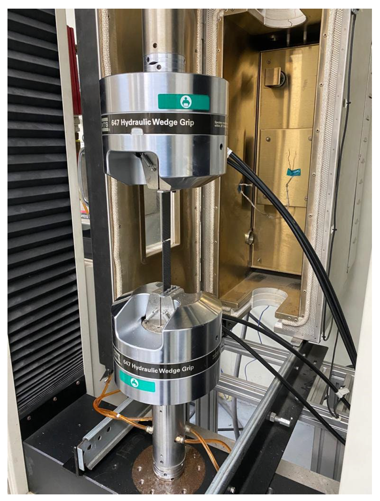
All tests were performed using an Instron 5982 universal testing machine (Instron, Norwood, MA, USA) equipped with a 100 kN load cell. To prevent specimen slippage during testing, pneumatic wedge grips were used to secure the specimens. The crosshead displacement rate was set to 2 mm/min, in accordance with the standard. To obtain accurate stress–strain measurements, an Epsilon 3542 extensometer (Epsilon Technology Corporation, Jackson, WY, USA) was attached to each specimen. Each tensile test was repeated five times to ensure statistical significance and reproducibility. The damage patterns of the specimens were analyzed using high-resolution optical microscopy (Olympus DSX510, Mitutoyo, Kanagawa, Japan) to identify fiber breakage, matrix cracking, and delamination patterns. Figure 2 shows the testing procedure for specimens.

2.2.2. Low-Energy Impact Testing

To simulate impact damage caused by hail or bird strikes, low-energy impact tests were performed using a drop-weight impact tower. The specimens were rigidly clamped along their edges to prevent excessive flexural movement during impact. A hemispherical impactor with a 16 mm diameter was used, with impact energies of 37 J and 40 J.
The impactor mass was set at 4 kg, and the drop height was adjusted to achieve the required energy levels. In the drop-weight impact setup used, the impact energy was determined based on the principle of gravitational potential energy, where the energy (E) is the product of the mass of the impactor (m), the gravitational acceleration (g), and the release height (h). This approach enables precise control of the impact energy by varying the height from which the mass is dropped, ensuring that the specified low-energy impact conditions are consistently achieved across all tests. Each impact test was conducted once per specimen, and post-impact damage characterization was performed immediately after testing. The affected areas were visually inspected for matrix cracking, fiber breakage, and delamination. Table 1 contains the dimensions of each of the specimens used for the hail impact at 37 J, while Table 2 contains the dimensions referring to the specimens used for the drone impact at 40 J.

2.3. Damage Characterization and Analysis

Composite laminates often sustain internal damage with little or no visible external signs, a phenomenon known as barely visible impact damage (BVID) [32]. This type of damage, which can include delamination, fiber-matrix debonding, and matrix cracking, significantly reduces the structural load-carrying capacity of the material. The use of non-destructive inspection (NDI) techniques, such as fluorescent dye penetrant testing and ultrasonic C-scan imaging, helped to detect subsurface delamination, microcracks, and fiber breakage that may not be evident through visual inspection alone. High-resolution microscopy analysis was used for a detailed investigation of crack initiation sites, fiber pull-out, and damage patterns, enabling a deeper understanding of how impact energy is absorbed and dissipated within the composite structure.

2.3.1. Non-Destructive Inspection

The specimens were first cleaned with acetone to remove any surface contaminants. A fluorescent penetrant (Zyglo ZL-60C, Magnaflux, Wiltshire, UK) was applied to the specimen surfaces and allowed to seep into microcracks for 15 min. Excess penetrant was removed using lint-free wipes, after which a developer (Zyglo ZP-9F) was applied to enhance the visibility of cracks. Observations were conducted under ultraviolet light, allowing for the identification of impact-induced damage. Additionally, ultrasonic C-scan imaging was performed using an Olympus Omniscan MX2 system equipped with a 10 MHz transducer to detect internal delamination and subsurface defects. The ultrasonic data were analyzed to quantify delamination area and depth, providing insight into the failure mechanisms of the impacted specimens.

2.3.2. Microscopy Analysis

High-resolution microscopy analysis was conducted using a Keyence VHX-7000 digital microscope (Keyence, Itasca, IL, USA) with a magnification range of 50× to 2000×. This analysis allowed for the detailed examination of crack initiation sites, fiber-matrix debonding, and delamination characteristics. Special attention was given to identifying the different types of damage mechanisms observed, including matrix cracking, interlaminar delamination, fiber breakage, and localized tearing within the matrix.

3. Manufacturing and Specimen Preparation

This section presents the findings obtained from the manufacturing process, mechanical testing, and damage characterization of CFRP airfoil profiles. The results are analyzed to provide insights into the structural performance, impact resistance, and failure mechanisms of the tested specimens.

Fabrication of Flat and Curved Specimens

The flat CFRP laminates were fabricated using a vacuum-assisted hand lay-up process. Surface preparation included manual cleaning of the flat aluminum molds with isopropyl alcohol and application of five successive layers of Frekote 700NC release agent. Plain weave carbon fiber fabrics were manually cut using a rotary cutter (OLFA 45 mm) on a self-healing cutting mat, following straight lines guided by a metal straightedge to minimize fraying and ensure dimensional precision. The fiber plies were arranged in a [0°, ±45°, 90°] stacking sequence, a common configuration in aerospace applications for balancing mechanical properties [33]. Each ply was impregnated manually with epoxy resin using a hard rubber roller and bristle brushes, ensuring complete fiber wetting and minimal air entrapment. Vacuum bagging was applied with a vacuum pressure of −0.85 bar and maintained during a 24 h ambient cure at 25 ± 2 °C. After curing, the cutting of flat specimens was performed using a Proxxon FET precision bench saw fitted with a fine-tooth diamond blade. Cutting was carried out in multiple light passes to prevent edge delamination, maintaining fiber continuity along the edges. Final dimensional verification was performed using a Mitutoyo digital caliper with ±0.01 mm precision. Specimens showing visual surface defects after cutting were discarded.
The SC(2)-0714 and GOE777-IL airfoil profiles were manufactured separately using a vacuum-assisted hand lay-up method over 3D curved molds. The mold surfaces were cleaned with isopropyl alcohol and treated with Frekote 700NC release agent. Carbon fiber fabrics were pre-cut manually using a rotary cutter, following full-scale airfoil templates designed to match the chord length and thickness distribution. Lay-up followed the same stacking sequence as flat CFRP laminates. Each ply was impregnated with epoxy resin using a roller and brush technique to ensure complete wetting, especially along curved sections. The laminates were vacuum bagged and cured at room temperature for 24 h under a vacuum of −0.85 bar. After curing, the cutting and preparation of airfoil profiles involved a two-step manual process:
  • Gross trimming was performed using a Dremel 3000 rotary tool (Dremel, Mount Prospect, IL, USA) fitted with a thin abrasive cutting disk to remove flash and excess resin around the perimeter.
  • Precision sectioning along the chord and span was performed using the Dremel rotary tool guided by manually delineated cutting lines based on CAD templates.
Curved trailing edge zones were hand-finished with diamond abrasive files to preserve aerodynamic smoothness and avoid fiber pull-out. Dimensional checks were performed with a Mitutoyo caliper to ensure consistent chord length and thickness across sections. Specimens exhibiting surface defects, as identified through non-destructive visual inspection, were discarded to maintain consistency in mechanical testing.
Tensile specimens were cut according to the ASTM D3039 [34], with final dimensions of 250 mm × 25 mm × 3.2 mm, while impact specimens were prepared according to ASTM D7136 [35], measuring 150 mm × 100 mm × 3.2 mm. The measured final laminate thickness was 3.2 mm ± 0.1 mm, indicating consistency across all specimens.

4. Results

4.1. Tensile and Impact Results

4.1.1. Tensile Testing Results

Tensile tests were performed on both non-impacted and impacted CFRP specimens to evaluate their ultimate tensile strength (UTS) and elastic modulus. The results are summarized in Table 3, where the mean values and standard deviations are reported.
The non-impacted specimens exhibited an average tensile strength of 920.4 MPa, demonstrating the high load-bearing capability of the CFRP laminates. However, specimens subjected to low-energy impacts (37 J and 40 J) showed a reduction of approximately 19% and 25%, respectively, in their UTS values. This decrease confirms that impact-induced damage significantly affects the residual strength of composite structures, even when no visible surface damage is present.
Failure analysis revealed that non-impacted specimens predominantly failed due to fiber rupture at ultimate load, whereas impacted specimens exhibited delamination-driven failures, leading to premature fracture. These findings indicate that low-energy impacts compromise the structural integrity of CFRP airfoils, necessitating further damage tolerance assessments.

4.1.2. Impact Testing Results

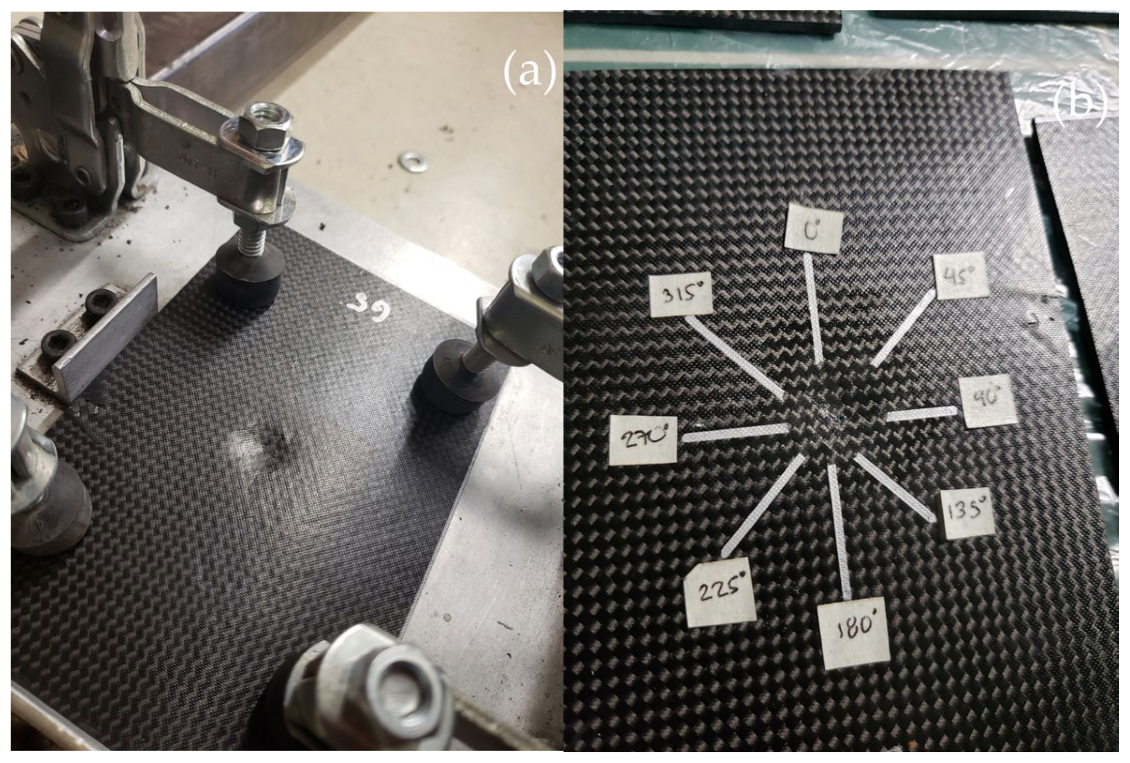
The impact tests were conducted on twelve CFRP laminates, with six subjected to an impact energy of 37 J and six to 40 J, using a drop-weight impact tower with a hemispherical impactor. The drop height was set to 0.942 m for 37 J and 1.02 m for 40 J, with a 4 kg impactor mass. To assess impact damage along the X, Y, and Z axes, a vernier caliper was used to ensure precise dimensional quantification. For each laminate, the damage dimensions were measured at specific angles (0°, 45°, 90°, 135°, 180°, 225°, 270°, and 315°) to assess the damage propagation directionality. These angles were selected based on standard recommendations to analyze failure trends in composite laminates. Figure 3 shows the testing results and damage quantification for each specimen.
The results demonstrated that higher impact energy increased the damage area and severity, with delamination and matrix cracking becoming more prominent at 40 J. At 37 J, denting was the dominant damage pattern, while 40 J impacts resulted in higher occurrences of fiber breakage and interlaminar delamination. The damage distribution analysis revealed that crack propagation followed a fiber orientation-dependent pattern, with maximum damage occurring at 45° and minimal damage at 225°, aligning with the stacking sequence of the laminates. The results are summarized in Table 4.
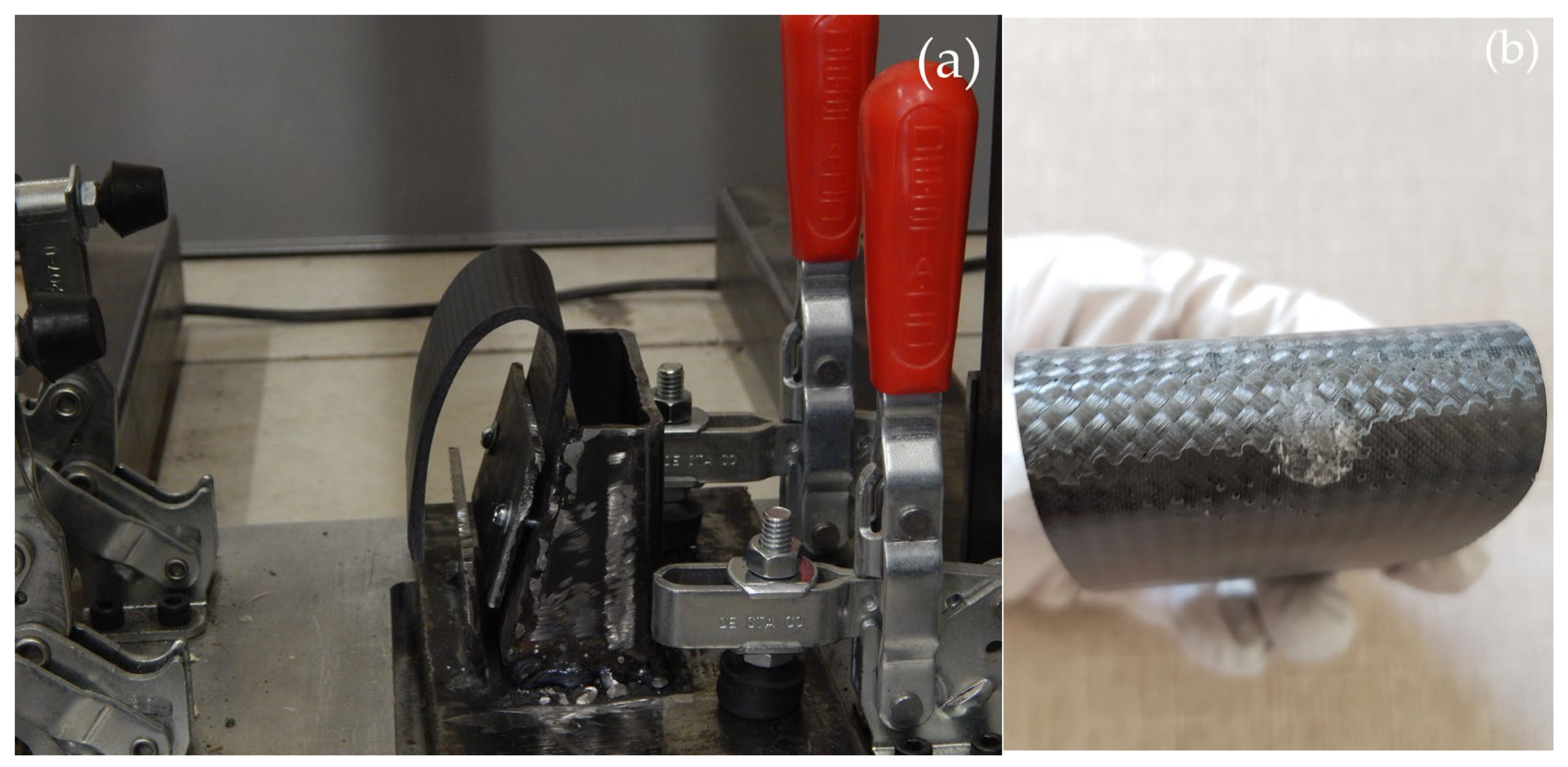
The GOE777-IL and SC(2)-0714 airfoil profiles were subjected to impact tests with an energy of 40 J, evaluating damage patterns and the resulting surface damage. Figure 4 shows the setup for the impact tests.
The results indicate that in the GOE777-IL profiles, the posterior damage exhibits an oval geometry, while the frontal damage is circular due to the shape of the spherical indenter. In some cases, the damage in the posterior section was more severe, posing a risk in structural applications, as it could go unnoticed during visual inspections. For the SC(2)-0714 profiles, the dimensional analysis of the damage shows a high similarity between the dimensions of the frontal and posterior damage. Table 5 presents the average values of maximum force, absorbed energy, and damage area obtained for both profiles.
The GOE777-IL profile exhibited a 9.4% higher maximum force and 4.6% greater absorbed energy compared to the SC(2)-0714, suggesting greater impact resistance and stiffness. However, the SC(2)-0714 profile presented a 40% larger damage area, indicating higher susceptibility to impact-induced damage. Both profiles exhibited fracture/crack and delamination as predominant damage patterns, with the SC(2)-0714 profile showing a higher potential for crack propagation, while the GOE777-IL profile demonstrated superior impact resistance with a lower damage area. Additional non-destructive testing (NDT) methods were used to assess internal damage propagation.
To statistically validate the influence of impact energy on the residual tensile performance of the specimens, a one-way analysis of variance (ANOVA) was performed using the ultimate tensile strength (UTS) values obtained from the three groups: non-impacted, impacted at 37 J, and impacted at 40 J. The ANOVA revealed a statistically significant difference between the groups, with an F-value of 772.13 and a corresponding p-value of less than 0.001. This result confirms that the observed reductions in UTS (19–25%) are not due to random variability but rather reflect a consistent and measurable effect of the impact condition on the post-impact mechanical behavior of the composites.

4.2. Damage Analysis

4.2.1. NDT Results

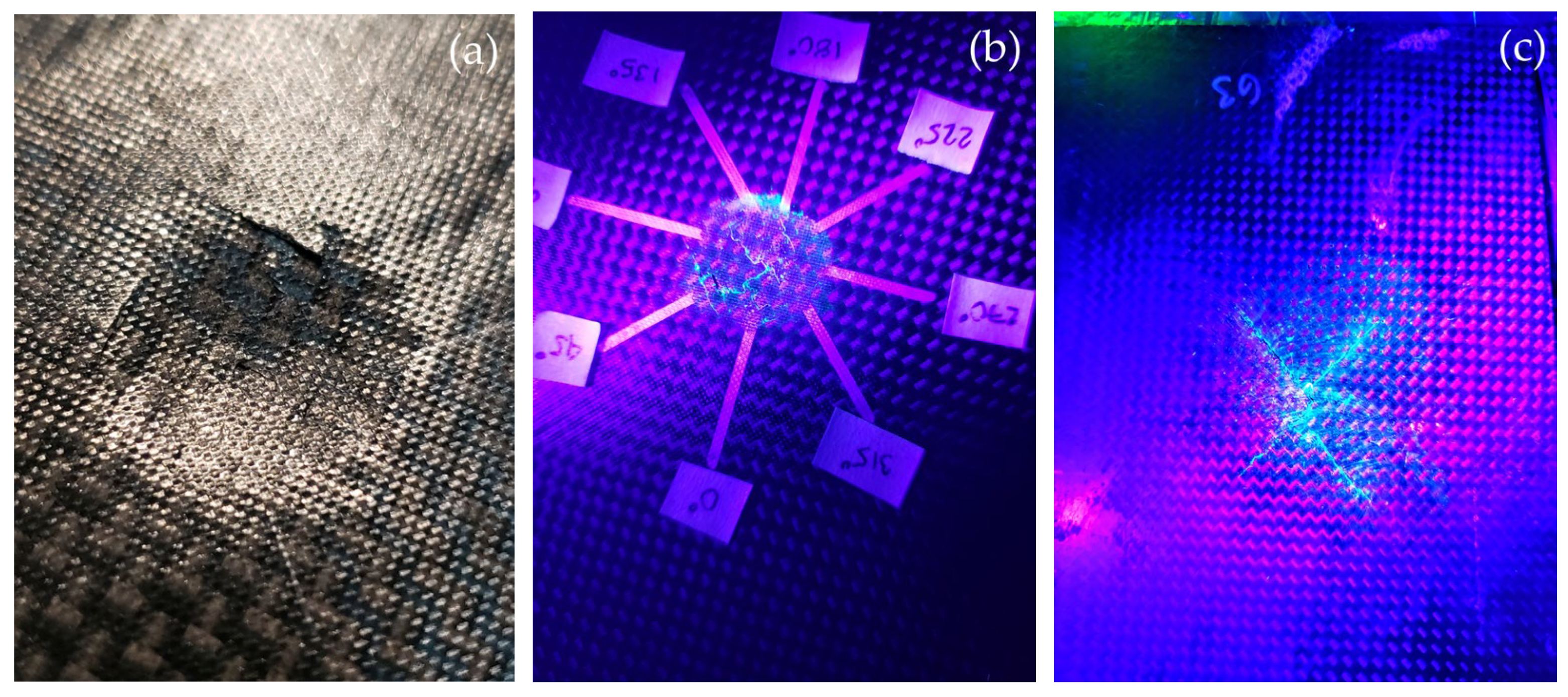
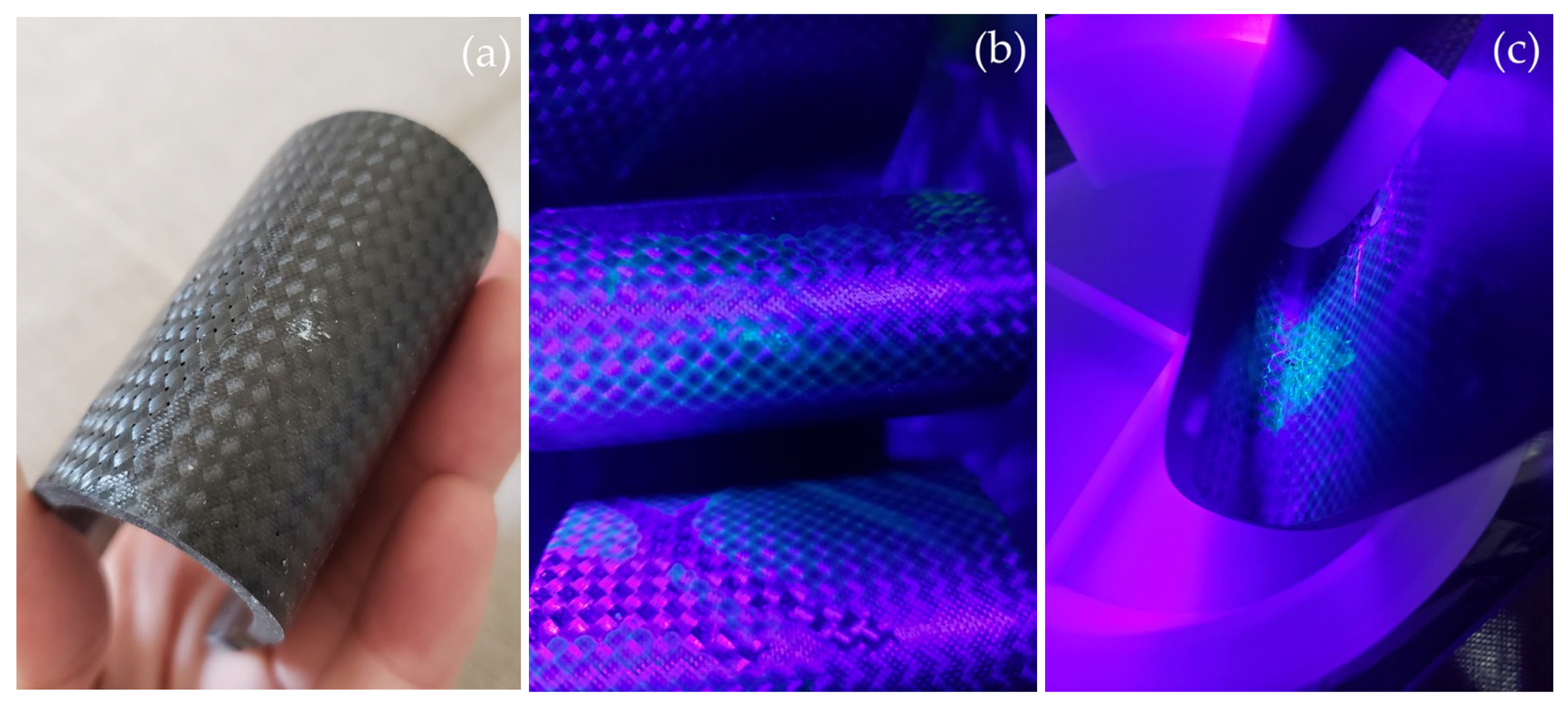
Post-impact damage evaluation was carried out using fluorescent dye penetrant testing following the ASTM E1417 standard [36]. The damage assessment process began with visual inspection, which allowed for the initial identification of surface defects such as indentation, fiber breakage, and visible matrix cracking. To enhance damage detection, fluorescent dye penetrant testing was performed. The liquid penetrant was applied using a dropper, ensuring precise coverage over the impacted regions. After a waiting period of a few minutes, the excess dye was removed, and the specimens were illuminated under UV light to reveal cracks and delaminations that were otherwise invisible. Figure 5 shows the NDT analysis on CFRP laminates.
The first image depicts an impacted specimen secured in a fixture displaying a visible dent or deformation at the center due to a controlled impact event with minimal surface damage, indicating that most of the energy was absorbed internally. The second image, taken under UV light, reveals that the fluorescent dye penetrant has seeped into cracks and defects, highlighting radial crack propagation extending outward from the impact site, with small markers indicating measurement points for crack length and width assessment. The third image further exposes a more extensive damage region on the back of the CFRP laminate, revealing subsurface delamination and fiber-matrix debonding, where the X-shaped damage pattern suggests interlaminar cracking due to shear stresses induced by the impact, and the fluorescent response confirms that the extent of the damage is greater than what is visually detectable under normal lighting.
CFRP airfoils reveal the extent of low-energy impact damage that may not be visible under normal lighting conditions. The initial observation of the impacted airfoil suggests minimal surface damage, indicating that the impact energy was largely absorbed internally. However, under UV light exposure, the fluorescent dye highlights radial crack propagation and fiber-matrix debonding, confirming the presence of interlaminar defects. The backside inspection further exposes subsurface delamination, where a more extensive damage zone is evident, emphasizing the redistribution of impact-induced stress within the composite structure. Figure 6 shows the NDT analysis on CFRP airfoils.

4.2.2. Microscopy Analysis and Damage Patterns

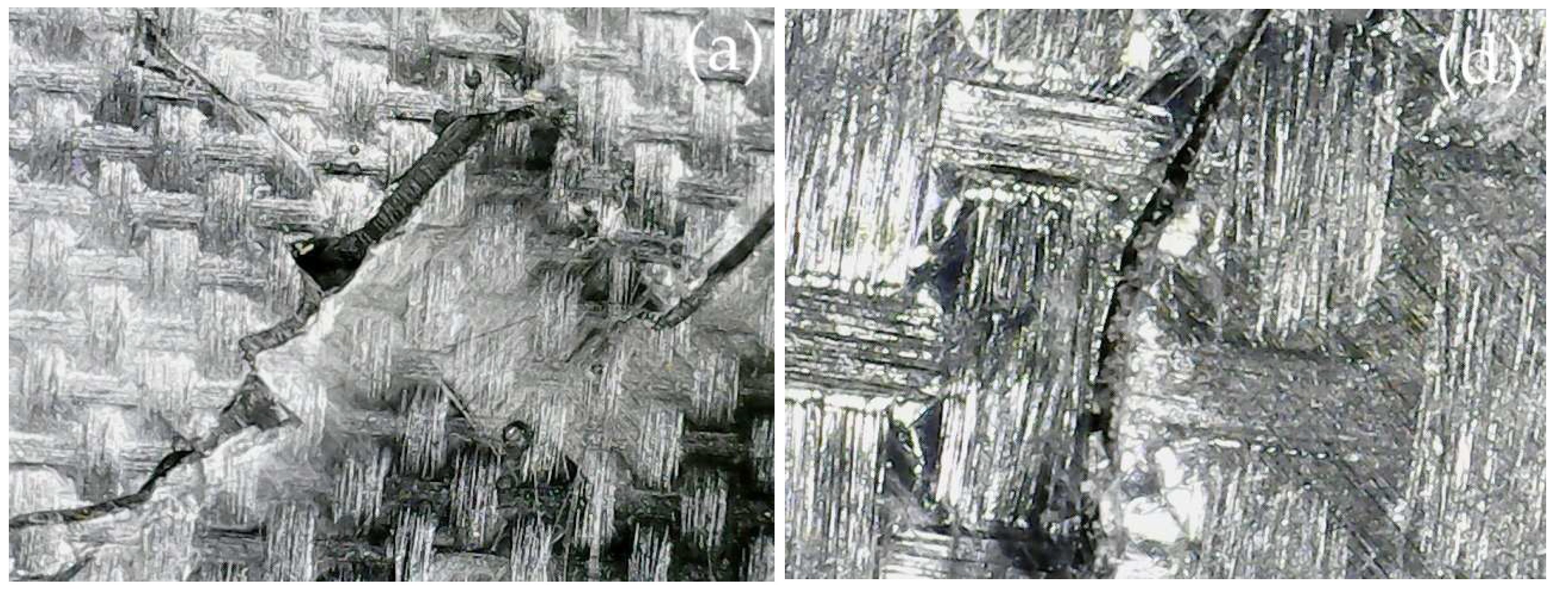
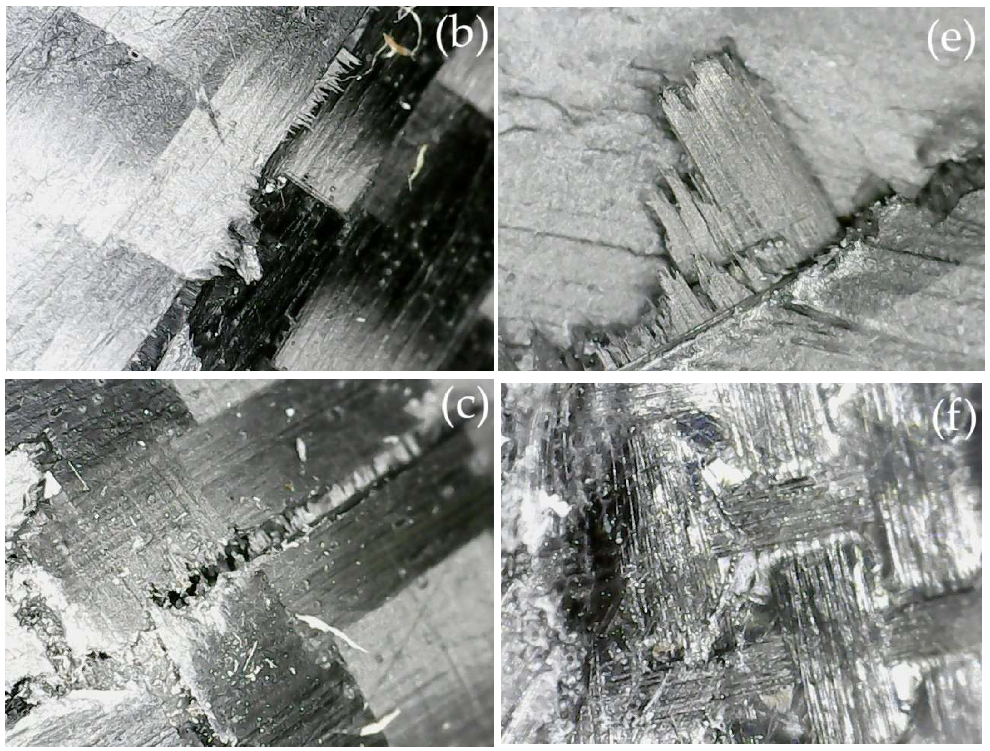
High-resolution microscopy was used to investigate failure mechanisms at the microstructural level. The analysis revealed that impact damage in CFRP laminates and airfoils followed a progressive failure sequence, transitioning through multiple damage patterns as energy was absorbed by the composite material. Three primary damage patterns were identified, and Figure 7 and Figure 8 show the frequency of each damage pattern in the different samples for the impact tests.
  • Matrix Cracking (MC): These cracks appeared in regions subjected to high tensile stresses, primarily near the impact site. Crack propagation was observed perpendicular to fiber orientation, indicating matrix-dominated failure in tensile-loaded areas.
  • Interlaminar Delamination (ID): Delaminations were concentrated along the mid-thickness plane, particularly in areas where interlaminar shear stresses were highest. The separation of fiber layers confirmed interlaminar failure, a common damage mechanism in laminated composite structures.
  • Debonding and Matrix Tearing (DMT): Microscopy analysis revealed fiber-matrix debonding and matrix cracking, particularly in off-axis plies laminates. These cracks were more pronounced in specimens subjected to higher impact energy (40 J), demonstrating that increased impact loads exacerbate fiber-matrix separation.
The microscopic analysis of CFRP laminates and airfoils is shown in Figure 9. Figure 9a demonstrates a clear separation between the carbon fibers and the surrounding epoxy matrix, indicative of fiber-matrix debonding. This type of damage is associated with shear stresses that exceed the bonding strength at the fiber-matrix interface, leading to delamination. Figure 9b shows severe fiber breakage, where the carbon fibers have fractured completely due to high-energy impact. The jagged crack path suggests that the material has reached its ultimate tensile strength, causing a brittle fracture. Figure 9c reveals cracks propagating through the epoxy matrix, often appearing before more severe failures like fiber-matrix debonding or fiber breakage.
Figure 9d illustrates the microscopic analysis of CFRP airfoils, revealing a progression of failure mechanisms. The visible crack running through the resin matrix suggests matrix cracking failure, where the polymer phase fractures under tensile stresses perpendicular to the crack plane, while the fibers remain mostly intact, indicating that the failure originated in the matrix before propagating into the fiber-reinforced structure. Figure 9e shows clear fiber-matrix debonding, characteristic of interlaminar delamination, where fibers appear detached from the resin matrix, suggesting that shear stresses exceeded the interfacial adhesion strength between the two phases. Figure 9f presents a post-impact inspection of CFRP airfoils, where no apparent damage is observed in the initial visual assessment. However, under microscopic magnification, damage patterns can be identified in CFRP laminates, demonstrating that damage may not always be visible during standard inspections. Notably, debonding and matrix tearing were not observed in any of the tested airfoil samples, indicating that the structural integrity of the fibers was preserved despite the presence of matrix and interfacial failures. In GOE777-IL airfoils, delamination extended along the fiber orientation and propagated outward from the impact zone, whereas in SC(2)-0714 airfoils, damage remained more localized. These findings suggest that airfoil geometry plays a key role in damage distribution and resistance to impact, highlighting the necessity of proper damage detection and repair protocols in composite airfoils.
The reduction in tensile strength observed after low-energy impacts is attributed to a combination of micromechanical damage mechanisms that were confirmed through post-impact microscopy. Interfacial debonding plays a central role, as loss of adhesion between fiber and matrix generates stress concentrations that facilitate crack nucleation under subsequent tensile loading. These interfacial failures are visible as fiber pull-out regions and void-like separations along the interface, particularly in specimens impacted at 37 J and 40 J. Matrix plasticity also contributes to strength degradation by absorbing part of the impact energy through localized deformation, but this plastic flow leads to resin microcracking and loss of load transfer continuity. Micrographs revealed opening cracks propagating perpendicularly to the fibers, initiated within resin-rich pockets. Simultaneously, interlaminar delamination was observed between plies, especially in areas with higher curvature or ply drop-off, consistent with interlaminar stress concentration. In the 40 J case, fiber breakage and fiber kinking were also evident, indicating that the energy threshold for fiber-dominated failure had been exceeded. These combined damage patterns reduce the structural integrity of the laminate, altering the post-impact stress distribution and explaining the observed 19–25% decrease in tensile strength.

5. Discussion

The results of the impact tests indicate that damage distribution in CFRP laminates is strongly influenced by fiber orientation, with a notable concentration of damage occurring at 45°. At this angle, delamination and fiber-matrix debonding were the most pronounced, which aligns with the expected behavior of composite materials under shear-dominated loading conditions. Fiber orientation plays a crucial role in crack propagation, as energy dissipation within the laminate follows the preferential failure paths dictated by the stacking sequence. Conversely, the least amount of damage was observed at 225°, suggesting that certain fiber orientations provide higher resistance to impact-induced stress, likely due to the load redistribution effect along the primary load-bearing directions.
The increase in impact energy from 37 J to 40 J resulted in larger damage areas, confirming that higher impact energy leads to more severe delamination growth. This trend is consistent with prior studies on composite impact resistance [5,6,9,13], where exceeding a threshold impact energy results in progressive interlaminar failure. The observed damage distribution suggests that crack propagation in CFRP laminates is energy-dependent, with higher energies promoting interlaminar separation and fiber breakage.
Microscopy analysis further revealed that damage initiation occurs primarily at 45°, with cracks propagating along interlaminar regions. The presence of fiber bridging and crack deflection in certain orientations suggests that some fiber alignments contribute to improved energy dissipation, reducing catastrophic failure propagation. The anisotropic failure characteristics of CFRP laminates observed in this study reinforce the need for optimized stacking sequences to enhance impact resistance.
Regarding the airfoil specimens, the results confirmed that curved geometries tend to distribute impact loads more effectively, reducing visible surface damage while increasing internal delamination risk. This is particularly significant for structural applications, where non-visible impact damage (BVID) can compromise structural integrity over time [37].
The variability associated with the hand lay-up process in mechanical properties can be mitigated by improving manufacturing repeatability. Automated Fiber Placement (AFP) has emerged as a promising alternative [38]. The integration of machine learning into AFP-based inspection systems enables real-time defect identification, reducing human subjectivity and enhancing laminate quality consistency across batches. Moreover, combining AFP with additive manufacturing allows for highly customized fiber orientations on complex geometries, significantly minimizing common lay-up defects such as wrinkling and fiber misalignment [39]. Complementary work provides experimental evidence showing that AFP reduces wrinkle variability when fiber steering is optimized, especially in substrates with controlled curvature. Other contributions introduce a novel tape termination method that suppresses delamination in ply drop-off zones, thereby maintaining structural integrity and uniform stress distribution [40,41]. Lastly, robotic AFP-AM hybrid systems demonstrate high repeatability and dimensional control, showing that compaction force and heating parameters can be finely tuned to reduce porosity and ensure proper fiber alignment [42]. These findings collectively support the adoption of AFP as a viable approach to enhance the reliability and performance of composite structures fabricated for structural applications.
While µCT analysis was not conducted in the present study, void content was controlled through vacuum-assisted processing and specimen selection based on visual inspection. However, existing studies indicate that even void levels under 2.5% can significantly influence matrix-dominated properties. It has been reported that void contents as low as 2% can reduce interlaminar shear strength (ILSS) by up to 10%, especially when voids concentrate along interlaminar regions where crack initiation is more probable [43]. Additionally, the morphology and distribution of voids—whether interfiber or matrix-type—modulate local stress fields, affecting the onset and evolution of delamination and energy dissipation during impact events [44]. This behavior is particularly critical in curved composite structures, such as the airfoils studied, where internal stresses may concentrate at fiber-matrix interfaces and resin-rich zones. Although no µCT of void content characterization was performed in this work, future studies could incorporate advanced imaging and micromechanical modeling to better understand the spatial correlation between void distribution and failure mechanisms under low-velocity impact. Insights from recent high-pressure curing and digital material simulations also suggest that threshold porosity levels, void shape, and fiber-to-void ratios are key parameters in determining the mechanical reliability of CFRP structures [44,45].
Although tensile tests in this study were performed under quasi-static conditions (2 mm/min), it is well established that epoxy matrices exhibit significant strain-rate sensitivity. Recent studies employing Split Hopkinson Pressure Bar (SHPB) testing on carbon fiber-reinforced epoxy composites have shown that, under dynamic tensile loading (strain rates ranging from approximately 1200 to 2400 s−1), the failure mechanisms shift noticeably. Matrix cracking becomes more dominant, often accompanied by localized adiabatic shear band formation and interfacial delamination between fibers and matrix [46,47]. Notably, the dynamic tensile strength of epoxy-based composites has been reported to increase by up to 28% in comparison to quasi-static tests, while the strain-to-failure remains relatively constant [48]. This indicates an enhanced energy absorption capability under rapid loading, but also a tendency toward more brittle fracture behavior that may compromise the residual strength of impacted laminates. These observations highlight the importance of incorporating high-strain-rate testing in future campaigns, particularly for structural components exposed to impact or crash conditions [47,48,49].
The comparison between flat and curved CFRP specimens revealed significant differences in their response to low-velocity impact. Flat laminates exhibited a more uniform stress distribution across the impact surface, which resulted in damage patterns primarily governed by fiber orientation and matrix damage. In contrast, curved specimens such as the SC(2)-0714 and GOE777-IL airfoils experienced more complex failure mechanisms due to geometric effects. The curvature introduced radial and axial stress gradients, which altered the propagation of transverse and longitudinal strain waves. This led to localized strain energy concentrations and asymmetric damage propagation, particularly at ply interfaces where interlaminar shear is intensified. Finite element simulations from related studies have demonstrated that curved panels can exhibit higher peak contact forces, greater total energy absorption, and increased back face displacement when compared to flat ones, due to dynamic stiffening and out-of-plane deformation effects [50,51]. In the present work, experimental results confirm that curvature not only modifies the extent and morphology of damage (wider delamination fronts, eccentric crack patterns), but also influences the residual tensile strength, which was more severely affected in highly curved sections of the GOE777-IL profile. These observations support the hypothesis that curvature plays a decisive role in impact resistance by altering the internal stress fields and failure evolution. Therefore, accounting for geometric effects is crucial when designing composite structures with curved profiles, as conventional damage tolerance criteria developed for flat specimens may underestimate internal degradation in complex geometries. Curvature intensifies stress gradients and shear responses, particularly at ply interfaces, which contribute to distinct damage morphologies [52]. In the context of the present study, the contrasting curvatures of the SC(2)-0714 and GOE777-IL airfoils generate measurable differences in absorbed impact energy, damaged area, and residual tensile strength, confirming the critical role of geometry in defining structural response under low-velocity impact conditions [50,51,52].
It is important to note that no axial preloading was applied to the specimens during impact testing. This includes the curved airfoil specimens, which were mounted without axial constraints to isolate the role of geometric curvature on the impact response. While this setup aligns with standard testing procedures, previous studies suggest that axial pre-tension may reduce impact-induced damage by increasing in-plane stiffness, whereas axial compression could lead to premature local buckling and amplify delamination through increased interlaminar shear. Experimental findings have shown that applying axial tension to composite laminates can limit matrix cracking and delay the progression of interlaminar failure under impact loading [37]. Other studies have indicated that the combination of curvature and axial constraints generates complex stress fields that significantly influence damage initiation and propagation patterns [53]. Additionally, it has been observed that curved panels under axial compression exhibit earlier buckling onset and increased delamination areas compared to those tested under tension or without constraints [54].
These findings emphasize the need for comprehensive damage detection strategies, as conventional visual inspection may underestimate internal damage. Future studies should explore advanced non-destructive evaluation techniques and numerical modeling approaches to refine damage tolerance predictions in aerospace composites and the coupled effects of curvature and axial loading on the damage tolerance of composite structures under realistic in-service conditions.

6. Conclusions

The impact tests demonstrated that damage distribution varies significantly depending on fiber orientation, with localized back-surface damage observed in both 37 J and 40 J impact scenarios. The presence of severe delamination and matrix cracking at 45° suggests that shear stresses dominate failure behavior in composite laminates. Conversely, damage was minimal at 225°, indicating that specific fiber orientations contribute to increased impact resistance. The effect of impact energy was evident, as higher energy levels resulted in larger damage areas and more pronounced interlaminar separation. These results align with the standards, which classify denting and matrix cracking as dominant damage patterns in low-velocity impact events. The statistical significance of the strength reduction, confirmed by ANOVA, reinforces the influence of energy absorption and localized damage mechanisms on the residual load-carrying capacity. This result supports physical observations and suggests that even low-energy impacts produce consistent and quantifiable structural degradation.
The current experimental results demonstrated that post-impact damage, including matrix cracking, fiber-matrix interfacial debonding, and delamination, led to a reduction in residual tensile strength in the SC(2)-0714 and GOE777-IL airfoil specimens. In flight, these profiles would be exposed to complex aerodynamic loadings involving both tensile and compressive stresses distributed asymmetrically across their surfaces. Tensile forces acting on the upper (suction) side of the airfoils would exacerbate pre-existing delaminations and matrix cracks, promoting further crack propagation and localized fiber bridging failure. Conversely, compressive stresses predominant on the lower (pressure) side could trigger fiber micro-buckling, interfacial shear degradation, and accelerated delamination growth, particularly around previously impacted zones where interlaminar integrity is already compromised. Given the different curvature and thickness distributions between SC(2)-0714 and GOE777-IL, the stress fields and damage evolution under flight loads would not be uniform; profiles exhibiting higher curvature would experience amplified transverse stresses and more severe damage progression under compression. These findings underline the necessity of integrating post-impact residual strength assessments with compression-after-impact testing protocols and suggest that future evaluations should incorporate combined loading paths to more accurately replicate operational conditions in composite airfoil structures.
For airfoil specimens, the findings confirmed that curved geometries distribute impact loads more effectively, resulting in less visible surface damage but increased internal delamination risks. The presence of small cracks caused by microscopic air bubbles during the manual vacuum-curing process suggests that manufacturing variables influence composite damage resistance. Fluorescent dye penetrant testing provided a more accurate assessment of crack propagation, confirming interlaminar damage beyond what was visible through standard inspection methods. These findings highlight the importance of advanced non-destructive inspection (NDI) techniques, particularly in structural applications, where early detection of interlaminar damage is crucial for maintaining structural integrity.
Environmental aging factors such as moisture absorption, thermal cycling, and UV exposure can critically affect the interfacial adhesion and post-impact behavior of epoxy-based composites. Although accelerated aging tests were not conducted in this study, existing literature indicates that moisture ingress can plasticize the epoxy matrix, reduce stiffness, and degrade fiber–matrix interfacial bonding, especially at elevated temperatures where thermal expansion accelerates water diffusion and interfacial debonding [55]. Prolonged hygrothermal exposure is also associated with crack initiation and delamination, as a mismatch in volumetric expansion induces internal stresses and matrix swelling. UV radiation further compounds these effects, leading to surface embrittlement, microcracking, and loss of structural integrity. Therefore, future studies should evaluate the combined impact of environmental factors on residual mechanical performance, including interfacial strength and energy absorption, to fully characterize long-term durability [56].

Author Contributions

Conceptualization, I.J.B. and V.G.A.; methodology, I.J.B. and V.G.A.; investigation: I.J.B.; writing—original draft, I.J.B., V.G.A. and M.S.H.; writing—review and editing, I.J.B., V.G.A., M.S.H., E.S.D.R., H.D.M.-A., L.E.V.O. and B.G.V. All authors have read and agreed to the published version of the manuscript.

Funding

This research received no external funding.

Data Availability Statement

Data is contained within the article.

Conflicts of Interest

The authors declare no conflict of interest.

References

  1. He, D.; Kim, H.C.; Sommacal, S.; Stojcevski, F.; Soo, V.K.; Lipiński, W.; Morozov, E.; Henderson, L.C.; Compston, P.; Doolan, M. Improving mechanical and life cycle environmental performances of recycled CFRP automotive component by fibre architecture preservation. Compos. Part A Appl. Sci. Manuf. 2023, 175, 107749. [Google Scholar] [CrossRef]
  2. Guo, R.; Li, C.; Niu, Y.; Xian, G. The fatigue performances of carbon fiber reinforced polymer composites—A review. J. Mater. Res. Technol. 2022, 21, 4773–4789. [Google Scholar] [CrossRef]
  3. Frhaan, W.K.M.; Abu Bakar, B.H.; Hilal, N.; Al-Hadithi, A.I. CFRP for strengthening and repairing reinforced concrete: A review. Innov. Infrastruct. Solut. 2021, 6, 49. [Google Scholar] [CrossRef]
  4. Zhang, H.; Yang, L.; Ren, S.; Wang, K.; Li, J. In-situ experimental characterization and numerical investigation of the crack initiation of SMC composite under uniaxial tension. Compos. Part A Appl. Sci. Manuf. 2025, 188, 108543. [Google Scholar] [CrossRef]
  5. Liu, Z.; Li, P. Effect of fiber orientation of adjacent plies on the mode I delamination fracture of carbon fiber reinforced polymer multidirectional laminates. Polym. Compos. 2025, 46, 2560–2572. [Google Scholar] [CrossRef]
  6. Duan, L.; Zhang, Y.; Yan, L.; Bao, S.; Liu, H.; Lu, J. Investigation on the crack development behaviour of CFRP strengthened RC beams under static and impact loading. Eng. Fail. Anal. 2025, 171, 109369. [Google Scholar] [CrossRef]
  7. Liu, Q.; Liu, Y.; Yu, C.; Chen, H.; Chen, Y.; Liu, Y. Mechanical property and fracture characteristics of carbon fiber reinforced aluminum matrix composites prepared by friction stir welding. J. Mater. Res. Technol. 2025, 34, 1080–1089. [Google Scholar] [CrossRef]
  8. Jiang, L.; He, X.; Zhao, Y.; Li, P.; Zhao, Y.; Wang, Z.; Guo, D.; Gu, Q. Experimental study on the strengthening mechanism of carbon fiber-reinforced sand powder 3D-printed rock-like materials. Case Stud. Constr. Mater. 2025, 22, e04275. [Google Scholar] [CrossRef]
  9. Li, C.X.; Kalfon-Cohen, E.; Lee, J.; Furtado, C.; Patel, P.; Kopp, R.; Hank, T.J.; Magato, J.; Kinsella, M.; Kessler, S.S.; et al. Interlaminar reinforcement of carbon fiber reinforced polyimide composites using vertically aligned carbon nanotubes. Compos. Part B Eng. 2024, 292, 112098. [Google Scholar] [CrossRef]
  10. Hou, N.; Guo, Q.; Zaïri, F.; Ding, N. Mode I crack propagation in polydimethylsiloxane-short carbon fiber composites. Compos. Struct. 2025, 352, 118682. [Google Scholar] [CrossRef]
  11. Sanchez, J.F.R.; Waas, A.M. Experimental results for fatigue damage growth in laminated fiber reinforced cross-ply laminates. Compos. Struct. 2025, 352, 118702. [Google Scholar] [CrossRef]
  12. Aşkan, A.; Aydın, M. The role of impact energy and silica concentration on dynamic impact and quasi-static puncture resistance of fabrics treated with shear-thickening fluids. Compos. Struct. 2025, 352, 118689. [Google Scholar] [CrossRef]
  13. Balaga, U.K.; Gargitter, V.; Yarlagadda, S.; Heider, D.; Crane, R.; Tierney, J.; Advani, S.G. Influence of ply thickness on transverse cracking onset, damage progression in thin ply composites and impact on mechanical performance. Compos. Struct. 2025, 354, 118827. [Google Scholar] [CrossRef]
  14. Feki, I.; Shirinbayan, M.; Nouira, S.; Bi, R.T.; Maeso, J.-B.; Thomas, C.; Fitoussi, J. Multi-scale fatigue damage analysis in filament-wound carbon fiber reinforced epoxy composites for hydrogen storage tanks. Compos. Part C Open Access 2024, 15, 100537. [Google Scholar] [CrossRef]
  15. Raza, H.; Rodera, O.; Carpenter, K.; Pärnänen, T.; Jokinen, J.; Kanerva, M.; Bayandor, J. Predictive methods for initiation of delamination and intra-laminar damage in carbon fibre reinforced polymer laminates subject to impact. Aeronaut. J. 2024, 128, 846–874. [Google Scholar] [CrossRef]
  16. Yan, K.; Cao, X.; Xie, X.; Mei, H.; Tang, J.; Sun, X.; Ren, F. Loading rate effect on the shear behavior of the carbon fiber/epoxy interface. Compos. Sci. Technol. 2024, 257, 110785. [Google Scholar] [CrossRef]
  17. Zhang, Y.; Gui, Z.; Ma, S.; Nan, B.; Xiong, S. Tensile impact behaviors and damage mechanism of woven carbon fiber-reinforced-polymer laminates considering adiabatic shear band. Eng. Fail. Anal. 2024, 158, 107995. [Google Scholar] [CrossRef]
  18. Dong, T.; Zhao, Z.; Zheng, B.; Chen, C.; Ma, P. Response and damage mechanism of carbon/aramid intra-ply hybrid weft-knitted reinforced composites under low-velocity impact. Thin-Walled Struct. 2023, 196, 111495. [Google Scholar] [CrossRef]
  19. Abdullah, S.S.; Bokti, S.; Wong, K.; Johar, M.; Chong, W.; Dong, Y. Mode II and mode III delamination of carbon fiber/epoxy composite laminates subjected to a four-point bending mechanism. Compos. Part B Eng. 2024, 270, 111110. [Google Scholar] [CrossRef]
  20. Sulaiman, B.H.; Abdo, A.R.; Erkliğ, A.; Bozkurt, Ö.Y.; Bulut, M. Effectiveness of multi-walled carbon nanotube on the improvement of tensile, flexural, and low-velocity impact properties of hybrid Kevlar/carbon fiber reinforced epoxy-based composites. Polym. Compos. 2024, 45, 7647–7660. [Google Scholar] [CrossRef]
  21. Ayyagari, S.; Al-Haik, M. Mitigating Crack Propagation in Hybrid Composites: An Experimental and Computational Study. J. Compos. Sci. 2024, 8, 122. [Google Scholar] [CrossRef]
  22. Wang, H.; Liu, Z.; Liu, Z.; Ren, Y.; Jiang, H. Hybrid effects and failure mechanisms of carbon/Kevlar fiber composite laminates under the bending-after-impact loading. Eng. Struct. 2024, 299, 117101. [Google Scholar] [CrossRef]
  23. Ali, H.Q.; Aydin, M.S.; Khan, R.M.A.; Yildiz, M. The role of “thickness effect” on the damage progression and crack growth inside the plain-woven carbon fiber composites. Compos. Sci. Technol. 2023, 241, 110108. [Google Scholar] [CrossRef]
  24. Li, J.; Yang, L.; Xie, H.; Wei, P.; Li, D.; Xu, Y.; Zhang, F. Research on impact toughness and crack propagation of basalt fiber reinforced concrete under SHPB splitting test. J. Build. Eng. 2023, 77, 107445. [Google Scholar] [CrossRef]
  25. Deng, Y.; Tu, H.; Hu, Z. In-situ analysis of mode I delamination behaviour of carbon fibre/epoxy composites with chopped aramid/flax fiber reinforcement by X-ray micro-computed tomography. Compos. Part B Eng. 2025, 297, 112247. [Google Scholar] [CrossRef]
  26. Peng, J.; Cai, D.; Qian, Y.; Liu, C. Low-velocity impact and compression after impact behavior of 3D integrated woven spacer composites. Thin-Walled Struct. 2022, 177, 109450. [Google Scholar] [CrossRef]
  27. Shi, W.; Guo, Y.; Liu, Y.; Wang, W.; Duan, P.; Bian, H.; Chen, J. Impact of basalt fiber on the fracture properties of recycled aggregate concrete. Constr. Build. Mater. 2024, 418, 135363. [Google Scholar] [CrossRef]
  28. Lei, Z.; Ma, J.; Sun, W.; Yin, B.; Liew, K. Low-velocity impact and compression-after-impact behaviors of twill woven carbon fiber/glass fiber hybrid composite laminates with flame retardant epoxy resin. Compos. Struct. 2023, 321, 117253. [Google Scholar] [CrossRef]
  29. Reiner, J.; Fu, Y.-F. Data-driven parameter identification to simulate progressive damage in fiber reinforced laminates under low velocity impact. Int. J. Impact Eng. 2023, 180, 104711. [Google Scholar] [CrossRef]
  30. Al-Areqi, A.M.; Aloyaydi, B.; Subbarayan, S.; Al-Mufadi, F.A. Low-velocity impact performance of 3D-printed PLA/Epoxy/Glass fibers of composite structures and latches. Mater. Today Commun. 2024, 39, 109264. [Google Scholar] [CrossRef]
  31. Goraj, Z.J.; Kustron, K. Review of current research trends in bird strike and hail impact simulations on wing leading edge. Aircr. Eng. Aerosp. Technol. 2018, 90, 602–612. [Google Scholar] [CrossRef]
  32. Civera, M.; Surace, C. Non-Destructive Techniques for the Condition and Structural Health Monitoring of Wind Turbines: A Literature Review of the Last 20 Years. Sensors 2022, 22, 1627. [Google Scholar] [CrossRef]
  33. Zhang, C.; Rao, Y.; Li, W. Low-velocity impact behavior of intralayer hybrid composites based on carbon and glass non-crimp fabric. Compos. Struct. 2020, 234, 111713. [Google Scholar] [CrossRef]
  34. ASTM D3039; Standard Test Method for Tensile Properties of Polymer Matrix Composite Materials. ASTM International: West Conshohocken, PA, USA, 2014.
  35. ASTM D7136; Standard Test Method for Measuring the Damage Resistance of a Fiber-Reinforced Polymer Matrix Composite to a Drop-Weight Impact Event. ASTM International: West Conshohocken, PA, USA, 2020.
  36. ASTM E1417; Standard Practice for Liquid Penetrant Testing. ASTM International: West Conshohocken, PA, USA, 2021.
  37. Papa, I.; Lopresto, V.; Langella, A. Ultrasonic inspection of composites materials: Application to detect impact damage. Int. J. Light. Mater. Manuf. 2021, 4, 37–42. [Google Scholar] [CrossRef]
  38. Sacco, C.; Radwan, A.B.; Anderson, A.; Harik, R.; Gregory, E. Machine learning in composites manufacturing: A case study of Automated Fiber Placement inspection. Compos. Struct. 2020, 250, 112514. [Google Scholar] [CrossRef]
  39. Raspall, F.; Velu, R.; Vaheed, N.M. Fabrication of complex 3D composites by fusing automated fiber placement (AFP) and additive manufacturing (AM) technologies. Adv. Manuf. Polym. Compos. Sci. 2019, 5, 6–16. [Google Scholar] [CrossRef]
  40. Rajan, S.; Sutton, M.A.; Wehbe, R.; Tatting, B.; Gürdal, Z.; Kidane, A.; Harik, R. Experimental investigation of prepreg slit tape wrinkling during automated fiber placement process using StereoDIC. Compos. Part B Eng. 2019, 160, 546–557. [Google Scholar] [CrossRef]
  41. Gordon, T.; Xu, X.; Wisnom, M.R.; Kim, B.C. Novel tape termination method for automated fibre placement: Cutting characteristics and delamination suppression. Compos. Part A Appl. Sci. Manuf. 2020, 137, 546–557. [Google Scholar] [CrossRef]
  42. Oromiehie, E.; Prusty, B.G.; Compston, P.; Rajan, G. Automated fibre placement based composite structures: Review on the defects, impacts and inspections techniques. Compos. Struct. 2019, 224, 110987. [Google Scholar] [CrossRef]
  43. Mehdikhani, M.; Gorbatikh, L.; Verpoest, I.; Lomov, S.V. Voids in fiber-reinforced polymer composites: A review on their formation, characteristics, and effects on mechanical performance. J. Compos. Mater. 2019, 53, 1579–1669. [Google Scholar] [CrossRef]
  44. Dhimole, V.K.; Serrao, P.; Cho, C. Review and Suggestion of Failure Theories in Voids Scenario for VARTM Processed Composite Materials. Polymers 2021, 13, 969. [Google Scholar] [CrossRef] [PubMed]
  45. Ricotta, M.; Quaresimin, M.; Talreja, R. Mode I strain energy release rate in composite laminates in the presence of voids. Compos. Sci. Technol. 2008, 68, 2616–2623. [Google Scholar] [CrossRef]
  46. Sharma, S.; Chavan, V.M.; Agrawal, R.G.; Patel, R.J.; Kapoor, R.; Chakravartty, J.K. Split-Hopkinson Pressure Bar: An Experimental Technique for High Strain Rate Tests; BARC Technical Report 2011, BARC/2011/E/013:1–47; Bhabha Atomic Research Centre: Mumbai, India, 2011. [Google Scholar]
  47. Salvi, A.G.; Chung, J.; Waas, A.M.; Caliskan, A. Strain-rate effects on unidirectional carbon-fiber composites. AIAA J. 2003, 41, 2020–2028. [Google Scholar] [CrossRef]
  48. Zhao, Y.; Huang, W.; Liu, L.; Zhang, J. Effect of strain rate on the mechanical properties and failure mechanisms of epoxy resin. Polym. Test. 2021, 93, 106878. [Google Scholar] [CrossRef]
  49. Amirkhosravi, M.; Liu, D.; Othman, R.; Vaidya, U.K. Dynamic characterization and strain rate sensitivity of epoxy resins and carbon fiber/epoxy composites. J. Compos. Mater. 2019, 53, 347–361. [Google Scholar]
  50. Pasquali, M.; Gaudenzi, P. Effects of curvature on high-velocity impact resistance of thin woven fabric composite targets. Compos. Struct. 2017, 160, 349–365. [Google Scholar] [CrossRef]
  51. Usta, F.; Mullaoglu, F.; Türkmen, H.S.; Balkan, D.; Mecitoglu, Z.; Kurtaran, H.; Akay, E. Effects of thickness and curvature on impact behaviour of composite panels. Procedia Eng. 2016, 167, 216–222. [Google Scholar] [CrossRef]
  52. Gökçe, T.; Tüfekçi, E. The effect of curvature on the mechanical behavior of CFRP laminates under impact load. Adv. Compos. Mater. 2022, 31, 391–407. [Google Scholar]
  53. Riccio, A.; Saputo, S.; Sellitto, A.; Di Caprio, F.; Di Palma, L. Effect of constraint conditions and specimen curvature on impact behaviour of composites. Compos. Struct. 2020, 250, 112519. [Google Scholar] [CrossRef]
  54. Langella, A.; Lopresto, V.; Papa, I.; Leone, M. Experimental and numerical investigation on curved composite panels under compressive preload and impact damage. Compos. Struct. 2019, 229, 111447. [Google Scholar]
  55. Fernandes, O.; Dutta, J.; Pai, Y. Effect of various factors and hygrothermal ageing environment on the low velocity impact response of fibre reinforced polymer composites—A comprehensive review. Cogent Eng. 2023, 10, 2247228. [Google Scholar] [CrossRef]
  56. Karasek, M.L. The Effect of Temperature and Moisture on the Impact Response of Polymer Matrix Composites. Ph.D. Thesis, The Pennsylvania State University, University Park, PA, USA, 1992. [Google Scholar]
Figure 1. SC(2)-0714 airfoil manufacturing process through hand lay-up using an airfoil mold.
Fibers 13 00067 g001
Figure 2. Experimental setup for tensile testing of the CFRP specimens, including grips, load cell, and specimen alignment.
Fibers 13 00067 g002
Figure 3. (a) Impact test damage for CFRP laminates. (b) Damage identification for CFRP laminates at 40 J.
Fibers 13 00067 g003
Figure 4. (a) Impact test setup for CFRP airfoils. (b) Impact damage on a CFRP airfoil.
Fibers 13 00067 g004
Figure 5. (a) CFRP laminate after testing. (b) Fluorescent dye penetrant inspection under UV light. (c) Fiber-matrix debonding on the backside of the CFRP laminate.
Fibers 13 00067 g005
Figure 6. (a) CFRP airfoil after testing. (b) Fluorescent dye penetrant inspection under UV light. (c) Fiber-matrix debonding on the backside of the CFRP airfoil.
Fibers 13 00067 g006
Figure 7. Impact response and damage characteristics of CFRP laminates.
Fibers 13 00067 g007
Figure 8. Impact response and damage characteristics of CFRP airfoil profiles at 40J.
Fibers 13 00067 g008
Figure 9. (a) Matrix cracking of the CFRP laminate. (b) Interlaminar delamination of the CFRP laminate. (c) Debonding and matrix tearing of the CFRP laminate. (d) Matrix cracking of the CFRP airfoil. (e) Debonding and matrix tearing of the CFRP airfoil. (f) CFRP airfoil initial visual assessment.
Fibers 13 00067 g009aFibers 13 00067 g009b
Table 1. Dimensions of laminates used for hail impact testing (37 J).
SpecimenWidth
mm [in]
Length
mm [in]
Thickness
mm [in]
G1101.6 [4]152.73 [6.013]2.94 [0.116]
G2102.08 [4.019]152.73 [6.013]2.92 [0.115]
G3101.95 [4.014]152.67 [6.011]2.92 [0.115]
G4101.82 [4.009]152.73 [6.013]2.87 [0.113]
G5102.13 [4.021]152.78 [6.015]2.89 [0.114]
G6101.93 [4.013]152.88 [6.019]2.87 [0.113]
Mean101.90 [4.012]152.75 [6.014]2.89 [0.114]
Standard deviation0.17 [0.007]0.05 [0.002]0.02 [0.001]
Table 2. Dimensions of laminates used for drone impact testing (40 J).
SpecimenWidth
mm [in]
Length
mm [in]
Thickness
mm [in]
D1102.03 [4.017]152.52 [6.005]3.048 [0.120]
D2101.65 [4.002]152.83 [6.017]3.07 [0.121]
D3101.16 [3.983]152.65 [6.01]3.12 [0.123]
D4101.95 [4.014]152.65 [6.01]3.09 [0.122]
D5101.67 [4.003]152.57 [6.007]3.09 [0.122]
D6101.54 [3.998]152.01 [5.985]3.09 [0.122]
Mean101.65 [4.002]152.52 [6.005]3.07 [0.121]
Standard deviation0.30 [0.012]0.254 [0.010]0.025 [0.001]
Table 3. Post-impact tensile properties of CFRP laminates.
ConditionUltimate Tensile Strength (MPa)Elastic Modulus (GPa)Strain-to-Failure (%)
Non-Impacted920.4 ± 15.356.2 ± 2.11.83 ± 0.05
Impacted (37 J)745.8 ± 20.152.6 ± 3.41.57 ± 0.07
Impacted (40 J)690.2 ± 18.750.9 ± 2.91.42 ± 0.06
Table 4. Impact response and damage characteristics of CFRP laminates.
Impact Energy (J)Maximum Force (kN)Absorbed Energy (J)Damage Area (mm2)
374.75 ± 0.1222.5 ± 1.38.28 ± 0.33
405.02 ± 0.1525.1 ± 1.58.42 ± 0.33
Table 5. Impact response and damage characteristics of CFRP airfoils.
Airfoil ProfileImpact Energy (J)Maximum Force (kN)Absorbed Energy (J)Damage Area (mm2)
SC(2)-0714403.2 ± 0.1536.8 ± 1.5100 ± 53
GOE777-IL403.5 ± 0.1738.5 ± 1.460 ± 48
Disclaimer/Publisher’s Note: The statements, opinions and data contained in all publications are solely those of the individual author(s) and contributor(s) and not of MDPI and/or the editor(s). MDPI and/or the editor(s) disclaim responsibility for any injury to people or property resulting from any ideas, methods, instructions or products referred to in the content.