Article

A Study on the Effect of an Oxidizing Atmosphere During the Recycling of CFRP by Pyrolysis

by
Cynthie Dega
1,2,*,
Ali Jadidinia
1 and
Rachid Boukhili
1,*
1
Mechanical Engineering, École Polytechnique de Montréal, Québec, QC H3C 3A7, Canada
2
R&D, Groupe CTT, Québec, QC J2S 1H9, Canada
*
Authors to whom correspondence should be addressed.
Fibers 2025, 13(5), 58; https://doi.org/10.3390/fib13050058
Submission received: 6 August 2024 / Revised: 4 January 2025 / Accepted: 27 April 2025 / Published: 7 May 2025

Abstract

:
Composite materials are increasingly in demand. However, challenges such as high raw-material costs and complicated waste management impede their adoption. Overcoming these obstacles requires efficient recycling methods. Pyrolysis effectively recycles carbon fiber-reinforced polymers (CFRPs). This study proposes a cost-effective CFRP recovery approach utilizing conventional ovens to minimize recycling expenses and maximize reclaimed-product value. Pyrolysis was conducted under atmospheric conditions at 450–600 °C, lasting 1–6 h at each temperature. It was optimal at 2.5 h and 500 °C. Higher temperatures caused fiber degradation, and lower temperatures excessively prolonged duration. After determining the optimal conditions, composite plates were produced using recycled carbon fibers and a vacuum-assisted resin infusion process. Subsequent physical characterization and mechanical tests were conducted on these plates to assess the recycled-CFRP properties. The recovered tensile strength and tensile modulus were 88% and 97% that of virgin carbon fibers (vCF), respectively.

1. Introduction

Carbon fiber-reinforced polymers (CFRPs) offer a multitude of benefits, including high stiffness, elevated tensile strength, favorable weight-to-strength ratio, minimal thermal expansion, and superior chemical, abrasion, and corrosion resistance [1,2,3]. These qualities account for the widespread use of CFRPs [4,5,6,7]. Notably, these materials also reduce manufacturing costs and time, further enhancing their appeal in various applications. Over the past few decades, carbon fiber-reinforced polymers have met requirements across various sectors, spanning the aerospace, wind energy, automotive, construction, and sports industries [8,9]. Since their introduction, these composites have played a pivotal role in the market demand for high-quality products, progressively replacing traditional materials such as metals and alloys [4,5,6,7]. Despite a 37% decrease in carbon fiber consumption within the aerospace sector in 2021 due to COVID-19, global demand for CFRP reached approximately 181 kt, more than doubling its 2014 value [10,11]. It is estimated that the usage of carbon fibers will reach nearly 285 kt in 2025, reflecting a 62% increase compared to that in 2019 [8,11]. Although CFRPs offer significant advantages, there are notable challenges associated with their use and manufacturing. The first is the high cost of virgin carbon fibers (vCFs). During the manufacturing of vCFs, the precursor, which is often polyacrylonitrile (PAN), undergoes energy-intensive transformation stages: heating, stretching, carbonization, and graphitization. The energy consumption associated with these transformations is very high compared with that of other synthetic fibers. In fact, the transformation of PAN into carbon fibers requires exposure to temperatures exceeding 1500 °C, a process that demands substantial energy sources (approximately 14 times more energy-intensive than steel production) [8,11]. The high production expenses associated with this thermal conversion limit the widespread application of CFRPs in high-value contexts rather than in large-scale or high-volume production. An alternative approach involves leveraging recycled carbon fibers, which can reduce the high production costs of vCFs. This shift will allow for the broader utilization of CFRPs, unlocking their advantages in various everyday applications. Another considerable constraint on the use of CFRPs is waste management. Carbon fiber is dedicated to critical sectors such as the aerospace, wind energy, and automotive sectors, where components are often subject to replacement or occasional changes. Consequently, the disposal of large quantities of composite waste has become a pressing issue. Predictions indicate that the volume of CFRP waste is expected to exceed 263 kilotons by 2030 [12]. Currently, three conventional methods are used for managing composite waste: disposal in landfills, incineration, and recycling [13,14,15,16,17,18]. A considerable portion of this waste is directed to landfills primarily because of their cost-effectiveness. However, the environmental concerns associated with this method have prompted ongoing research on alternative approaches. Landfills pose environmental risks, particularly when organic materials decompose and release methane, a greenhouse gas that contributes to global warming and climate change. Biodiversity is also at risk because of the development of landfills, which affect special species. Additionally, adverse effects such as groundwater pollution and soil fertility degradation further highlight the drawbacks of landfill disposal [19,20]. On the other hand, incineration represents a costly approach to waste disposal. Despite the ongoing efforts to reduce pollutants during incineration, the emission of toxic and hazardous substances remains a concern for human health [21]. Furthermore, the incineration of 1 ton of CFRP produces 2011 kg of CO2 [22], leading to considerable environmental pollution and conflicting with the long-term vision of carbon emission neutrality. Therefore, identifying a suitable and optimal recycling method for composite waste is of paramount importance and remains a prominent topic of scientific discussion.
Pyrolysis is a thermochemical process that decomposes organic materials at high temperatures in the absence of oxygen. When conducted under an inert atmosphere, such as nitrogen, it requires a controlled environment using specialized furnaces. While this approach prevents carbon fiber degradation, it does not fully decompose the polymer matrix, often leaving residual resin on the recovered fibers. Consequently, an additional thermal treatment in an oxidizing atmosphere is typically required to achieve clean, residue-free carbon fibers. The atmosphere used in the pyrolysis process has varying effects on recycled carbon fiber. Typically, under inert atmospheres like nitrogen or argon, the recycled carbon fiber shows minimal defects, and its properties after recycling are comparable to those of the original fiber. However, in atmospheres containing oxygen (oxygen or synthetic air), the surface of the recycled carbon fiber is damaged, leading to a reduction in strength [23,24,25].
This study focuses on optimizing the temperature-time cycle to minimize fiber degradation while leveraging the accessibility and practicality of conventional ovens. Utilizing conventional ovens for recycling carbon fiber-reinforced composites provides significant advantages, including cost-effectiveness, operational simplicity, and energy efficiency. However, the absence of an inert atmosphere poses a risk of fiber oxidation, which may impact the recovered fiber quality. This research pioneers an innovative approach to recycling CFRPs using widely available conventional ovens, making the process both feasible and environmentally friendly. By eliminating the need for specialized equipment, this method enhances the accessibility of CFRP recycling across diverse settings. The objectives of this study are threefold: (1) to investigate the thermal degradation mechanisms of CFRPs in ambient air, (2) to identify optimal pyrolysis parameters for efficient fiber recovery, and (3) to evaluate the physical and mechanical properties of the newly fabricated CFRP boards.

2. Experimental Method

2.1. Materials

The CFRP material used for the experiments was a time-expired plain-weave prepreg roll from CYCOM (CYCOM 5320 8HS T6503k) provided by Bombardier Inc., Montreal, QC, Canada. After recycling, the recovered carbon fibers were used to manufacture new composite plates using the vacuum-assisted resin infusion (VARI) manufacturing process. The epoxy resin system used was a general-purpose commercial Araldite® LY 8601/Aradur® 8602 System from Huntsman Corporation, The Woodlands, TX, USA.

2.2. Methodology

2.2.1. Reclamation Procedure

The reclamation procedure was performed in two phases: (1) determining the optimum pyrolysis conditions for small 25.4 mm × 25.4 mm prepreg samples and (2) scaling up the optimum conditions to larger samples. First, the oven temperature was increased to the desired level. Three temperature levels were selected for this study based on a literature review: 450 °C, 500 °C, and 600 °C [22,26]. For each experiment, once the oven reached the desired temperature, 25.4 mm × 25.4 mm prepreg samples were loaded into porcelain crucibles and placed in the oven. Thermal degradation of the CFRP samples was conducted under an air atmosphere at a selected temperature in the isothermal mode for varying times from 1 h to 6 h. This holding time allowed completion of the thermal degradation of the resin system. The initial mass fraction of fiber in the prepreg (Wf_ini) was assessed using chemical digestion per ASTM D3171 B and was considered to be the baseline reference for the fiber content of the prepreg sample used in this study. Procedure B of ASTM D3171, which consists of the chemical digestion of a resin system using hot sulfuric acid, is one of the most accurate procedures for carbon-fiber-reinforced polymers, as hot sulfuric acid digests the epoxy resin system and does not attack the carbon fiber. For each experiment, the resulting weight fraction of the fibers after pyrolysis (Wf) was calculated as the final weight of the specimen and was divided by the initial weight of the specimen before pyrolysis. This fraction was then compared to results obtained by chemical digestion (baseline).

2.2.2. r-CF Plate Manufacturing Using VARI

Once suitable pyrolysis conditions were identified, the 10” × 10” prepreg samples were recycled under optimum conditions. Recycled carbon fabrics were used to manufacture plates, following VARI, to further evaluate the properties of the recycled carbon fiber. After VARI, the plates were allowed to cure in an ambient atmosphere for a minimum of 24 h. Following ambient curing, the plates were post-cured in the oven at a temperature of 80 °C for a duration of 3 h. This post-curing temperature is slightly higher than the resin glass transition, which is 73 °C (according to the technical data sheet of the Araldite® LY 8601/Aradur® 8602 System, TX, USA).

2.2.3. Characterization

First, the fiber content of the feedstock was evaluated using chemical digestion according to ASTM D3171 procedure B and thermogravimetric analysis (TGA). TGA tests were performed under a nitrogen atmosphere at a heating rate of 10 °C/min from room temperature to 1000 °C. After pyrolysis, the surface morphology of the recovered carbon fibers was examined by scanning electron microscopy (SEM). The recycled fabrics were infused using the VARI method. To investigate the mechanical and physical properties, plates manufactured from the recycled fibers were subjected to the following tests: density per ASTM D792 B, void content per ASTM 3171 B, glass transition per ASTM D7028, and multiple mechanical tests (tensile, compression, in-plane shear, interlaminar shear, and flexion).

3. Results and Discussion

3.1. Initial Characterization of CFRP Samples: Experimental Fiber Content by Weight Percentage Using TGA and Chemical Digestion

The fiber content by weight percentage in the prepreg sample (Wf_ini) was estimated by chemical digestion according to ASTM D3171 procedure B. In this procedure, sulfuric acid at high temperature (≥330 °C) is used during a short period of time to digest the epoxy resin system. Following the digestion of the initial prepreg sample, the experimental average value of Wf_ini was 62.5%. This value was chosen as the baseline fiber content. It is important to highlight that these values are slightly lower than those obtained by TGA under nitrogen (Figure 1). In fact, the average fiber content obtained by TGA analysis until 1000 °C under nitrogen was estimated at 70.4%. The 7.9% difference in the fiber content evaluation between chemical digestion and TGA is explained by the fact that the pyrolysis of carbon fiber-reinforced epoxy under nitrogen leads to the production of char on the surface of the fibers [26,27,28,29,30,31]. Hence, the estimation of the fiber content through digestion allows for the determination of the effective fiber content within the prepreg sample. Figure 1 shows an example of TGA curves obtained for the initial characterization of the feedstock, and the fiber content obtained by chemical digestion is represented by the red dotted line in Figure 2.

3.2. Pyrolysis of CFRP Sample Under Ambient Air

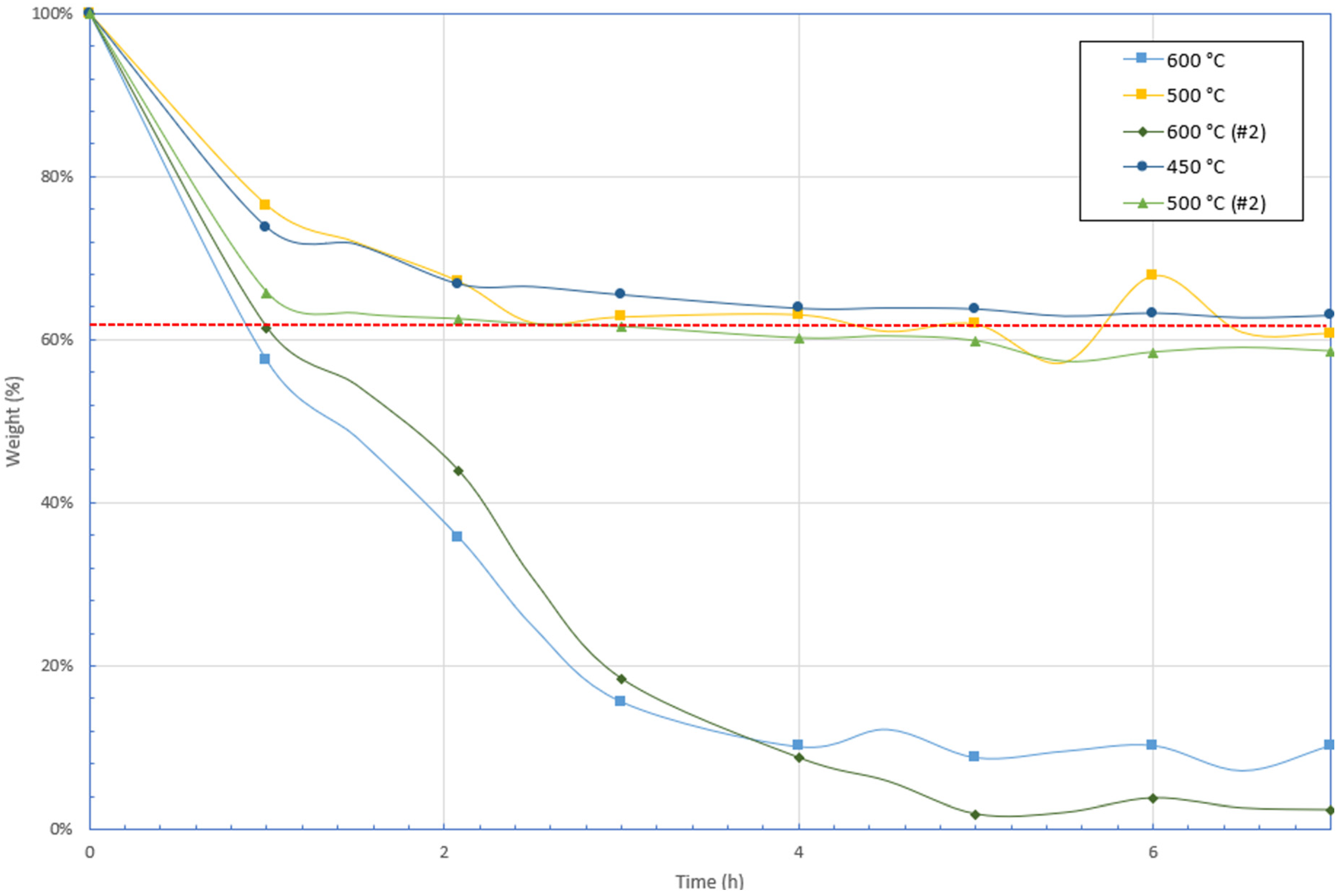
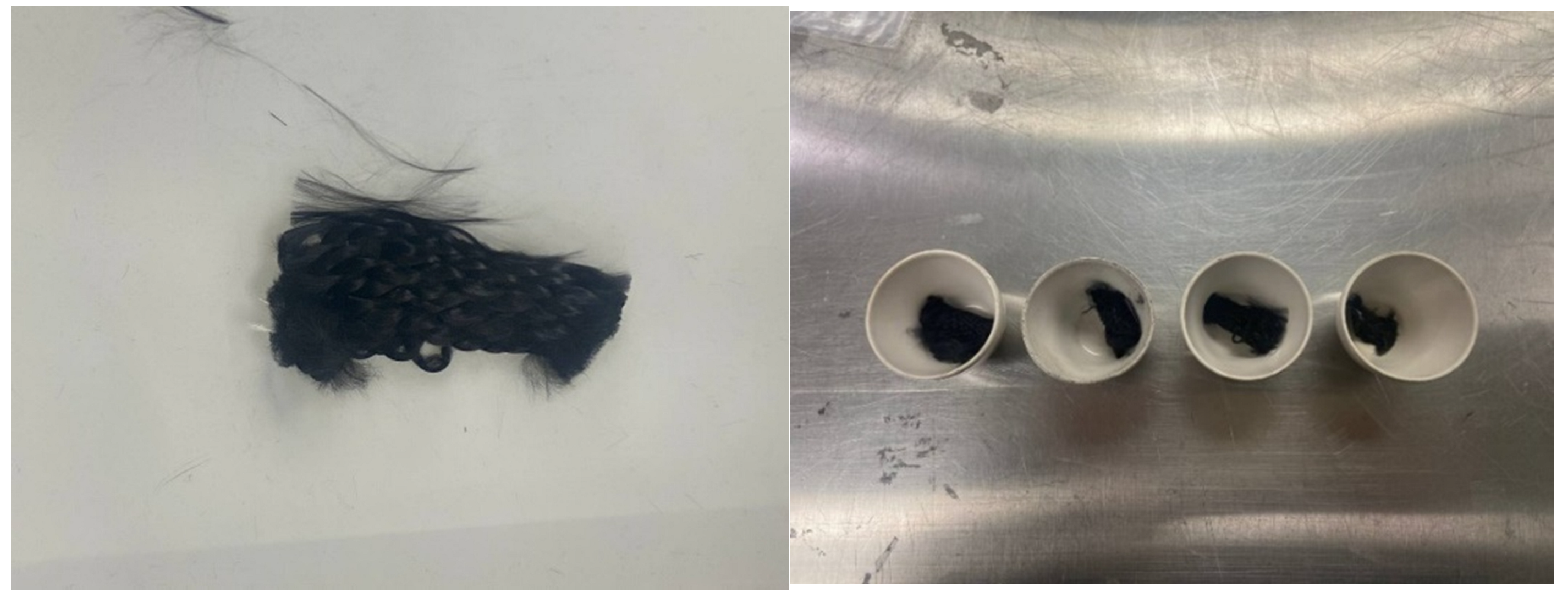
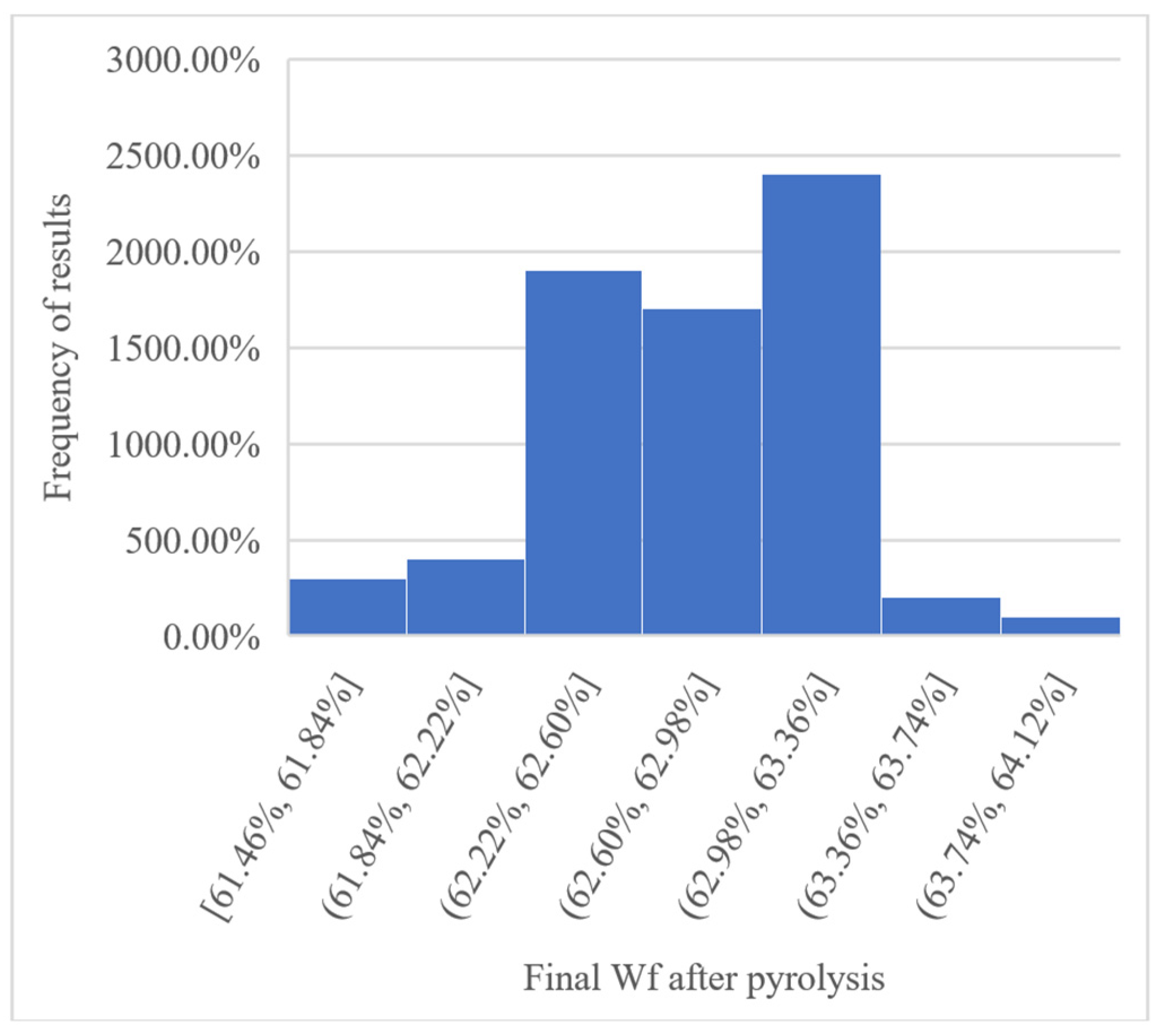
Based on the literature review and initial TGA curves (Figure 1), three temperature levels (450 °C, 500 °C, and 600 °C) were selected for pyrolysis experiments. In each round of the experiments, 12 samples were pyrolyzed. At every 30 min interval, one sample was removed from the oven. The decision to remove one sample from the oven every 30 min provided insights into how the pyrolysis process evolved over time at each temperature. Figure 2 shows the different thermal degradation curves obtained using the red dotted line as the targeted ideal weight fraction. Samples subjected to a temperature of 600 °C (Figure 2) exhibited a significant reduction in weight, particularly in the initial stages. The initial weight loss corresponded to the degradation of the resin at elevated temperatures, whereas the weight loss below the dashed line indicated the combustion of the carbon fibers. The pronounced temperature and subsequent degradation of carbon fibers highlight that 600 °C is an unfavorable choice for the prepreg and leads to considerable fiber loss. At this temperature, the morphology and structure of the fibers underwent noticeable alterations. Figure 3 shows the samples post-pyrolysis at 600 °C, revealing their crumpled and physically damaged appearance. Results from experiment #4, conducted at 450 °C, exhibited a recycling trend. The samples subjected to pyrolysis at 450 °C gradually approach the dashed line in a gentle and slow manner. It took 6 h for these samples to undergo a 37.5% reduction in their initial mass. Pyrolysis experiments at 500 °C were carried out in two sets, corresponding to experiments #2 and #5. Similar to the findings at 450 °C, the final mass loss at 500 °C reached the designated dashed line, signifying the complete removal of the matrix from the samples and the retention of carbon fibers post-pyrolysis. Therefore, both 450 °C and 500 °C are favorable conditions for the pyrolysis of carbon fiber samples, ensuring the complete removal of the matrix from carbon fibers. The distinction between the two scenarios lies in their convergence times. As per the gathered data, the 450 °C samples require 6 h to achieve a 37.5% reduction in initial mass, indicating that 6 h is the optimal duration for the carbon fiber samples to completely shed their matrices at this temperature. Conversely, based on experimental data and Figure 2, the convergence time for pyrolysis at 500 °C is shorter. The effective recovery time, that is, the duration needed to eliminate all matrices from prepreg samples, was 2.5 h at 500 °C. Thus, the most optimal condition for recycling prepreg samples in this study was established as 2.5 h at 500 °C. Following identification of the optimal pyrolysis conditions, the process was replicated over 70 samples measuring 1” × 1” (25.4 mm × 25.4 mm). The average fiber content after pyrolysis under ambient air of the 70 samples at 500 °C for 2.5 h was 62.8%. Figure 4 illustrates the distribution of the final Wf results.

3.3. Properties of Recycled Fibers

Following the identification of the optimal pyrolysis conditions, that is, 2.5 h at 500 °C, optimal pyrolysis conditions were reproduced on larger samples. Recycled fabrics (250 mm × 250 mm) were used to prepare composite plates for further characterization using the VARI process. Various plates were manufactured and tested according to different standards. Table 1 presents the composite plate samples manufactured from recycled fabrics under the optimum pyrolysis conditions established in this study.

3.3.1. Density per ASTM D792 Procedure B and Void Content per ASTM D3171 B

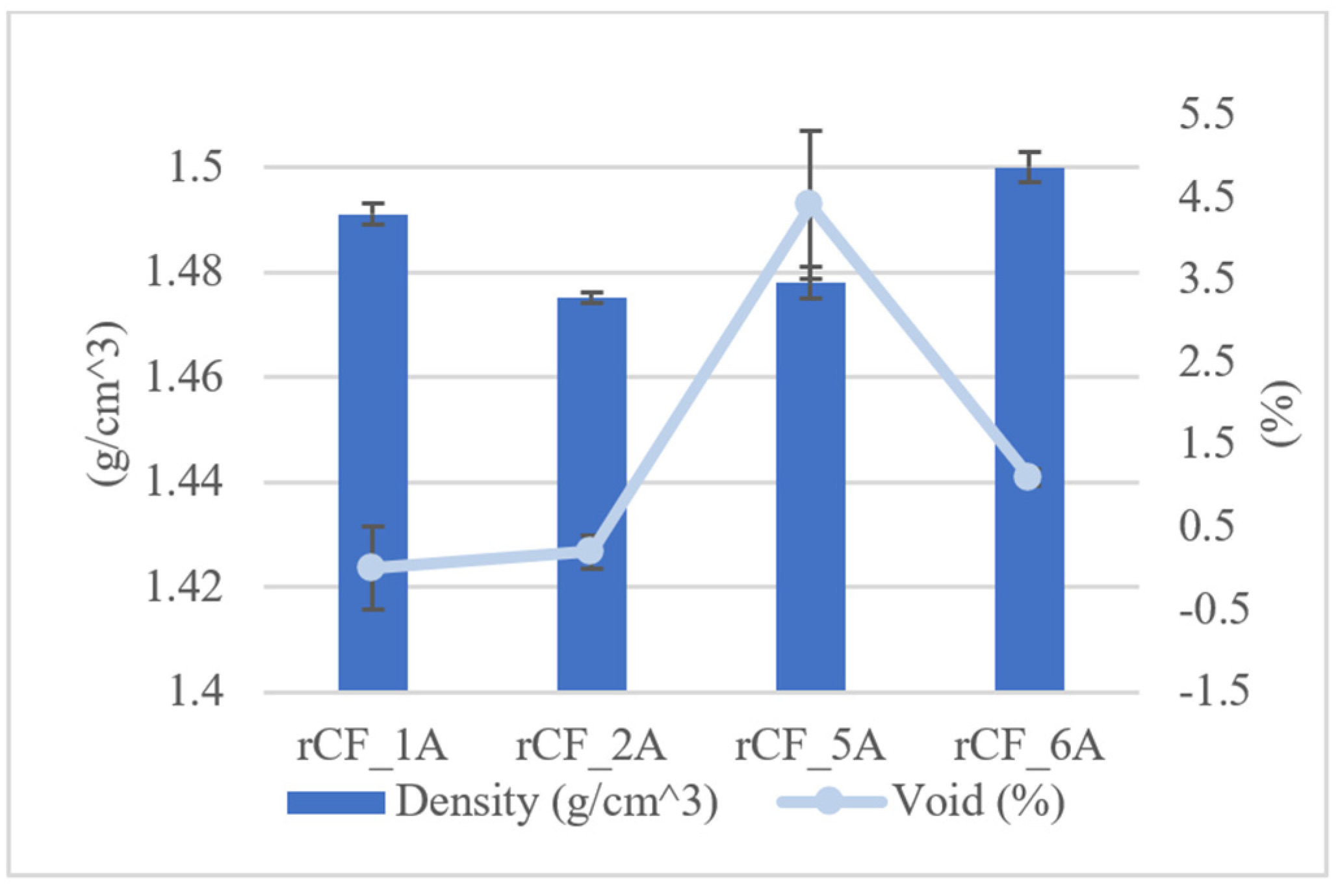
The density and void content were measured on four distinct plates. The results are summarized in Figure 5. The average density was 1.486 g/cm3. The average void content was 1.55%, with a maximum of 5.50%. The dispersion in void-content values was explained by the manufacturing process (VARI method), which is not an automated process and leads to variations in results.

3.3.2. Glass Transition Temperature per ASTM D7028

Three composite plates were used to evaluate the glass transition temperature (Tg) of the recycled carbon-fiber plates. Measurements were performed according to ASTM D7028-07 using a Q800 dynamic mechanical analyzer (TA Instruments, DE, USA). Tests were performed using a frequency of 1Hz, a ramp of 5 °C/min, an amplitude of 0.1%, a dual cantilever set up, and the multi-frequency-strain mode. The average Tg of manufactured plates was 58.25 °C. Tg is a property primarily influenced by the resin, and per the datasheet of the resin system, Tg was 73 °C for the Araldite® LY 8601/Aradur® 8602 System. Therefore, the recovered Tg was 79.8% of the glass transition of the resin system. The decrease in the temperature and the disparity of the results may also be a consequence of the processing method used to manufacture the plates (VARI) and to post-cure the rCF plates. The observed disparity may also be attributed to the non-optimized hardener-to-resin ratio.

3.3.3. Mechanical Properties of rCF Composite Plates

Assessment of the mechanical properties of new materials made of recycled carbon fibers is possible by evaluating the tensile strength, compression strength, shear strength, short-beam shear strength, and flexural strength of rCF-manufactured plates. These values were compared, when possible, with the mechanical properties of vCFs, as identified in the technical datasheet of the material studied. A summary of the samples tested is presented in Table 1. Table 2 shows the obtained values in comparison with the vCF properties and an assessment of the recovery rate for each property. The recovery rate was estimated as the mechanical properties of the recycled carbon fiber divided by the mechanical property of the vCF. Equation (1) shows an example of the calculation of the recovery rate for tensile strength.
R.R.T.S = Average   tensile   strength   of   rCF   plate   ( Mpa ) I n i t i a l   v a l u e   o f   t e n s i l e   s t r e n g t h   ( M p a ) R.R.T.S = ( 663.23 / 905.28 ) × 100 = 73.26 %
Depending on the analyzed property, the average recovery rate was computed to be between 41.82% and 93.45%. The average recovery rate was 67.15%. Several factors may have contributed to the reduction of mechanical properties of rCFs in comparison to vCFs, primarily the manufacturing process, chosen for its cost-effectiveness and utilization of an inexpensive resin during manufacturing.
First, regarding the manufacturing process, various factors can influence fluid dynamics during the resin infusion process. These factors include the bulk permeability of the fabric, flow direction, direction perpendicular to the flow, permeability of fiber tows, and permeability of the distribution media used to enhance the flow within the plane of the composite structure being fabrication [32,33,34,35,36]. The distribution of voids is particularly important, especially in the production of panels using VARI, where the preform initially begins to dry completely and should ideally achieve full saturation with resin. However, owing to fabric architecture, inherent variations in lay-up techniques, and processing methods, there is a high likelihood that certain regions within or between the fiber tows are devoid of resins. Most composite panels or structures consist of multiple layers of fabric stacked together, resulting in voids being distributed not only within the composite plane but also throughout the thickness [34,35,36,37,38]. In the VARI manufacturing processes, there is a variability of ±10% in the void content and thickness gradient, whereas autoclave processes exhibit a lower variability of ±3% for the same properties (void content and thickness gradient) [34,35,36,37,38,39,40,41]. Finally, multiple studies have confirmed that these voids formed during manufacturing have notable implications, as they negatively impact mechanical performance, including flexural strength, compressive strength, and interlaminar shear strength [34,35,36,37,38,39,40,41].
The second reason for such high variability in the recovery rate is explained by the use of a general-purpose resin system. Notably, the datasheet of the initial prepreg that was used for comparison is based on the use of a high-quality resin specifically designed for aerospace applications. Therefore, use of a general-purpose resin instead of the high-grade resin specified in the datasheet of the vCF prepreg explains the differences in some of the results, especially for tests such as interlaminar shear, which are extremely sensitive to the properties of the resin materials. Additionally, the reduction in strength can be explained by surface defects on recycled carbon fibers due to exposure to air at high temperatures. In fact, the inherent surface of PAN-based carbon fibers consists of crystallites that are relatively aligned because of their skin-core structure [42,43,44,45,46]. Therefore, surface defects affecting the inherent surface will affect the alignment of the crystallites and consequently lead to a lower strength resistance of the recycled fiber. This effect was even more pronounced in the compression and intralaminar shear test results, as these defects prevented good load transfer at the interface between the fiber and matrix.
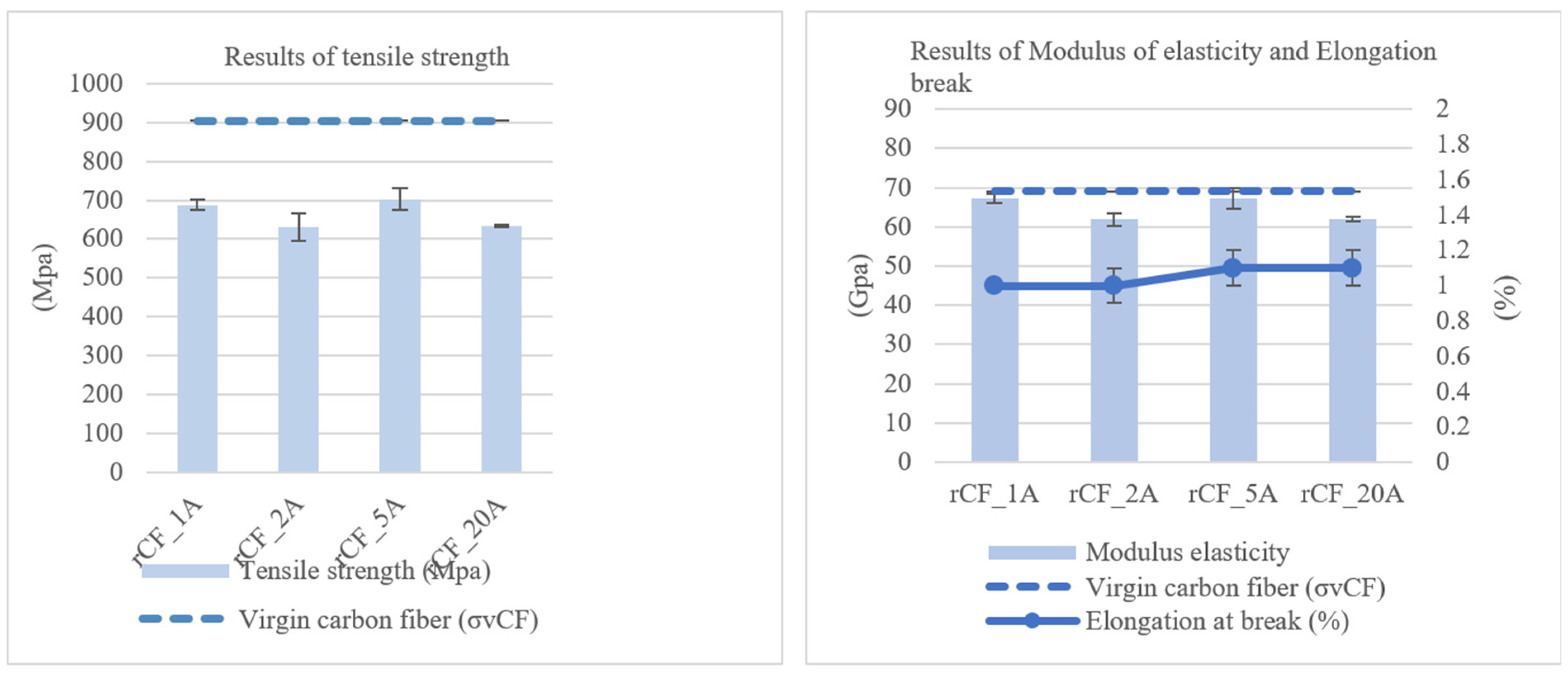
Even with an average recovery rate of 67.15%, the recycled plates exhibited superior performance compared with the metallic and composite materials listed in Table 3, Table 4 and Table 5. The relatively high tensile strength-to-weight ratio makes rCFRPs well-suited for applications where weight is a critical factor. The manufacturing of numerous lightweight and high-strength structures using rCFRPs is feasible. Furthermore, as can be seen from the recovery rate of the modulus results, the method used for recovering carbon fibers in this study effectively preserved the modulus of elasticity. Despite a modest 6.55% decrease in the tensile modulus, the retained value exceeded that of numerous commonly used composites in the industry and was nearly comparable to the modulus of the 6061-T6 aluminum alloy. Figure 6 shows the tensile strengths and tensile moduli of the recycled carbon fiber plates. Table 3, Table 4 and Table 5 provides comparison among various metallic and composite materials, with “rCFRP” denoting the CFRPs manufactured from recycled carbon fibers in this study. Figure 7 presents typical curves for recycled carbon fiber (rCF) reinforced plates subjected to tensile, compression, in-plane shear, short-beam shear, and flexural loading, along with DMA curves illustrating the glass transition temperature.

3.4. Morphology of Recycled Carbon Fibers

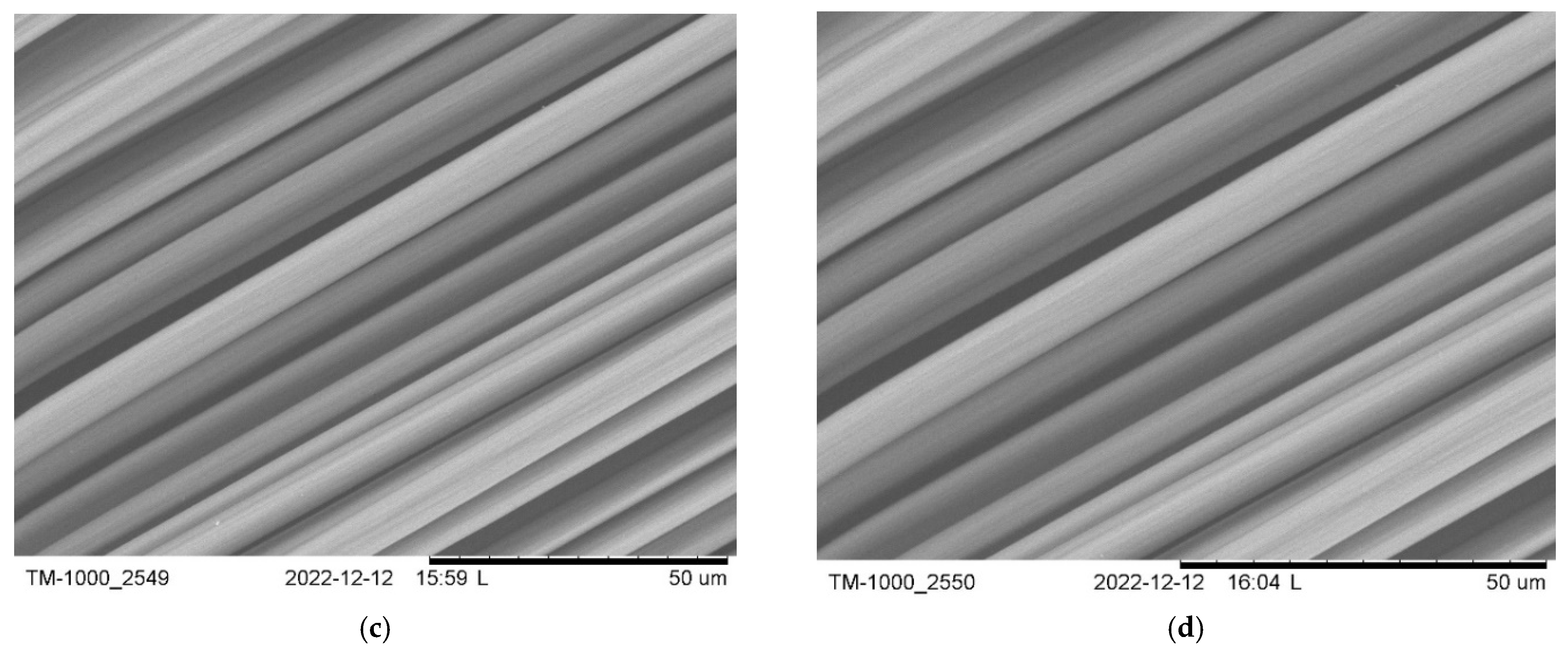
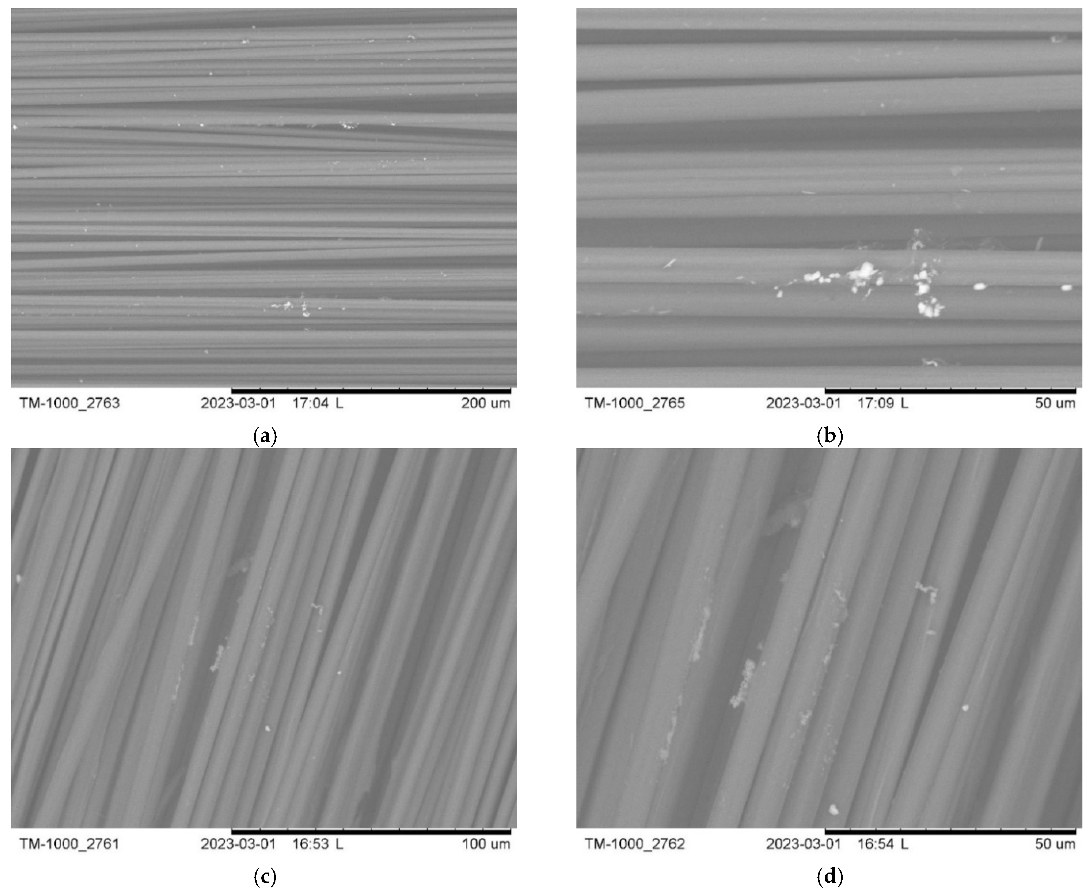
After evaluating the optimal pyrolysis conditions in terms of temperature and time, further scanning electronic microscopy was used to examine the surface morphology of the recovered carbon fibers. Various images at different magnifications were captured from random samples to analyze the surfaces of the recovered carbon fibers. Figure 8 shows some of the SEM images derived from pyrolyzed samples at 500 °C after 2.5 h of pyrolysis. According to the SEM results obtained under optimal conditions, the surfaces of the recovered carbon fibers appeared clean and free of resins. SEM was also used to inspect the surfaces of the carbon fibers recovered under other pyrolysis conditions. As depicted in Figure 9, pyrolysis at 500 °C for 1 h proved inadequate, leaving some residual resins on the fiber surface. Figure 9 shows SEM images of pyrolysis at 450 °C after 3 h, revealing evident traces of resins on the fibers. Consequently, 3 h of pyrolysis at 450 °C was insufficient to eliminate all matrices within the initial prepreg samples.

3.5. Summary of rCFRP Properties

The properties of recycled carbon fiber-reinforced polymer (rCFRP) composites obtained in this study demonstrate the feasibility of an economical and sustainable recycling approach (Table 6). The composite plates manufactured from recovered carbon fibers exhibited a density of 1.486 g/cm3, a void content of 1.55%, and a glass transition temperature of approximately 59.6 °C. These results indicate that the resin infusion process yielded a well-consolidated composite structure with minimal porosity.
Mechanical characterization (Table 2) revealed that the recycled fibers retained a significant portion of their original properties. The tensile strength and modulus of the rCFRP plates reached 73.3% and 93.5% of the values observed for virgin carbon fibers (vCF), respectively. The compressive strength was 50.4% of vCF, while the compressive modulus retained 71.7% of its original value. Additionally, the recycled composite demonstrated a shear strength of 78.7%, a flexural strength of 692.9 MPa, and a shear modulus retention of 46.2%, confirming its suitability for structural applications.
A key factor influencing the mechanical properties of the recycled composite was the resin system used. While the original CFRP utilized a high-performance aerospace-grade resin (CYCOM 5320 8HS T6503k), the recycled plates were fabricated using a cost-effective, general-purpose epoxy resin suitable for the vacuum-assisted resin infusion (VARI) process (Araldite® LY 8601/Aradur® 8602 System). The difference in resin quality contributed to the observed variations in mechanical properties, particularly in interlaminar shear strength and compression performance. Additionally, processing factors such as fiber surface modifications during pyrolysis and void formation inherent to the VARI manufacturing process further impacted property retention.
Nevertheless, when compared to conventional materials such as aluminum alloys and sheet molding compounds (SMCs), rCFRP composites exhibited superior strength-to-weight ratios, making them competitive alternatives for lightweight structural applications.

4. Conclusions

This study evaluated pyrolysis in ambient air as a cost-effective method for recycling CFRP composites. Optimal processing conditions were established at 500 °C for 2.5 h, ensuring efficient fiber recovery while maintaining good mechanical integrity. SEM analysis confirmed that no significant resin or char residues remained on the recovered fibers, demonstrating that additional oxidation steps typically required in inert-atmosphere pyrolysis processes are unnecessary.
The recycled fibers retained promising mechanical properties, recovering 73.3% of the tensile strength and 93.5% of the tensile modulus of virgin carbon fibers. Although some mechanical property reductions were observed—mainly due to the use of a lower-cost, general-purpose resin and the inherent variability of the manufacturing process—the recycled CFRP plates still outperformed several commonly used structural materials, particularly in strength-to-weight ratios.
This study highlights the potential of ambient-air pyrolysis as a practical, economical, and environmentally friendly alternative for CFRP recycling. By leveraging conventional ovens, the method eliminates the need for specialized equipment, broadening the accessibility of CFRP recycling in diverse industrial settings. Future research should focus on fiber surface treatment and refining processing techniques to further enhance mechanical property retention and expand the applicability of recycled CFRP materials in high-performance applications.

Author Contributions

C.D.: investigation, conceptualization, methodology, formal analysis, writing—original draft, validation, approval, project administration, funding acquisition, data analysis. A.J.: experimental work, formal analysis and report of results, review of the article. R.B.: supervision, review, and editing, project administration, funding acquisition, formal analysis, data curation, resources. All authors have read and agreed to the published version of the manuscript.

Funding

This research was funded by the Natural Sciences and Engineering Research Council of Canada (NSERC) and the Ministère de l’Économie et de l’ Innovation (MEI).

Data Availability Statement

The original contributions presented in this study are included in the article. Further inquiries can be directed to the corresponding author.

Acknowledgments

We would like to thank CTT Group, Bombardier Aerospace, and Composites M1 for their valuable support.

Conflicts of Interest

The authors declare that they have no known competing financial interests or personal relationships that could have appeared to influence the work reported in this paper.

References

  1. Rani, M.; Choudhary, P.; Krishnan, V.; Zafar, S. A review on recycling and reuse methods for carbon fiber/glass fiber composites waste from wind turbine blades. Compos. B Eng. 2021, 215, 108768. [Google Scholar] [CrossRef]
  2. He, Y.; Yang, S.; Liu, H.; Shao, Q.; Chen, Q.; Lu, C.; Jiang, Y.; Liu, C.; Guo, Z. Reinforced carbon fiber laminates with oriented carbon nanotube epoxy nanocomposites: Magnetic field assisted alignment and cryogenic temperature mechanical properties. J. Colloid. Interface Sci. 2018, 517, 40–51. [Google Scholar] [CrossRef]
  3. Xing, M.; Li, Z.; Zheng, G.; Du, Y.; Chen, C.; Wang, Y. Recycling of carbon fiber-reinforced epoxy resin composite via a novel acetic acid swelling technology. Compos. B Eng. 2021, 224, 109230. [Google Scholar] [CrossRef]
  4. Utekar, V.K.S.; More, S.N.; Rao, A. Comprehensive study of recycling of thermosetting polymer composites—Driving force, challenges and methods. Compos. B Eng. 2021, 207, 108596. [Google Scholar] [CrossRef]
  5. Anguita, J.V.; Smith, C.T.G.; Stute, T.; Funke, M.; Delkowski, M.; Silva, S.R.P. Dimensionally and environmentally ultra-stable polymer composites reinforced with carbon fibres. Nat. Mater. 2020, 19, 317–322. [Google Scholar] [CrossRef] [PubMed]
  6. Pramanik, A.; Basak, A.K.; Dong, Y.; Sarker, P.K.; Uddin, M.S.; Littlefair, G.; Dixit, A.; Chattopadhyaya, S. Joining of carbon fibre reinforced polymer (CFRP) composites and aluminium alloys—A review. Compos. Part A Appl. Sci. Manuf. 2017, 101, 1–29. [Google Scholar] [CrossRef]
  7. Knappich, F.; Klotz, M.; Schlummer, M.; Wolling, J.; Maurer, A. Recycling process for carbon fiber reinforced plastics with polyamide 6, polyurethane and epoxy matrix by gentle solvent treatment. Waste Manag. 2019, 85, 73–81. [Google Scholar] [CrossRef] [PubMed]
  8. Vieira, D.R.; Vieira, R.K.; Chain, M.C. Strategy and management for the recycling of carbon fiber-reinforced polymers (CFRPs) in the aircraft industry: A critical review. Int. J. Sustain. Dev. World Ecol. 2016, 24, 214–223. [Google Scholar] [CrossRef]
  9. Spini, F.; Bettini, P. End-of-Life wind turbine blades: Review on recycling strategies. Compos. B Eng. 2024, 275, 111290. [Google Scholar] [CrossRef]
  10. Zhao, Q.; Jiang, J.; Li, C.; Li, Y. Efficient recycling of carbon fibers from amine-cured CFRP composites under facile condition. Polym. Degrad. Stab. 2020, 179, 109268. [Google Scholar] [CrossRef]
  11. Zhang, J.; Lin, G.; Vaidya, U.; Wang, H. Past, present and future prospective of global carbon fibre composite developments and applications. Compos. B Eng. 2023, 250, 110463. [Google Scholar] [CrossRef]
  12. Wu, J.; Gao, X.; Wu, Y.; Wang, Y.; Nguyen, T.; Guo, M. Recycling Carbon Fiber from Carbon Fiber-Reinforced Polymer and Its Reuse in Photocatalysis: A Review. Polymers 2023, 15, 170. [Google Scholar] [CrossRef] [PubMed]
  13. Wang, Y.; Cui, X.; Ge, H.; Yang, Y.; Wang, Y.; Zhang, C.; Li, J.; Deng, T.; Qin, Z.; Hou, X. Chemical recycling of carbon fiber reinforced epoxy resin composites via selective cleavage of the carbon–nitrogen bond. ACS Sustain. Chem. Eng. 2015, 3, 3332–3337. [Google Scholar] [CrossRef]
  14. Pietroluongo, M.; Padovano, E.; Frache, A.; Badini, C. Mechanical recycling of an end-of-life automotive composite component. Sustain. Mater. Technol. 2020, 23, e00143. [Google Scholar] [CrossRef]
  15. Vincent, G.A.; de Bruijn, T.A.; Wijskamp, S.; Rasheed, M.I.A.; Van Drongelen, V.; Akkerman, R. Shredding and sieving thermoplastic composite scrap: Method development and analyses of the fibre length distributions. Compos. B Eng. 2019, 176, 107197. [Google Scholar] [CrossRef]
  16. Mazzocchetti, L.; Benelli, T.; D’Angelo, E.; Leonardi, C.; Zattini, G.; Giorgini, L. Validation of carbon fibers recycling by pyro-gasification: The influence of oxidation conditions to obtain clean fibers and promote fiber/matrix adhesion in epoxy composites. Compos. Part A Appl. Sci. Manuf. 2018, 112, 504–514. [Google Scholar] [CrossRef]
  17. Kim, K.W.; Lee, H.M.; Jan, J.H.; Chung, D.C.; An, K.H.; Kim, B.J. Recycling and characterization of carbon fibers from carbon fiber reinforced epoxy matrix composites by a novel super-heated-steam method. J. Environ. Manag. 2017, 203, 872–879. [Google Scholar] [CrossRef]
  18. Kim, D.H.; Lee, M.; Goh, M. Enhanced and eco-friendly recycling of carbon-fiber-reinforced plastics using water at ambient pressure. ACS Sustain. Chem. Eng. 2020, 8, 2433–2440. [Google Scholar] [CrossRef]
  19. He, D.; Soo, V.K.; Kim, H.C.; Compston, P.; Doolan, M. Comparative life cycle energy analysis of carbon fibre pre-processing, processing and post-processing recycling methods. Resour. Conserv. Recycl. 2020, 158, 104794. [Google Scholar] [CrossRef]
  20. Stróżyk, M.A.; Muddasar, M.; Conroy, T.J.; Hermansson, F.; Janssen, M.; Svantrom, M.; Frank, E.; Culebras, M.; Collins, M.N. Decreasing the environmental impact of carbon fibre production via microwave carbonisation enabled by self-assembled nanostructured coatings. Adv. Compos. Hybrid. Mater. 2024, 7, 39. [Google Scholar] [CrossRef]
  21. Mainka, H.; Tager, O.; Korner, E.; Hilfert, L.; Busse, S.; Edelmann, F.T.; Herrmann, A.S. Lignin—An alternative precursor for sustainable and cost-effective automotive carbon fiber. J. Mark. Res. 2015, 4, 283–296. [Google Scholar] [CrossRef]
  22. Zhang, J.; Chevali, V.; Wang, H.; Wang, C. Current status of carbon fibre and carbon fibre composites recycling. Compos. B Eng. 2020, 193, 108053. [Google Scholar] [CrossRef]
  23. Meyer, L.O.; Schulte, K.; Grove-Nielsen, E. CFRP-Recycling Following a Pyrolysis Route: Process Optimization and Potentials. J. Compos. Mater. 2009, 43, 1121–1132. [Google Scholar] [CrossRef]
  24. Colucci, G.; Ostrovskaya, O.; Frache, A.; Martorana, B.; Badini, C. The effect of mechanical recycling on the microstructure and properties of PA66 composites reinforced with carbon fibers. J. Appl. Polym. Sci. 2015, 132, 42275. [Google Scholar] [CrossRef]
  25. Abdou, T.R.; Junior, A.B.; Espinosa, D.; Tenório, J. Recycling of polymeric composites from industrial waste by pyrolysis: Deep evaluation for carbon fibers reuse. Waste Manag. 2021, 120, 1–9. [Google Scholar] [CrossRef]
  26. Naqvi, S.R.; Mysore Prabhakara, H.; Bramer, E.A.; Dierkes, W.; Akkerman, R.; Brem, G. A critical review on recycling of end-of-life carbon fibre/glass fibre reinforced composites waste using pyrolysis towards a circular economy. Resour. Conserv. Recycl. 2018, 136, 118–129. [Google Scholar] [CrossRef]
  27. Meng, F.; Olivetti, E.A.; Zhao, Y.; Chang, J.C.; Pickering Stephen, J.; Mckechnie, J. Comparing Life Cycle Energy and Global Warming Potential of Carbon Fiber Composite Recycling Technologies and Waste Management Options. ACS Sustain. Chem. Eng. 2018, 6, 9854–9865. [Google Scholar] [CrossRef]
  28. Dong, P.A.V.; Azzaro-Pantel, C.; Cadene, A.-L. Economic and environmental assessment of recovery and disposal pathways for CFRP waste management. Resour. Conserv. Recycl. 2018, 133, 63–75. [Google Scholar] [CrossRef]
  29. Hadigheh, S.A.; Wei, Y.; Kashi, S. Optimisation of CFRP composite recycling process based on energy consumption, kinetic behaviour and thermal degradation mechanism of recycled carbon fibre. J. Clean. Prod. 2021, 292, 125994. [Google Scholar] [CrossRef]
  30. Chen, P.-Y.; Feng, R.; Xu, Y.; Zhu, J.-H. Recycling and Reutilization of Waste Carbon Fiber Reinforced Plastics: Current Status and Prospects. Polymers 2023, 15, 3508. [Google Scholar] [CrossRef]
  31. Kim, H.-H.; Kim, B.-J. Recovery of carbon fibers from carbon fiber-reinforced epoxy-isophorone diamine composites via step thermolysis. Compos. B Eng. 2023, 260, 110757. [Google Scholar] [CrossRef]
  32. Bard, S.; Demleitner, M.; Weber, R.; Zeiler, R.; Altstadt, V. Effect of curing agent on the compressive behavior at elevated test temperature of carbon fiber-reinforced epoxy composites. Polymers 2019, 11, 943. [Google Scholar] [CrossRef] [PubMed]
  33. Behniafar, H.; Nazemi, M.K. Effect of amine-functionalized silica nanoparticles on thermal and mechanical behaviors of DGEBA/IPD epoxy networks. Polym. Bull. 2017, 74, 3739–3749. [Google Scholar] [CrossRef]
  34. Kumar, A.; Kumar, D. Vacuum assisted resin transfer Moulding process review and variability analysis using Taguchi optimization technique. Mater. Today Proc. 2022, 50, 1472–1479. [Google Scholar] [CrossRef]
  35. Kuentzer, N.; Simacek, P.; Advani, S.G.; Walsh, S. Correlation of void distribution to VARTM manufacturing techniques. Compos. Part A Appl. Sci. Manuf. 2007, 38, 802–813. [Google Scholar] [CrossRef]
  36. Liu, L.; Zhang, B.-M.; Wang, D.-F.; Wu, Z.-J. Effects of cure cycles on void content and mechanical properties of composite laminates. Compos. Struct. 2006, 73, 303–309. [Google Scholar] [CrossRef]
  37. Hernández, S.; Sket, F.; Molina-Aldareguı’a, J.M.; González, C.; Llorca, J. Effect of curing cycle on void distribution and interlaminar shear strength in polymermatrix composites. Compos. Sci. Technol. 2011, 71, 1331–1341. [Google Scholar] [CrossRef]
  38. Hao, W.; Huang, Z.; Xu, Y.; Zhao, G.; Chen, H.; Fang, D. Acoustic emission characterization of tensile damage in 3D braiding composite shafts. Polym. Test. 2020, 81, 106176. [Google Scholar] [CrossRef]
  39. Agius, S.L.; Magniez, K.J.V.; Fox, B.L. Cure behaviour and void development within rapidly cured out-of-autoclave composites. Compos. Part B Eng. 2013, 47, 230–237. [Google Scholar] [CrossRef]
  40. Saenz-Castillo, D.; Martín, M.I.; Calvo, S.; Rodriguez-Lence, F.; Güemes, A. Effect of processing parameters and void content on mechanical properties and NDI of thermoplastic composites. Compos. Part A Appl. Sci. Manuf. 2019, 121, 308–320. [Google Scholar] [CrossRef]
  41. Agius, S.L.; Fox, B.L. Rapidly cured out-of-autoclave laminates: Understanding and controlling the effect of voids on laminate fracture toughness. Compos. Part A Appl. Sci. Manuf. 2015, 73, 186–194. [Google Scholar] [CrossRef]
  42. Swarup, S. A comparative study of bisphenol-A, hydantoin and cyanuric acid based epoxy resins using XRD. Mater. Sci. Appl. 2011, 2, 1516–1519. [Google Scholar] [CrossRef]
  43. Bennett, S.C.; Johnson, D.J.; Johnson, W. Strength-structure relationships in PAN-based carbon fibres. J. Mater. Sci. 1983, 18, 3337–3347. [Google Scholar] [CrossRef]
  44. Sui, X.; Xu, Z.; Hu, C.; Chen, L.; Liu, L.; Kuang, L. Microstructure evolution in γ-irradiated carbon fibers revealed by a hierarchical model and Raman spectra from fiber section. Compos. Sci. Technol. 2016, 130, 46–52. [Google Scholar] [CrossRef]
  45. Zhou, G.; Byun, J.H.; Lee, S.B.; Yi, J.W.; Lee, W.; Lee, S.K. Nano structural analysis on stiffening phenomena of PAN-based carbon fibers during tensile deformation. Carbon N. Y. 2014, 76, 232–239. [Google Scholar] [CrossRef]
  46. Liu, X.; Zhu, C.; Guo, J.; Liu, Q.; Dong, H.; Gu, Y. Nanoscale dynamic mechanical imaging of the skin-core difference: From PAN precursors to carbon fibers. Mater. Lett. 2014, 128, 417–420. [Google Scholar] [CrossRef]
  47. Mallick, P.K. Fiber-Reinforced Composites: Materials, Manufacturing, and Design, 3rd ed.; CRC Press: Boca Raton, FL, USA, 2007; 638p. [Google Scholar]
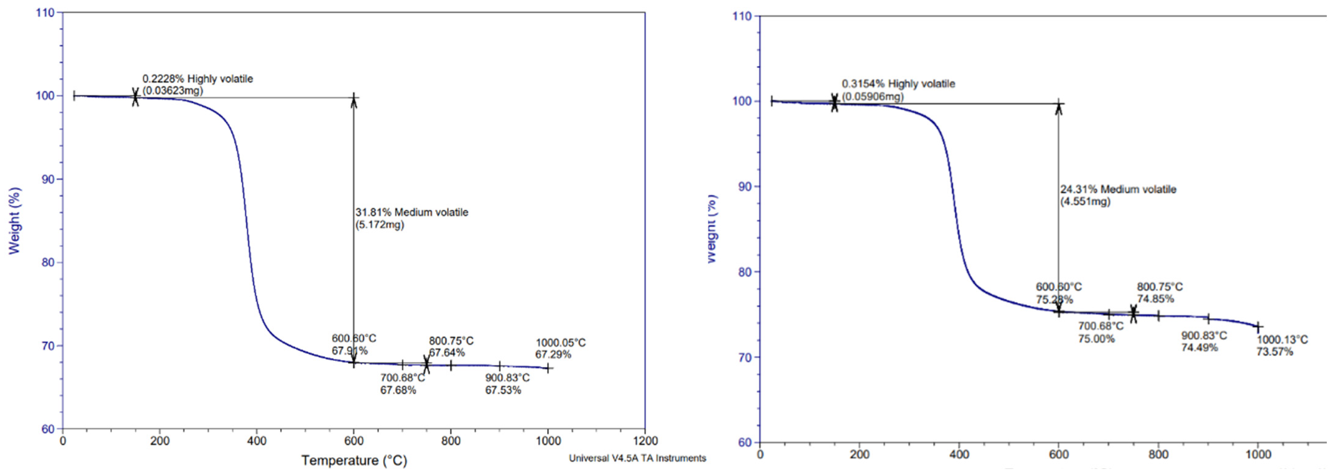
Figure 1. Thermogravimetric analysis (TGA) of initial prepreg sample. Both left and right diagrams are obtained under nitrogen atmosphere.
Fibers 13 00058 g001
Figure 2. Comparative pyrolysis results. The dotted red line corresponds to the optimum fiber weight fraction (Wf = 62.5%) of the prepregs as determined by ASTM D3171 and the results are compared with this value.
Fibers 13 00058 g002
Figure 3. Samples after pyrolysis under 600 °C.
Fibers 13 00058 g003
Figure 4. Frequency of obtained Wf results for pyrolysis at 500 °C for 2.5 h.
Fibers 13 00058 g004
Figure 5. Results of density and void content.
Fibers 13 00058 g005
Figure 6. Tensile strength results (left) and modulus of elasticity (right) of recycled carbon fiber (rCF) reinforced plates.
Fibers 13 00058 g006
Figure 7. Typical curves obtained for recycled carbon fiber reinforced (rCF) plates. (a) Tensile stress–strain curve of rCF 1A; (b) compressive stress–strain curve of rCF 21A; (c) in-plane shear stress–strain curve of rCF 27A; (d) interlaminar shear stress–strain curve of rCF 5A; (e) flexural strength curve of rCF 1A; (f) glass transition temperature curve of rCF 5A.
Fibers 13 00058 g007aFibers 13 00058 g007b
Figure 8. SEM images for samples pyrolyzed at 500 °C for 2.5 h. (a) X30, (b) X500, (c) X1500, (d) X1800.
Fibers 13 00058 g008aFibers 13 00058 g008b
Figure 9. SEM images for pyrolyzed samples: (a) 1 h @ 500 °C-X500, (b) 1 h @ 500 °C-X1800, (c) 3 h @ 450 °C-X500, and (d) 3 h @ 450 °C-X1800.
Fibers 13 00058 g009
Table 1. Sample identification and summary of experimental plan presented in this study.
Plate IDNumber of PliesAverage Thickness (mm)ASTM D792ASTM D3171ASTM D7028ASTM D3039ASTM D6641ASTM D5379ASTM D2344ASTM D790
rCF_1A82.99XXXX X
rCF_2A *83.14XXXX X
rCF_5A41.41XXXX X
rCF_6A41.41XX
rCF_20A41.48 X
rCF_21A44.12 X
rCF_27A83.74 X
Note *: Sample rCF_2A was burned as the post-cure was performed at 180 °C for 3 h instead of 80 °C for 3 h.
Table 2. Recovery rate (%) of the different mechanical properties of the rCF in comparison to the vCF composite plate.
IDAverage Value of rCFRP (Mpa)Average Value of rCFRP (ksi)Average Value of vCF (ksi)Average Value of vCF (Mpa)Recovery Rate in %
Tensile strength663.2396.19131.3905.2873.26%
Tensile modulus64.56 × 1039.36 × 10310.02 × 10369.09 × 10393.45%
Compressive strength378.0054.82108.8750.1550.39%
Compressive modulus45.40 × 1036.58 × 1039.18 × 10363.29 × 10371.73%
Shear strength45.006.538.2957.1678.73%
Shear modulus2.58 × 1030.37 × 1030.81 × 1035.58 × 10346.20%
Short beam strength34.404.9911.9382.2541.82%
Table 3. Comparison of tensile strength of some metallic materials and rCFRP.
MaterialSAE 1010 Steel6061-T6 Aluminum AlloyCFRP
(Quasi-Isotropic)
Sheet Molding Compound (Isotropic)rCFRP
Tensile strength (MPa)365 *310 *579 *164 *663
* Values were obtained from [47].
Table 4. Comparison between tensile strength-to-weight ratio of metallic material and rCFRP.
MaterialSAE 1010 Steel6061-T6 Aluminum AlloyCFRP (Quasi-Isotropic)SMC Composite (Isotropic)rCFRP
Tensile strength-to-weight ratio (103 m)4.72 *11.7 *38 *8.9 *42.4
* Values were obtained from [47].
Table 5. Comparison of modulus of elasticity of some metallic materials and rCFRP.
Material6061-T6 Aluminum AlloyE-Glass Fiber-Epoxy Matrix (UD)CFRP
(Quasi-Isotropic)
SMC Composite (Isotropic)rCFRP
Modulus (GPa)68.9 *39.3 *45.5 *15.8 *64.55
* Values were obtained from [47].
Table 6. Properties of the manufactured plates from recovered CFs of this study.
PropertiesUnitValue
Densityg/cm31.486
Void content%1.55
Glass transition temperature°C59.6
Tensile strengthMPa663.23
Tensile modulusGPa64.56
Tensile elongation at break%1.06
Compressive strengthMPa378
Compressive modulusGPa45.4
Flexural strengthMPa692.9
Flexural modulusGPa38.26
Maximum flexural deformation%1.6
Shear strengthMPa45
Maximum shear deformation%5
Shear modulusMPa2580
Short-beam strengthMPa34.4
Disclaimer/Publisher’s Note: The statements, opinions and data contained in all publications are solely those of the individual author(s) and contributor(s) and not of MDPI and/or the editor(s). MDPI and/or the editor(s) disclaim responsibility for any injury to people or property resulting from any ideas, methods, instructions or products referred to in the content.