
Fiber/Free-Space Optics with Open Radio Access Networks Supplements the Coverage of Millimeter-Wave Beamforming for Future 5G and 6G Communication

 ,
,  , ,
, , 
Abstract
Highlights
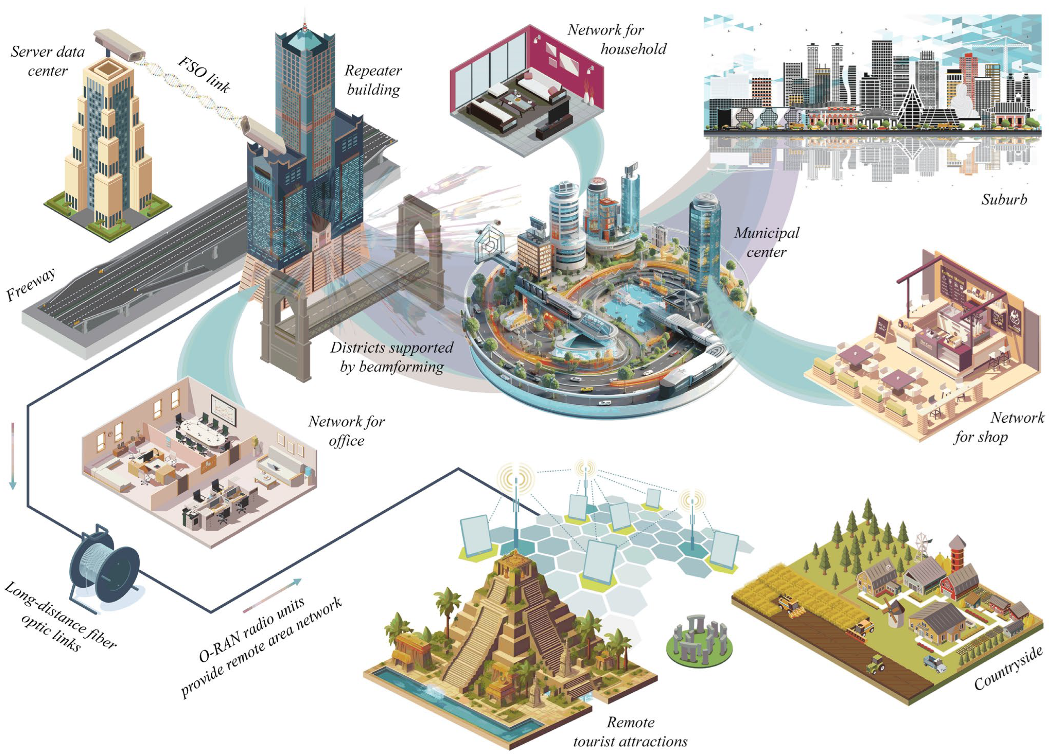
- Fiber and FSO technology can be effectively integrated with O-RAN and deployed in practical applications. The advantages of FSO include its ability to transcend physical barriers, thereby enhancing real-world communication capabilities.
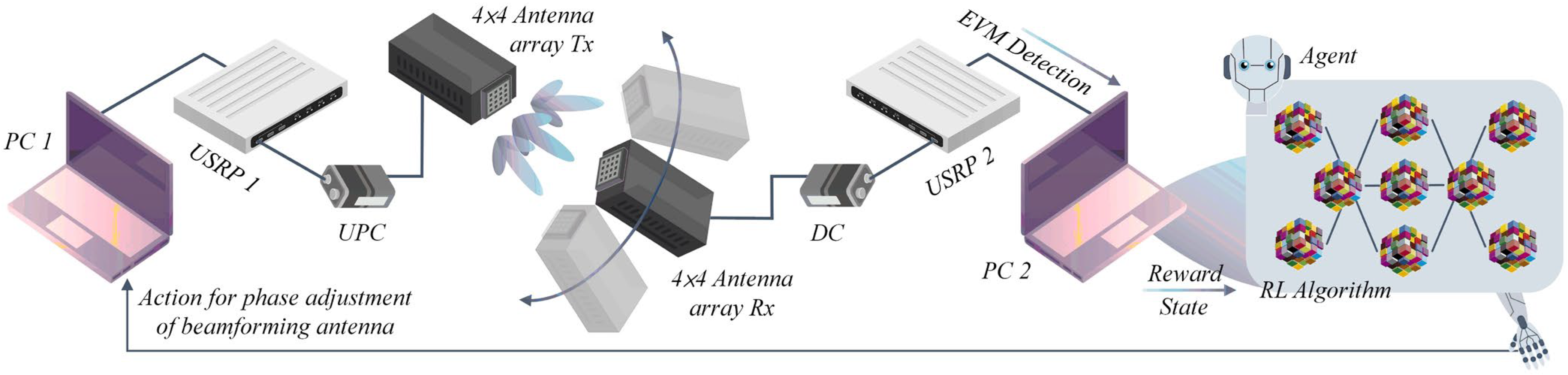
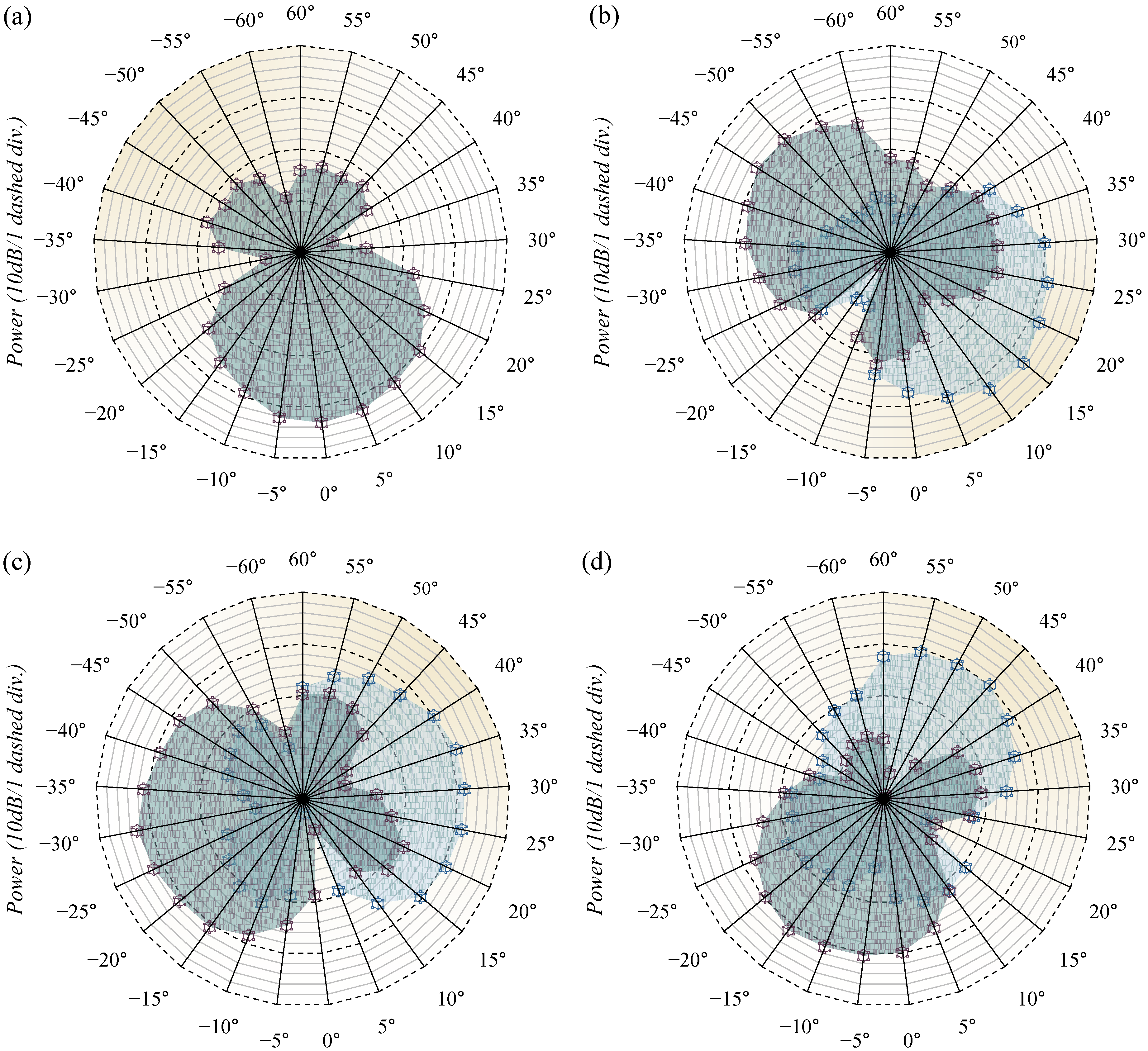
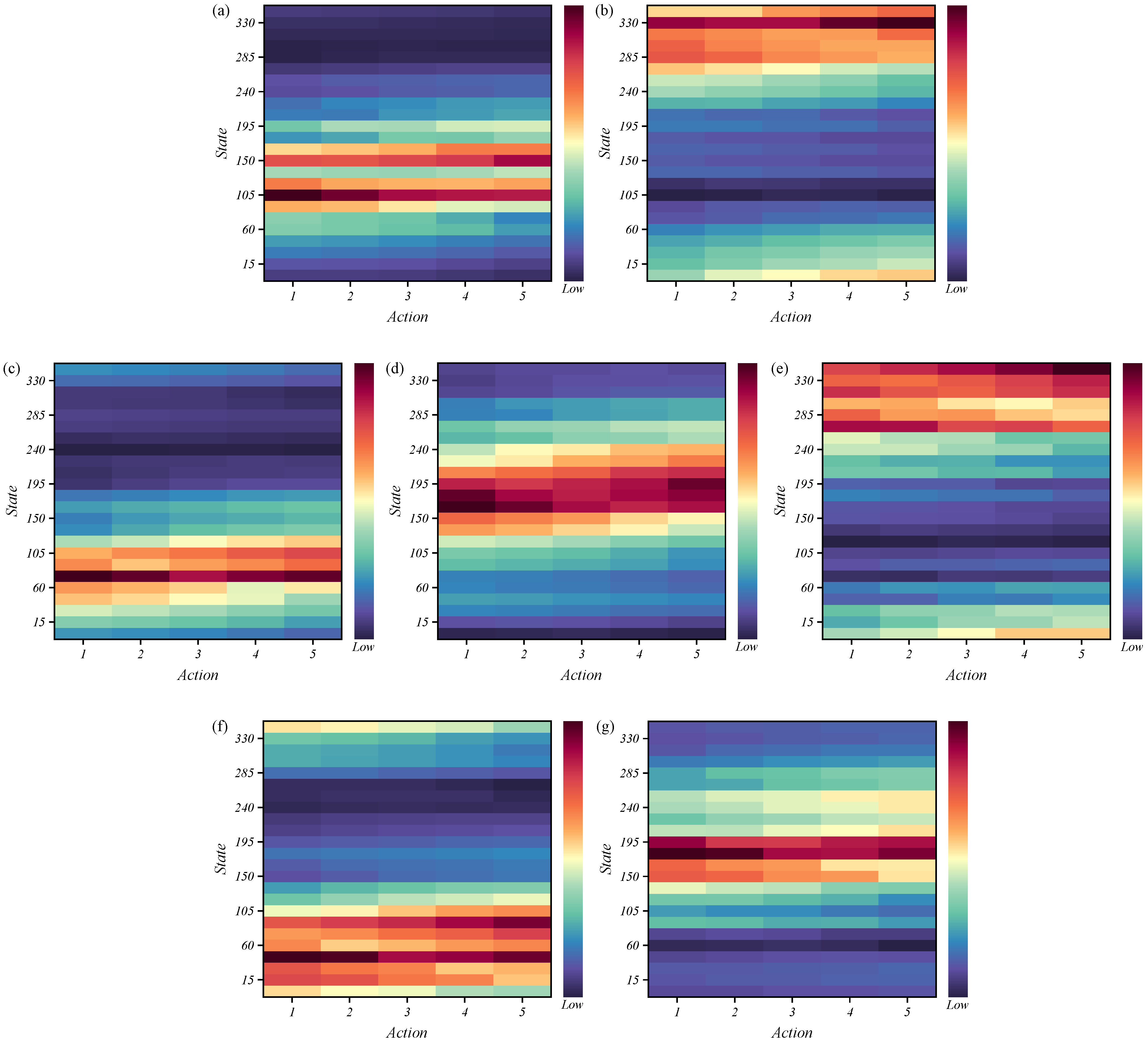
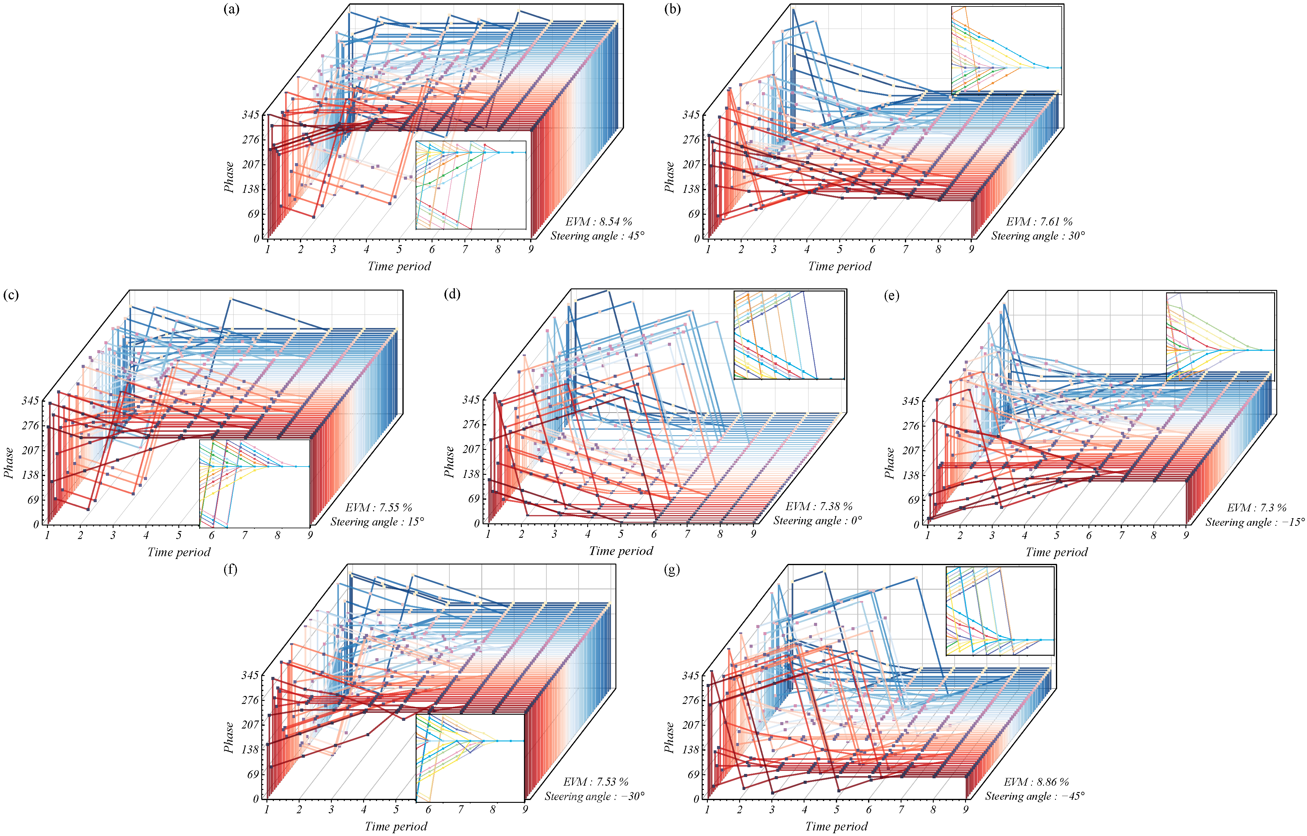
- The mmW beamforming capabilities of array antennas can be enhanced by employing reinforcement learning techniques to optimize network resource allocation for signal reception at the receiver end.
- When integrated with fiber and FSO, O-RAN antennas can be strategically deployed in underserved or remote regions that are beyond the reach of traditional mmW beamforming technology. This approach facilitates a more equitable distribution of network resources while effectively reducing the costs associated with future 5G and 6G communication infrastructures.
- Both FSO and O-RAN antennas can be strategically positioned, enabling the adjustment of their locations in response to short-term network demands. This capability enhances the overall flexibility of the network infrastructure.
Abstract
1. Introduction
2. Adaptive Beam Alignment Using RL
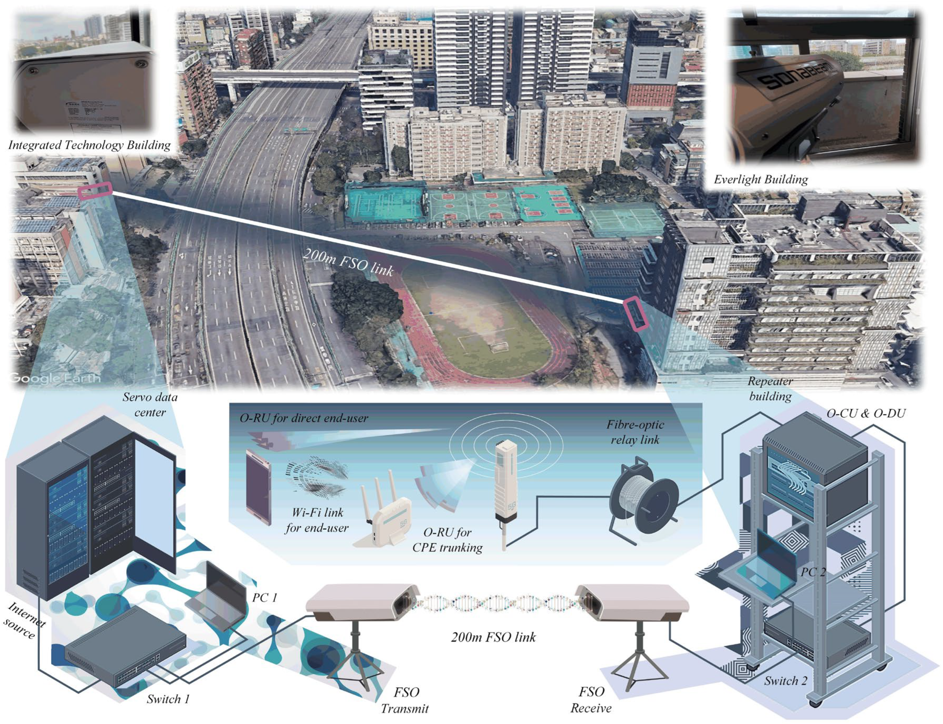
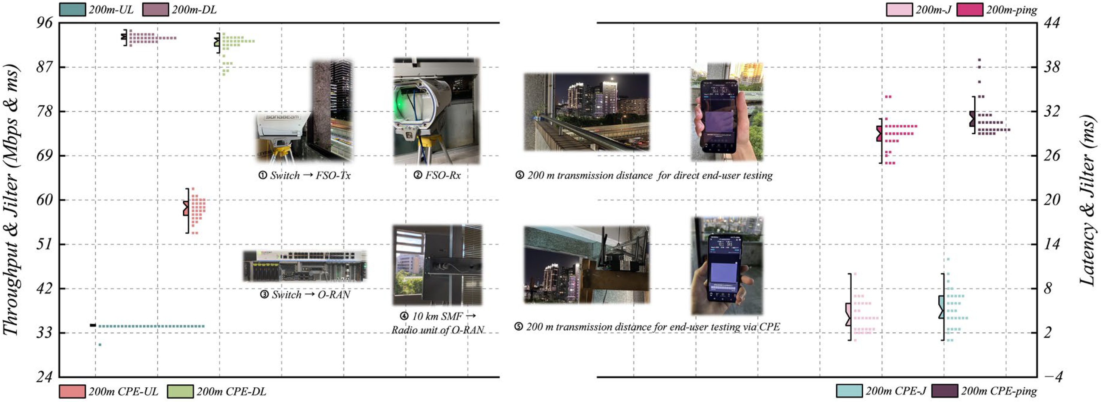
3. O-RAN with 200 m FSO Link
3.1. FSO Setup and Background
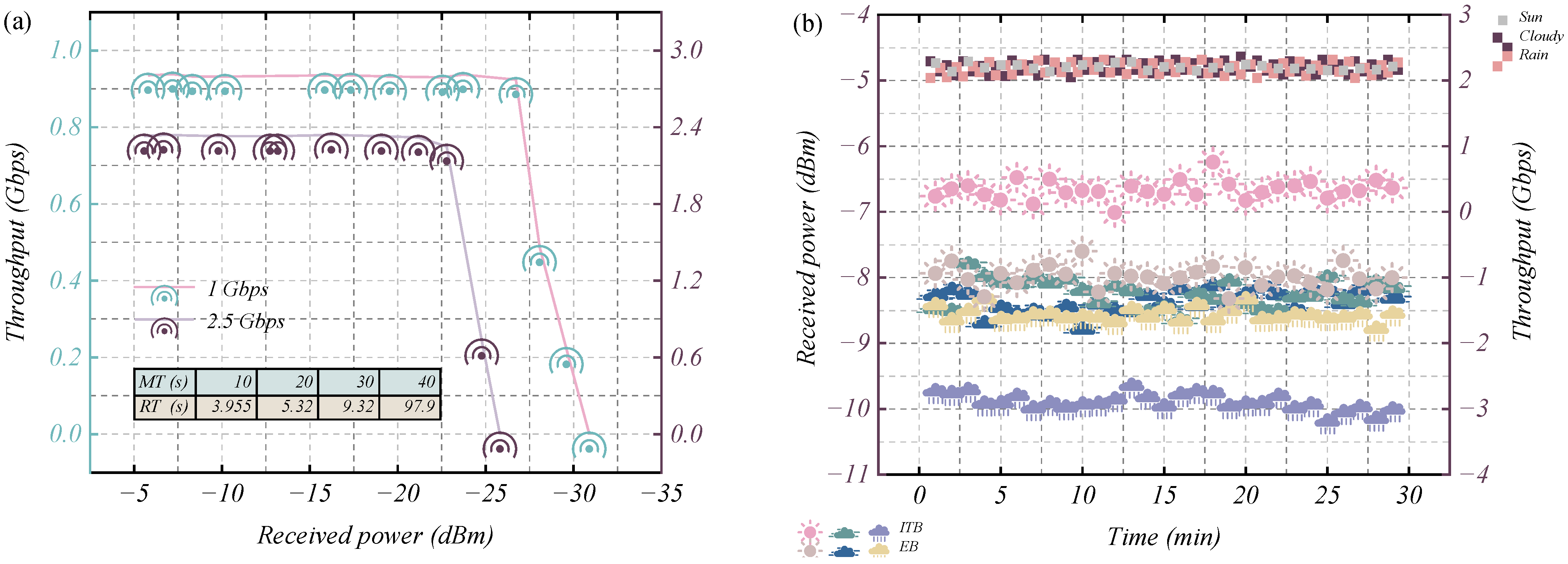
3.2. Preoperation and Measurement of 200 m FSO Link Erection
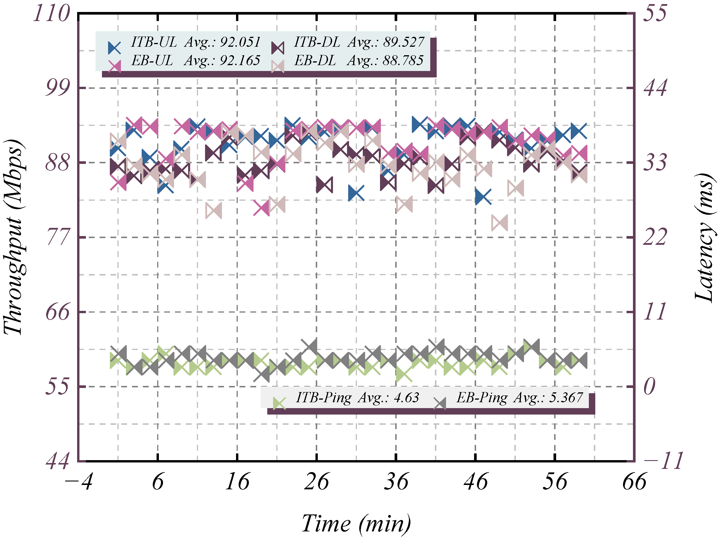
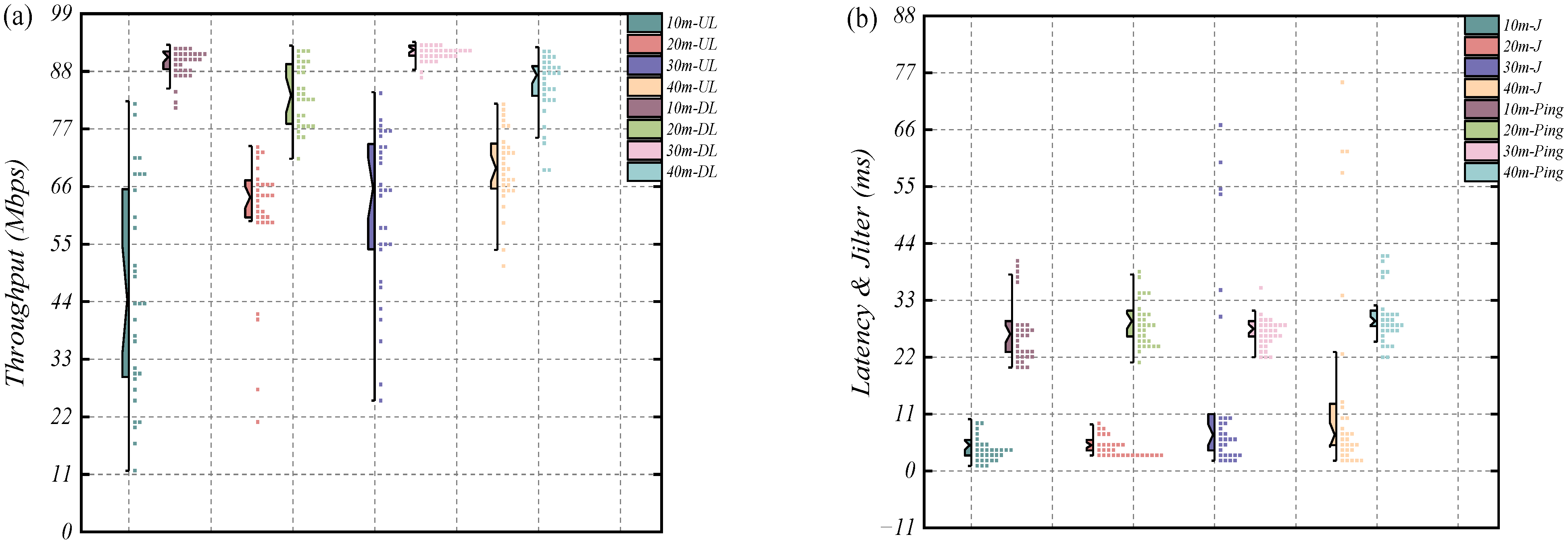
3.3. The 200 m FSO Link Backhaul for O-RAN with 4 m Fronthaul for Indoor Network
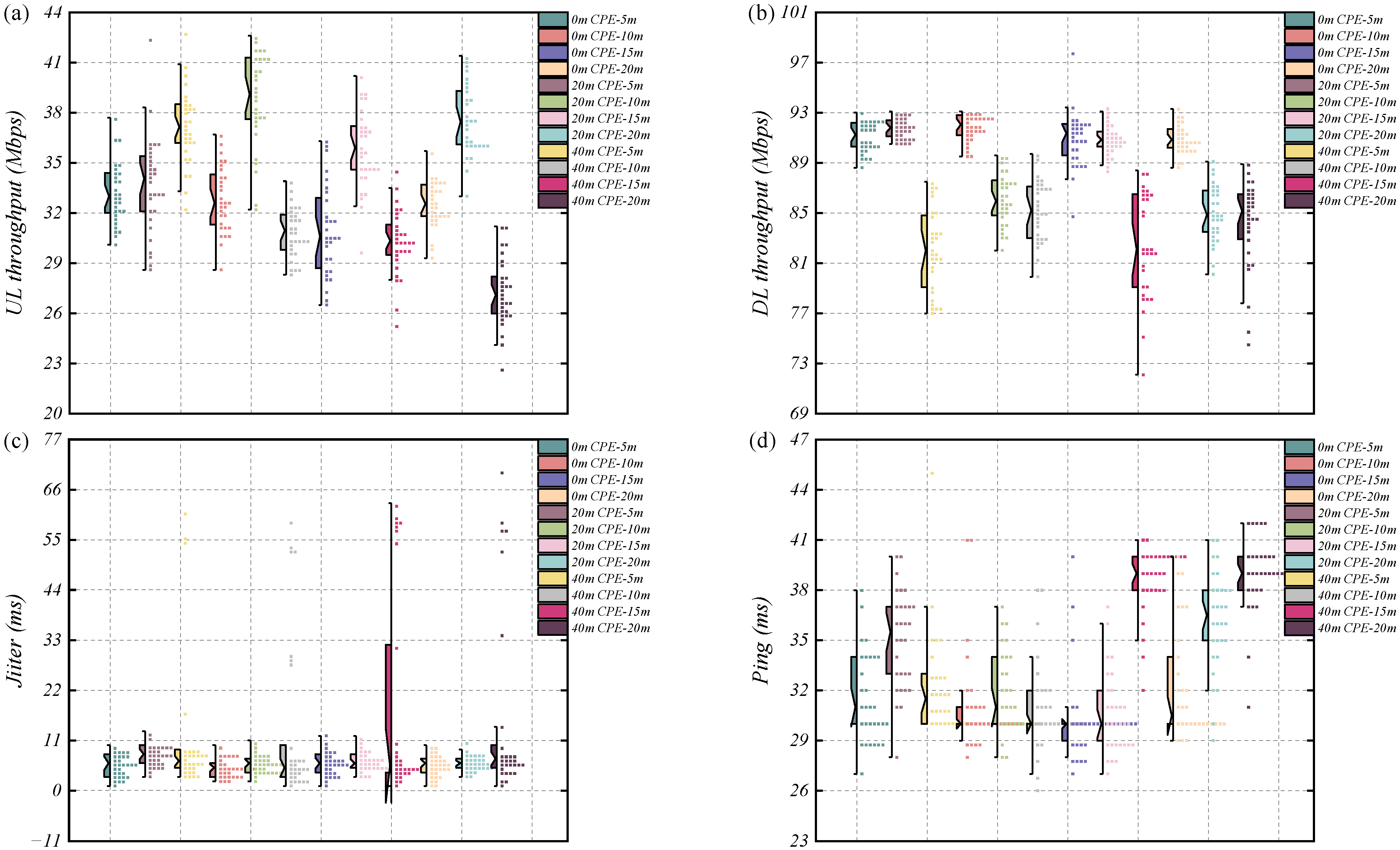
3.4. The 200 m FSO Link Backhaul for O-RAN with 10 km Fronthaul for Outdoor Network
4. Conclusions
Author Contributions
Funding
Institutional Review Board Statement
Informed Consent Statement
Data Availability Statement
Conflicts of Interest
References
- Winzer, P.J.; Neilson, D.T.; Chraplyvy, A.R. Fiber-optic transmission and networking: The previous 20 and the next 20 years. Opt. Express 2018, 26, 24190–24239. [Google Scholar] [PubMed]
- Celik, A.; Romdhane, I.; Kaddoum, G.; Eltawil, A.M. A top-down survey on optical wireless communications for the internet of things. IEEE Commun. Surv. Tutor. 2022, 25, 1–45. [Google Scholar]
- Fayad, A.; Cinkler, T.; Rak, J. 5G/6G optical fronthaul modeling: Cost and energy consumption assessment. J. Opt. Commun. Netw. 2023, 15, D33–D46. [Google Scholar]
- Pinto, F.B.F.; Carneiro de Souza, L.; Andrade, T.P.V.; Lima, E.S.; Silva, L.G.; Portelinha, F.M.; Anderson, E.L.; Cerqueira, S.A. Power-over-fiber-based optical wireless communication systems towards 6G. J. Opt. Commun. Netw. 2024, 16, D86–D95. [Google Scholar]
- Lee, M.C.; Chang, C.H.; Huang, G.J.; Liou, C.W. Hybrid tree-and-multiple-ring radio-over-fiber transmission system for a 5G network in metropolitan areas. J. Opt. Commun. Netw. 2023, 15, 765–775. [Google Scholar]
- Zhu, P.; Yoshida, Y.; Kanno, A.; Kitayama, K.I. DSP-enhanced radio-over-fiber technologies for 5G-and-beyond wired-wireless convergence. J. Opt. Commun. Netw. 2022, 14, 595–605. [Google Scholar]
- Bartsiokas, I.A.; Gkonis, P.K.; Kaklamani, D.I.; Venieris, I.S. A federated learning-based resource allocation scheme for relaying-assisted communications in multicellular next generation network topologies. Electronics 2024, 13, 390. [Google Scholar] [CrossRef]
- Ali, R.; Zikria, Y.B.; Garg, S.; Bashir, A.K.; Obaidat, M.S.; Kim, H.S. A federated reinforcement learning framework for incumbent technologies in beyond 5G networks. IEEE Netw. 2021, 35, 152–159. [Google Scholar]
- Nauman, A.; Jamshed, M.A.; Qadri, Y.A.; Ali, R.; Kim, S.W. Reliability optimization in narrowband device-to-device communication for 5G and beyond-5G networks. IEEE Access 2021, 9, 157584–157596. [Google Scholar]
- Bartsiokas, I.A.; Gkonis, P.K.; Kaklamani, D.I.; Venieris, I.S. ML-based radio resource management in 5G and beyond networks: A survey. IEEE Access 2022, 10, 83507–83528. [Google Scholar]
- Li, J.W.; Teng, Y.C.; Nimura, S.; Manie, Y.C.; Yazdandoost, K.Y.; Tanaka, K.; Inohara, R.; Tsuritani, T.; Peng, P.C. Reinforcement learning-based adaptive beam alignment in a photodiode-integrated array antenna module. Opt. Lett. 2024, 49, 666–669. [Google Scholar] [PubMed]
- Huang, M.Y.; Chen, Y.W.; Peng, P.C.; Wang, H.; Chang, G.K. A full field-of-view self-steering beamformer for 5G mm-wave fiber-wireless mobile fronthaul. J. Light. Technol. 2019, 38, 1221–1229. [Google Scholar]
- Vagionas, C.; Ruggeri, E.; Tsakyridis, A.; Kalfas, G.; Leiba, Y.; Miliou, A.; Pleros, N. Linearity measurements on a 5G mmWave fiber wireless IFoF fronthaul link with analog RF beamforming and 120° degrees steering. IEEE Commun. Lett. 2020, 24, 2839–2843. [Google Scholar]
- Liu, C.; Zhang, L.; Zhu, M.; Wang, J.; Cheng, L.; Chang, G.K. A novel multi-service small-cell cloud radio access network for mobile backhaul and computing based on radio-over-fiber technologies. J. Light. Technol. 2013, 31, 2869–2875. [Google Scholar]
- Wypiór, D.; Klinkowski, M.; Michalski, I. Open ran—Radio access network evolution, benefits and market trends. Appl. Sci. 2022, 12, 408. [Google Scholar] [CrossRef]
- Nonay, J.R.; Rüddenklau, R.; Sinn, A.; Jakobs, J.P.; Berlitz, J.; Rödiger, B.; Schitter, G. Horizontal free-space optical link with CubeISL over 143 km. J. Opt. Commun. Netw. 2024, 16, 593–601. [Google Scholar]
- Guo, M.; Lu, Z.; Wang, Y.; Li, B.; Xu, D.; Wang, T.; Duan, S.; Yao, Y.; Zhang, H.; Lin, W.; et al. 40 Gbps high-speed free-space inter-island optical communication over 29 kilometers under turbulent near-sea surface environment. J. Light. Technol. 2024, 43, 2592–2598. [Google Scholar]
- Yao, C.K.; Lin, H.P.; Cheng, C.L.; Li, Y.L.; Du, L.Y.; Peng, P.C. Satellite communication and free space optics for open radio access network. J. Light. Technol. 2024, 42, 3546–3553. [Google Scholar]
- Hayle, S.T.; Manie, Y.C.; Shao, G.M.; Chiu, P.H.; Yeh, T.Y.; You, S.L.; Peng, P.C. Integration of fiber and FSO network with fault-protection for optical access network. Opt. Commun. 2021, 484, 126676. [Google Scholar]
- Esmail, M.A. Performance monitoring of hybrid all-optical fiber/FSO communication systems. Appl. Sci. 2023, 13, 8477. [Google Scholar] [CrossRef]
- Garlinska, M.; Pregowska, A.; Masztalerz, K.; Osial, M. From mirrors to free-space optical communication—Historical aspects in data transmission. Future Internet 2020, 12, 179. [Google Scholar] [CrossRef]
- Manie, Y.C.; Yao, C.K.; Peng, P.C. FSO and Optical Networks. In Handbook of Radio and Optical Networks Convergence; Springer Nature: Singapore, 2024; pp. 963–994. [Google Scholar]
- Singh, D.; Swaminathan, R.; Pham, A.T. Multiple HAPS-based space-air-ground network with FSO communication: A performance analysis. Appl. Opt. 2024, 63, 2362–2375. [Google Scholar] [PubMed]
- Elamassie, M.; Uysal, M. Free space optical communication: An enabling backhaul technology for 6G non-terrestrial networks. Photonics 2023, 10, 1210. [Google Scholar] [CrossRef]
- Toplar, H.T.; Uysal, M. Modeling of pointing errors in terrestrial FSO links caused by building sway under wind loads. IEEE open J. Commun. Soc. 2025, 6, 1161–1169. [Google Scholar]
- Correia, V.D.; Fernandes, M.A.; Monteiro, P.P.; Guiomar, F.P.; Fernandes, G.M. On the Impact and Mitigation of Turbulence in Fiber-Coupled FSO Systems. IEEE Access 2024, 12, 69505–69516. [Google Scholar]
- Al-Gailani, S.A.; Salleh, M.F.M.; Salem, A.A.; Shaddad, R.Q.; Sheikh, U.U.; Algeelani, N.A.; Almohamad, T.A. A survey of free space optics (FSO) communication systems, links, and networks. IEEE Access 2023, 9, 7353–7373. [Google Scholar]
- Fernandes, M.A.; Brandão, B.T.; Georgieva, P.; Monteiro, P.P.; Guiomar, F.P. Adaptive optical beam alignment and link protection switching for 5G-over-FSO. Opt. Express 2021, 29, 20136–20149. [Google Scholar] [PubMed]
- Bibi, S.; Baig, M.I.; Qamar, F.; Shahzadi, R. A comprehensive survey of free-space optical communication–modulation schemes, advantages, challenges and mitigations. J. Opt. Commun. 2025, 45, s2373–s2385. [Google Scholar]
- Guo, M.; Li, B.; Wang, Y.; Lu, Z.; Xu, D.; Xiang, Q.; Xiong, L.; Li, C.; Duan, S.; Yao, Y.; et al. Low-complexity 24-h 29-km inter-island real-time FSO communication under strong turbulences. Opt. Lett. 2025, 50, 546–549. [Google Scholar] [CrossRef]
- Abdulwahid, M.M.; Kurnaz, S.; Hayal, M.R.; Elsayed, E.E.; Juraev, D.A. Performance analysis of input power variations in high data rate DWDM-FSO systems under various rain conditions. J. Opt. 2025, 1–16. [Google Scholar] [CrossRef]
- Alsabah, M.; Naser, M.A.; Mahmmod, B.M.; Abdulhussain, S.H.; Eissa, M.R.; Al-Baidhani, A.; Noordin, N.K.; Sait, S.M.; Al-Utaibi, K.A.; Hashim, F. 6G wireless communications networks: A comprehensive survey. IEEE Access 2021, 9, 148191–148243. [Google Scholar] [CrossRef]
- Antony, S.; Roy, R.; Bi, Y. Q-Learning: Solutions for grid world problem with forward and backward reward propagations. In Proceedings of the International Conference on Innovative Techniques and Applications of Artificial Intelligence, Cambridge, UK, 12–14 December 2023; Springer Nature: Cham, Switzerland, 2023; pp. 266–271. [Google Scholar]
- Google Earth Pro. Taipei Tech 25°02′31.11″ N, 121°32′17.47″ W, Elevation 4M. 3D Buildings Data Layer. Available online: https://earth.google.com/static/single-threaded/versions/10.77.0.1/index.html?#search/Taipei/ (accessed on 6 February 2025).
- Municio, E.; Garcia-Aviles, G.; Garcia-Saavedra, A.; Costa-Pérez, X. O-ran: Analysis of latency-critical interfaces and overview of time sensitive networking solutions. IEEE Commun. Stand. Mag. 2023, 7, 82–89. [Google Scholar] [CrossRef]
- Suzuki, K.; Nakazato, J.; Sasaki, Y.; Maruta, K.; Tsukada, M.; Esaki, H. Toward b5g/6g connected autonomous vehicles: O-ran-driven millimeter-wave beam management and handover management. In Proceedings of the IEEE Conference on Computer Communications Workshops (INFOCOM WKSHPS), Vancouver, BC, Canada, 20–23 May 2024; IEEE: New York, NY, USA, 2024; pp. 1–6. [Google Scholar]
- Anapana, V.R.; Stephenson, N.H.; Shah, V.K. Milli-o-ran: A flexible, reconfigurable o-ran enabled mmwave network testbed. In Proceedings of the IEEE International Symposium on Dynamic Spectrum Access Networks (DySPAN), Washington, DC, USA, 13–16 May 2024; IEEE: New York, NY, USA, 2024; pp. 181–182. [Google Scholar]
Disclaimer/Publisher’s Note: The statements, opinions and data contained in all publications are solely those of the individual author(s) and contributor(s) and not of MDPI and/or the editor(s). MDPI and/or the editor(s) disclaim responsibility for any injury to people or property resulting from any ideas, methods, instructions or products referred to in the content. |
© 2025 by the authors. Licensee MDPI, Basel, Switzerland. This article is an open access article distributed under the terms and conditions of the Creative Commons Attribution (CC BY) license (https://creativecommons.org/licenses/by/4.0/).
Share and Cite
Yao, C.-K.; Lin, H.-P.; Cheng, C.-L.; Chung, M.-A.; Lin, Y.-S.; Wu, W.-B.; Chiang, C.-W.; Peng, P.-C. Fiber/Free-Space Optics with Open Radio Access Networks Supplements the Coverage of Millimeter-Wave Beamforming for Future 5G and 6G Communication. Fibers 2025, 13, 39. https://doi.org/10.3390/fib13040039
Yao C-K, Lin H-P, Cheng C-L, Chung M-A, Lin Y-S, Wu W-B, Chiang C-W, Peng P-C. Fiber/Free-Space Optics with Open Radio Access Networks Supplements the Coverage of Millimeter-Wave Beamforming for Future 5G and 6G Communication. Fibers. 2025; 13(4):39. https://doi.org/10.3390/fib13040039
Chicago/Turabian StyleYao, Cheng-Kai, Hsin-Piao Lin, Chiun-Lang Cheng, Ming-An Chung, Yu-Shian Lin, Wen-Bo Wu, Chun-Wei Chiang, and Peng-Chun Peng. 2025. "Fiber/Free-Space Optics with Open Radio Access Networks Supplements the Coverage of Millimeter-Wave Beamforming for Future 5G and 6G Communication" Fibers 13, no. 4: 39. https://doi.org/10.3390/fib13040039
APA StyleYao, C.-K., Lin, H.-P., Cheng, C.-L., Chung, M.-A., Lin, Y.-S., Wu, W.-B., Chiang, C.-W., & Peng, P.-C. (2025). Fiber/Free-Space Optics with Open Radio Access Networks Supplements the Coverage of Millimeter-Wave Beamforming for Future 5G and 6G Communication. Fibers, 13(4), 39. https://doi.org/10.3390/fib13040039