Abstract
The present study aimed to develop a novel temperature and pressure-controlled hybrid system (Cent-Hydro) for large-scale nanofiber production. Nanofibers from a hydrophilic carrier matrix were prepared using the Cent-Hydro system. This study explores the effect of increasing working temperature on the surface tension and viscosity of polymer solutions. The Cent-Hydro system was calibrated through the process of jet formation, and spinning parameters were identified for the jet path. The formation of fingers in front of the thin liquid occurred due to Rayleigh–Taylor instability, and a lower concentration of polymer solution favoured the development of thinner and longer fingers. The critical angular velocity and initial velocity for jet formation were obtained when the balance between surface tension, centrifugal force, and viscous force was achieved. The effect of increasing rotational speed and working temperature on finger velocity and length was experimentally evaluated, concluding that an increase in working temperature increases finger velocity and length. Additionally, the effect of increasing rotational speed, polymer concentration, and working temperature on the diameter of the nanofiber was evaluated. Overall, the Cent-Hydro system presents a compelling proposition for large-scale nanofiber production, offering distinct advantages over conventional methods and paving the way for advancements in various applications.
1. Introduction
Nanofibers have emerged as an exciting one-dimensional nanomaterial to facilitate a wide range of scientific research, leading to several commercial applications [1]. They possess numerous exciting features, including a high surface area to volume ratio, high interconnected porosity with tuneable pore size, adaptable surface functionalities, and better mechanical properties (i.e., tensile strength and stiffness), compared to their counterparts [2,3]. These characteristics make nanofibers promising candidates for biomedical applications (such as drug delivery and tissue engineering scaffolds), air and filtration applications, and energy storage devices (such as lithium-ion batteries). Among the various potential applications, nanofibers have garnered tremendous attention in drug delivery due to their higher surface area [4], which allows for a higher drug loading capacity, simultaneous delivery of distinct therapies [5], controlled delivery of active agents ranging from antineoplastic to macromolecules such as DNA and proteins [6], and the capability to modulate release profiles by structural tuning [7,8,9,10].
Nanofibers with the aforementioned characteristics have been reported to be developed by several methods, including the drawing process [11], template synthesis-related processes [12], phase separation [13], molecular self-assembly [14,15], and electrospinning [16,17,18]. Many of these techniques are capable of providing specific fibre types but are unable to meet industrial processing standards [19,20]. The drawing process is inexpensive, but the material needs to undergo significant deformation without interruption [21]. In template synthesis processes, fibres of different shapes and diameters can be easily obtained. However, the process cannot be scaled up for high production yield and continuous nanofiber fabrication [22]. Although nanofoams with desirable structural properties can be obtained by phase separation, the process is lengthy and complicated [23]. Self-assembly can produce very fine fibres; however, the production level of this technique is very low [24,25]. To overcome these challenges, electrospinning (ES) has become the most popular and versatile approach due to its simple setup and low start-up cost. This technique is capable of producing inorganic and polymeric nanofibers with diameters in the micron-to-nanometric range [26,27,28]. Although the ES process has been widely adopted for the development of polymeric nanofibers, some drawbacks remain, such as low fibre production efficiency, sensitivity to dielectric constant, high dependency on polymer quantity, and the use of high voltage [29,30]. To improve the fibre production yield of electrospinning, nozzle-free and multiple spinning setups have been employed, but these strategies further increase the technique’s production cost [31].
Due to the emerging need for nanofibers in a wide range of industries and to improve current state-of-the-art technologies, researchers have been exploring methods that can provide high product yield in a reliable, robust, and cost-effective manner. For this purpose, emerging technologies like centrifugal spinning [32,33] and solution blowing have emerged as novel and viable alternatives to the electrospinning process. The centrifugal spinning technique has the capability for mass production of fibres with a well-defined structure at low cost and high speed [34,35,36,37]. This technique is based on centrifugal force to expel the jet into fibres rather than electrostatic force. Thus, both non-conductive and conductive polymers can be spun in the form of a solution or melt [38,39]. The productivity of centrifugal spinning is considerably higher than that of any lab-scale electrospinning production instrument [40,41]. However, the use of centrifugal spinning is limited due to the fabrication of disordered fibres. The erratic performance of fibres obtained from the centrifugal spinning technique may not be suitable for industries where very precise control is needed, for example, biomedical applications [42]. Moreover, inappropriate control over fibre morphology also remains a major limitation to upscaling the centrifugal spinning technique [43].
Conversely, solution or melt blowing is a recognised large-scale process to develop fibres [44]. The process involves extruding polymeric solution or melt through a narrow outlet under the air stream with high velocity. The drag of air velocity on the surface of the polymer solution or melt enables the polymer to elongate and develop fibres after solvent evaporation [45]. This technique is superior to ES in terms of productivity and can produce ten-times more fibres with an improved benefit to cost ratio. However, the fibres obtained from solution blowing have some unavoidable deficiencies, such as larger fibre diameter (usually in the micrometre range), more slag balls, and bad continuity of the fibre fabrication process [21,46,47]. Although the advantages of electrospinning technologies have been well established across various fields where polymer nanofibers are applied, there remains a significant need to enhance production processes for maximum efficiency. Key challenges that should be addressed include: (i) scaling up to handle large-volume processing, (ii) ensuring precision and consistency throughout all stages of fabrication, and (iii) addressing safety concerns and minimizing the environmental impact associated with electrospinning. Improving these aspects is crucial to fully apprehending the potential of electrospinning for large-scale production of polymeric nanofibers [48,49,50]. For instance, Nagy et al., 2015 [51], used high-speed electrospinning system for producing amorphous solid dispersion of itraconazole. Vass et al., 2019 [52], developed a continuous high-speed continuous nanofiber production system as an alternative to the freeze dryer to manufacture cyclodextrin-based reconstitution powder from aqueous solution for a low water-soluble drug, doxycycline. Kiss et al., 2020 [53], used a high-speed electrospinning (HSES) device with a cyclone collector to develop solid doxycycline HP-β-CD formulations. More recently, Madheswaran et al., 2024 [54], employed an up-scale advanced AC electrospinning and braiding technology-based system to manufacture composite nano-fibrous yarns. From a commercial standpoint, there are various systems available for lab and industrial scales; these include Elmarco Nanospider™ [55], Bioinicia Fluidnatek® LE Series [56], Inovenso Industrial Electrospinning Line [57], NANON, SpinTech Systems, ElectrospinTech Machines [58] and MECC Co., Ltd.-NF Series, Fukuoka, JAPAN [59]. However, the large-scale electrospinning systems face several challenges that must be addressed to fully unlock their potential across various applications. Key issues include maintaining scalability and production rates while ensuring uniformity and avoiding problems such as nozzle clogging and electrostatic interference. Material compatibility is another challenge, as process parameters must be adapted for different polymers and composites. Additionally, precise process control and automation are critical to achieving reproducibility at large scales, while safety and environmental concerns, such as managing high voltages and solvent emissions, need to be carefully managed. Finally, achieving cost-effective solutions for large-scale production remains a barrier to widespread commercial adoption. These challenges are the focus of ongoing research to enable scalable nanofiber production for industries like biomedical materials, filtration, and textiles [60,61,62].
To overcome the challenges, Mahalingam and Edirisinghe [63,64,65,66] reported a pressurised gyration process by incorporating solution blowing and centrifugal spinning to produce polymeric nanofibers. In this typical process, a stream of gas inlet relates to the rotating vessel to enhance polymer jet stretching through gas blowing. This technique tackles the issues associated with centrifugal spinning and solution blowing by developing fine fibres on a large scale, giving a throughput of 6 kg/h. Apart from pressure, the literature also reports the impact of working temperature on nanofiber production yield and quality, which may be alone or in combination with pressure, representing a promising approach to nanofiber production [67,68,69,70]. The hypothesis behind this is that an increase in working temperature decreases the surface tension and viscosity of the spinning fluid, ultimately leading to a decrease in fibre diameter and favouring the formation of smooth fibres with fine diameters. The current research, therefore, aimed to develop a new system (Cent-Hydro), which is synchronised with temperature and pressure regulation systems to facilitate the production of fine nanofibers with higher productivity. Polyethylene oxide was used as a model polymer material due to its high versatility and abundant use in nanofiber production.
2. Materials and Methods
In this study, polyethylene oxide (PEO), Mw 200,000 g mol−1, was obtained from Fisher Scientific, Loughborough, UK. Deionised water was used as a solvent.
2.1. Preparation of Polymer Solutions
Polymer solutions of different concentrations (10%, 15%, 20% and 25% w/v) were prepared by slowly adding the polymer into the deionised water under continuous stirring and to ensure homogenous mixing solutions were stirred for around 24 h at an ambient temperature (25 °C) in a hermetically sealed glass vial.
2.2. Determination of Surface Tension
Surface tension of PEO solutions (10%, 15%, 20% and 25%) was determined at different working temperatures (25–60 °C) by using the pendant drop method. The Ossila® Contact Angle Goniometer (Ossila Ltd., Sheffield, UK) was used to capture the data of the pendant drop images, which were further used for pendant drop fitting to determine the surface tension measurements, Equation (1), as illustrated in Figure 1. All the experiments were carried out in triplicate (n = 3).
where
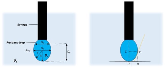
Figure 1.
Schematic illustration of ds/de method for determining the surface tension of polymeric viscous solutions.
= surface tension
∆ = difference in density
g = gravitational acceleration
1/H = correlation factor determined from Ds/De
2.3. Rheological Studies of Polymer Solutions
All rheological measurements were conducted using a Bohlin Gemini Nano HR rheometer (Malvern Instruments, Malvern, UK), equipped with a 55 mm cone and plate geometry. The measurements were performed at varying temperatures (25 °C, 40 °C, 50 °C, and 60 °C) across a range of shear rates, from 0.1 s−1 to 1000 s−1. This setup allowed for a detailed analysis of the flow behaviour and viscosity changes of the polymer solution under different thermal and shear conditions.
2.4. Instrumentation and Experimental Cent-Hydro System
The instrumentation of the bespoke Cent-Hydro system, as developed in our laboratory, is illustrated in Figure 2a. It comprises a rotary aluminium spinning vessel measuring 5.5 cm in diameter and 4 cm in length, equipped with 22 spinneret orifices on its face, each with a diameter of 0.5 mm. The spinning vessel is directly connected to a direct-current motor and a temperature control system. The direct control motor is utilised to rotate the vessel, while a variable-speed motor is employed to set the rotations at different resolutions per minute. The temperature control system is connected to a heating element, capable of adjusting the vessel’s temperature from ambient to 300 °C. Additionally, a temperature-regulated glass syringe (Figure 2b) is installed, capable of controlling the temperature from ambient to 150 °C. Both temperature control systems were tested and validated using an infrared temperature sensing system with an accuracy of ±1 °C. The polymer solution is fed into the spinning vessel via a syringe pump attached to a 25 mL syringe at a constant rate. A stationary collecting net serves as a collector, positioned around the collector to facilitate the convenient collection of nanofibers. During the spinning process, 20 mL of PEO solution at different concentrations is simultaneously fed into the vessel at variable spinning speeds (ranging from 5000 to 60,000 rpm) and temperatures (ranging from 25 to 60 °C), while maintaining a constant working pressure of 0.3 MPa. The distance between the spinning vessel and the collector wall is kept constant at 15 cm throughout the spinning process. Once the nanofibers are collected around the mesh, they are delicately removed and stored in an airtight container placed over a desiccator until further use.
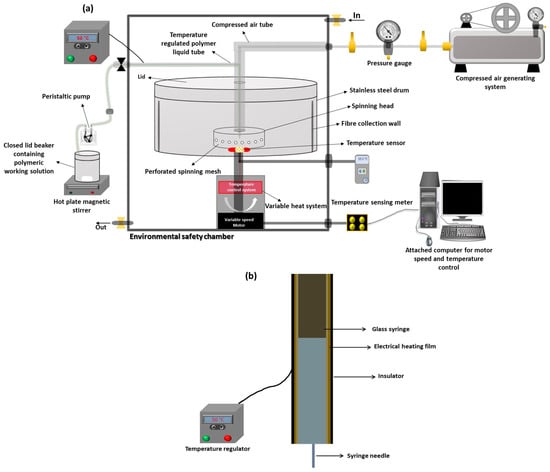
Figure 2.
Schematic illustrations showing (a) the instrumental setup of the Cent-Hydro system and (b) the cross-sectional view of the temperature-regulated glass syringe used in the Cent-Hydro system.
2.5. Characterisation of Nanofibers
The nanofibers developed under varying rotational speeds, polymer content, and working temperatures were gold-coated using a sputter coater (Quorum SC7620 (Quorum Technologies, Laughton, UK) to enhance conductivity for imaging. Surface morphology analysis was performed using a scanning electron microscope (SEM), specifically the Jeol JSM-6060CV model (Jeol Inc., Peabody, MA, USA). For diameter size analysis, all nanofibers were examined using the Keyence VHX digital microscope system (Keyence UK Ltd., Milton Keynes, UK) in conjunction with ImageJ software (version 1.47i). For each PEO nanofiber sample, 100 randomly assigned measurements were taken to ensure accurate and representative diameter data. This methodology provided a comprehensive understanding of the nanofibers’ structural characteristics and size distribution.
2.6. Statistical Analysis
One-way ANOVA (analysis of variance) with a confidence limit of p < 0.05 was used to determine the significance of impact of different factors on nanofiber quality and productivity.
3. Results and Discussion
3.1. Surface Tension and Viscosity of Working PEO Solutions
The surface tension of the polymer solutions versus their concentration at different working temperatures is depicted in Figure 3. It is observable that as the concentration of polymer within the solution increases, the surface tension of the polymer solutions also increases. However, intriguingly, there is a decrease in surface tension with an increase in working temperature from 25 °C to 60 °C. This phenomenon is further elucidated in Figure 4a, where it is evident that the entanglement of polymer chains within the droplet gradually intensifies as the polymer content increases. Consequently, this increased entanglement contributes to the overall increase in surface tension. Conversely, Figure 4b showcases the impact of an increase in working temperature on the surface of the droplet, resulting in a decrease in surface tension. This phenomenon can be attributed to inter-chain relaxation, which creates more space between chains, thereby enhancing their mobility within the solution. As a result, this increased mobility leads to a reduction in surface tension [71].
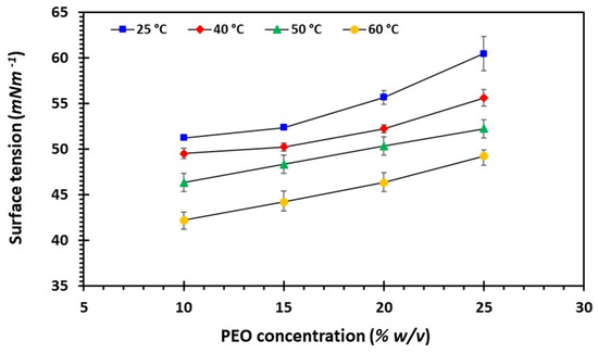
Figure 3.
The surface tension of the polymer solutions versus their concentration at different working temperatures.
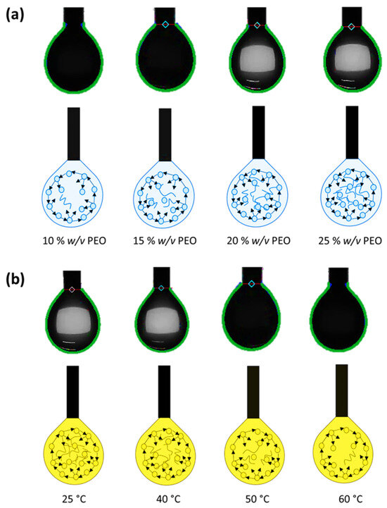
Figure 4.
Schematic illustration depicting the effect of (a) PEO concentration (b) temperature on surface tension of working solutions.
The relationship between solution viscosity, polymer concentration, and working temperature is shown in Figure 5. The rheological profiles of the PEO solutions indicate the viscosity of the solutions decreased with the increase in working temperature from 25 °C to 60 °C. This can be observed from Figure 6; as expected, the solutions with ambient temperature (25 °C) at zero shear rate had higher viscosity compared to the solution with higher temperature due to more relaxation of polymer chains within the solutions, leading to lower viscosity in the PEO solutions. The PEO is a water-soluble polymer known for its unique rheological properties, particularly its shear-thinning behaviour. Shear thinning, or pseudoplasticity, refers to the phenomenon where a material’s viscosity decreases with an increasing shear rate. In the current scenario, as shear stress is applied, the polymer chains, which are typically entangled and form a highly viscous solution at rest, begin to align in the direction of flow, and this alignment starts to reduce the resistance to flow, leading to a drop in viscosity [72]. However, at low shear rates, PEO exhibits a more viscous, elastic behaviour due to the entanglement of long polymer chains. However, as the shear rate increases, these chains become disentangled and orient themselves with the flow, leading to reduced resistance. This behaviour is reversible; when the shear force is removed, the polymer chains return to their original entangled state, and the viscosity increases again. In the Cent-Hydro system, this behaviour is essential as the shear-thinning behaviour of polymers like PEO mitigates the Rayleigh–Taylor instability during nanofiber production, promoting the formation of uniform and continuous fibres. By reducing viscosity under high shear conditions and damping instability growth, shear thinning improves the solution blowing stability under the drag of centrifugal force, fibre diameter control, and overall fibre morphology, which are critical for achieving high-quality nanofibers.
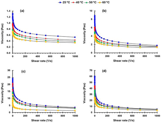
Figure 5.
Rheological profiles of PEO solution of various concentrations (a) 10, (b) 15, (c) 20 and (d) 25% w/v.

Figure 6.
Viscosity of the PEO solutions of various concentrations at zero-shear rate at various working temperatures (25 °C, 40 °C, 50 °C and 60 °C), (a) all the PEO solution and (b) viscosity profile of highlighted area of (a) for visualisation purposes.
3.2. Calibration of Cent-Hydro: Liquid Motion Study
During the spinning process, the polymeric solution is delicately released onto the lid, whereupon it begins to spread rapidly across the surface of the rotating disc. Initially, the liquid forms a thin film that appears almost perfectly flat on the horizontal plane. However, at the line of contact between the liquid and the disc, a subtle ridge begins to emerge. This ridge marks a critical point in the process, where Rayleigh–Taylor instability comes into play. This instability triggers a cascade effect, causing the once-stable ridge to destabilize and fragment into a series of distinct fingers, as distinctly illustrated in Figure 7. As this transformation unfolds, the thickness of the film gradually diminishes with increasing distance from the centre of rotation. Consequently, the surface tension imposed on the ridge proportionally intensifies.

Figure 7.
Time based evolution of 20% w/w PEO aqueous solution on Cent-Hydro system (centrifugal rotation) operating at 0.3 bar (pressure) and 55,000 rpm motor speed, (a) 2 s (b) 4 s and (c) 5 s.
Simultaneously, at the point of contact between the liquid film and the disc, intricate waves emerge, driven by the interplay of surface tension and centrifugal force. This dynamic interaction further accentuates the instability of the ridge, hastening its fragmentation into distinct fingers. Notably, when subjected to high centrifugal forces, the formation of straight fingers becomes more pronounced, indicating a critical point where external force supersedes the inherent surface tension of the liquid film. Thus, it becomes evident that external force and film thickness are paramount in determining the morphology of the resulting fingers during this process, underscoring their pivotal role in shaping the outcome of the spinning process.
The properties of the finger (shape, velocity and number) were affected directly by the jet path. The finger properties were influenced directly by the concentration of the solution and rotational speed. Here, the finger length was denoted by a function of time (t), which was defined as in which the was the velocity of the finger, was the film velocity and t0 was the initial time at which the finger occurred, Figure 8a–d. Here, as an assumption, the finger velocity and film velocity for a short period of time remained constant. To measure finger length and velocity of the film per unit time, the and were considered as an average velocity. Thus, the finger length was simplified into which can be seen in Figure 9a–d, where the increase in rotational speed induces a monotonical rise in polymer jet velocity that leads to faster elongation of finger length, while decreasing the concentration of polymeric solutions favours the formation of longer and thinner fingers (10 and 15% w/v solution). The gradual increase in finger velocity and finger length observed in high solution concentrations (20% and 25% w/v) was due to the strong entanglements of macromolecular chains, which created a hindrance in the development of the polymeric jet. Therefore, the concentration of the solution had the opposite effect on rotational speed for controlling the velocity and length of fingers. The lower polymeric concentration of the solution and higher rotational speed are usually favoured to attain longer and thinner fingers [73].
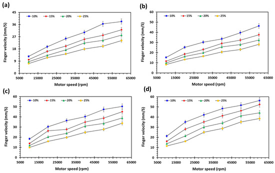
Figure 8.
Finger velocity (Vmax, maximum velocity) of PEO solutions of varying concentrations (10–25% w/v) at different motor rational speed (10,000–60,000 rpm) and temperature (a) 25 °C, (b) 40 °C, (c) 50 °C and (d) 60 °C.
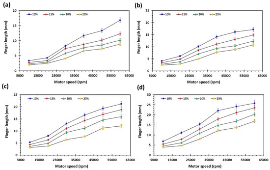
Figure 9.
Finger length (L, ∆t = 1 s) of PEO solutions of varying concentrations (10–25% w/v) at different motor rational speed (10,000–60,000 rpm) and temperature (a) 25 °C, (b) 40 °C, (c) 50 °C and (d) 60 °C.
The effect of an increase in working temperature and rotational speed on the finger velocity and finger length was evaluated. When the temperature of the rotating vessel was kept at 40 °C (Figure 8b and Figure 9b), there was a gradual increase in finger velocity and finger length due to the high viscosity of the solutions, whereas the finger velocity became significantly higher along with larger finger length when the temperature of the rotating vessel was increased to 50 °C under varying rotational speed (Figure 8c and Figure 9c). Similar and more pronounced finger velocity and finger length were seen after a further increase in temperature (60 °C) under the same conditions (Figure 8d and Figure 9d). The fundamental explanation that supports this investigation is that the increase in temperature gives freedom to polymer chain movement, resulting in lower viscosity of the solution [71,74]. Moreover, centrifugal force is applied during the spinning process, which is responsible for the stretching of the polymer jet [75]. The phenomena of stretching are opposed by surface tension and viscous forces (resulting in the creation of new a surface area). Thus, lower solution viscosity at high temperatures will give a higher rate of stretching and a longer polymer jet [68].
During spinning, when the rotational speed was kept low, the droplet did not travel from the orifice due to the balance between capillary force Fγ, centrifugal force FC and viscous force Fµ. Therefore, the polymer jet must achieve critical angular velocity to expel it towards the spiral path [73]. Padron et al. [76] described the balance between capillary force and centrifugal force on the droplet to achieve critical angular velocity. During centrifugal spinning, bumps were formed as the polymeric solution was leaving the lid from the opening side, as shown in Figure 10a. Correspondingly, the balance of centrifugal force , surface tension and viscous force was established. The equation for equilibrium can be expressed as Equation (2);
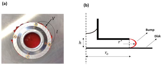
Figure 10.
Polymeric working solution passing through the opening of the lid (a) spinning lid (b) schematic illustration depicted the solution behaviour under the influence of centrifugal force.
Here, is the coefficient of viscosity, is the radius of the lid, is the pressure difference on , is the length and height of the opening, and are the volumes of the bump and curvature of the radius, as represented in Figure 10b. Therefore, the critical angular velocity of the centrifugal spinneret, which was describing the liquid extrusion, could be transcribed as Equation (3).
As the solution of polymer moved onward on the rotating disk, an unbroken film of the polymeric solution was obtained with an increase in rotational speed. As shown in Figure 11a, a ridge was formed at the line of contact at the interface of three phases. A pressure difference was created by the curved ridges that were pointed inwards, which hindered the film development. When the forces act on the ridge of the polymeric film (Figure 11b and Figure 12), the equation can expressed as Equation (4).
where the radius of the minima was , S was the ridge area in the profile, was the viscous force and was the centrifugal force. Thus, polymeric film critical angular velocity can be described as Equation (5).

Figure 11.
Images showing the formation of ridge at the interface of three phases (air, liquid and solid (a) film of liquid (b) fingers.

Figure 12.
Schematic illustration describing the drag force on the ridges.
Therefore, the forces on the tip of the finger lead to Figure 11 and can be expressed as Equation (6):
where the maxima of the radius were denoted as , the finger width was and was the droplet volume. The critical angular velocity further describing the formation of the finger is expressed in Equation (7).
From these findings, three critical angular velocities were applied to the spinneret for the formation of a jet. The first was the critical rotational speed, which formed the film of liquid. The second and third were the critical velocities that pushed the polymeric film and fingers forward.
3.3. Production and Characterisation of Nanofibers
In this study, nanofibers with diverse concentrations of PEO were fabricated by employing a range of temperature (25–60 °C) and motor speed (10,000–60,000 rpm) settings. Subsequently, these nanofibers underwent analysis for diameter and morphology utilising scanning electron microscopy (SEM). In the subsequent section, the results have been thoroughly examined, delving into the impact of various factors such as polymer (PEO) content, temperature variations, and motor speed on the average diameter, size distribution, and morphology of the fabricated nanofibers.
3.3.1. Effect of Motor Speed
PEO nanofibers were fabricated at varying motor speeds ranging from 10,000 to 60,000 rpm. However, certain parameters such as temperature (60 °C), working pressure (0.3 MPa), and PEO concentration (20% w/v) were kept constant to specifically investigate the influence of motor speed on fibre properties. The underlying mechanism of the motor speed’s impact can be attributed to the centrifugal force generated during Cent-Hydro operation. Adequate centrifugal force is crucial to overcome the surface tension of the polymer solution, ensuring that fibres can be effectively produced, Figure 13. An increase in rotational speed amplifies the surface tension, facilitating greater extension and thinning of the polymer jet expelled from the vessel orifices. Consequently, this leads to the production of finer-diameter fibres [77]. SEM images, at low and high magnification (Figure 14) and average fibre diameter measurements (Figure 15), reveal a qualitative shift in fibre morphology from rough and irregular to smoother surfaces as the motor speed increases. The average fibre diameters decrease from 63 nm at 10,000 rpm to 440 nm at 40,000 rpm, attributed to the heightened stretching and thinning of the polymer jet, which accelerates solvent evaporation due to increased surface area [64]. Statistical analysis indicates significant differences (p < 0.5 at 95% confidence interval) in nanofiber size as the rotational speed increases, apart from the comparison between fibres produced at 50,000 and 60,000 rpm. Furthermore, the production yield exhibits an inverse relationship with motor speed, with statistically significant differences observed (p < 0.5 at 95% confidence interval), as depicted in Figure 16.
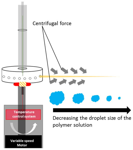
Figure 13.
Schematic illustration showing the impact of centrifugal force on the diameter of nanofiber developed from Cent-Hydro.
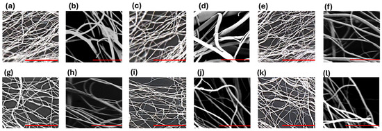
Figure 14.
SEM images of PEO nanofibers developed at different motor speed of Cent-Hydro system; 10,000 rpm (a) low magnification, (b) high magnification, 20,000 rpm (c) low magnification, (d) high magnification, 30,000 rpm (e) low magnification, (f) high magnification, 40,000 rpm (g) low magnification, (h) high magnification, 50,000 rpm (i) low magnification, (j) high magnification and 60,000 rpm (k) low magnification, (l) high magnification. Scale bar (a,c,e,g,i,k) = 50 µm and (b,d,f,h,j,l) = 5 µm.
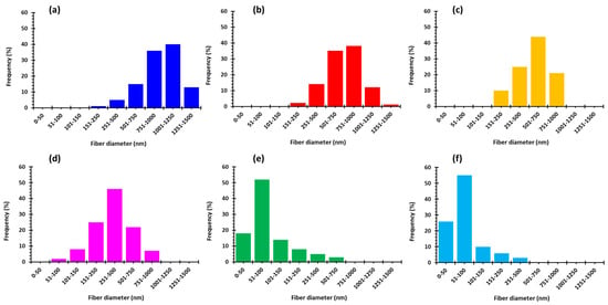
Figure 15.
Fiber diameter distributions developed at different motor speed of Cent-Hydro (a) 10,000, (b) 20,000, (c) 30,000, (d) 40,000, (e) 50,000 and (f) 60,000 rpm.
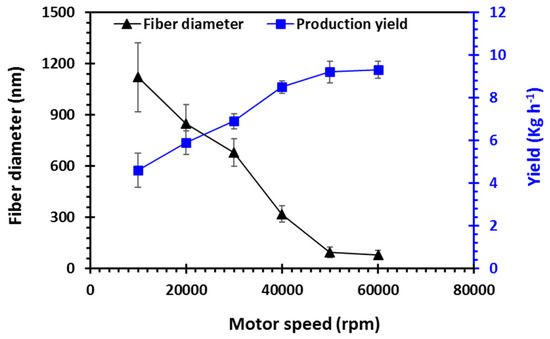
Figure 16.
Nanofiber diameter and production yield with respect to motor speed to Cent-Hydro.
In this study, the optimal motor speed was determined to be 50,000 rpm, beyond which the production of nanofibers was discontinued due to the critical rotational speed limit, resulting in fibre disconnection and bead formation [34].
3.3.2. Effect of PEO Concentration
Nanofibers with varying polymer concentrations (10%, 15%, 20%, and 25% w/v) were fabricated. However, the working pressure (0.3 MPa) and temperature (60 °C) remained constant to evaluate their impact on nanofiber diameter and production yield. Polymer solutions ranging from 10% to 15% concentration facilitated nanofiber fabrication, yet the resulting fibres lacked continuity. This finding corroborates earlier research, indicating the necessity of an optimal polymer concentration to enable adequate polymer chain entanglement for continuous fibre production [78]. SEM images, at low and high magnification (Figure 17), clearly demonstrate that increasing the polymer concentration results in smoother, more uniform, and cylindrical fibres. Fibre morphology is significantly influenced by polymer chain entanglement and molecular weight. Consequently, nanofibers composed of 20% w/v solutions exhibited optimal morphology, appearing relatively smooth and defect-free. The average fibre diameters of PEO nanofibers measured 129.6 nm, 147.4 nm, 178.2 nm, and 187.5 nm corresponding to PEO concentrations of 10%, 15%, 20%, and 25%, respectively, Figure 18. Larger average diameters were positively correlated with polymer solution viscosity, indicating that higher polymer concentration produced fibres with greater diameters [79] and higher production yield (p < 0.5 at 95% confidence interval). However, beyond the 20% w/v concentration, the increase in diameter plateaued, and the effect became statistically insignificant, as illustrated in Figure 19.
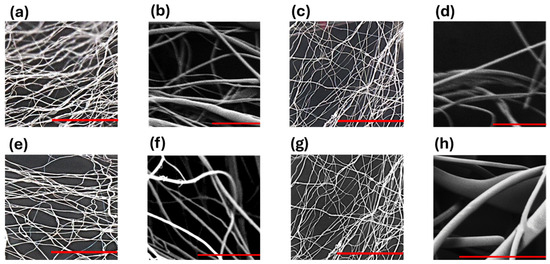
Figure 17.
SEM images of PEO nanofibers developed from different working solutions having different PEO concentration; 10% w/v (a) low magnification, (b) high magnification, 15% w/v (c) low magnification, (d) high magnification, 20% w/v (e) low magnification, (f) high magnification and 25% w/v (g) low magnification, (h) high magnification. Scale bar (a,c,e,g) = 50 µm and (b,d,f,h) = 5 µm.
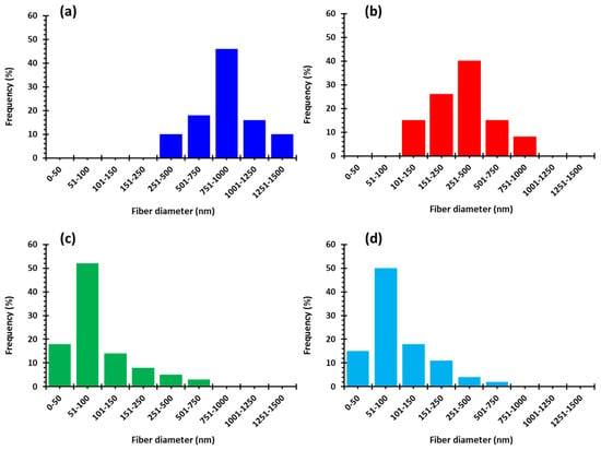
Figure 18.
Fiber diameter distributions developed at different PEO concentration in working solutions (a) 10, (b) 15, (c) 20 and (d) 25% w/v.
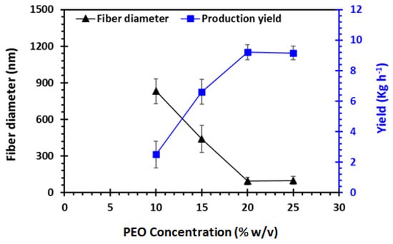
Figure 19.
Nanofiber diameter and production yield with respect to PEO concentration in working solutions.
The size distribution of nanofibers was slightly broader compared to the effect of motor speed, potentially due to the higher viscosity of the polymer solutions, which often exhibit longer stress relaxation times. This characteristic hinders solvent evaporation and opposes jet elongation, thinning, and fracturing [77]. Considering the Cent-Hydro system and the resulting nanofiber morphologies, the optimal PEO concentration in this study was determined to be 20% w/v.
3.3.3. Effect of Temperature
Polyethylene oxide (PEO) nanofibers were precisely fabricated across a range of controlled temperature conditions (25 °C, 40 °C, 50 °C, and 60 °C) using the Cent-Hydro system. To comprehensively investigate the impact of temperature, all other operational parameters—namely, working pressure (0.3 MPa), motor speed (50,000 rpm), and PEO concentration (20% w/v)—were meticulously maintained constantly. The intricate mechanisms underlying the correlation between working temperature, nanofiber diameter, and production rate are clearly illustrated in Figure 20. Furthermore, the scanning electron microscopy (SEM) images at low and high magnification, depicted in Figure 21, provide a visual representation of the nanofibers produced across the working temperature range of 25–60 °C. The results indicated a discernible trend: as the working temperature increased, the average fibre diameter consistently decreased. Figure 22 illustrates the diameter distribution of the fabricated nanofibers, revealing measurements of 530 ± 80 nm, 350 ± 70 nm, and 280 ± 50 nm, respectively.
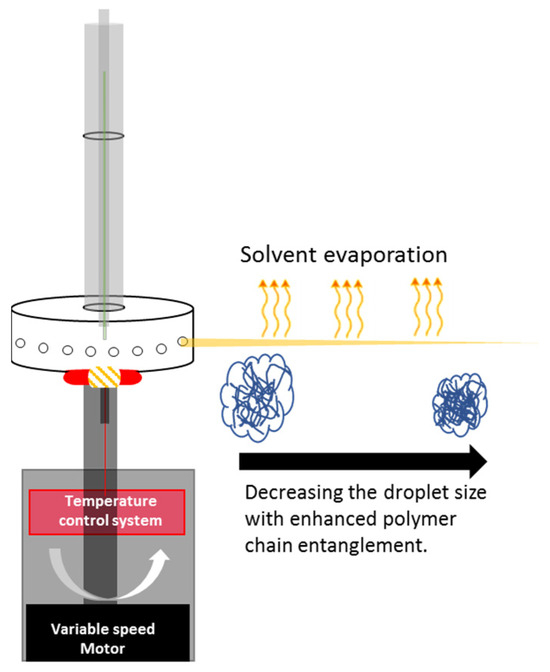
Figure 20.
Schematic illustration showing the impact of working temperature of Cent-Hydro on the diameter of nanofiber developed from Cent-Hydro.
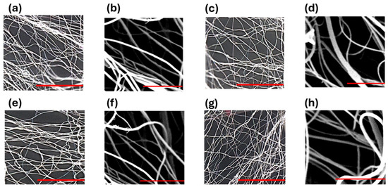
Figure 21.
SEM images of PEO nanofibers developed at different working temperature of Cent-hydro system; 25 °C (a) low magnification, (b) high magnification, 40 °C (c) low magnification, (d) high magnification, 50 °C (e) low magnification, (f) high magnification and 60 °C (g) low magnification, (h) high magnification. Scale bar (a,c,e,g) = 50 µm and (b,d,f,h) = 5 µm.
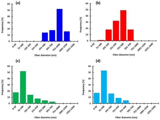
Figure 22.
Fiber diameter distributions developed at different working temperature of Cent-hydro system; (a) 25 °C, (b) 40 °C, (c) 50 °C and (d) 60 °C.
Interestingly, the statistical analysis showed no significant difference between the fibre diameters recorded at 50 °C and 60 °C, both yielding nanofibers with an average diameter of ~260 nm. This finding suggests that further increases in temperature did not significantly affect the development of nanofibers, reinforcing the inverse relationship between working temperature and average fibre diameter. Specifically, higher working temperatures were associated with a reduction in nanofiber diameter. These differences were statistically significant, with p-values < 0.05 at a 95% confidence interval. Moreover, a notable direct correlation was observed between the production yield and the working temperature of the Cent-Hydro system (Figure 23), a relationship that was statistically significant (p < 0.05 at a 95% confidence interval).

Figure 23.
Nanofiber diameter and production yield with respect to working temperature of Cent-Hydro system.
The observed trends of finer nanofiber diameters and higher production yield at higher temperatures can be explained by several thermally induced effects on the polymer solution. Elevated temperatures reduce the solution’s viscosity, making the polymer chains more mobile and easier to stretch into finer fibres. Additionally, the surface tension decreases, allowing the polymer jet to elongate more smoothly, leading to the formation of smaller, defect-free fibres. Increased temperatures also accelerate solvent evaporation, concentrating the polymer and enhancing chain entanglement, which stabilises the nanofiber structure and prevents breakage [80]. These combined effects—lower viscosity, reduced surface tension, faster solvent evaporation, and enhanced polymer entanglement—optimise the fibre formation process, resulting in smaller diameter nanofibers with improved morphological characteristics and higher production yield, making temperature a crucial factor in nanofiber production.
In conclusion, the findings of this study demonstrate that increasing the working temperature does not hinder the spinnability of PEO solutions within the Cent-Hydro system. Moreover, higher temperatures promote the production of nanofibers with smoother surface morphologies and fewer surface indentations [67]. These insights contribute to a better understanding of the relationship between operational temperature and nanofiber fabrication, providing a foundation for optimising the production of nanofibers for various applications.
3.4. Comparison with Other Published Techniques
The production yield and diameter of developed nanofibers were compared with other published techniques (Table 1). It is evident that the Cent-Hydro has a higher productivity than all the techniques with an average diameter of 95 ± 30, which is comparable to centrifugal spinning, electrospinning, and pressurised gyration techniques. It is expected from these results that Cent-Hydro has the potential to develop nanofibers with great versatility. Given these promising results, it is anticipated that the Cent-Hydro system possesses the versatility to develop nanofibers suitable for a wide range of applications. As research progresses, this system is expected to play a pivotal role in advancing nanofiber fabrication processes and may, in the future, be widely implemented across various industrial sectors, including drug delivery, filtration, biomedical devices, tissue engineering, and energy storage. The Cent-Hydro system’s combination of high productivity and precise fibre control positions it as a promising technology for large-scale nanofiber manufacturing.

Table 1.
Comparison of Cent-Hydro system with various other nanofiber manufacturing techniques.
4. Conclusions
Polymeric nanofibers were successfully developed using a hybrid Cent-Hydro system. The increase in working temperature led to a reduction in the viscosity and surface tension of the polymeric solution. Through the calibration of the Cent-Hydro system, it was observed that the polymer solution spread in the form of thin fingers on the rotating disk due to Rayleigh–Taylor instability. Notably, the system generated thinner and longer fingers when lower polymeric solutions were added at high rotational speeds. The effects of increased rotational speed and working temperature significantly elevated finger velocity and finger length. Moreover, these enhancements resulted in a reduction in fibre diameter and higher production yield. Interestingly, an increase in polymer content beyond 20% did not yield any significant difference in fibre morphology. The nanofibers produced from this innovative system exhibited smooth morphological characteristics. This system facilitates the fabrication of well-aligned nanofibers on a large scale, offering variable rotational speed and working temperature settings. Furthermore, comparative analyses of functionality have underscored the potential of the Cent-Hydro system. It is anticipated that in the future, this system will find widespread implementation across various industrial applications.
Author Contributions
Conceptualization, M.U.G. and B.R.C.; methodology, S.F., N.A., A.M.S., B.R.C. and M.U.G.; formal analysis, S.F. and M.U.G.; Investigation, S.F., N.A., A.M.S., B.R.C. and M.U.G.; data curation, S.F. and N.A.; writing—original draft preparation, S.F.; writing—review and editing, S.F., B.R.C. and M.U.G.; supervision, B.R.C. and M.U.G.; project administration, M.U.G. All authors have read and agreed to the published version of the manuscript.
Funding
This research received no external funding.
Institutional Review Board Statement
Not applicable.
Data Availability Statement
All the data are available in the manuscript.
Acknowledgments
The authors extend their gratitude to Therm-o-Rad UK Limited for their generous provision of engineering and technical support during the manufacturing process of the Cent-Hydro system. Additionally, Samia Farhaj expresses thanks to the University of Huddersfield for awarding her a Fee-Waiver Scholarship to support her doctoral studies.
Conflicts of Interest
The authors declare no conflicts of interest.
References
- Barhoum, A.; Pal, K.; Rahier, H.; Uludag, H.; Kim, I.S.; Bechelany, M. Nanofibers as new-generation materials: From spinning and nano-spinning fabrication techniques to emerging applications. Appl. Mater. Today 2019, 17, 1–35. [Google Scholar] [CrossRef]
- Dabirian, F.; Ravandi, S.H.; Pishevar, A.; Abuzade, R.A. A comparative study of jet formation and nanofiber alignment in electrospinning and electrocentrifugal spinning systems. J. Electrost. 2011, 69, 540–546. [Google Scholar] [CrossRef]
- Li, H.M.; Zhang, Q.G.; Guo, N.N.; Zhu, A.M.; Liu, Q.L. Ultrafine polystyrene nanofibers and its application in nanofibrous membranes. Chem. Eng. J. 2015, 264, 329–335. [Google Scholar] [CrossRef]
- Khan, I.; Pandit, J.; Ahmed, S.; Zameer, S.; Nikita; Ahmad, S.; Bano, S.; Ansari, M.D.; Solanki, P.; Jahan, R.N.; et al. Development and evaluation of biodegradable polymeric lomustine nanofibres for the efficient tumor targeting: In vitro characterization, ex vivo permeation and degradation study. J. Drug Deliv. Sci. Technol. 2022, 75, 103685. [Google Scholar] [CrossRef]
- Farhaj, S.; Conway, B.R.; Ghori, M.U. Nanofibres in drug delivery applications. Fibers 2023, 11, 21. [Google Scholar] [CrossRef]
- Yousaf, A.; Shahzad, Y.; Din, F.U.; Yousaf, Q.U.A.; Hussain, T.; Ghori, M.U.; Rizvi, S. Polymeric Nanofibers for Wound Dressing Applications. In Nanotherapeutic Strategies and New Pharmaceuticals (Part 2); Khan, S.A., Salman, S., Al-Ghamdi, Y.O., Eds.; Bentham Science Publishers B.V.: Sharjah, United Arab Emirates, 2021; pp. 113–141. [Google Scholar]
- Hameed, M.; Rasul, A.; Nazir, A.; Yousaf, A.; Hussain, T.; Khan, I.U.; Abbas, G.; Asif, S.; Yousaf, Q.U.A.; Ghori, M.U.; et al. Moxifloxacin-loaded electrospun polymeric composite nanofibers-based wound dressing for enhanced antibacterial activity and healing efficacy. Int. J. Polym. Mater. 2021, 70, 1271–1279. [Google Scholar] [CrossRef]
- Sill, T.J.; Von Recum, H.A. Electrospinning: Applications in drug delivery and tissue engineering. Biomaterials 2008, 29, 1989–2006. [Google Scholar] [CrossRef]
- Uyar, T.; Kny, E. Electrospun Materials for Tissue Engineering and Biomedical Applications: Research, Design and Commercialization; Woodhead Publishing Series in Biomaterials; Woodhead Publishing: Cambridge, UK, 2017; pp. 57–91. [Google Scholar]
- Yu, D.G.; Shen, X.X.; Branford-White, C.; White, K.; Zhu, L.M.; Bligh, S.A. Oral fast-dissolving drug delivery membranes prepared from electrospun polyvinylpyrrolidone ultrafine fibers. Nanotechnology 2009, 20, 055104. [Google Scholar] [CrossRef]
- Bajakova, J.; Chaloupek, J.; Lukáš, D.; Lacarin, M. Drawing–The production of individual nanofibers by experimental method. In Proceedings of the 3rd International Conference on Nanotechnology-Smart Materials (NANOCON’11), Brno, Czech Republic, 21–23 September 2011; SPIE: Bellingham, WA, USA, 2011. [Google Scholar]
- Liang, H.W.; Guan, Q.-F.; Chen, L.F.; Zhu, Z.; Zhang, W.J.; Yu, S.H. Macroscopic-Scale Template Synthesis of Robust Carbonaceous Nanofiber Hydrogels and Aerogels and Their Applications. Angew. Chem. Int. Ed. 2012, 51, 5101–5105. [Google Scholar] [CrossRef]
- Zhang, X.; Lu, Y. Centrifugal spinning: An alternative approach to fabricate nanofibers at high speed and low cost. Polym. Rev. 2014, 54, 677–701. [Google Scholar] [CrossRef]
- Yan, G.; Yu, J.; Qiu, Y.; Yi, X.; Lu, J.; Zhou, X.; Bai, X. Self-Assembly of Electrospun Polymer Nanofibers: A General Phenomenon Generating Honeycomb-Patterned Nanofibrous Structures. Langmuir 2011, 27, 4285–4289. [Google Scholar] [CrossRef] [PubMed]
- Ellison, C.J.; Phatak, A.; Giles, D.W.; Macosko, C.W.; Bates, F.S. Melt blown nanofibers: Fiber diameter distributions and onset of fiber breakup. Polymer 2007, 48, 3306–3316. [Google Scholar] [CrossRef]
- Subbiah, T.; Bhat, G.S.; Tock, R.W.; Parameswaran, S.; Ramkumar, S.S. Electrospinning of nanofibers. J. Appl. Polym. Sci. 2005, 96, 557–569. [Google Scholar] [CrossRef]
- Madurantakam, P.A.; Rodriguez, I.A.; Cost, C.P.; Viswanathan, R.; Simpson, D.G.; Beckman, M.J.; Moon, P.C.; Bowlin, G.L. Multiple factor interactions in biomimetic mineralization of electrospun scaffolds. Biomaterials 2009, 30, 5456–5464. [Google Scholar] [CrossRef] [PubMed]
- Padron, S. 2D Modeling of Forcespinning™ Nanofiber Formation with Experimental Study and Validation. Master’s Thesis, The University of Texas-Pan American, Edinburg, TX, USA, August 2012. [Google Scholar]
- Zhou, F.L.; Gong, R.H. Manufacturing technologies of polymeric nanofibres and nanofibre yarns. Polym. Int. 2008, 57, 837–845. [Google Scholar] [CrossRef]
- Nayak, R.; Padhye, R.; Kyratzis, I.L.; Truong, Y.B.; Arnold, L. Recent advances in nanofibre fabrication techniques. Text. Res. J. 2011, 82, 129–147. [Google Scholar] [CrossRef]
- Medeiros, E.S.; Glenn, G.M.; Klamczynski, A.P.; Orts, W.J.; Mattoso, L.H.C. Solution blow spinning: A new method to produce micro- and nanofibers from polymer solutions. J. Appl. Polym. Sci. 2009, 113, 2322–2330. [Google Scholar] [CrossRef]
- Cheng, F.; Tang, W.; Li, C.; Chen, J.; Liu, H.; Shen, P.; Dou, S. Conducting Poly(aniline) Nanotubes and Nanofibers: Controlled Synthesis and Application in Lithium/Poly(aniline) Rechargeable Batteries. Chem. Eur. J. 2006, 12, 3082–3088. [Google Scholar] [CrossRef]
- Tsuboi, Y.; Yoshida, Y.; Okada, K.; Kitamura, N. Phase Separation Dynamics of Aqueous Solutions of Thermoresponsive Polymers Studied by a Laser T-Jump Technique. J. Phys. Chem. B 2008, 112, 2562–2565. [Google Scholar] [CrossRef]
- Yan, X.; Liu, G.; Liu, F.; Tang, B.Z.; Peng, H.; Pakhomov, A.B.; Wong, C.Y. Superparamagnetic Triblock Copolymer/Fe2O3 Hybrid Nanofibers. Angew. Chem. 2001, 113, 3705–3708. [Google Scholar] [CrossRef]
- Endres, T.; Zheng, M.; Beck-Broichsitter, M.; Samsonova, O.; Debus, H.; Kissel, T. Optimising the self-assembly of siRNA loaded PEG-PCL-lPEI nano-carriers employing different preparation techniques. J. Control. Release 2012, 160, 583–591. [Google Scholar] [CrossRef] [PubMed]
- Grafe, T.; Graham, K. Polymeric nanofibers and nanofiber webs: A new class of nonwovens. Int. Nonwovens J. 2003, 12, 51–55. [Google Scholar] [CrossRef]
- Sundaray, B.; Subramanian, V.; Natarajan, T.; Xiang, R.Z.; Chang, C.C.; Fann, W.S. Electrospinning of continuous aligned polymer fibers. Appl. Phys. Lett. 2004, 84, 1222–1224. [Google Scholar] [CrossRef]
- Megelski, S.; Stephens, J.S.; Chase, D.B.; Rabolt, J.F. Micro- and Nanostructured Surface Morphology on Electrospun Polymer Fibers. Macromolecules 2002, 35, 8456–8466. [Google Scholar] [CrossRef]
- Baji, A.; Mai, Y.-W.; Wong, S.-C.; Abtahi, M.; Chen, P. Electrospinning of polymer nanofibers: Effects on oriented morphology, structures and tensile properties. Compos. Sci. Technol. 2010, 70, 703–718. [Google Scholar] [CrossRef]
- Nair, S.; Kim, J.; Crawford, B.; Kim, S.H. Improving Biocatalytic Activity of Enzyme-Loaded Nanofibers by Dispersing Entangled Nanofiber Structure. Biomacromolecules 2007, 8, 1266–1270. [Google Scholar] [CrossRef]
- Sarkar, K.; Gomez, C.; Zambrano, S.; Ramirez, M.; de Hoyos, E.; Vasquez, H.; Lozano, K. Electrospinning to Forcespinning™. Mater. Today 2010, 13, 12–14. [Google Scholar] [CrossRef]
- Badrossamay, M.R.; McIlwee, H.A.; Goss, J.A.; Parker, K.K. Nanofiber assembly by rotary jet-spinning. Nano Lett. 2010, 10, 2257–2261. [Google Scholar] [CrossRef]
- Haider, A.; Haider, S.; Kummara, M.R.; Kamal, T.; Alghyamah, A.A.A.; Iftikhar, F.J.; Bano, B.; Khan, N.; Afridi, M.A.; Han, S.S. Advances in the scaffolds fabrication techniques using biocompatible polymers and their biomedical application: A technical and statistical review. J. Saudi Chem. Soc. 2020, 24, 186–215. [Google Scholar] [CrossRef]
- Zhang, Z.-M.; Duan, Y.-S.; Xu, Q.; Zhang, B. A review on nanofiber fabrication with the effect of high-speed centrifugal force field. J. Eng. Fibers Fabr. 2019, 14, 14. [Google Scholar] [CrossRef]
- Yanilmaz, M.; Zhang, X. Polymethylmethacrylate/polyacrylonitrile membranes via centrifugal spinning as separator in Li-ion batteries. Polymers 2015, 7, 629–643. [Google Scholar] [CrossRef]
- McEachin, Z.; Lozano, K. Production and characterization of polycaprolactone nanofibers via forcespinning™ technology. J. Appl. Polym. Sci. 2012, 126, 473–479. [Google Scholar] [CrossRef]
- Zander, N.E. Formation of melt and solution spun polycaprolactone fibers by centrifugal spinning. J. Appl. Polym. Sci. 2015, 132, 132. [Google Scholar] [CrossRef]
- Zhang, X. Fundamentals of Fiber Science; DEStech Publications, Inc.: Lancaster, PA, USA, 2014; pp. 233–236. [Google Scholar]
- Stojanovska, E.; Canbay, E.; Pampal, E.S.; Calisir, M.D.; Agma, O.; Polat, Y.; Simsek, R.; Gundogdu, N.S.; Akgul, Y.; Kilic, A. A review on non-electro nanofibre spinning techniques. RSC Adv. 2016, 6, 83783–83801. [Google Scholar] [CrossRef]
- Taghavi, S.M.; Larson, R.G. Regularized thin-fiber model for nanofiber formation by centrifugal spinning. Phys. Rev. E 2014, 89, 023011. [Google Scholar] [CrossRef] [PubMed]
- Mellado, P.; McIlwee, H.A.; Badrossamay, M.R.; Goss, J.A.; Mahadevan, L.; Parker, K.K. A simple model for nanofiber formation by rotary jet-spinning. Appl. Phys. Lett. 2011, 99, 203107. [Google Scholar] [CrossRef]
- Peng, H.; Liu, Y.; Ramakrishna, S. Recent development of centrifugal electrospinning. J. Appl. Polym. Sci. 2017, 134. [Google Scholar] [CrossRef]
- Merchiers, J.; Meurs, W.; Deferme, W.; Peeters, R.; Buntinx, M.; Reddy, N.K. Influence of Polymer Concentration and Nozzle Material on Centrifugal Fiber Spinning. Polymers 2020, 12, 575. [Google Scholar] [CrossRef]
- Zhang, L.; Kopperstad, P.; West, M.; Hedin, N.; Fong, H. Generation of polymer ultrafine fibers through solution (air-) blowing. J. Appl. Polym. Sci. 2009, 114, 3479–3486. [Google Scholar] [CrossRef]
- Shi, S.; Zhuang, X.; Cheng, B.; Wang, X. Solution blowing of ZnO nanoflake-encapsulated carbon nanofibers as electrodes for supercapacitors. J. Mater. Chem. A 2013, 1, 13779–13788. [Google Scholar] [CrossRef]
- Zheng, W.; Wang, X. Effects of cylindrical-electrode-assisted solution blowing spinning process parameters on polymer nanofiber morphology and microstructure. e-Polymers 2019, 19, 190–202. [Google Scholar] [CrossRef]
- Tabakoglu, S.; Kołbuk, D.; Sajkiewicz, P. Multifluid electrospinning for multi-drug delivery systems: Pros and cons, challenges, and future directions. Biomater. Sci. 2023, 11, 37–61. [Google Scholar] [CrossRef] [PubMed]
- Malara, A. Environmental concerns on the use of the electrospinning technique for the production of polymeric micro/nanofibers. Sci. Rep. 2024, 14, 8293. [Google Scholar] [CrossRef] [PubMed]
- Kumar, T.S.M.; Kumar, K.S.; Rajini, N.; Siengchin, S.; Ayrilmis, N.; Rajulu, A.V. A comprehensive review of electrospun nanofibers: Food and packaging perspective. Compos. Part B Eng. 2019, 175, 107074. [Google Scholar] [CrossRef]
- Al-Abduljabbar, A.; Farooq, I. Electrospun polymer nanofibers: Processing, properties, and applications. Polymers 2022, 15, 65. [Google Scholar] [CrossRef]
- Nagy, Z.K.; Balogh, A.; Démuth, B.; Pataki, H.; Vigh, T.; Szabó, B.; Molnár, K.; Schmidt, B.T.; Horák, P.; Marosi, G.; et al. High speed electrospinning for scaled-up production of amorphous solid dispersion of itraconazole. Int. J. Pharma 2015, 480, 137–142. [Google Scholar] [CrossRef]
- Vass, P.; Démuth, B.; Farkas, A.; Hirsch, E.; Szabó, E.; Nagy, B.; Andersen, S.K.; Vigh, T.; Verreck, G.; Csontos, I.; et al. Continuous alternative to freeze drying: Manufacturing of cyclodextrin-based reconstitution powder from aqueous solution using scaled-up electrospinning. J. Control. Release 2019, 298, 120–127. [Google Scholar] [CrossRef]
- Kiss, K.; Vass, P.; Farkas, A.; Hirsch, E.; Szabó, E.; Mező, G.; Nagy, Z.K.; Marosi, G. A solid doxycycline HP-β-CD formulation for reconstitution (iv bolus) prepared by scaled-up electrospinning. Int. J. Pharm. 2020, 586, 119539. [Google Scholar] [CrossRef]
- Madheswaran, D.; Sivan, M.; Hauzerova, S.; Kostakova, E.K.; Jencova, V.; Valtera, J.; Behalek, L.; Mullerova, J.; Nguyen, N.H.; Capek, L.; et al. Continuous fabrication of braided composite nanofibrous surgical yarns using advanced AC electrospinning and braiding technology. Compos. Commun. 2024, 48, 101932. [Google Scholar] [CrossRef]
- Elmarco Nanospider™. Available online: https://www.elmarco.com/nanospider (accessed on 30 September 2024).
- Bioinicia Fluidnatek® LE Series. Available online: https://bioinicia.com/electrospinning-electrospraying-lab-equipment/ (accessed on 30 September 2024).
- Inovenso Industrial Electrospinning Line. Available online: https://www.inovenso.com/product/?gad_source=1&gclid=CjwKCAjwgfm3BhBeEiwAFfxrG8xubk4qrdpgxiM3ubYeRCNDrJe_bQAcMJ3PdvSuFJPpIiGT-GwsrRoC5egQAvD_BwE (accessed on 30 September 2024).
- NANON, SpinTech Systems, ElectrospinTech Machines. Available online: https://www.mecc-nano.com/equipment11/ (accessed on 30 September 2024).
- MECC Co., Ltd.—NF Series. Available online: https://www.mecc-nano.com/ (accessed on 30 September 2024).
- Ahmed, F.E.; Lalia, B.S.; Hashaikeh, R. A review on electrospinning for membrane fabrication: Challenges and applications. Desalination 2015, 356, 15–30. [Google Scholar] [CrossRef]
- Nascimento, M.L.F.; Araujo, E.S.; Cordeiro, E.R.; de Oliveira, A.H.P.; de Oliveira, H.P. A literature investigation about electrospinning and nanofibers: Historical trends, current status and future challenges. Recent Pat. Nanotechnol. 2015, 9, 76–85. [Google Scholar] [CrossRef] [PubMed]
- Li, Y.; Zhu, J.; Cheng, H.; Li, G.; Cho, H.; Jiang, M.; Gao, Q.; Zhang, X. Developments of advanced electrospinning techniques: A critical review. Adv. Mater. Technol. 2021, 6, 2100410. [Google Scholar] [CrossRef]
- Mahalingam, S.; Edirisinghe, M. Forming of polymer nanofibers by a pressurised gyration process. Macromol. Rapid Commun. 2013, 34, 1134–1139. [Google Scholar] [CrossRef] [PubMed]
- Heseltine, P.L.; Ahmed, J.; Edirisinghe, M. Developments in Pressurized Gyration for the Mass Production of Polymeric Fibers. Macromol. Mater. Eng. 2018, 303, 1800218. [Google Scholar] [CrossRef]
- Raimi-Abraham, B.T.; Mahalingam, S.; Edirisinghe, M.; Craig, D.Q. Generation of poly (N-vinylpyrrolidone) nanofibres using pressurised gyration. Mater. Sci. Eng. C 2014, 39, 168–176. [Google Scholar] [CrossRef]
- Raimi-Abraham, B.T.; Mahalingam, S.; Davies, P.J.; Edirisinghe, M.; Craig, D.Q. Development and characterization of amorphous nanofiber drug dispersions prepared using pressurized gyration. Mol. Pharm. 2015, 12, 3851–3861. [Google Scholar] [CrossRef]
- Yang, G.Z.; Li, H.P.; Yang, J.H.; Wan, J.; Yu, D.G. Influence of Working Temperature on The Formation of Electrospun Polymer Nanofibers. Nanoscale Res. Lett. 2017, 12, 55. [Google Scholar] [CrossRef]
- De Vrieze, S.; Van Camp, T.; Nelvig, A.; Hagström, B.; Westbroek, P.; De Clerck, K. The effect of temperature and humidity on electrospinning. J. Mater. Sci. 2009, 44, 1357–1362. [Google Scholar] [CrossRef]
- Hardick, O.; Stevens, B.; Bracewell, D.G. Nanofibre fabrication in a temperature and humidity controlled environment for improved fibre consistency. J. Mater. Sci. 2011, 46, 3890–3898. [Google Scholar] [CrossRef]
- Putti, M.; Simonet, M.; Solberg, R.; Peters, G.W.M. Electrospinning poly(ε-caprolactone) under controlled environmental conditions: Influence on fiber morphology and orientation. Polymer 2015, 63, 189–195. [Google Scholar] [CrossRef]
- Bhattacharya, A.; Ray, P. Studies on surface tension of poly(vinyl alcohol): Effect of concentration, temperature, and addition of chaotropic agents. J. Appl. Polym. Sci. 2004, 93, 122–130. [Google Scholar] [CrossRef]
- Al-Shammari, B.; Al-Fariss, T.; Al-Sewailm, F.; Elleithy, R. The effect of polymer concentration and temperature on the rheological behavior of metallocene linear low density polyethylene (mLLDPE) solutions. J. King Saud Univ. Eng. Sci. 2011, 23, 9–14. [Google Scholar] [CrossRef]
- Wang, C.; Chien, H.S.; Hsu, C.H.; Wang, Y.C.; Wang, C.T.; Lu, H.A. Electrospinning of polyacrylonitrile solutions at elevated temperatures. Macromolecules 2007, 40, 7973–7983. [Google Scholar] [CrossRef]
- Xu, H.; Chen, H.; Li, X.; Liu, C.; Yang, B. A comparative study of jet formation in nozzle-and nozzle-less centrifugal spinning systems. J. Polym. Sci. Part B Polym. Phys. 2014, 52, 1547–1559. [Google Scholar] [CrossRef]
- Weng, B.; Xu, F.; Alcoutlabi, M.; Mao, Y.; Lozano, K. Fibrous cellulose membrane mass produced via forcespinning® for lithium-ion battery separators. Cellulose 2015, 22, 1311–1320. [Google Scholar] [CrossRef]
- Padron, S.; Fuentes, A.; Caruntu, D.; Lozano, K. Experimental study of nanofiber production through forcespinning. J. Appl. Phys. 2013, 113, 024318. [Google Scholar] [CrossRef]
- Lu, Y.; Li, Y.; Zhang, S.; Xu, G.; Fu, K.; Lee, H.; Zhang, X. Parameter study and characterization for polyacrylonitrile nanofibers fabricated via centrifugal spinning process. Eur. Polym. J. 2013, 49, 3834–3845. [Google Scholar] [CrossRef]
- Schneider, H.; Steuber, J.; Du, W.; Mortazavi, M.; Bullock, D. Polyethylene oxide nanofiber production by electrospinning. J. Ark. Acad. Sci. 2016, 70, 211–215. [Google Scholar] [CrossRef]
- Beachley, V.; Wen, X. Effect of electrospinning parameters on the nanofiber diameter and length. Mater. Sci. Eng. C 2009, 29, 663–668. [Google Scholar] [CrossRef]
- Haider, A.; Haider, S.; Kang, I.-K. A comprehensive review summarizing the effect of electrospinning parameters and potential applications of nanofibers in biomedical and biotechnology. Arab. J. Chem. 2018, 11, 1165–1188. [Google Scholar] [CrossRef]
Disclaimer/Publisher’s Note: The statements, opinions and data contained in all publications are solely those of the individual author(s) and contributor(s) and not of MDPI and/or the editor(s). MDPI and/or the editor(s) disclaim responsibility for any injury to people or property resulting from any ideas, methods, instructions or products referred to in the content. |
© 2024 by the authors. Licensee MDPI, Basel, Switzerland. This article is an open access article distributed under the terms and conditions of the Creative Commons Attribution (CC BY) license (https://creativecommons.org/licenses/by/4.0/).