Article

Development of Knitted Compression Covers for Amputated Limbs

by
Daiva Mikucioniene
1,
Liudmyla Halavska
2,
Ginta Laureckiene
1,
Liudmyla Melnyk
2,
Svitlana Arabuli
2 and
Rimvydas Milašius
1,*
1
Faculty of Mechanical Engineering and Design, Kaunas University of Technology, Studentu Str. 56, LT51424 Kaunas, Lithuania
2
Faculty of Arts and Fashion, Kyiv National University of Technologies and Design, Mala Shyianovska Str. 2, 01011 Kyiv, Ukraine
*
Author to whom correspondence should be addressed.
Fibers 2024, 12(10), 80; https://doi.org/10.3390/fib12100080
Submission received: 22 July 2024 / Revised: 28 August 2024 / Accepted: 23 September 2024 / Published: 27 September 2024

Abstract

:
Compression therapy can be successfully applied to the treatment of amputated limbs. Compression is known to speed healing and reduce the appearance of complex scars. This is particularly relevant as the number of amputations increases, especially during times of war, such as the current war in Ukraine. For the research presented in this article, compression knits of two pattern repeats and twelve structural variations each were created. We investigated how the compression generated by the knit is influenced by the main factors which theoretically could have an effect: knitting pattern, density of loops, speed of the wheel supplying elastomeric inlay-yarn into the knitting zone, and elongation resulting from the difference between the knitted limb cover and limb circumference. It was found that in the area of low elongations (up to 50%) of the investigated elastomeric knits, the speed of supply of the inlay-yarn does not have a significant influence on the compression. However, the effect of loop density and knitting elongation on the generated compression is significant and manifests linearly. In addition, the established equations can be used for compression prediction and knitting design according to the required compression class.

1. Introduction

The concept of medical textiles is very broad, including textile products with various purposes and different levels of complexity and structure [1,2,3,4]. A large part of medical textile products consists of products intended for compression therapy. This group includes compression stockings for the prevention and treatment of varicose veins, orthopedic compression supports or bandages for the treatment and prevention of joint injuries and diseases, compression covers for the treatment of wounds and scars, etc. [1,5,6]. Compression pressure is defined as the normal force that acts on the surface area of a body. This force appears due to the difference in the circumferences of the compression product and the body, i.e., due to the fact that the compression product is worn in a stretched state [5,7,8].
One of the fields where compression therapy can successfully be applied is the treatment of amputated limbs. There is a wide range of reasons for limb amputation, like traffic accidents, industrial and home injuries, gunshot injuries, burns, diabetes, etc. During war, common injuries are gunshot wounds, which often result in limb amputations when amputation is the only way to save patients’ lives and prevent further development of disease. Since 2014, the war in Ukraine has touched almost every family and has caused an increase in the number of people with amputated limbs regardless of the field of employment: soldiers or medics, rescuers or volunteers, teachers, farmers, etc. It has been established that the causes of traumatic limb amputation in this context are as follows: 78.4%—mine-explosive injuries, 11.7%—explosive wounds, 5.9%—gunshot wounds. Almost 84.3% of military personnel have lost one, 13.7% lost two, and 2% lost three limbs. According to the data of the Military Medical Clinical Center of the Western Region for the period of February–September, 2022, 63.3% of wounded soldiers suffered a combat limb injury, and among them, 17.8% were injured by firearms, 10.4% by shrapnel, and 68.1% by mine-explosion, while 5.8% of the victims were treated for amputated stumps [9]. In contrast to the non-traumatic type of amputations, the age of injured military personnel varies from 19 to 60 years. The frequency of amputation of different segments of the upper limb is as follows: 29.0%—shoulder segment, 40.3%—elbow segment, and 30.6%—hand. The frequency of amputation of the femoral (42.6%) and tibial (41.1%) segments of the lower limb is higher than that of the foot (16.3%) [9,10]. These statistical data should be taken into account when determining the need for prosthetics of limbs. Pre-prosthetic rehabilitation involves compression therapy, scar massage, stump hygiene, and phantom pain management. Swelling is a big problem during this period. Compression therapy is the method for its prevention. At the same time, the purpose of this therapy is to correct stump formation (keloids and hypertrophic scar formation [11]), to repair the scars, and to reduce phantom pain. When constant compression, higher than the pressure of capillary vessels, is applied to the treatment of amputated limbs, it affects the formation of keloids and significantly prevents their hypertrophy. Scars heal faster and more evenly. Prolonged pressure slows down metabolism and decreases the number of fibroblasts [12]. A variety of compression covers for amputated limbs are described in detail in [1].
Covers for amputated limbs are usually produced by using circular weft-knitting technology. Innovative textile technologies and product design provide a wide range of opportunities to improve, optimize, and individualize compression therapy [7,13]. One of the essential elements of compression therapy is the selection of the required knitted structure and its technological and physical–mechanical parameters, such as the loop length, loop density, and principle of laying of elastomeric yarns, which ensure the application of the desired value of compression for the treatment of amputated limbs. Knitted compression products are produced by using at least two different systems of yarns: ground yarns, which ensure the thickness and stiffness of the product, and highly stretchable inlay-yarns [1,14,15]. Elastomeric yarns with high stretch are inserted into the product structure to create the required level of pressure on the body [1,5]. These yarns can be inserted into the knitted structure as a plated yarn or as an inlay-yarn. If the elastomeric yarn is used as the plated yarn, it creates conventional loops, and such a knitted structure can be used for light-compression therapy. If the elastomeric yarn is used as the inlay-yarn, it in turn creates floats and tucks or is laid relatively straight; a knitted structure with elastomeric inlay-yarns enables the production of compression products with a very wide range of compression level. Straight-laid elastomeric yarns are usually used in the structure of orthopedic supports worn for joint fixation, when a third or fourth compression class is required, while in the structure of compression socks or amputated limb covers, elastomer yarns are usually laid as a tuck–float [1]. However, in each case, it is very important to determine the most suitable repeat of the arrangement of tucks and floats, or more precisely, the length of the float between two adjacent tucks.
It is known that the raw material and the linear density of elastomeric inlay-yarn covering yarns do not affect the generated compression if the product is used in an area of low and moderate elongations (up to 50% of the elongation). Furthermore, the linear density of the elastomeric core of the inlay-yarn does not have a significant influence on the generated compression either if the product is used in an area of low and moderate elongations [14]. The number of elastomeric yarns in the knitted structure (i.e., their density in the knitted structure) and the degree of bending of the elastomeric yarn, whether it is laid relatively straight or forms knitted elements such as loops or tucks (this depends on the knitting pattern), can have a significantly greater influence on the compression. Another parameter that affects the tensility of a knit and theoretically could affect the compression is loop density. However, this must be considered in conjunction with other parameters, such as the knitting pattern and initial pre-tension of the elastomeric yarn.
Since sources in the literature sometimes contain contradictory statements about the influence of elastomeric inlay-yarn properties and knitting density on product compression, it is necessary to evaluate the influence of these parameters for each specific type of compression products separately, taking into account the required compression class and wearing conditions. The aim of this research was to determine the main technological parameters of knitted compression covers influencing the generated compression and to provide recommendations on what kind of knitted structure is the most suitable for compression covers for the treatment of amputated limbs.

2. Materials and Methods

Two types of knitting patterns, with laying repeats of elastomeric yarn of 3 × 1 and 1 × 1, three variants of course density, and four variants of elastomeric inlay-yarn were chosen to develop weft-knitted structures of compression covers for the treatment of amputated limbs. In total, twenty-four variants of tubular knitted covers were developed and produced on a circular 13E gauge weft-knitting machine with a cylinder diameter of 3.75 inches and 168 needles in the cylinder. Cotton yarn with a linear density of 20 tex and textured polyamide yarn with a linear density of 4.4 tex and a 2.2 tex linear density polyurethane core were used for the plated ground structure of the knits, and the same textured polyamide yarn with a 4.4 tex linear density and a 2.2 tex linear density polyurethane core was used as the elastomeric inlay-yarn. The main structural parameters and notations of the specimens are presented in Table 1. A principal view of the knitted structures is presented in Figure 1.
Compression was calculated according to the theory of Laplace’s law [7,16], according to which a cylindrical model of a human limb was used to design a compression garment with the required compression level:
P = 2 π F S ,
where P is the compression in Pa; F is the tensile force in N; S is the product area in mm2.
The perimeter of the cylindrical compression cover was calculated by measuring the width of the folded product and multiplying it by two.
A tensile test was performed in the transverse (course) direction corresponding to the deformation of the compression cover during wear. The tensile force was measured using the universal testing machine ZWICK/Z005 (Figure 2) according to Standard LST EN ISO 13934-1:2013 [17]. The tensile testing machine uses a 200 N force sensor. The constant rate of displacement of the moving clamps was 100 mm/min. The area of the tested specimens was 100 mm × 80 mm. The specimens were stretched up to a fixed elongation—20%, 30%, 40%, and 50%. The obtained data were analyzed by using the testxpert® software. Five elementary tests were performed in each case.
All experiments were carried out in a standard atmosphere for testing according to Standard LST EN ISO 139:2005: (20 ± 2) °C ambient temperature and (65 ± 5) % relative humidity [18]. The structure parameters of the knitted specimens were analyzed according to Standard LST EN ISO 14971:2006 [19].

3. Results and Discussion

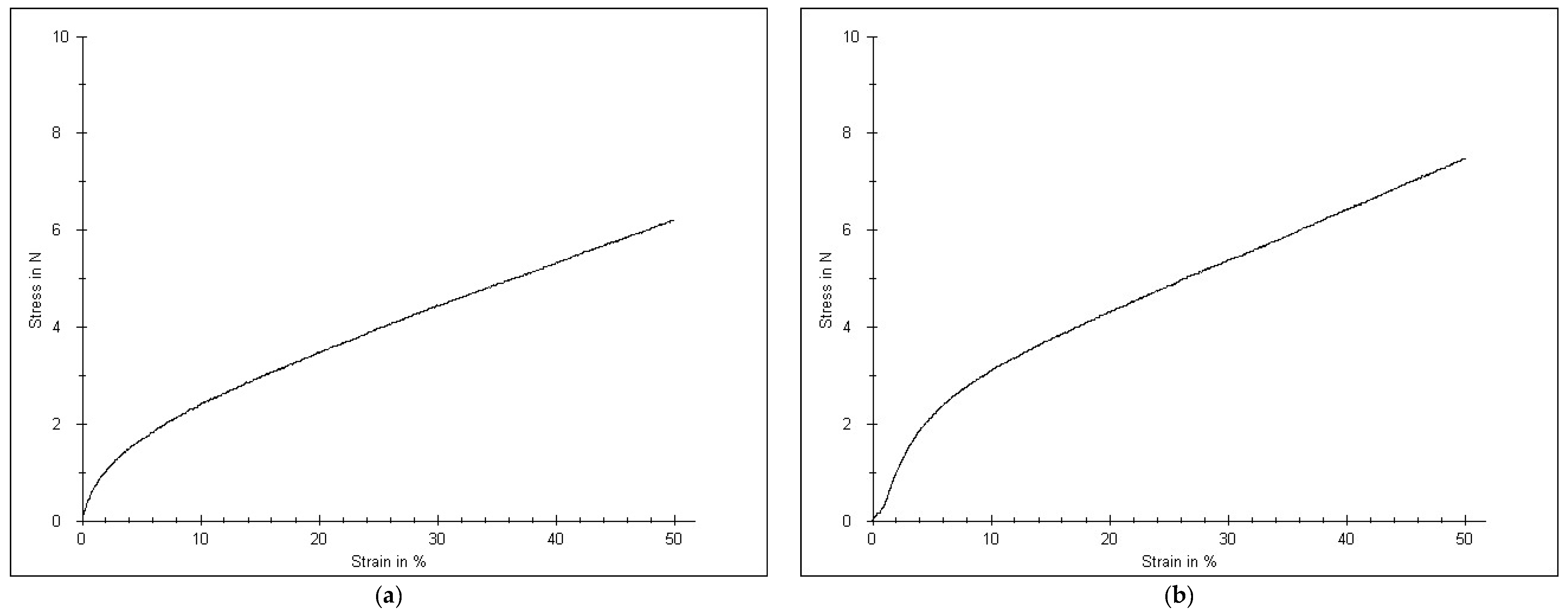
During the knitting of the experimental specimens, two main parameters that can theoretically influence the compression properties of knitted fabric were changed for each knitting pattern repeat (first group of specimens with the pattern repeat 3 × 1 and second group of specimens with the pattern repeat 1 × 1): loop density Pc and the feeding speed of the elastomeric yarn v. The results of the measured tensile force and compression, calculated according to Formula (1) at different elongation levels, are presented in Table 2. The average values of the compression presented in the Table 2 were calculated from five tests and, in all cases, the relative error did not exceed 5%. Characteristic stress–strain curves of the first and second groups of specimens are presented in Figure 3.
The target compression level is the second up to the third compression class according to standard RAL-GZ 387/1:2008 [20]. The limits of compression classes according to this standard are presented in mmHg (units of compression measurement); therefore, the same units of compression measurement are presented in the following figures, demonstrating the influence of different factors on the compression generated by elastomeric knitted structures. It was found that at 50% elongation, the compression generated by the majority of knitted variants was too high, i.e., it was close to the higher limit of the third compression class or even exceeded the limit to the fourth class.
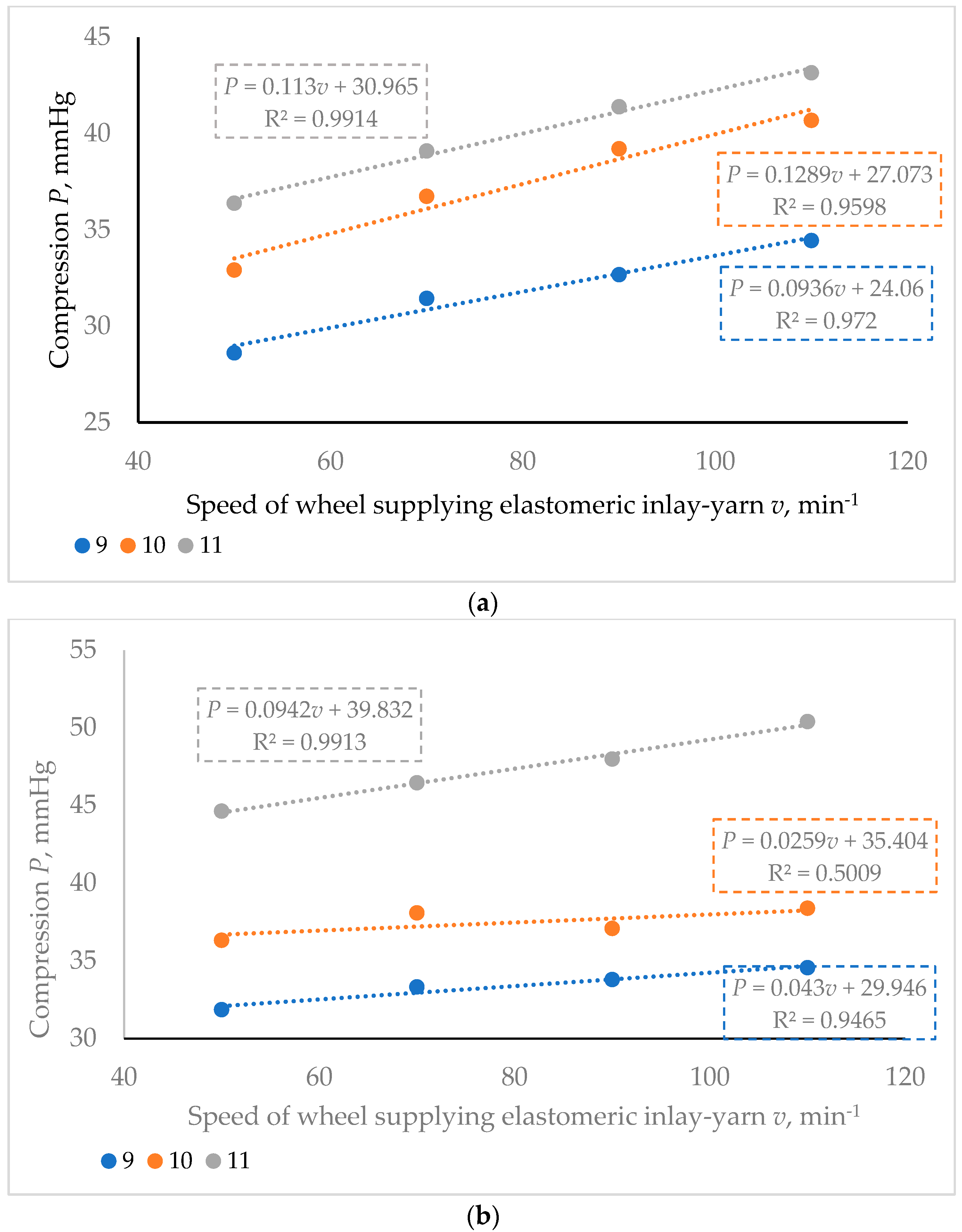
Figure 4 demonstrates the dependence of the compression generated at 50% elongation on the speed of the wheel supplying the elastomeric inlay-yarn into the knitting zone when three different variants of course density Pc are used. It must be underlined that only for the knits in the first group with the pattern repeat 3 × 1 (knits with a longer float of the elastomeric yarn) and only at the highest investigated elongation (50%) does the speed of elastomeric yarn supply into the knitting zone v (i.e., initial pre-tension of the elastomeric yarn before the formation of knitting elements) have a statistically significant influence on the generated compression P—the influence is more than 5%, i.e., it is higher than relative error of average values of compression tests. When the elongation is lower, the factor of the initial pre-tension of the elastomeric inlay-yarn used during the knitting plays an insignificant role in the compression level as the influence on the limits of relative error of average values varies, especially for the second group of knitted structures with the pattern repeat 1 × 1. It is due to the fact that the elastomeric inlay-yarn is laid as a float and tuck, during the stretching of the knitted specimen (in the limits of low elongation—up to 50%), the elastomeric yarn is not stretched at all or is very slightly stretched as the yarn is taken out of the yarn segment bent into the tuck. The smaller the pattern repeat—in other words, the shorter the float between two adjacent tucks in the pattern repeat—the smaller the influence of the inlay-yarn’s initial pre-tension, which is determined by the speed of the wheel supplying elastomeric inlay-yarn into the knitting zone. Similar results were found in [12].
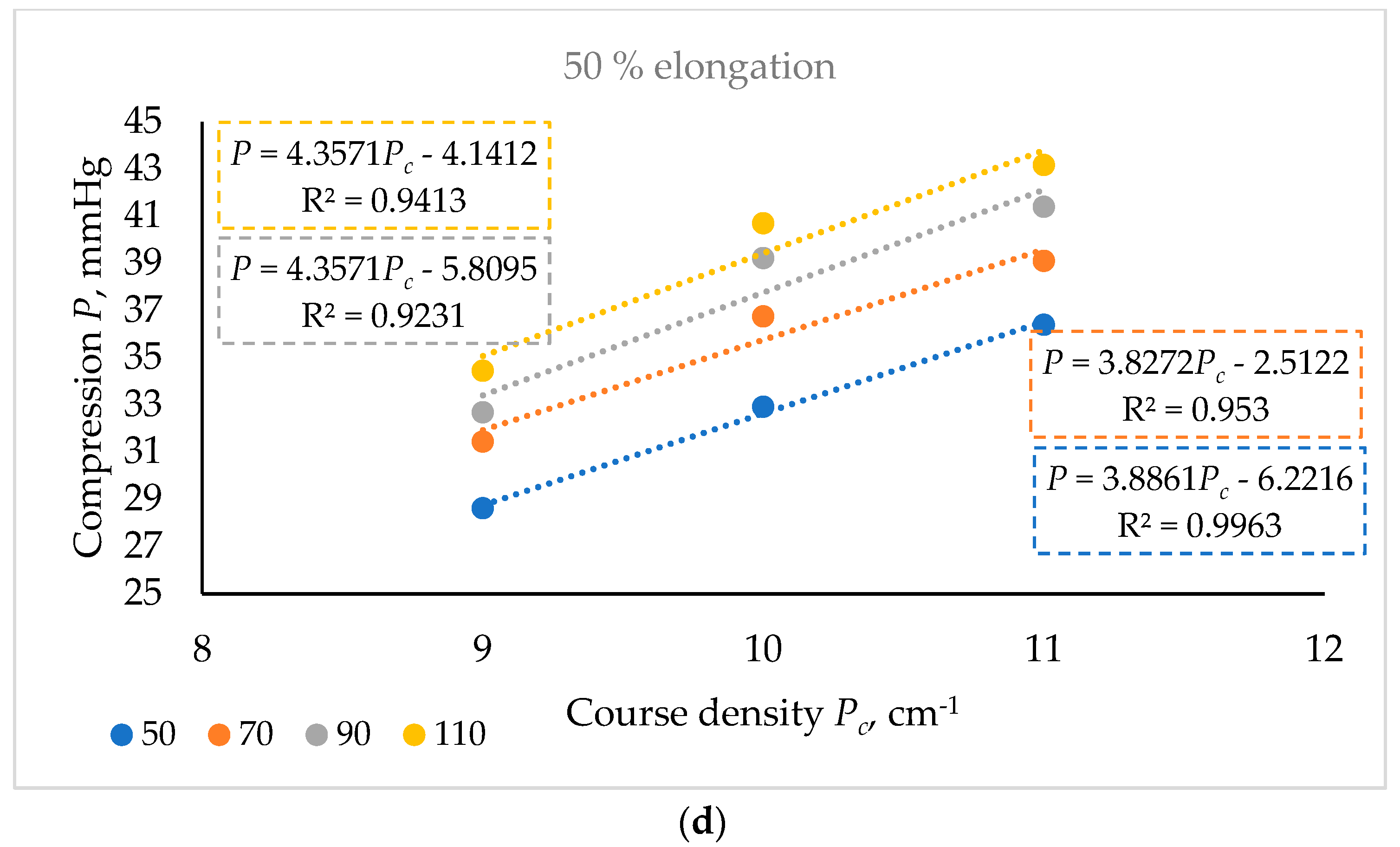
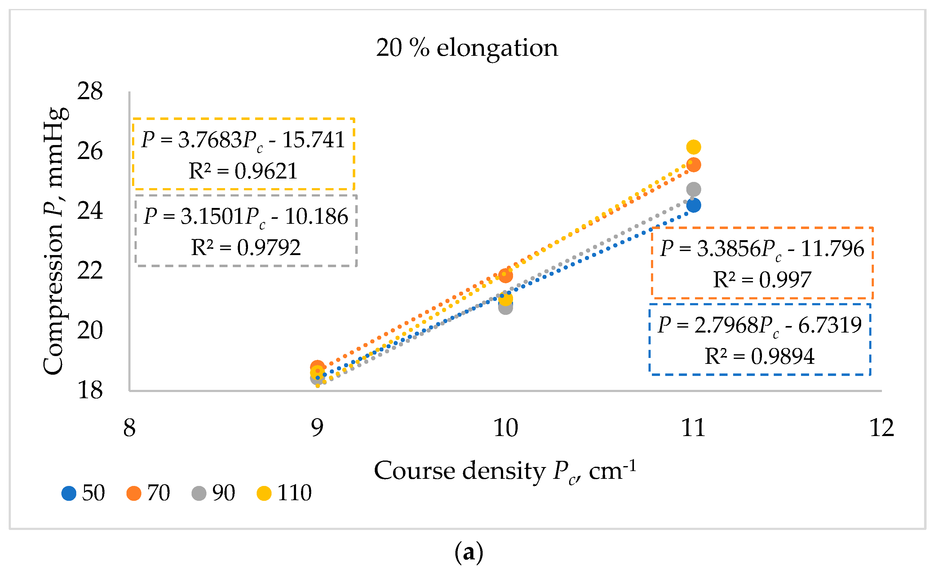
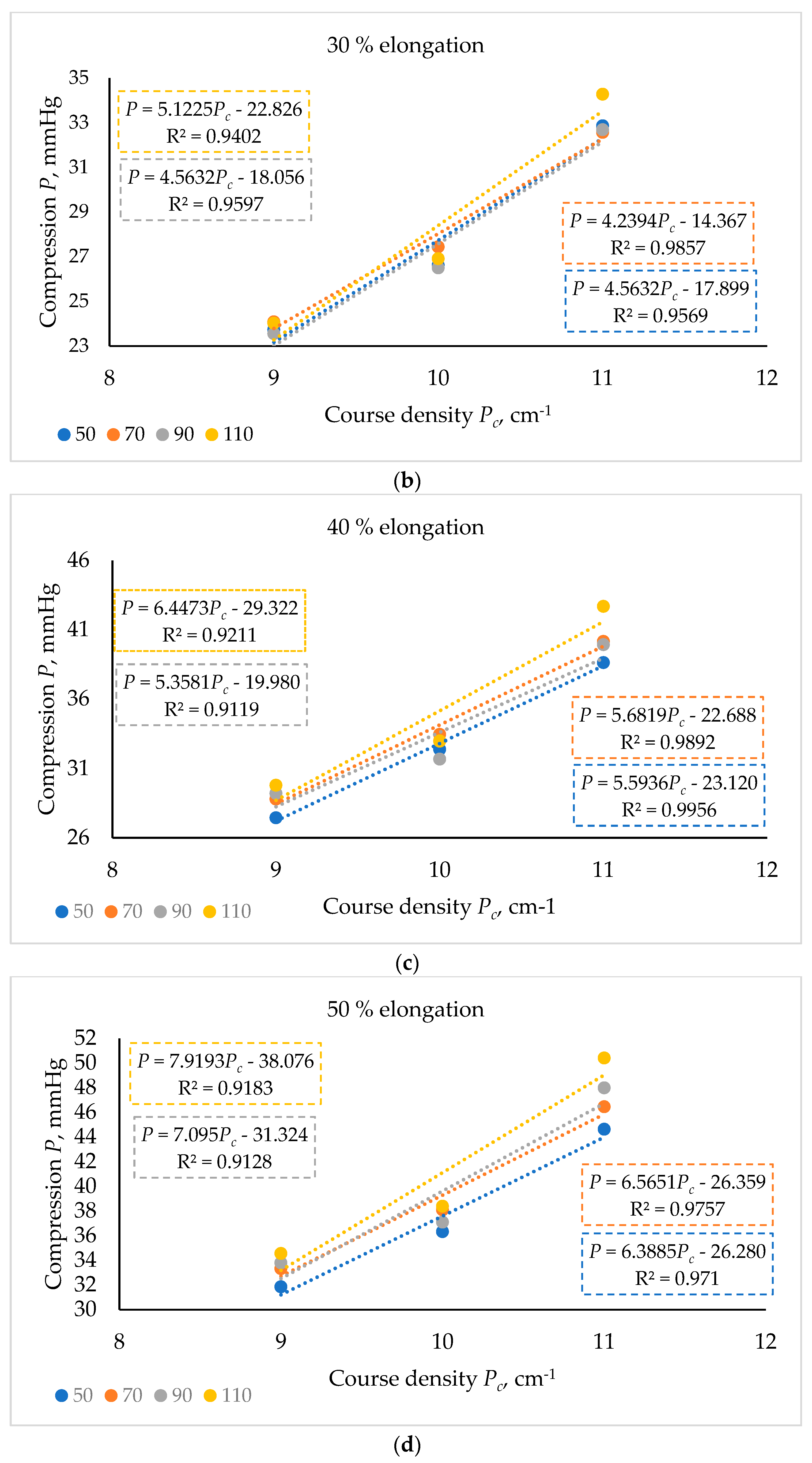
On the other hand, the influence of loop density on compression is obvious and it is characteristic for the knits made using both investigated knitting patterns. The linear dependence of compression P on loop density Pc is demonstrated by the results presented in Figure 5 and Figure 6. The coefficient of determination R2 for an absolute majority of the calculated curves is very high—higher than 0.9. The higher the density of the loops—that is, the shorter the knitting elements—the higher the compression at the same elongation level. In knitted structures with a higher loop density, the segments of yarns used for the formation of knitting elements (loops, tucks, floats) are shorter. Therefore, when a higher-density knit is stretched, the knitting elements straighten faster, and the effect of the tensile force falls on the straightened parts of the yarn. A higher tensile force is required to stretch the knit, so the knit generates higher compression.
Also, the data presented in Figure 5 demonstrate that the influence of the speed of elastomeric inlay-yarn supply to the knitting zone of the knits of the second group is insignificant, as was discussed earlier.
The results presented in Figure 5 and Figure 6 clearly demonstrate that the compression level at the same elongation can be increased by increasing the loop density of the knits.
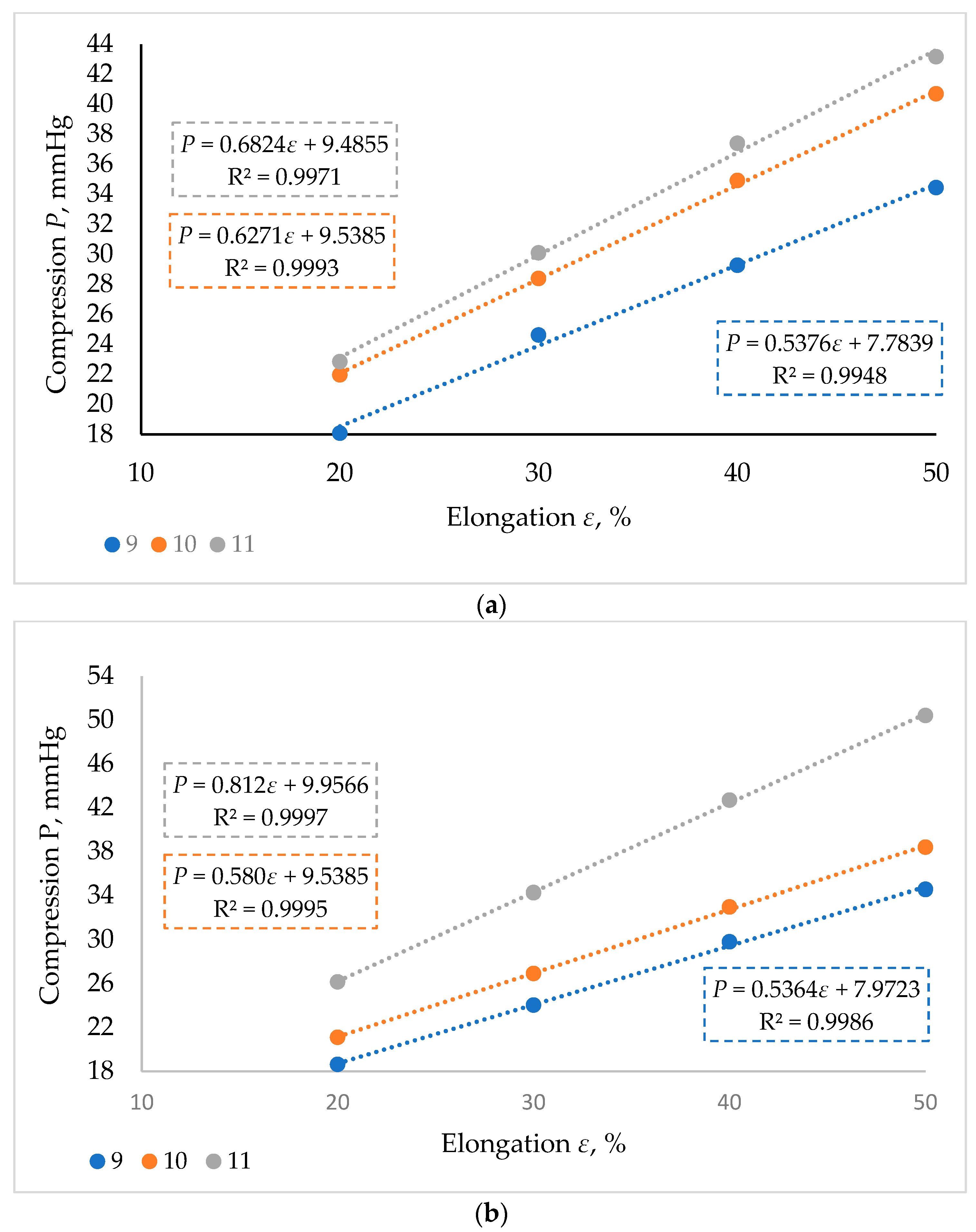
In earlier research works [14], it was found that at low elongations, the compression of elastomeric knits linearly depends on their elongation. This was also confirmed by this research. The nature of the stress–strain curves of both knitting pattern specimens presented in Figure 3 is linear in the elongation range from 10% to 50%. The results presented in Figure 7 clearly demonstrate that there is a strong correlation between compression P and elongation ε (up to 50%); in all cases, the coefficient of determination R2 is higher than 0.99. The percentage increase in compression with increasing elongation from 20% to 50% did not demonstrate a significant dependence on the knitting pattern repeat.
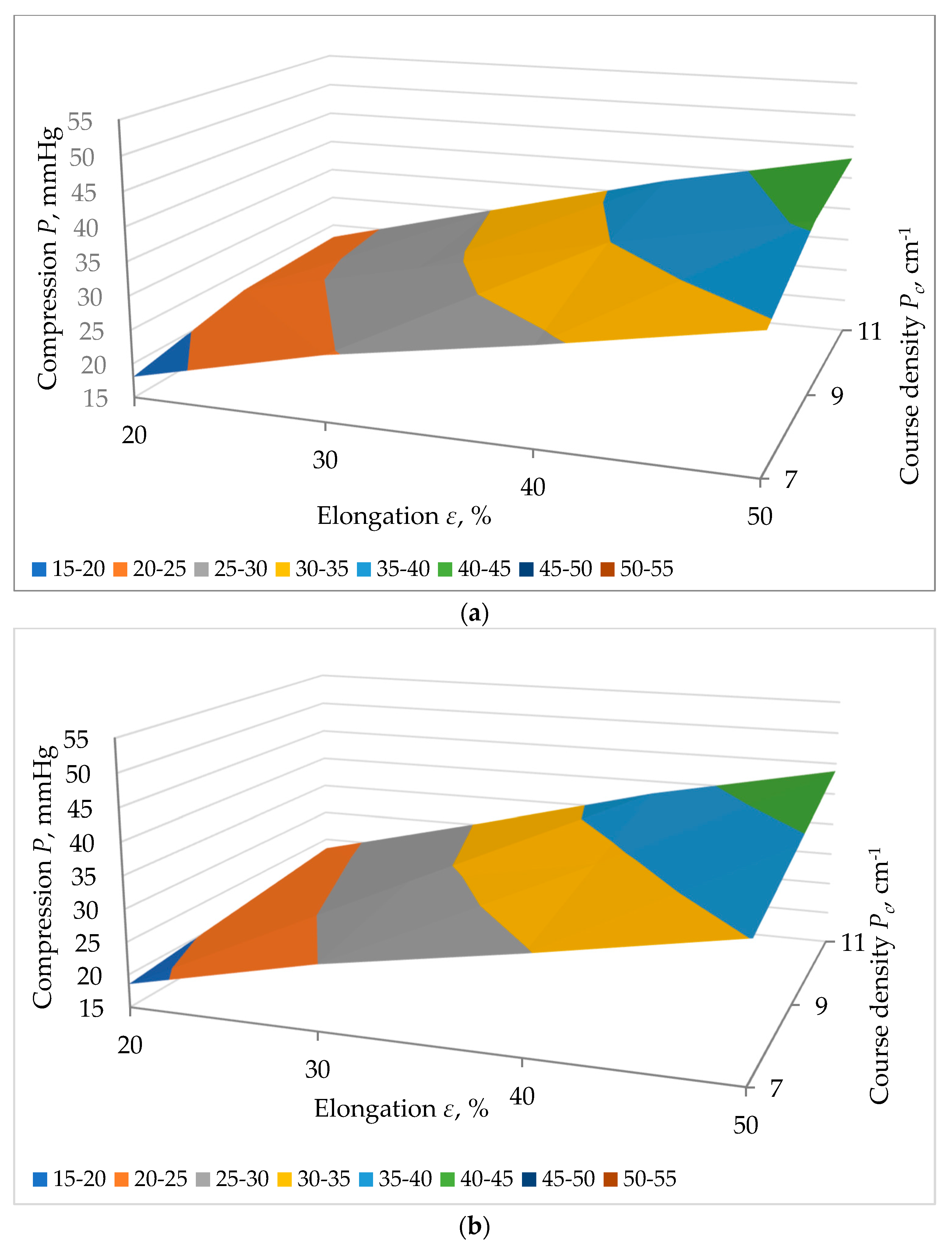
The summarized influence of both factors (course density Pc and elongation ε) on compression P is presented in Figure 8.
As can be seen from Figure 8, the experimental results give a very similar dependence as the results calculated theoretically according to the equations determined and presented in Figure 6 and Figure 7. The maximum error between the experimental and equation-calculated values within the entire range of variable factors did not exceed 3%. Therefore, it can be said that the established equations, presented in Figure 6 and Figure 7, can be used for compression prediction and knitting design of these specific products according to the required compression class by freely changing the values of both factors—elongation and loop density.

4. Conclusions

Twenty-four variants of knitted structures were developed for compression covers for the treatment of amputated limbs. Two main parameters that can theoretically influence the compression properties of knits—loop density and the feeding speed of the elastomeric inlay-yarn—were changed for each investigated knitting pattern repeat. It was found that one of the parameters—elastomeric yarn feeding speed—is insignificant for compression generated at low elongation (up to 50% for elastomeric knits). Therefore, this factor can be eliminated when designing weft-knitted compression covers. However, the influence of the second parameter—course density—on compression is significant and has a linear character. As loop density increases, the generated compression also increases. This research also confirmed that, in areas of low elongation (up to 50% for elastomeric knits), compression linearly depends on elongation, which appears to be due to the difference between the circumferences of the compression cover and the limb. The analysis of the summarized influence of both factors—course density and elongation—showed that equations of the correlation between compression and course density or elongation established during this research can be used for the prediction of compression during the knitting design, as the maximum error between the experimental and equation-calculated values within the entire range of variable factors did not exceed 3%.

Author Contributions

Conceptualization, D.M., L.M. and L.H.; methodology, G.L.; formal analysis, D.M., R.M. and L.H.; investigation, R.M., D.M., S.A., G.L. and L.H.; resources, L.M., S.A. and D.M.; writing—original draft preparation, D.M., G.L. and R.M.; writing—review and editing, D.M., R.M., G.L. and L.H.; supervision, D.M. All authors have read and agreed to the published version of the manuscript.

Funding

This research was funded by the LMTLT, grant number S-LU-24-5.

Data Availability Statement

Data are contained within the article.

Acknowledgments

This research was carried out within the framework of a joint Lithuanian–Ukraine science and research project, “Functional textile materials and products for the needs of the military, doctors, hospitalists and civilians (ORTOKNIT)”, supported by the Ministry of Education and Science of Ukraine and the Research Council of Lithuania (LMTLT).

Conflicts of Interest

The authors declare no conflicts of interest.

References

  1. Mikucioniene, D.; Halavska, L.; Melnyk, L.; Milašius, R.; Laureckiene, G.; Arabuli, S. Classification, Structure and Construction of Functional Orthopaedic Compression Knits for Medical Application: A Review. Appl. Sci. 2024, 14, 4486. [Google Scholar] [CrossRef]
  2. Struszczyk, M.H.; Olejnik, M. Assessment of Prospect of Textile Technologies for Medical Devices. Fibres Text. East. Eur. 2012, 20, 28–36. [Google Scholar]
  3. Tekin, S.; Kanat, S. The Effects of Sensory Marketing on Clothing-Buying Behavior. Autex Res. J. 2023, 23, 315–322. [Google Scholar] [CrossRef]
  4. Latanska, I.; Kowalski, K.; Klonowska, M.; Jaworska, A.; Dos, J.; Karbowski, K.; Sujka, W. Biological Properties of Knitted Fabrics Used in Post-Burn Scar Rehabilitation. Autex Res. J. 2022, 22, 343–349. [Google Scholar] [CrossRef]
  5. Shi, Y.; Liu, R.; Lv, J.; Ye, C. Biomedical therapeutic compression textiles: Physical-mechanical property analysis to precise pressure management. J. Mech. Behav. Biomed. Mater. 2024, 151, 106392. [Google Scholar] [CrossRef] [PubMed]
  6. Kankariya, N. Material, structure, and design of textile-based compression devices for managing chronic edema. J. Ind. Text. 2022, 52. [Google Scholar] [CrossRef]
  7. Liu, R.; Guo, X.; Lao, T.T.; Little, T. A critical review on compression textiles for compression therapy: Textile-based compression interventions for chronic venous insufficiency. Text. Res. J. 2017, 87, 1121–1141. [Google Scholar] [CrossRef]
  8. Alisauskiene, D.; Mikucioniene, D. Influence of the Rigid Element Area on the Compression Properties of Knitted Orthopaedic Supports. Fibres Text. East. Eur. 2012, 20, 103–107. [Google Scholar]
  9. Tsema, E.V.; Khomenko, I.P.; Bespalenko, A.A.; Buryanov, O.A.; Mishalov, V.G.; Kikh, A.Y. Clinico-Statistical Investigation of the Extremity Amputation Level in Wounded Persons. Klin. Khirurhiia 2017, 10, 324–331. [Google Scholar]
  10. Melnyk, L.; Halavska, L.; Mikucioniene, D.; Dudnyk, I.; Milasius, R. Assortment and Manufacturing Methods of Stump Socks. In Proceedings of the 11th International Young Researchers Conference Industrial Engineering 2024—From Zero to Hero, Kaunas, Lithuania, 9 May 2024; pp. 129–131. [Google Scholar]
  11. Murray, J.C. Keloids and hypertrophic scars. Clin. Dermatol. 1994, 12, 27–37. [Google Scholar] [CrossRef] [PubMed]
  12. Aboalasaad, A.R.; Sirkova, B.K.; Mansoor, T.; Skenderi, Z.; Khalil, A.S. Theoretical and Experimental Evaluation of Thermal Resistance for Compression Bandages. Autex Res. J. 2022, 22, 18–25. [Google Scholar] [CrossRef]
  13. Zhang, L.; Sun, G.; Li, J.; Chen, Y.; Chen, X.; Gao, W.; Hu, W. The structure and pressure characteristics of graduated compression stockings: Experimental and numerical study. Text. Res. J. 2019, 89, 5218–5225. [Google Scholar] [CrossRef]
  14. Alisauskiene, D.; Mikucioniene, D. Prediction of Compression of Knitted Orthopaedic Supports by Inlay-Yarn Properties. Mater. Sci. Medzg. 2014, 20, 311–314. [Google Scholar] [CrossRef]
  15. Yu, A.; Sukigara, S.; Takeuchi, S. Effect of inlaid elastic yarns and inlay pattern on physical properties and compression behaviour of weft-knitted spacer fabric. J. Ind. Text. 2022, 51, 2688S–2708S. [Google Scholar] [CrossRef]
  16. Muraliene, L.; Mikucioniene, D.; Laureckiene, G.; Brazaitis, M. New approach to evaluation of orthopaedic supports compression properties. J. Ind. Text. 2019, 49, 352–364. [Google Scholar] [CrossRef]
  17. LST EN ISO 13934-1:2013; Textiles—Tensile Properties of Fabrics—Part 1: Determination of Maximum Force and Elongation at Maximum Force Using the Strip Method. ISO: Geneva, Switzerland, 2000.
  18. LST EN ISO 139:2005; Textiles—Standard Atmospheres for Conditioning and Testing. ISO: Geneva, Switzerland, 2005.
  19. LST EN ISO 14971:2006; Textiles—Knitted Fabrics—Determination of Number of Stitches per Unit Length and Unit Area. iTeh, Inc.: San Francisco, CA, USA, 2006.
  20. RAL-GZ 387/1:2008; Medical Compression Hosiery, Quality Assurance. RAL Deutsches Institut für Gütesicherung and Kennzeichnung e.V.: Bonn, Germany, 2008.
Figure 1. Principal view and construction of knitted specimens: (a) 1st group of specimens with the pattern repeat 3 × 1; (b) 2nd group of specimens with the pattern repeat 1 × 1.
Fibers 12 00080 g001
Figure 2. Schematic diagram of the tensile testing machine.
Fibers 12 00080 g002
Figure 3. Stress–strain curve at 50% elongation of (a) 1st group of knits with the pattern repeat 3 × 1; (b) 2nd group of knits with the pattern repeat 1 × 1.
Fibers 12 00080 g003
Figure 4. Dependence of compression P (at 50% elongation) on the speed of elastomeric yarn supply v when course density is 9, 10, and 11 cm−1: (a) 1st group of knits with the pattern repeat 3 × 1; (b) 2nd group of knits with the pattern repeat 1 × 1.
Fibers 12 00080 g004
Figure 5. Dependence of compression P of 1st group of knits with pattern repeat 3 × 1 on course density Pc at different speeds of wheel supplying inlay-yarn (50, 70, 90, 110 min−1) at (a) 20% elongation; (b) 30% elongation; (c) 40% elongation; (d) 50% elongation.
Fibers 12 00080 g005aFibers 12 00080 g005b
Figure 6. Dependence of compression P of 2nd group of knits with pattern repeat 1 × 1 on course density Pc at different speeds of wheel supplying inlay-yarn (50, 70, 90, 110 min−1) at (a) 20% elongation; (b) 30% elongation; (c) 40% elongation; (d) 50% elongation.
Fibers 12 00080 g006aFibers 12 00080 g006b
Figure 7. Dependence of compression P on elongation ε at 110 min−1 speed of wheel supplying inlay-yarn of (a) 1st group of knits with the pattern repeat 3 × 1; (b) 2nd group of knits with the pattern repeat 1 × 1.
Fibers 12 00080 g007
Figure 8. Dependence of compression P on elongation ε and course density Pc of the 1st group of knits with the pattern repeat 3 × 1 (a—experimental; b—theoretically calculated) and 2nd group of knits with the pattern repeat 1 × 1 (c—experimental; d—theoretically calculated).
Fibers 12 00080 g008aFibers 12 00080 g008b
Table 1. Main structural characteristics and technical indicators of knitted specimens.
Sample CodeSpeed of Wheel Supplying Elastomeric Inlay-Yarn v, min−1Wale Density Pw, cm−1Course Density Pc, cm−1Area Density, M, g/m²Loop Length of Plating Cotton Yarn, mmLoop Length of Textured Elastomeric PA-EL Ground Yarn, mmAverage Length of Textured Elastomeric PA-EL Inlay-Yarn per One Wale, mm
1st group of specimens with the pattern repeat 3 × 1
3 × 1/11/50501111481.26.15.50.9
3 × 1/11/707010461.61.0
3 × 1/11/90909.5450.41.1
3 × 1/11/1101109450.01.2
3 × 1/10/50501110483.66.76.11.0
3 × 1/10/707010480.81.1
3 × 1/10/90909.5462.01.2
3 × 1/10/1101109456.81.3
3 × 1/9/5050119482.47.36.70.9
3 × 1/9/707010443.61.0
3 × 1/9/90909.5428.41.1
3 × 1/9/1101109417.61.2
2nd group of specimens with the pattern repeat 1 × 1
1 × 1/11/50501111410.85.65.20.9
1 × 1/11/707010410.21.0
1 × 1/11/90909409.21.0
1 × 1/11/1101108.5402.41.1
1 × 1/10/50501110414.46.25.80.9
1 × 1/10/707010404.01.0
1 × 1/10/90909390.81.1
1 × 1/10/1101108.5397.61.2
1 × 1/9/5050119423.26.86.40.8
1 × 1/9/707010416.00.9
1 × 1/9/90909403.21.0
1 × 1/9/1101108.5400.81.1
Table 2. Tensile force and compression of knitted specimens at different elongations.
Sample CodeTensile Force F, NCompression P, Pa
20%30%40%50%20%30%40%50%
3 × 1/9/502.793.604.404.862190.152826.003454.003815.10
3 × 1/10/503.054.004.655.592394.253140.003650.254388.15
3 × 1/11/503.364.305.206.182637.603375.504082.004851.30
3 × 1/9/703.033.844.585.342378.553014.403595.304191.90
3 × 1/10/703.384.305.296.242653.303375.504152.654898.40
3 × 1/11/703.594.635.726.642818.153634.554490.205212.40
3 × 1/9/902.933.854.765.552300.053022.253736.604356.75
3 × 1/10/903.484.735.696.662731.803713.054466.655228.10
3 × 1/11/903.735.006.047.032928.053925.004741.405518.55
3 × 1/9/1103.074.184.975.852409.953281.303901.454592.25
3 × 1/10/1103.734.825.936.912928.053783.704655.055424.35
3 × 1/11/1103.885.116.357.333045.804011.354984.755754.05
1 × 1/9/503.164.034.665.412480.603163.553658.104246.85
1 × 1/10/503.554.525.506.172786.753548.204317.504843.45
1 × 1/11/504.115.586.567.583226.354380.305149.605950.30
1 × 1/9/703.194.094.895.662504.153210.653838.654443.10
1 × 1/10/703.714.665.686.472912.353658.104458.805078.95
1 × 1/11/704.345.536.827.893406.904341.055353.706193.65
1 × 1/9/903.134.004.965.742457.053140.003893.604505.90
1 × 1/10/903.534.505.386.302771.053532.504223.304945.50
1 × 1/11/904.205.556.788.153297.004356.755322.306397.75
1 × 1/9/1103.164.085.065.872480.603202.803972.104607.95
1 × 1/10/1103.584.575.606.522810.303587.454396.005118.20
1 × 1/11/1104.445.827.258.563485.404568.705691.256719.60
Disclaimer/Publisher’s Note: The statements, opinions and data contained in all publications are solely those of the individual author(s) and contributor(s) and not of MDPI and/or the editor(s). MDPI and/or the editor(s) disclaim responsibility for any injury to people or property resulting from any ideas, methods, instructions or products referred to in the content.