

Propagation of Terahertz Surface Plasmon Polaritons in a Dielectric Fiber with a Metal Wire Core

Scientific and Technological Centre of Unique Instrumentation of the Russian Academy of Sciences, 117342 Moscow, Russia
Fibers 2022, 10(10), 89; https://doi.org/10.3390/fib10100089
Submission received: 11 September 2022
/
Revised: 14 October 2022
/
Accepted: 17 October 2022
/
Published: 19 October 2022
(This article belongs to the Special Issue Plasmonic Fibers—Metal-Dielectric Hybrid Schemes of Optic Fibers)
Abstract
:The influence of the conductivity and radius of metal wires embedded into the dielectric fiber on the velocity and attenuation length of terahertz surface plasmon polaritons has been theoretically investigated. It was shown that the phase velocities and attenuation lengths increase with increasing conductivity and radius of the wire. With increasing frequency, the velocity of surface plasmon waves increases and the propagation length decreases. The effect of the dielectric coating on the propagation velocity of surface electromagnetic waves is analyzed. It is shown that the coating leads to a decrease in the phase velocity and an increase in the propagation length of surface plasmon waves.
1. Introduction
The development of low-loss waveguides for transmitting terahertz radiation remains a challenging task. Waveguides with low losses and low dispersion are necessary for a new generation of terahertz systems. Conventional metal waveguides for microwave radiation and the dielectric fibers for visible light cannot be used in the THz range. Surface plasmon polaritons (SPPs) in the terahertz frequency range have very low losses and low dispersion. That is why much attention is paid to metal wire waveguides for use in sensing, imaging and spectroscopy [1,2,3,4]. In [2], the dispersive behavior of SPPs on cylindrical metal surfaces in the THz frequency range was investigated. It has been shown that the dispersive behavior of SPPs on a cylindrical metal surface at terahertz frequencies is quite different from the behavior of SPPs on a flat surface. In [3], the spatial and spectral distribution of the SPP’s field over the gold surface was measured. It was shown that the presence of a thin dielectric film on top of the metal affects the distribution of the SPP field, leading to strong confinement to the surface. In [4], measurements and calculations of the propagation of terahertz pulses along copper wires with and without a thin polyurethane coating are presented. In contrast to SPPs in the visible and infrared frequency range, the behavior of SPPs in the THz frequency range is happening in a different way [2]. Usually THz surface plasmon waves (SPWs) propagate at the interface between a metal and a dielectric. Recent studies have shown that THz SPWs can be observed in various systems. SPWs propagate along line-guided metallic structures, such as stripes, grooves, and gaps [5,6,7,8,9,10,11,12]. In [12], optimal parameters of gratings for sensing of polar and non-polar liquids were found at a wavelength of 130 µm. Reviews on terahertz technology and SPWs in the THz regime are presented in [13,14,15]. In the reviews [16,17], various terahertz optical fiber types including tube fibers, solid core fiber, anti-resonant fibers, porous-core fibers, metamaterial-based fibers, and their guiding mechanisms are examined.
In this paper, the propagation characteristics of SPPs in the THz frequency range in cylindrical metal wires with a dielectric coating are studied by solving Maxwell equations. The phase velocities and attenuation lengths of SPPs are determined as function of the conductivity and frequency for different wire radii.
2. Problem Formulation
In an optics regime, the electromagnetic beams can be effectively transmitted through the dielectric fibers [18,19,20]. The propagation of light beams in optical fibers is well described by the solutions of Maxwell equations [21,22,23,24,25]. SPWs propagating in optical fibers are also well known [26,27,28,29]. Although the dielectric fibers for visible light cannot be used for the transmission of terahertz electromagnetic waves, the methods used for the solution of Maxwell equations in an optical regime can also be applied for the consideration of THz radiation.
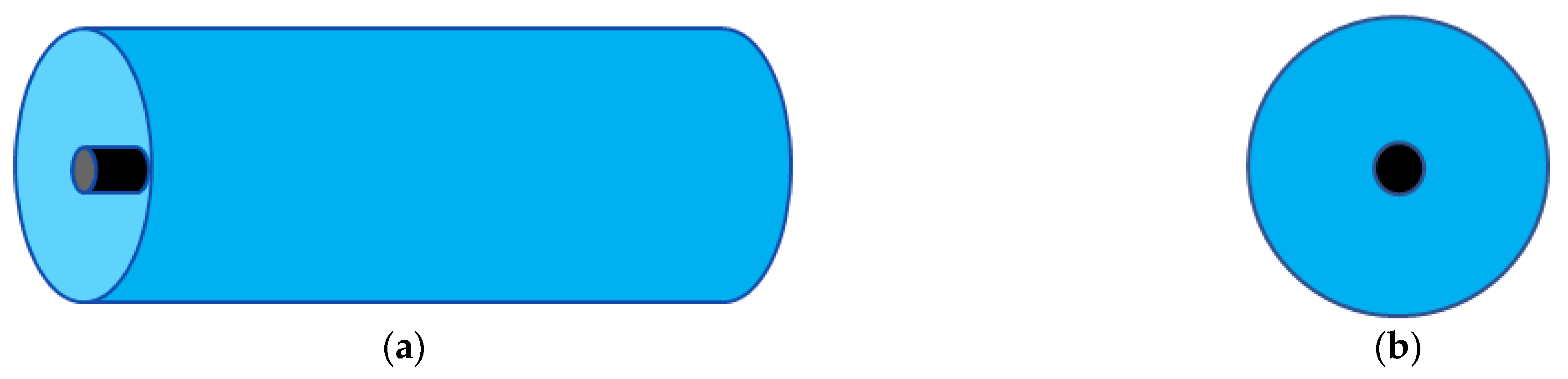
Consider a cylindrical plasmonic fiber (Figure 1), where a metal wire with radius is embedded in a dielectric fiber with radius .
It is well known that the surface electromagnetic waves can propagate along the conducting wire. A detailed theoretical analysis of surface waves propagating along a metal wire was carried out some time ago by Sommerfeld [30].
For the cylindrical structure of a dielectric fiber with a metal wire core, the guided modes may be determined from the Helmholtz equations for the longitudinal field component Ez [31]:
where , is the wavenumber in free space, is the longitudinal component of the wavenumber, is the metal wire radius, is the complex dielectric constant, where is the electric conductivity of the wire, is the resistance per unit length, is the dielectric constant of dielectric cover and is the dielectric constant of free space.
Solutions of Equation (1) are the Bessel functions:
where A1 and A2 are the amplitude coefficients, and are the modified Bessel functions of the first and second kind, , .
The propagation of the waves of a given frequency is determined by the propagation constatnt :
i.e., the spatial distribution of the electric field in the transverse plane is preserved when propagating along the wire. However, noticeable changes occur during the propagation of pulses. The fact is that the dependence of the velocity and attenuation length on the frequency leads to the dispersive pulse propagation.
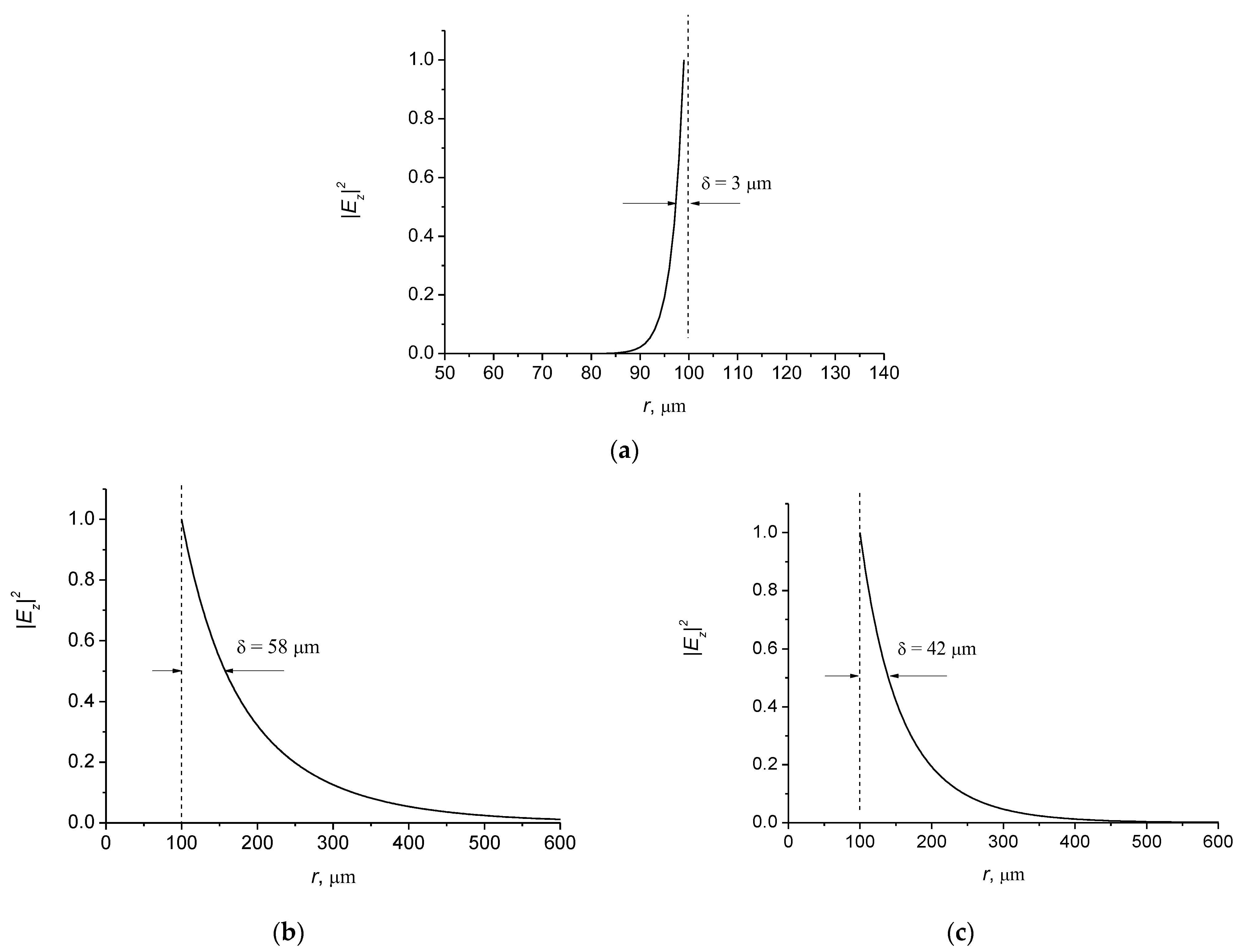
The wave fields (2) are localized near the metal-dielectric boundary (Figure 2), so the wave is a surface wave propagating along the metal wire boundary.
It is seen that the subwavelength confinement of the field at the wire-dielectric boundary takes place. Moreover, the localization of the field outside the wire is enhanced in the presence of a dielectric coating (Figure 2c). The thickness of skin layer is much less than the wavelength of the surface electromagnetic wave . It follows from (2) that the distribution of the electric field inside the wire does not depend on the permittivity of the dielectric coating , i.e., it does not depend on the properties of the coating.
The behavior of the electromagnetic field in the considered structure is described by the dispersion equation, which follows from the Maxwell equations. The dispersion equation for surface electromagnetic waves follows from the boundary condition of continuity for the tangential components of the field at :
where and are the modified Bessel functions of the first and second kind, accordingly, and are the derivatives of the Bessel functions, , , is the wavenumber in free space.
Phase and group velocities of the surface wave can be determined from the dispersion Equation (4).
The real part defines the phase velocity of the wave, and the group velocity is determined by . The imaginary part defines the attenuation length of the surface wave propagating along the plasmonic fiber.
3. Velocity and Propagation Distance of Surface Wave as Function of Wire Conductivity
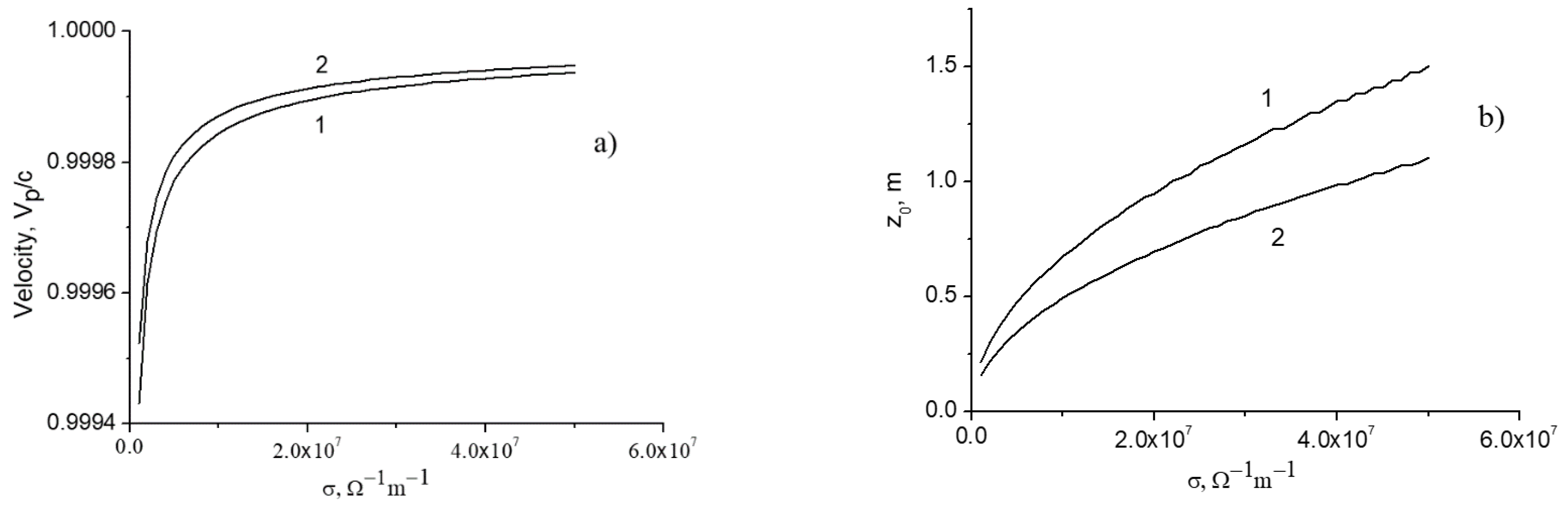
In Figure 3, the phase velocities and attenuation lengths of the surface wave depending on the conductivity of a wire with a radius of a = 100 µm for different frequencies of the THz surface plasmon wave are presented. Dielectric cladding is air with the refractive index n = 1. It follows from the simulation that the phase velocity increases with increasing conductivity and frequency. The propagation distance (attenuation length) of the surface wave also increases with increasing conductivity, but it decreases with increasing frequency (Figure 3b). Calculations show that the propagation length increases with the increase of the radius of a wire. The velocities of surface waves in metal wires with a dielectric coating decrease as , where c is the speed of light in free space, is the dielectric permittivity of a cladding.
Note that the conductivity of metal wires depends on the plasmon frequency of free electrons. It follows from a Drude formula for copper [5,32], that for the frequency of 0.5 THz. The conductivity of copper wire is σ = , and silver and gold wires have slightly higher conductivities.
The velocity of surface waves increases with frequency, as well as with the conductivity and radius of the wire. These waves are attenuated when propagating through the wire due to the skin effect. The dissipation increases with frequency due to a decrease in the thickness of the skin layer: . The propagation distance of surface waves decreases with the increase of the frequency due to dissipation (Figure 3b). However, this distance increases with increasing conductivity and the radius of the wire.
As follows from the calculations, the group velocity is greater than the phase velocity due to the anomalous dispersion in the electron plasma. Note that in a medium without dispersion, the group velocity of propagating modes is less than the phase velocity [33].
Effect of a Dielectric Coating
Consider the effect of the dielectric coating on the velocity and attenuation length of SPPs. Different glass and polymer materials were studied for terahertz fibers [16,17]. It follows from recent terahertz studies that polymers have lower absorption coefficients. In [34], the dielectric properties of polymers were characterized by transmission terahertz time-domain spectroscopy in the frequency range extending from 0.2 to 3.0 THz. In the calculations below, we use a constant refractive index n = 1.6 + 0.03i in the frequency ranges under consideration, which is consistent with the value for polyurethane given in [35]. The influence of the imaginary part of the refractive index of a dielectric coating on the velocity and attenuation length is also considered.
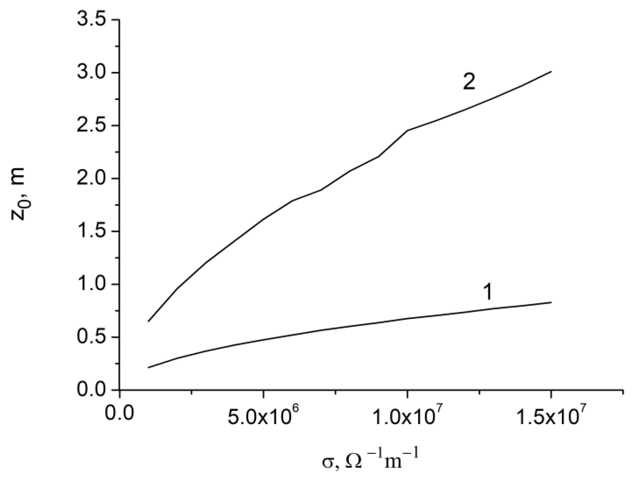
In Figure 4, the propagation distances of SPWs as a function of conductivity are shown for bare metal wire and coated metal wire.
It can be seen that the propagation distance in the coated metal wire increases in comparison with the metal-air boundary. Note that the propagation length will decrease if the dielectric coating has losses. For SPPs, it was found that guided THz pulses become strongly chirped when propagated through coated metal wires [4]. It has been experimentally demonstrated that the dielectric coating increases the propagation length [36].
In Figure 5, the velocities and attenuation lengths are presented as a function of frequency. It is seen that the velocity increases and the propagation length decreases with the frequency due to the dissipation of surface waves.
The physical reason of the increase of dissipation with frequency is the skin effect. The thickness of the skin layer decreases with frequency, and the resistance of the wire increases with frequency, thereby causing an increase in losses.
Figure 6 shows the attenuation lengths of 10 THz SPP depending on the conductivity for bare and coated metal wires with a radius of .
In Figure 7, the phase velocities and attenuation lengths as a function of conductivity are presented for different frequencies of SPW.
It is seen that the propagation velocity increases with the conductivity approaching the maximum value , where n = 1.6. The phase velocities for the frequencies 0.9 THz and 1.0 THz are almost the same, which indicates that the velocities for these frequencies are very close to the limit values .
In Figure 8, the velocities and attenuation lengths as a function of conductivity are presented for different frequencies of SPW.
It can be seen from Figure 8a, that for a given conductivity, the velocity is higher at a higher frequency. However, the attenuation length, on the contrary, is smaller for high frequencies (Figure 8b).
In Figure 9, the dependencies of the velocity and attenuation length on the conductivity are presented for different wire radii.
It follows from simulations that for a given conductivity, the velocity and the attenuation length are higher for a larger wire radius.
Figure 10 shows the velocities and attenuation lengths depending on the conductivity for different wire radii, taking into account the absorption in the dielectric coating. Here, the imaginary part of the dielectric permittivity of the coating is equal to , which corresponds to the effective material loss cm−1.
It follows from the simulation that absorption in a coating material has a negligible effect on the velocity of surface waves, but the attenuation lengths are significantly reduced. This indicates that the losses of the surface plasmon polariton wave in the dielectric coating are higher than in the metal wire. Currently, porous core photonic crystal fibers with a very low level of material loss have been proposed for pulse propagation [37,38,39]. These fibers have an effective material loss of less than 0.1 cm−1 at an operating frequency of f = 1 THz. In [39], a low-loss THz waveguide based on a photonic crystal structure with an average power loss of 0.02 cm−1 was designed and manufactured by 3D printing.
Thus, the effect of the conductivity of metal wires on propagation characteristics of SPPs was investigated. It is shown that the phase velocity of SPPs increase with the conductivity and frequency. The attenuation length of SPPs increases with the conductivity and decreases with the increase of the frequency. The main obstacle to transmitting a THz signal over long distances is losses in the dielectric coating. Therefore, the search for materials with low absorption is an important task.
Future research may be related to the consideration of the propagation of pulses and structured vector vortex SPPs modes in a plasmonic fiber. Of particular interest is the consideration of structured vortex beams with an orbital angular momentum [40,41,42,43,44,45] and the effects of the Goos-Hanchen shift [46,47,48]. Tunable resonance Goos-Hanchen and Imbert-Fedorov shifts for THz beams reflected from graphene plasmonic metasurfaces were studied in [46]. In [49], the axial magnetic field effects on the surface plasmon and bulk plasmon modes of cylindrical electric-gyrotropic wires are investigated.
4. Conclusions
In conclusion, the propagation characteristics of SPPs in the THz frequency range in cylindrical metal wires with a dielectric coating was studied by solving Maxwell equations. The velocities and attenuation lengths of SPPs are determined as a function of the conductivity and frequency for different wire radii. It is shown that the phase velocity of SPPs increase with the conductivity and frequency. The attenuation length of SPPs increases with the conductivity and decreases with the increase of the frequency. The subwavelength confinement of SPPs at the metal-dielectric boundary is shown.
The results can be applied in the field of THz imaging and spectroscopy, plasmonic fibers and in the development of various sensors, including gravitational wave detectors [50].
Funding
This research was funded by the Russian Foundation for Basic Research, project number 19-29-11026 and the Ministry of Science and Higher Education of the Russian Federation under the State contract No. FFNS-2022-0009.
Data Availability Statement
Not applicable.
Conflicts of Interest
The author declares no conflict of interest.
References
- Wang, K.; Mittleman, D.M. Metal wires for terahertz wave guiding. Nature 2004, 432, 376–379. [Google Scholar] [CrossRef] [PubMed]
- Wang, K.; Mittleman, D.M. Dispersion of surface plasmon polaritons on metal wires in the terahertz frequency range. Phys. Rev. Lett. 2006, 96, 157401. [Google Scholar] [CrossRef] [PubMed] [Green Version]
- Saxler, J.; Rivas, J.G.; Janke, C.; Pellemans, H.P.M.; Bolívar, P.H.; Kurz, H. Time-domain measurements of surface plasmon polaritons in the terahertz frequency range. Phys. Rev. B 2004, 69, 155427. [Google Scholar] [CrossRef]
- Van der Valk, N.C.J.; Planken, P.C.M. Effect of a dielectric coating on terahertz surface plasmon polaritons on metal wires. Appl. Phys. Lett. 2005, 87, 071106. [Google Scholar] [CrossRef] [Green Version]
- Cao, Q.; Jahns, J. Azimuthally polarized surface plasmons as effective terahertz waveguides. Opt. Express 2005, 13, 511–518. [Google Scholar] [CrossRef]
- Mitrofanov, O.; Harrington, J.A. Dielectric-lined cylindrical metallic THz waveguides: Mode structure and dispersion. Opt. Express 2010, 18, 1898–1903. [Google Scholar] [CrossRef]
- Chen, Y.; Song, Z.; Li, Y.; Hu, M.; Xing, Q.; Zhang, Z.; Chai, L.; Wang, C.Y. Effective surface plasmon polaritons on the metal wire with arrays of subwavelength grooves. Opt. Express 2006, 14, 13021–13029. [Google Scholar] [CrossRef]
- Akalin, T.; Treizebre, A.; Bocquet, B. Single-wire transmission lines at terahertz frequencies. IEEE Trans. Microw. Theory Tech. 2006, 54, 2762–2767. [Google Scholar] [CrossRef]
- Williams, C.R.; Andrews, S.R.; Maier, S.; Fernandez-Dominguez, A.I.; Martín-Moreno, L.; Garcia-Vidal, F. Highly confined guiding of terahertz surface plasmon polaritons on structured metal surfaces. Nat. Photonics 2008, 2, 175–179. [Google Scholar] [CrossRef]
- Rivas, J.G.; Kuttge, M.; Bolivar, P.H.; Kurz, H.; Sánchez-Gil, J.A. Propagation of surface plasmon polaritons on semiconductor gratings. Phys. Rev. Lett. 2004, 93, 256804. [Google Scholar] [CrossRef]
- Gan, C.H.; Chu, H.S.; Li, E.P. Synthesis of highly confined surface plasmon modes with doped graphene sheets in the midinfrared and terahertz frequencies. Phys. Rev. B 2012, 85, 125431. [Google Scholar] [CrossRef] [Green Version]
- Bulgakova, V.V.; Gerasimov, V.V.; Goldenberg, B.G.; Lemzyakov, A.G.; Malkin, A.M. Study of terahertz spoof surface plasmons on subwavelength gratings with dielectric substance in grooves. Phys. Procedia 2017, 201, 14–23. [Google Scholar] [CrossRef]
- Dhillon, S.S.; Vitiello, M.S.; Linfield, E.H.; Davies, A.; Hoffmann, M.; Booske, J.; Paoloni, C.; Gensch, M.; Weightman, P.; Williams, G.P.; et al. The 2017 terahertz science and technology roadmap. J. Phys. D Appl. Phys. 2017, 50, 043001. [Google Scholar] [CrossRef]
- Chen, S.H.; Chen, K.W.; Chu, K.R. A comparative study of single-wire and hollow metallic waveguides for terahertz waves. AIP Adv. 2018, 8, 115028. [Google Scholar] [CrossRef] [Green Version]
- Zhang, X.; Xu, Q.; Xia, L.; Li, Y.; Gu, J.; Tian, Z.; Ouyang, C.; Han, J.; Zhang, W. Terahertz surface plasmonic waves: A review. Adv. Photonics 2020, 2, 014001. [Google Scholar] [CrossRef]
- Atakaramians, A.; Afshar, S.V.; Monro, T.M.; Abbott, D. Terahertz dielectric waveguides. Adv. Opt. Photon. 2013, 5, 169–215. [Google Scholar] [CrossRef] [Green Version]
- Islam, M.S.; Cordeiro, C.M.B.; Franco, M.A.R.; Sultana, J.; Cruz, A.L.S.; Abbott, D. Terahertz optical fibers [Invited]. Opt. Express 2020, 28, 16089–16117. [Google Scholar] [CrossRef]
- Arnaud, J.A. Beam and Fiber Optics; Academic Press: New York, NY, USA, 1976. [Google Scholar]
- Marcuse, D. Light Transmission Optics; Van Nostrand Reinhold: New York, NY, USA, 1982. [Google Scholar]
- Snyder, A.W.; Love, J. Optical Waveguide Theory; Chapman and Hall: New York, NY, USA, 1983. [Google Scholar]
- Petrov, N.I. Evolution of polarization in an inhomogeneous isotropic medium. J. Exp. Theor. Phys. 1997, 85, 1085–1093. [Google Scholar] [CrossRef]
- Petrov, N.I. Depolarization of light in a graded-index isotropic medium. J. Mod. Opt. 1996, 43, 2239–2249. [Google Scholar] [CrossRef]
- Petrov, N.I. Evanescent and propagating fields of a strongly focused beam. J. Opt. Soc. Am. A 2003, 20, 2385–2389. [Google Scholar] [CrossRef]
- Petrov, N.I. Splitting of levels in a cylindrical dielectric waveguide. Opt. Lett. 2013, 38, 2020–2022. [Google Scholar] [CrossRef] [Green Version]
- Petrov, N.I. Depolarization of vector light beams on propagation in free space. Photonics 2022, 9, 162. [Google Scholar] [CrossRef]
- Pfeiffer, C.A.; Economou, E.N.; Ngai, K.L. Surface polaritons in a circularly cylindrical interface: Surface plasmons. Phys. Rev. B 1974, 10, 3038–3051. [Google Scholar] [CrossRef]
- Novotny, L.; Hafner, C. Light propagation in a cylindrical waveguide with a complex, metallic, dielectric function. Phys. Rev. E 1994, 50, 4094–4106. [Google Scholar] [CrossRef] [PubMed]
- Khosvari, H.; Tilley, D.R.; Loudon, R. Surface polaritons in cylindrical optical fibers. J. Opt. Soc. Am. A 1991, 8, 112–122. [Google Scholar]
- Al-Bader, S.J.; Imtaar, M. Optical fiber hybrid-surface plasmon polaritons. J. Opt. Soc. Am. B 1993, 10, 83–88. [Google Scholar] [CrossRef]
- Sommerfeld, A. Ueber die Fortpflanzung elektrodynamischer Wellen längs eines Drahtes. Ann. Phys. 1899, 303, 233–290. [Google Scholar] [CrossRef] [Green Version]
- Petrov, N.I. Synchrotron mechanism of X-ray and gamma-ray emissions in lightning and spark discharges. Sci. Rep. 2021, 11, 19824. [Google Scholar] [CrossRef]
- Ordal, M.A.; Bell, R.J.; Alexander, R.W.; Long, L.L.; Querry, M.R. Optical properties of fourteen metals in the infrared and far infrared: Al, Co, Cu, Au, Fe, Pb, Mo, Ni, Pd, Pt, Ag, Ti, V, and W. Appl. Opt. 1985, 24, 4493–4499. [Google Scholar] [CrossRef] [PubMed]
- Petrov, N.I. Speed of structured light pulses in free space. Sci. Rep. 2019, 9, 18332. [Google Scholar] [CrossRef] [PubMed] [Green Version]
- Jin, Y.S.; Kim, G.J.; Jeon, S.G. Terahertz Dielectric Properties of Polymers. J. Korean Phys. Soc. 2006, 49, 513–517. [Google Scholar]
- Stefani, A.; Skelton, J.H.; Tuniz, A. Bend losses in flexible polyurethane antiresonant terahertz waveguides. Opt. Express 2021, 29, 28692–28703. [Google Scholar] [CrossRef]
- Gerasimov, V.V.; Knyazev, B.A.; Lemzyakov, A.G.; Nikitin, A.K.; Zhizhin, G.N. Growth of terahertz surface plasmon propagation length due to thin-layer dielectric coating. J. Opt. Soc. Am. B 2016, 33, 2196–2203. [Google Scholar] [CrossRef]
- Paul, B.K.; Bhuiyan, T.; Abdulrazak, L.F.; Sarker, K.; Hassan, M.M.; Shariful, S.; Ahmed, K. Extremely low loss optical waveguide for terahertz pulse guidance. Results Phys. 2019, 15, 102666. [Google Scholar] [CrossRef]
- Yudasari, N.; Anthony, J.; Leonhardt, R. Terahertz pulse propagation in 3D-printed waveguide with metal wires component. Opt. Express 2014, 22, 26042–26054. [Google Scholar] [CrossRef]
- Yang, J.; Zhao, J.; Gong, C.; Tian, H.; Sun, L.; Chen, P.; Lin, L.; Liu, W. 3D printed low-loss THz waveguide based on Kagome photonic crystal structure. Opt. Express 2016, 24, 22454–22460. [Google Scholar] [CrossRef] [PubMed]
- Stefani, A.; Fleming, S.C.; Kuhlmey, B.T. Terahertz orbital angular momentum modes with flexible twisted hollow core antiresonant fiber. APL Photonics 2018, 3, 051708. [Google Scholar] [CrossRef] [Green Version]
- Petrov, N.I. Vector and tensor polarizations of light beams. Laser Phys. 2008, 18, 522–525. [Google Scholar] [CrossRef]
- Petrov, N.I. Spin-orbit and tensor interactions of light in inhomogeneous isotropic media. Phys. Rev. A 2013, 88, 023815. [Google Scholar] [CrossRef]
- Petrov, N.I. Spin-dependent transverse force on a vortex light beam in an inhomogeneous medium. JETP Lett. 2016, 103, 443–448. [Google Scholar] [CrossRef]
- Petrov, N.I. Vector Laguerre–Gauss beams with polarization-orbital angular momentum entanglement in a graded-index medium. J. Opt. Soc. Am. A 2016, 33, 1363–1369. [Google Scholar] [CrossRef] [PubMed] [Green Version]
- Petrov, N.I. Depolarization of Light in Optical Fibers: Effects of Diffraction and Spin-Orbit Interaction. Fibers 2021, 9, 34. [Google Scholar] [CrossRef]
- Farmani, A.; Miri, M.; Sheikhi, M.H. Tunable resonant Goos–Hänchen and Imbert–Fedorov shifts in total reflection of terahertz beams from graphene plasmonic metasurfaces. J. Opt. Soc. Am. B 2017, 34, 1097–1106. [Google Scholar] [CrossRef]
- Petrov, N.I.; Danilov, V.A.; Popov, V.V.; Usievich, B.A. Large positive and negative Goos-Hänchen shifts near the surface plasmon resonance in subwavelength grating. Opt. Express 2020, 28, 7552–7564. [Google Scholar] [CrossRef] [PubMed]
- Kan, X.F.; Zou, Z.X.; Yin, C.; Xu, H.P.; Wang, X.P.; Han, Q.B.; Cao, Z.Q. Continuous Goos-Hänchen Shift of Vortex Beam via Symmetric Metal-Cladding Waveguide. Materials 2022, 15, 4267. [Google Scholar] [CrossRef]
- Moradi, A. Surface and bulk plasmons in cylindrical electric-gyrotropic wires. J. Opt. Soc. Am. B 2020, 37, 2947–2955. [Google Scholar] [CrossRef]
- Petrov, N.I.; Pustovoit, V.I. Small-sized interferometer with Fabry-Perot resonators for gravitational wave detection. Sensors 2021, 21, 1877. [Google Scholar] [CrossRef]
Figure 1.
The schematic view of a dielectric fiber with a metal wire core (a) and its cross section (b).
Figure 1.
The schematic view of a dielectric fiber with a metal wire core (a) and its cross section (b).

Figure 2.
Field intensity distributions at the wire-dielectric boundary. (a)—inside wire; (b,c)—outside wire; σ = , , λ = 2.1 mm.
Figure 2.
Field intensity distributions at the wire-dielectric boundary. (a)—inside wire; (b,c)—outside wire; σ = , , λ = 2.1 mm.

Figure 3.
The phase velocity (a) and attenuation length (b) as function of conductivity. 1—ω = 0.9 THz, 2—ω = 1.1 THz.
Figure 3.
The phase velocity (a) and attenuation length (b) as function of conductivity. 1—ω = 0.9 THz, 2—ω = 1.1 THz.

Figure 4.
The attenuation length as a function of conductivity. ω = 0.9 THz; 1—bare metal wire, 2—coated metal wire. .
Figure 4.
The attenuation length as a function of conductivity. ω = 0.9 THz; 1—bare metal wire, 2—coated metal wire. .

Figure 5.
The phase velocity (a) and attenuation length (b) as a function of frequency. σ = 1.5.
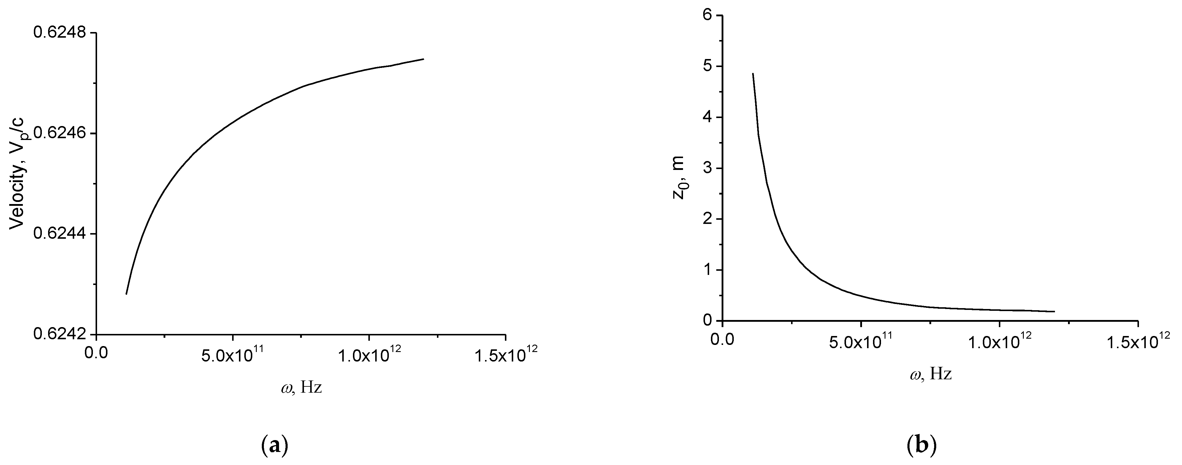
Figure 6.
The attenuation length as a function of conductivity. , 1—air; 2—coated metal wire.
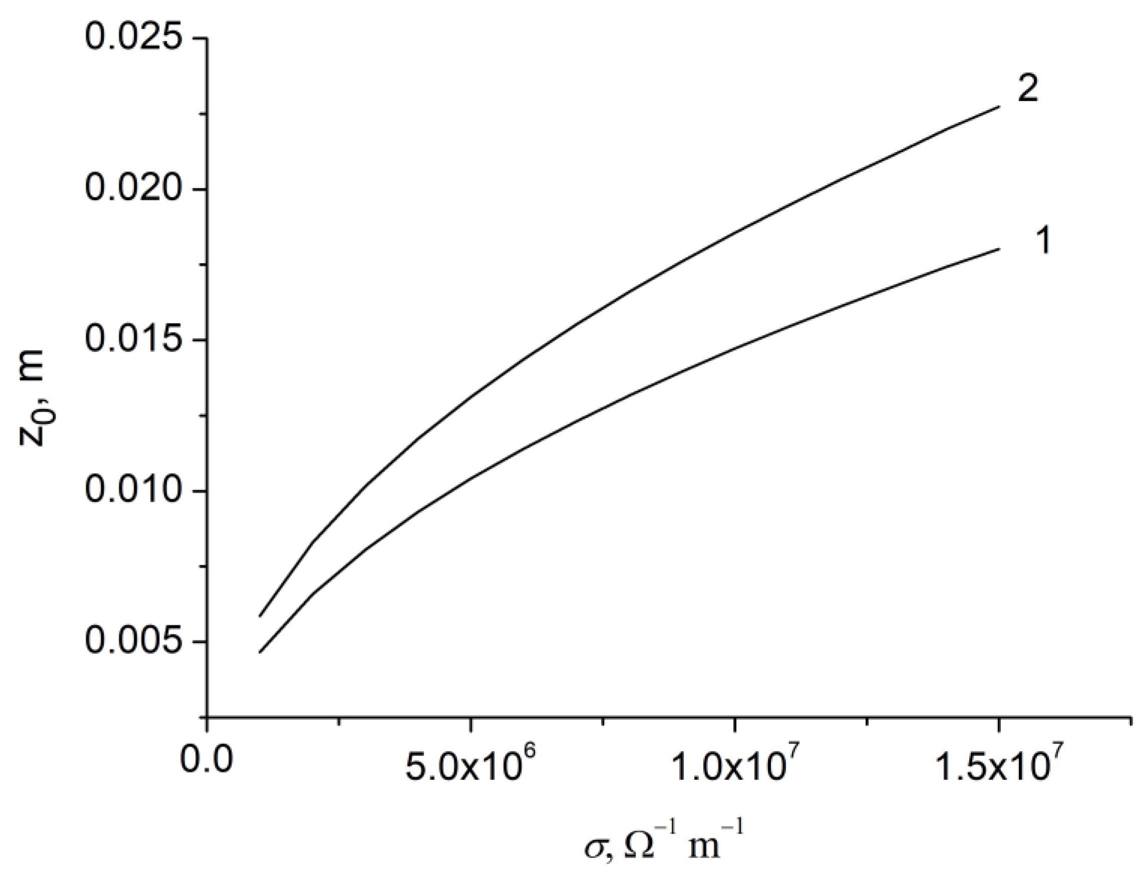
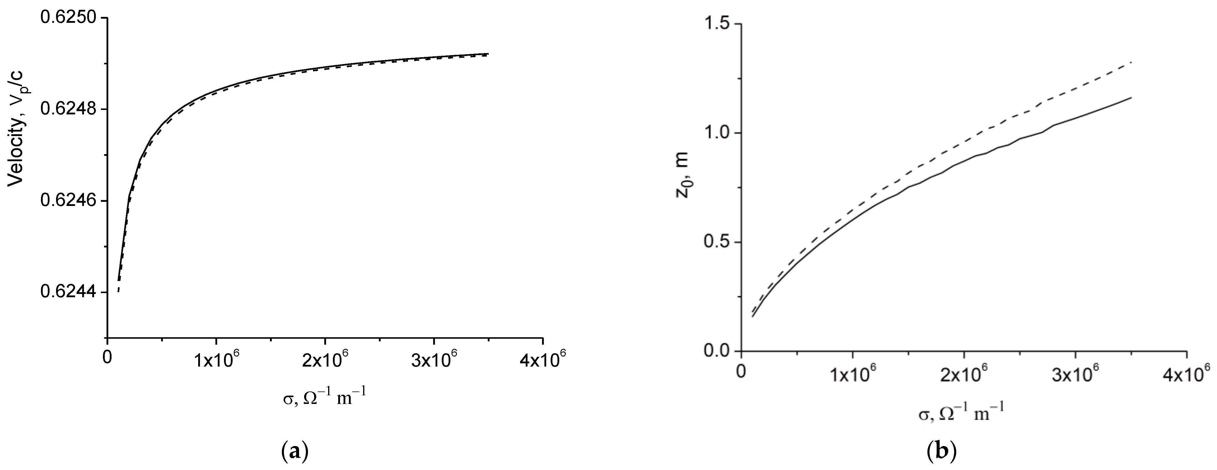
Figure 7.
The phase velocity (a) and attenuation length (b) as a function of conductivity. Dashed line line—ω = 0.9 THz, solid line—ω = 1.0 THz.
Figure 7.
The phase velocity (a) and attenuation length (b) as a function of conductivity. Dashed line line—ω = 0.9 THz, solid line—ω = 1.0 THz.

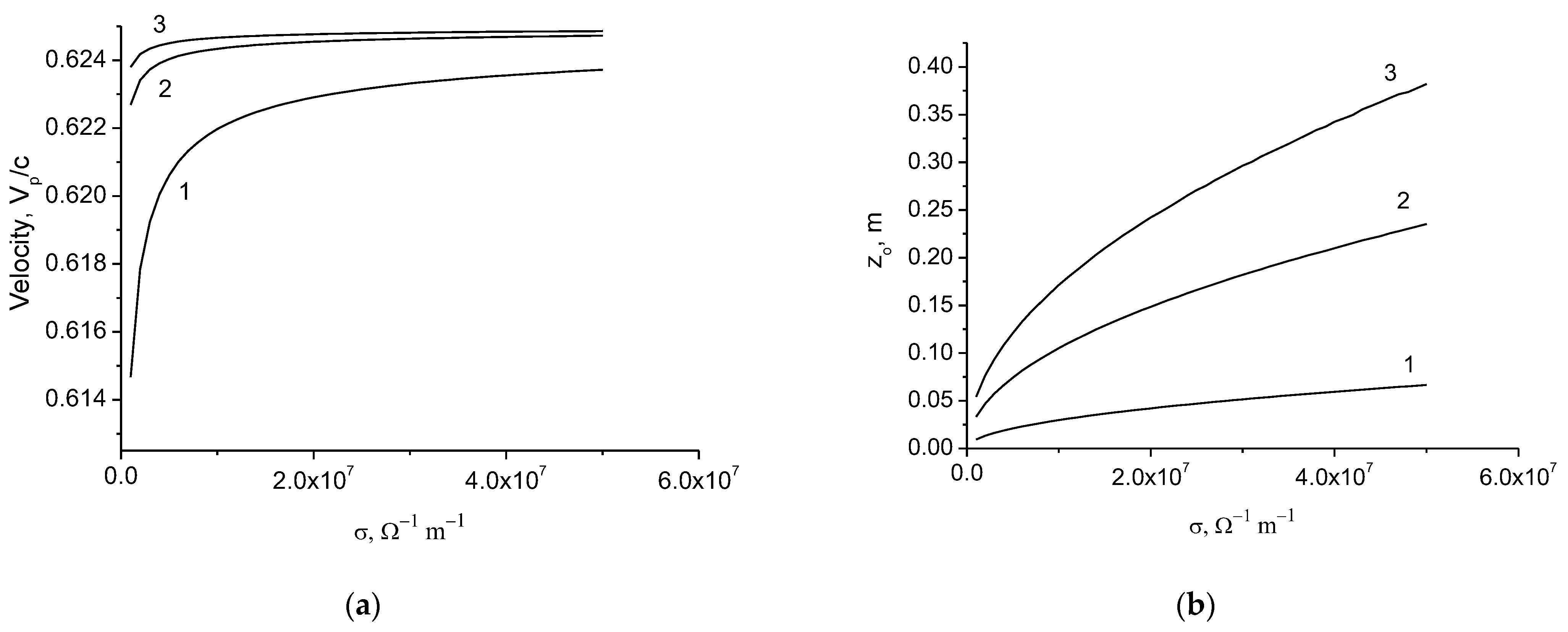
Figure 8.
The velocities (a) and attenuation lengths (b) as a function of conductivity. 1—ω = 1 THz; 2—ω = 5 THz; 3—ω = 10 THz; .
Figure 8.
The velocities (a) and attenuation lengths (b) as a function of conductivity. 1—ω = 1 THz; 2—ω = 5 THz; 3—ω = 10 THz; .
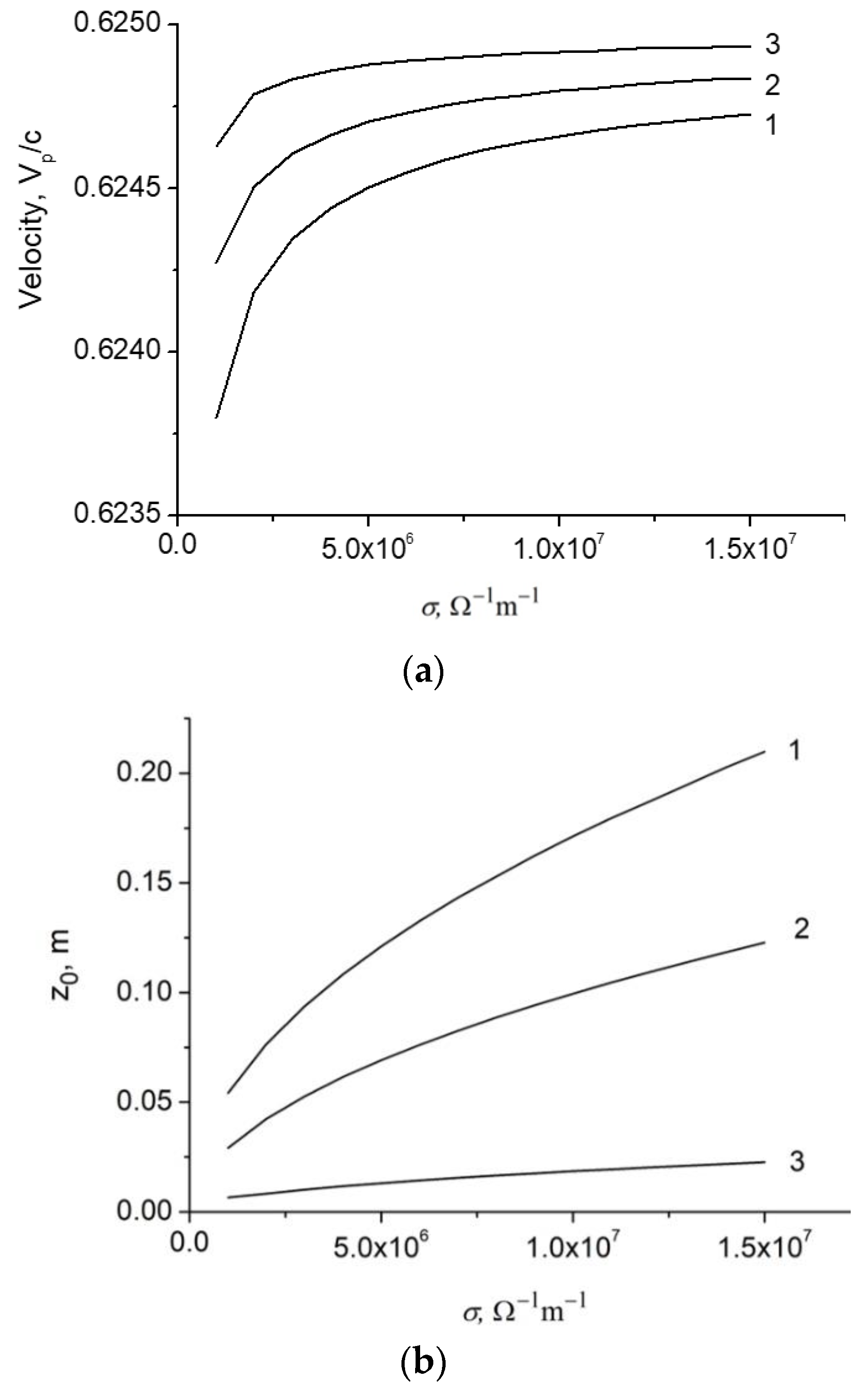
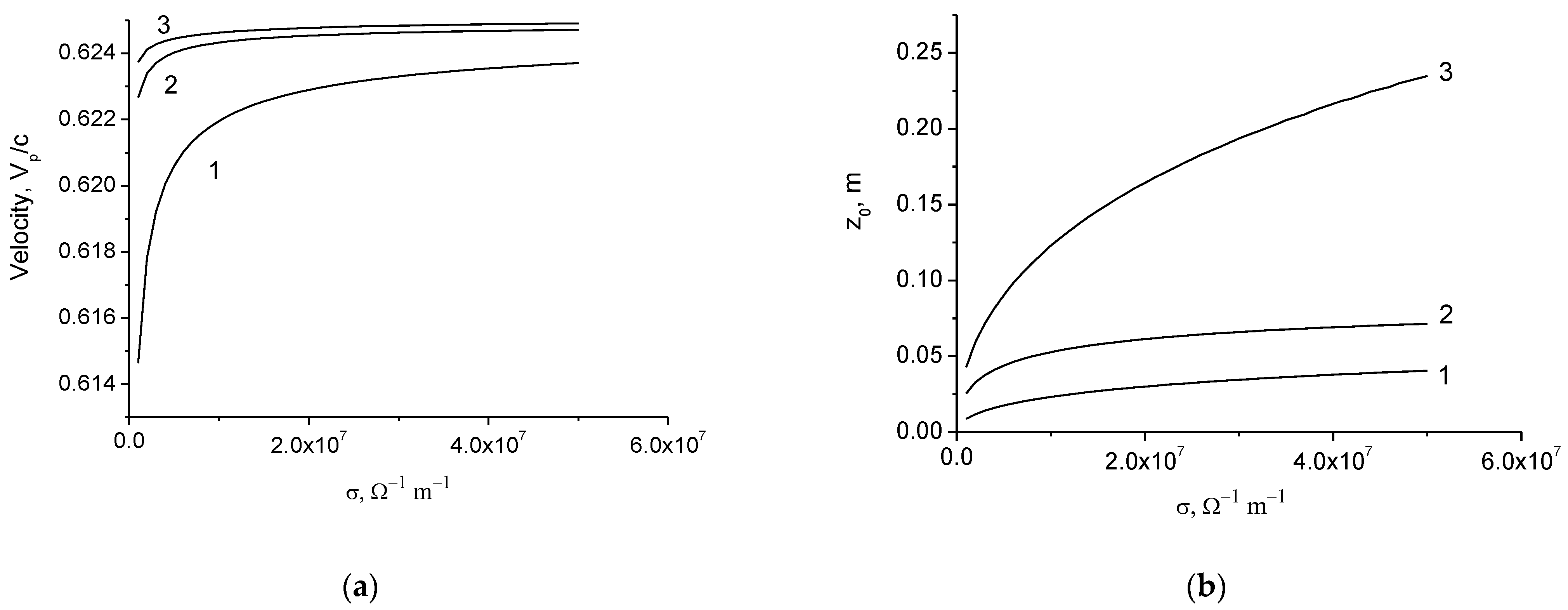
Figure 9.
The velocities (a) and attenuation lengths (b) as a function of conductivity. ω = 1 THz; 1— ; 2—; 3—. .
Figure 9.
The velocities (a) and attenuation lengths (b) as a function of conductivity. ω = 1 THz; 1— ; 2—; 3—. .

Figure 10.
The velocities (a) and attenuation lengths (b) as a function of conductivity. ω = 1 THz; 1—; 2—; 3—. .
Figure 10.
The velocities (a) and attenuation lengths (b) as a function of conductivity. ω = 1 THz; 1—; 2—; 3—. .

Publisher’s Note: MDPI stays neutral with regard to jurisdictional claims in published maps and institutional affiliations. |
© 2022 by the author. Licensee MDPI, Basel, Switzerland. This article is an open access article distributed under the terms and conditions of the Creative Commons Attribution (CC BY) license (https://creativecommons.org/licenses/by/4.0/).
Share and Cite
MDPI and ACS Style
Petrov, N.I. Propagation of Terahertz Surface Plasmon Polaritons in a Dielectric Fiber with a Metal Wire Core. Fibers 2022, 10, 89. https://doi.org/10.3390/fib10100089
AMA Style
Petrov NI. Propagation of Terahertz Surface Plasmon Polaritons in a Dielectric Fiber with a Metal Wire Core. Fibers. 2022; 10(10):89. https://doi.org/10.3390/fib10100089
Chicago/Turabian StylePetrov, Nikolai I. 2022. "Propagation of Terahertz Surface Plasmon Polaritons in a Dielectric Fiber with a Metal Wire Core" Fibers 10, no. 10: 89. https://doi.org/10.3390/fib10100089
Note that from the first issue of 2016, this journal uses article numbers instead of page numbers. See further details here.