Numerical Study on the Optimization of Roll-to-Roll Ultraviolet Imprint Lithography


1
Department of Cogno-Mechatronics Engineering, Pusan National University, Busan 46241, Korea
2
Department of Opto-Mechatronics Engineering, Pusan National University, Busan 46241, Korea
*
Author to whom correspondence should be addressed.
Coatings 2019, 9(9), 573; https://doi.org/10.3390/coatings9090573
Submission received: 6 August 2019
/
Revised: 2 September 2019
/
Accepted: 3 September 2019
/
Published: 8 September 2019
(This article belongs to the Special Issue Modelling and Simulation of Coating 2019)
Abstract
:Roll-to-roll ultraviolet (R2R-UV) imprinting is a low-cost and high-throughput method that includes the manufacturing of large-area functional films. However, the quality of the final product is obstructed by the bubble entrapment during the imprinting process. In this study, a multi-phase volume of fluid (VOF) numerical model was used to remove bubble entrapment during the R2R imprinting process, which covered all parameters. This new modified numerical model with open-channel boundary conditions was based on the single zone that contains the direct contact of UV resin with the imprinting mold during the filling process. In addition, this model simulated the UV resin filling into microcavities at the preceding and succeeding ends of the imprinting mold. Different patterns of imprinting mold were considered to enhance the fidelity of R2R-UV imprinting for the comprehensive analysis. The experimental results validated through numerical simulations revealed that the bubble entrapment can be controlled by varying various parameters such as speed of the imprinting system, viscosity, contact angles, and pattern shape. The proposed model may be useful for a continuous bubble-free R2R imprinting process in industrial applications that includes flexible displays and micro/nano-optics.
1. Introduction
The nano-patterning techniques for nano-imprint lithography (NIL) have attracted many research groups due to its practical implication on an industrial scale. Ahn et al. [1] were the pioneers who introduced roll-to-roll ultraviolet nano-imprint lithography (R2R-UV-NIL) by replicating lenticular lens patterns on polyethylene terephthalate (PET) substrate. R2R-UV-NIL is one of the most promising technologies that fabricate low-cost, high-throughput, and large-area micro/nano features on functional films. R2R-UV-NIL is a process-based batch NIL used to replicate nano/micro-scale patterns from a surface of the patterned mold to a large area of the flexible or rigid substrate. Due to wide applications of R2R-UV-NIL in several fields, it has been studied broadly by numerous researchers working in the area of electronic devices [2], polarizers [3], transistors [4], and solar cells [5], etc. On the commercial scale, productivity in the development of flat display panels [6], biotechnological applications [7], and optoelectronic devices [8] is yet to meet with standards. High fidelity and productivity in NIL represent the complete filling of resin in nano/microcavities or exact replication of imprint patterns from the imprinting mold on a PET or polydimethylsiloxane (PDMS) substrate.
Due to the complex setup and fluid flow into the microcavities, R2R-UV-NIL is rarely studied by the research community. The mathematical models are the comprehensive way to explore the R2R-UV-NIL process. Numerous researchers [9,10,11,12,13] studied the R2R system through different numerical models and they suggested varied solutions to achieve high fidelity during the imprinting process. Jain et al. [9] derived a mathematical model for droplet dispensing of UV resin on the substrate. For imprint material, they used the Maxwell model due to the material’s viscoelastic nature and discussed different processing parameters such as the merging of droplets on the substrate, the peeling off of the resist layer, the exposure time, and the pressure profile of the imprint layer by using lubrication theory [14,15]. Ye et al. [12,13] categorized numerical models for bubble entrapment with regular bubbles and irregular bubbles during the R2R imprinting process. They discussed the point that the resin’s viscosity, contact angles, and aspect ratios play a great role in the quality of the final product. They also discussed the fact that, by varying the imprint velocity beyond a certain value for a particular experimental setup, bubble entrapment occurs. They suggested that low aspect ratio, low viscosity, and small contact angle are the key parameters for complete filling of resin into the microcavities. Song et al. [11] employed a coupled Eulerian-Lagrangian algorithm and considered the effect of solid backing film and UV resin flow during R2R imprinting. They conducted numerical simulations for UV resin filling into rectangular patterns at different PET web speeds without considering the air into their model. The implication of air in R2R-UV-NIL cannot be ignored at the industrial level. Peng et al. [10] used two-phase fluid flow by considering the air in their three-dimensional numerical model and discussed the resin flow behavior in pyramid-shaped microcavities. They also considered the effect of processing parameters like viscosity, pressure, inlet speed, and pyramidal structure direction. All of the above discussed numerical studies only consider the small part of the imprinting system, which is most similar to plate-to-plate imprinting and cannot define the whole physics of the problem. Most recently, Zhou et al. [16] used a two-phase flow model and discussed UV resin filling into the microcavities only at the preceding end of the imprinting mold. In their numerical model, they used a two-body system with an interface between the mold region and outer region. However, UV resin filling at both (preceding and succeeding) ends of the imprinting mold is yet to be addressed by considering the whole physics of the problem through numerical simulations.
The objective of the current work was to optimize the filling process during R2R imprinting with a modified numerical model that was based on a single zone with no interface between the mold and outer regions. This model simulated the direct contact of UV resin with mold during the imprinting process. In addition, the model simulated UV resin filling into the microcavities at both ends (i.e., preceding and succeeding) with more accuracy. The optimization of important parameters such as PET web speed, contact angles, and pattern shape for complete filling was also studied through the proposed numerical model. Experiments were conducted by considering the optimized parameters using the numerical model and they resulted in successful imprinted patterns without bubble entrapment. Experimental results validated the successful imprinted patterns without bubble entrapment using optimized parameters.
2. Materials and Methods
The R2R-UV imprinting process incorporates the movement of the PET substrate and the rotation of the imprint mold. The rotational roller speed and translational web speed should be the same as calculated by . To analyze the filling process and the optimization of the imprinting speed, a fully developed model is needed that involves the whole physics of the problem. Most of the above researchers used different numerical models, but their models have some limitations, that is, the flow of resin between two parallel plates and the modelling of a small part of imprinting process without considering air in the environment. Most recently, researchers used multi-phase numerical modelling for the analysis of resin filling during the imprinting process for different pattern types on the imprinting mold with different radii and discussed different processing parameters that play a vital role during the filling process. Multi-phase modelling is a good technique for the analysis of the R2R imprinting process based on environmental conditions. It is used to determine the liquid–air interfaces and relies on the fact that two interfaces are not overlapping during the simulations. It also includes implicit the volume of fluid (VOF) technique which is more effective regarding convergence of the solution. A multi-phase model with open-channel boundary conditions is more effective for optimizing the R2R system and analyzing the processing parameters.
2.1. Numerical Formulation
We considered a two-dimensional multi-phase model with open-channel moving wall boundary conditions to simulate the resin flow into the microcavities of the rotating imprint mold. The resin is considered an incompressible fluid [17,18] to simplify the multi-phase model. The model uses the volume fraction of the liquid–air phases. The tracking of interfaces between the liquid–air phases is achieved using Navier–Stokes equations throughout the domain. The multi-phase volume of fluid (VOF) model [19,20] uses the fixed Eulerian mesh method to define the two-phase flow during the simulations. The flow field is easier to solve using the multi-phase VOF model compared to other models because the flow field of two phases has the same velocity. Therefore, it is not essential to solve the second momentum equation of the multi-phase model. Moreover, phases cannot overlap or interpenetrate, and their volume fraction is defined at 0 and 1 due to the definition of the VOF function [19]. This results in a single momentum equation to represent the flow field of two phases. The vector form of continuity and momentum equations described by the multi-phase VOF model can be written as follows:
where the constants , , , , , and F represent the volume fraction, viscosity, density, speed, pressure, and body force of the UV resin and air interfaces, respectively, and the subscripts and denote the resin and air interfaces. Furthermore, is the operator that represents the partial derivatives of spatial and temporal dimensions. Since we are interested in a time-dependent solution of the problem, the continuity Equation (1) may therefore be expressed as follows:
The continuity Equation (7) is responsible for the tracking of mass transfer between resin–air interfaces and may be written as follows:
For the resin and air interface, Equation (8) may be written as follows:
and
Equations (9) and (10) represents how much mass is transferred from the resin to air interface and how much mass is transferred from the air to resin interface.
A Eulerian-based VOF model also includes the effects of surface tension between UV resin and air interfaces. Together with the surface tension effect, the wall adhesion technique is also used in the VOF model to specify the contact angles between the phases, web, UV resin, and roller, respectively. The volume force and the corresponding unit normal’s force to the free surface may be expressed as in the model as follows:
where , , , and represent the curvature of the free-surface, unit normal, surface tension for the resin–air phases, and volume force, respectively.
Considering the VOF model with open-channel boundary conditions involves the free flow surface above the resin with gravitational and inertial effects (i.e., air above the resin). The Froude number can be used to express the gravitational and inertial effects, and it is the ratio between inertial force and hydrostatic pressure of the flowing fluid. It can be mathematically expressed as follows:
where , , , and represent the Froude number, velocity magnitude of the flowing fluid, gravity, and length scale, respectively. The length scale is the distance of the flowing field of UV resin to the free surface level (air). In our case, so that turbulence travels equally in the UV resin phase. In this numerical model, the direct contact of UV resin with the imprinting mold is analyzed by using the VOF model with open-channel boundary conditions. This model more realistically analyzed the filling process into the microcavities. The numerical simulations were conducted using the computationally fluid dynamic software ANSYS-Fluent (16.0) [21] for a comprehensive summary of the filling process during roll-to-roll UV-imprinting process.
2.2. Geometry and Open-Channel Boundary Conditions
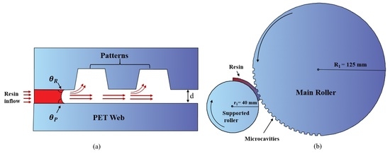
To analyze the filling process in R2R-UV imprinting, different models were studied by considering the flow of UV resin in a straight channel as shown in Figure 1a. However, these models have limitations because they did not include the whole physics of the problem. The filling process of UV resin in roll-to-roll imprinting is shown in Figure 1b. One of the major problems of the bubble defect is the contact of the UV resin with the imprint mold. If the contact angles are not set in the appropriate range, the bubble defects continuously appear in the imprinting process. When UV resin touches the imprint mold during the imprint process, some backflow of the UV resin occurs before applying the nip force. If backflow does not fill the pervious cavities, then bubble entrapment prevails during the imprinting process. Thus, contact angles set in the appropriate range make the optimization of the R2R-UV imprinting process possible. A two-dimensional model with open-channel boundary conditions was constructed to optimize the filling process into the microcavities. The schematic of the R2R-UV imprinting model is shown in Figure 2, which includes the movement of the PET web from left to right with the help of a supported roller together with the rotation of the imprint mold. Note that the rotational movement of the roller is set in the same manner as the linear movement of the PET web to ensure the system’s mechanical accuracy. A complete simulation model of rectangular patterns with a tapering angle of 5° with open-channel boundary conditions is shown in Figure 3. The resin enters from the left (inlet) and moves toward the imprint roller aided by the movement of the PET web. The PET web is considered as a stretched wall above the backup roller and set as a moving wall boundary condition. In this model, we analyzed more realistically the UV resin filling by direct contact of the resin with the imprint mold. The computational domain is considered as a single body in which the imprint roller is considered as a rotating wall boundary condition. The imprint roller wall consists of different types of rectangular and V-shape micropatterns moving at a specific rotational speed during UV imprinting. The rotation of the imprint roller wall is updated with time relative to the other wall’s motion. The open-channel VOF model divides the air and resin phases in the computational domain. The resin thickness above the PET web and the velocity of the resin are also defined in the computational domain of the open-channel VOF model. Additionally, pressure boundary conditions are set as atmospheric at the inlet and outlet of the domain to analyze the filling process under the environmental conditions. The simulation parameters for different simulations are defined in Table 1. The parameters include the height and width, inlet velocity, thickness, viscosity, density of the UV resin and contact angles. The contact angle between UV resin and the PET web is defined as , and the contact angle between UV resin and the imprinting mold is defined as .
3. Experimental Setup
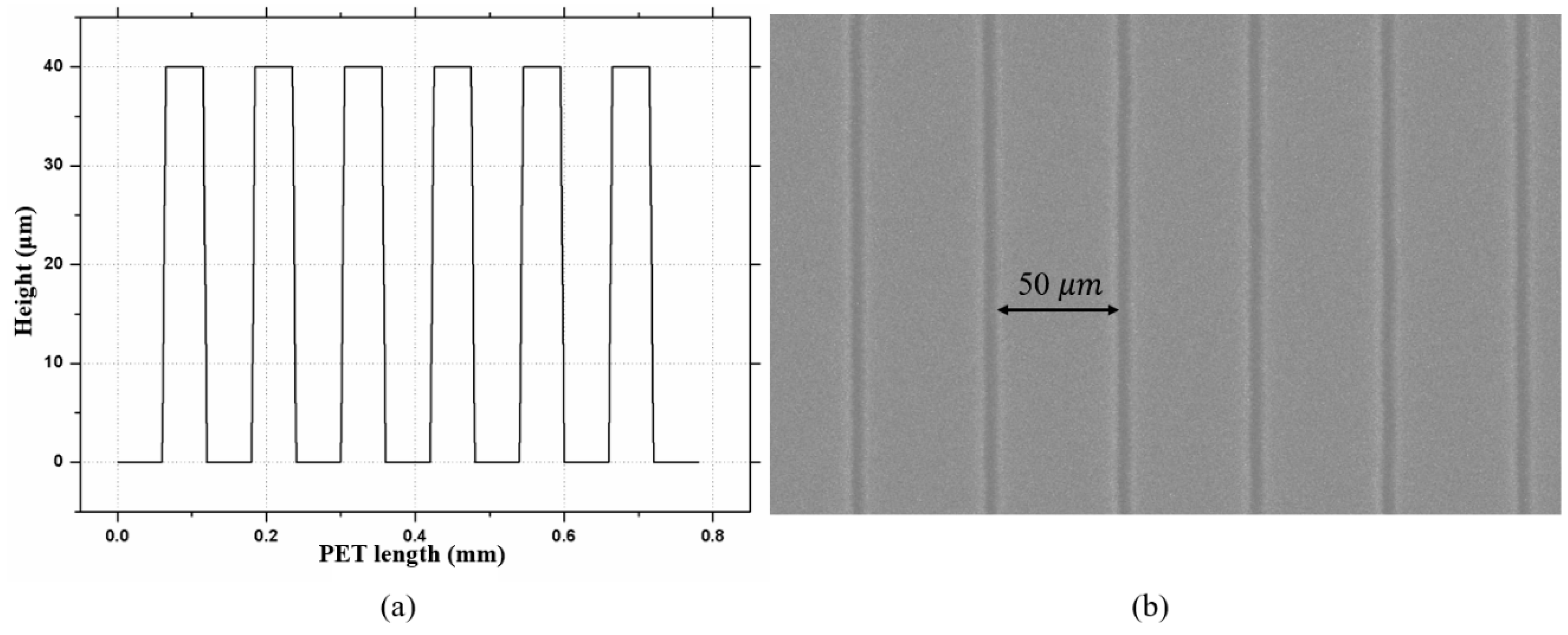
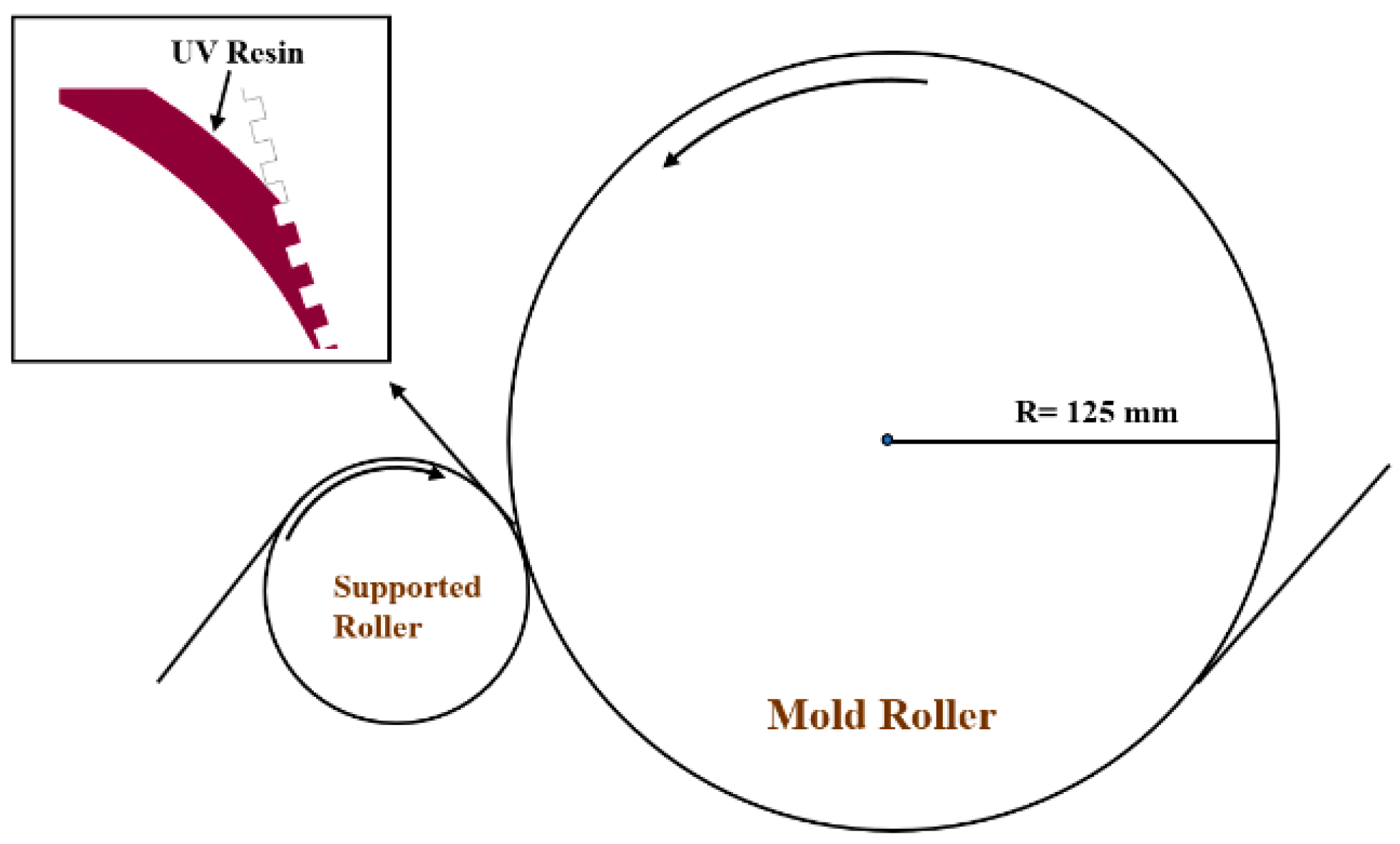
The R2R-UV imprinting system is shown in Figure 4a. The experimental system consists of different modules other than the imprinting module. These modules provide support for the imprinting module to conduct the imprinting process properly. The device contains seven modules, namely, unwinding module, tension module, dispensing module, coating module, imprinting module, adjusting module, and rewinding module. The unwinding module supplies the PET film without coating. The thickness of the PET film (Kolon polyester film, Daegu, Korea) used as a substrate was 125 μm. The tension module is responsible for creating tension at the two ends of the PET film so that the film moves properly into the imprinting process. The dispensing module consists of a resin cylinder that can possibly evacuate the bubbles from the resin and drop-casting unit [15]. The adjusting module adjusts the wrap angle between the stamp roller and the PET substrate.
The main module of the device is the imprinting module that consists of a supported roller with a diameter of 80 mm, a stamp roller with a diameter of 250 mm having a rectangular pattern with a tapering angle 5° and a UV light underneath the rollers that cures the resin. The magnified view of the imprinting process is shown in Figure 4b.
The height and width of the line patterns were 40 and 50 μm, respectively. In the imprinting module, the imprinting force was applied between the stamp roller and the supported roller to fill the resin into the microcavities and, after filling, the UV- light cured and solidified the resin. The rewinding module pulled back the imprinted pattern onto the PET substrate. Further, these patterns were analyzed by scanning electron microscopy (SEM, SNE-3200M, SEC Co., Ltd., Suwon, Gyeonggi, Korea) to check the pattern shape and size on the PET substrate. During the experiments, the resin was dispensed by drop-casting unit evenly onto the PET web film and this method made the coating more uniform than the original coating method (roll coating method). The UV light was a light-emitting diode (LICHTZEN, Gunpo, Korea) used to cure the resin under the imprinted module. The UV lamp threw the light at the focus point with an intensity of 800 mW/cm2 and cured the resin at a wavelength of 365 ± 5 nm. The resin used in the experiments was produced by Minuta Technology Co., Ltd. (MINS-311R, Osan, Korea; viscosity: 0.1 Pas at 25 °C).
4. Results and Discussion
R2R-UV imprint model simulations for optimal filling depend on different parameters such as contact angles, pattern shape, speed of the filling, aspect ratios, and viscosity. To optimize the filling process, different simulations were performed in this study considering different parameters; also, in addition, the experiments were conducted considering the numerical simulations. A complete setup was studied during the numerical simulations. An imprint mold with rectangular patterns and rectangular patterns with a tapering angle and V-shape patterns with different aspect ratios (i.e., 0.75, 0.8) were thoroughly studied with this numerical model.
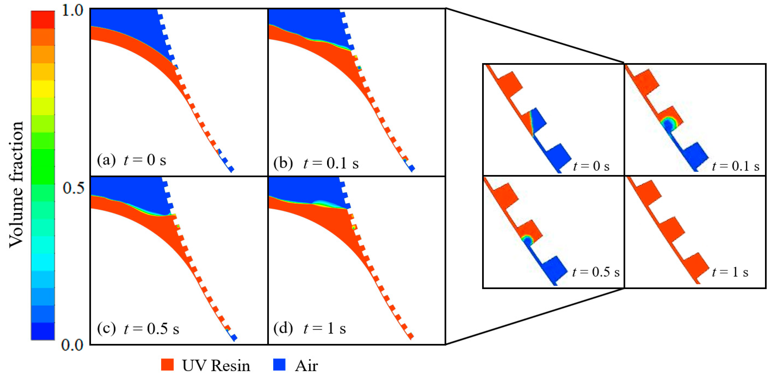
Figure 5 shows the filling process into rectangular microcavities at different time-steps. Figure 5a shows the UV resin flow field and the air above the UV resin at time t = 0 s. When the imprint mold starts to rotate, the PET web delivers the resin into the microcavities at the same time. At a specific rotational velocity of the imprint mold, the air starts to escape into the microcavities, which are filled by UV resin. The UV resin flows into the microcavities from the two ends of the imprinting mold, called the preceding end and the succeeding end. When UV resin starts to fill the microcavities, some backflow of UV resin occurs at the preceding end of the imprint mold. The UV resin filling at the succeeding end is shown in magnified view in Figure 5b–d. At time t = 0.1 s, UV resin fills the first microcavity and leaves the microcavity with incomplete filling as shown in Figure 5b. Over time, UV resin fills the first microcavity completely and starts filling the second microcavity at t = 0.5 s, as shown in Figure 5c. The second microcavity is completely filled with UV resin at time t = 1 s, as shown in Figure 5d. In Figure 5b–d, it can be seen at the preceding end that the backflow of UV resin does not fill the rectangular microcavities, which can cause bubble defects at any stage of the imprinting process. In our numerical model, the microcavities on the imprint mold change their reference position with respect to time, so these bubble defects can be ignored, but at any stage of the imprinting process these bubble defects may affect the quality of the final product. Therefore, we tried to resolve this issue by using a tapering angle for the rectangular microcavities.
Figure 6 shows the filling process into rectangular microcavities with a tapering angle of at different time-steps. Figure 6a shows the UV resin flow field at time t = 0 s. Figure 6b–d represents the UV resin filling into microcavities at the preceding and succeeding ends of the imprint mold at time t = 0.1 s, t = 0.5 s, and t = 1 s, respectively. It can be seen that UV resin fills the microcavities successfully at the preceding and succeeding ends. The contact angles and PET web speed for rectangular patterns, with a tapering angle of 5°, were kept the same as for the rectangular pattern’s simulations as displayed in Figure 5. The suitable contact angles measured for the filling process are and , where and represent the contact angle of resin to the imprint roller and the contact angle of resin to the PET web, respectively. The contact angle between the resin and imprint roller is very important during the filling process in numerical simulations and its values differ with respect to pattern shape; therefore, we keep both contact angles within a feasible range to obtain the complete filling into microcavities. It is also noted that the contact angle between the resin and the roller should be in a specific range to optimize the filling process rather than the contact angle between the resin and the PET web. The PET web speed noted in this study for successful filling into microcavities is 24.2 mm/s.
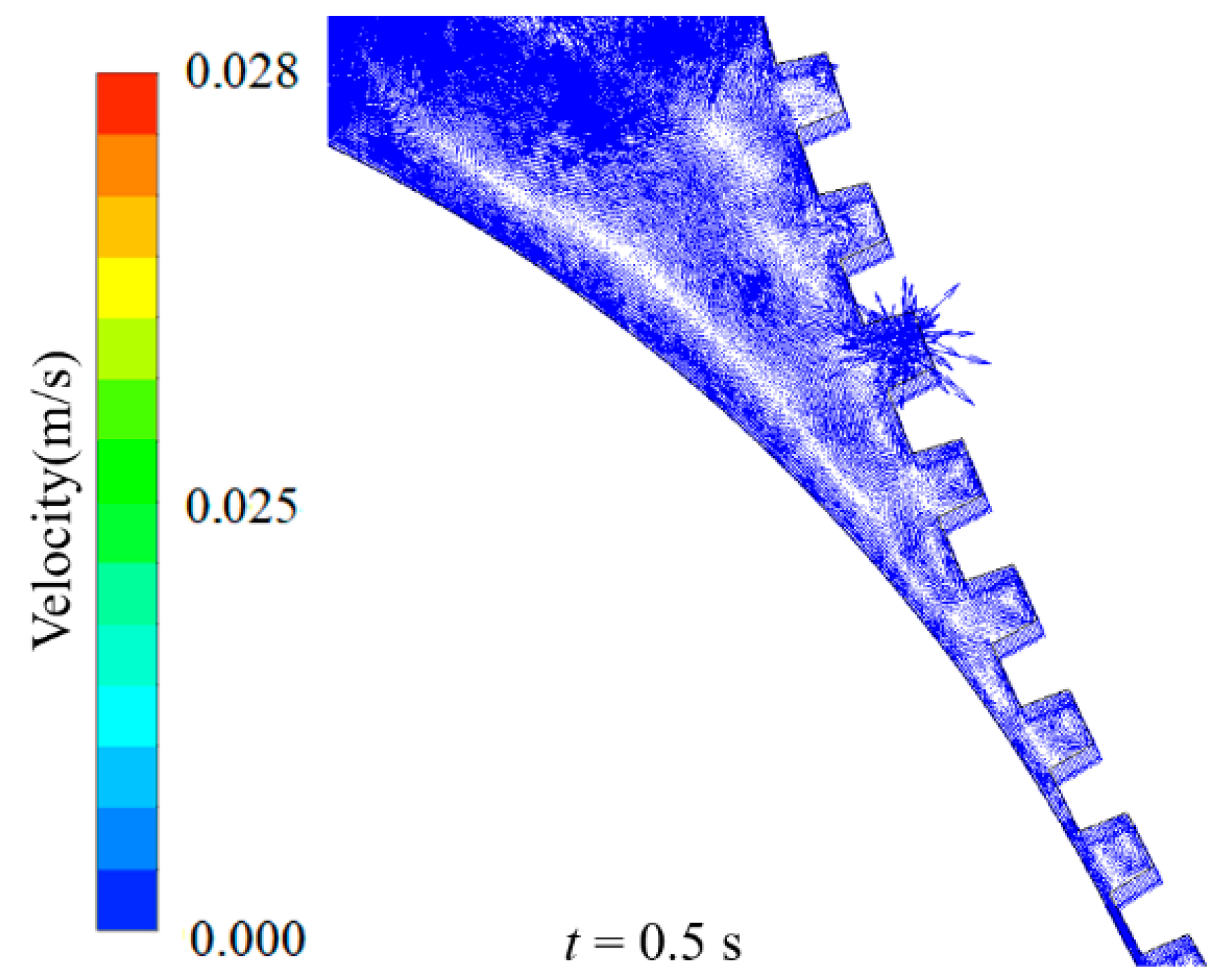
Figure 7 shows the contours for the velocity vector distribution in the flow field of resin–air phases, the rotational movement of the roller, and the successful filling of backflow into the microcavities. It can be seen from the velocity vectors that resin flows from the two ends of the imprint roller. The vortices [22,23] show that resin slows down for some time and waits for the air to escape into the microcavities and, after escaping, the resin fills the microcavities. Figure 8 shows the incomplete filling at the rotating mold’s high speed. When UV resin enters into the microcavities at high speed, it leaves the microcavities with incomplete filling. It can be seen from Figure 8 that the UV resin fails to fill the cavities from both sides of the imprint mold.
Figure 9 represents the steady filling at different rotation speeds or PET web speeds. Different numerical simulations were conducted at high speed and it was observed that, above a specific speed, the UV resin left the microcavities with incomplete filling.
Figure 10 represents the backflow incomplete filling of cavities from time t = 0.02 to 0.3 s at a PET web speed of 54.5 mm/s. It is evident that the air cannot escape at that speed and that bubbles formed into the cavities. It can be concluded that air entrapment occurs if the system’s speed increases beyond a barrier speed.
Figure 11 presents the resin percentage with time at a PET web speed of 24.2 mm/s. UV resin starts to move into the microcavity at t = 0 s. It can be seen at t = 0.1 s that the resin fills the cavity to approximately 65%. With a continuous supply of the UV resin with time, this air entrapment starts decreasing, and it vanishes at t = 0.45 s.
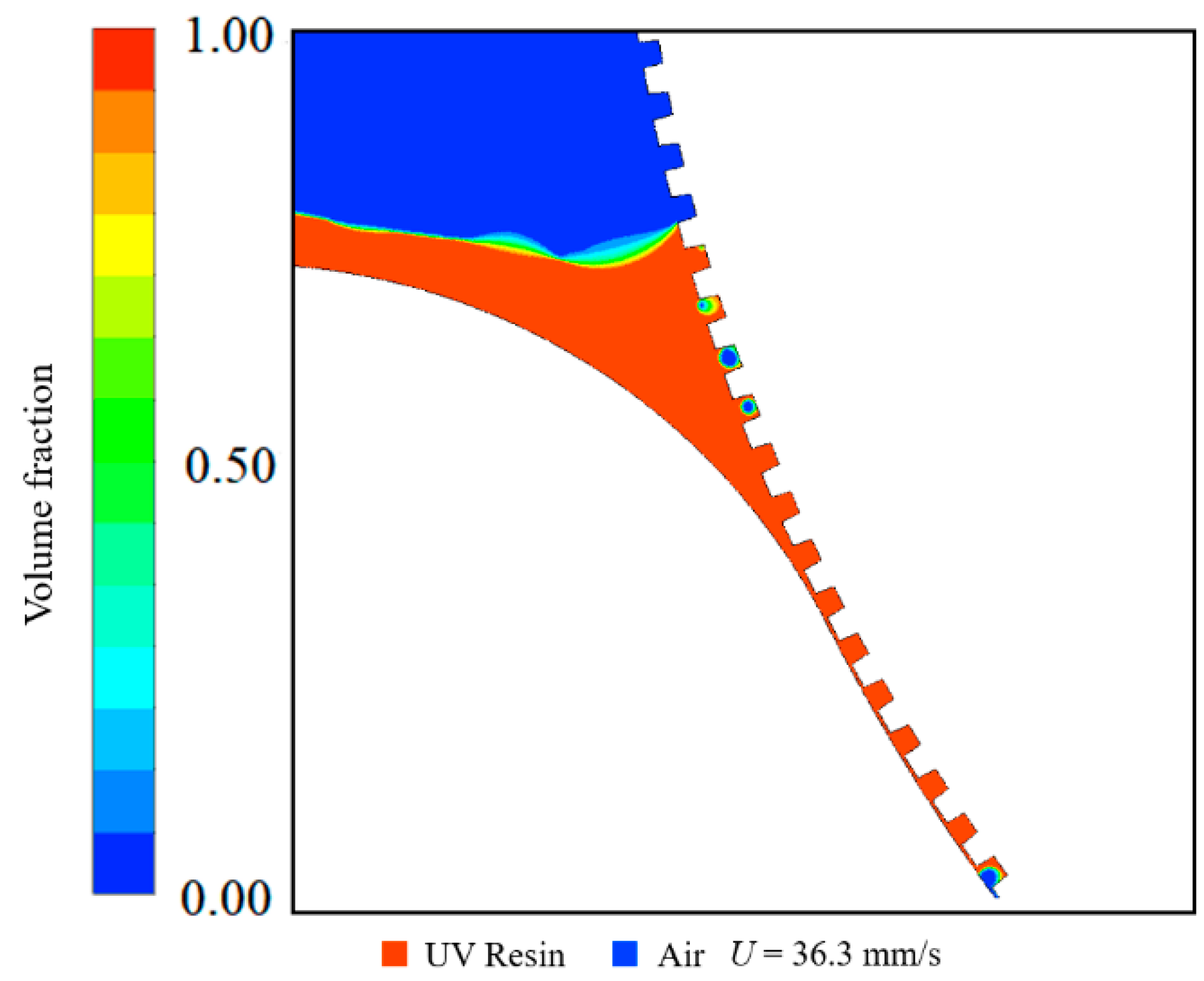
Figure 12a–d represents the numerical simulation results for V-shape patterns with an aspect ratio of 0.75 at different time-steps and considering the previously studied numerical simulation parameters. The resin fills the V-shape microcavities at the optimal speed discussed in a previous study [16]. These results validate our numerical model based on a single zone with a rotating imprinting wall as shown in Figure 3. Furthermore, by removing the interface between the outer part and the mold cavities, resin filling behavior can be observed more realistically. The numerical simulations also show that, by increasing the tapering angle, the air easily escapes from the microcavities and they fill easily with resin. Therefore, it is evident that pattern shape is also responsible for cavities filling during the R2R-UV imprinting process. The V-shape patterns with an aspect ratio of 0.75 have a tapering angle of 35°.
5. Conclusions
In this study, a novel approach was used to optimize the R2R imprinting system. The numerical multi-phase model based on a single zone with open-channel boundary conditions was proposed. The UV resin filling into a single mold cavity was also analyzed by the proposed numerical model. Different patterns were considered to validate the technique. The results show that by increasing the tapering angle, UV resin easily fills the microcavities with a resin–mold contact angle of . We also investigated the situation where, at high imprinting speed, backflow of UV resin occurs and resin does not fill the microcavities toward the succeeding end of the imprinting mold. For a complete UV resin filling process, the maximum noted web speed is 24.2 mm/s. The proposed model can be used for optimizing any R2R-UV imprinting system with high accuracy. In summary, these results can play a significant role in continuous R2R-UV imprinting without defects.
Author Contributions
The formal analysis, conceptualization, and methodology were done by U.T. and M.A.K. The writing—original draft, software, and investigation was accomplished by U.T. The visualization, writing—review and editing was completed by M.A.K. This work was supervised and by M.Y.J.
Funding
This work was supported by the Technology Innovation Program (N0002310) funded by the Ministry of Trade, Industry, and Energy (MOTIE, Korea).
Conflicts of Interest
The authors declare no conflict of interest.
References
- Ahn, S.; Cha, J.; Myung, H.; Kim, S.M.; Kang, S. Continuous ultraviolet roll nanoimprinting process for replicating large-scale nano-and micropatterns. Appl. Phys. Lett. 2006, 89, 213101. [Google Scholar] [CrossRef]
- Maury, P.; Turkenburg, D.; Stroeks, N.; Giesen, P.; Barbu, I.; Meinders, E.; Van Bremen, A.; Iosad, N.; Van der Werf, R.; Onvlee, H. Roll-to-roll UV imprint lithography for flexible electronics. Microelectron. Eng. 2011, 88, 2052–2055. [Google Scholar] [CrossRef]
- Ahn, S.H.; Kim, J.S.; Guo, L.J. Bilayer metal wire-grid polarizer fabricated by roll-to-roll nanoimprint lithography on flexible plastic substrate. J. Vac. Sci. Technol. B Microelectron. Nanometer Struct. Process. Meas. Phenom. 2007, 25, 2388–2391. [Google Scholar] [CrossRef]
- Maury, P.; Stroeks, N.; Wijnen, M.; Tacken, R.; van der Werf, R. Roll-to-roll UV imprint for bottom-up transistor fabrication. J. Photopolym. Sci. Technol. 2011, 24, 43–45. [Google Scholar] [CrossRef]
- Kang, M.G.; Park, H.J.; Ahn, S.H.; Guo, L.J. Transparent Cu nanowire mesh electrode on flexible substrates fabricated by transfer printing and its application in organic solar cells. Sol. Energy Mater. Sol. Cells 2010, 94, 1179–1184. [Google Scholar] [CrossRef]
- Ahn, S.H.; Guo, L.J. Large-area roll-to-roll and roll-to-plate nanoimprint lithography: A step toward high-throughput application of continuous nanoimprinting. ACS Nano 2009, 3, 2304–2310. [Google Scholar] [CrossRef] [PubMed]
- Smolka, M.; Haase, A.; Palfinger, U.; Nees, D.; Kuna, L.; Hesse, J.; Stadlober, B.; Geidel, S.; Nestler, J.; Ladenhauf, N. Roll-to-Roll pilot line for large-scale manufacturing of microfluidic devices. In Proceedings of the Single-Use Technologies II: Bridging Polymer Science to Biotechnology Applications, Tomar, Portugal, 7–10 May 2017. [Google Scholar]
- Yi, P.; Zhang, C.; Peng, L.; Lai, X. Flexible silver-mesh electrodes with moth-eye nanostructures for transmittance enhancement by double-sided roll-to-roll nanoimprint lithography. RSC Adv. 2017, 7, 48835–48840. [Google Scholar] [CrossRef] [Green Version]
- Jain, A.; Bonnecaze, R.T. Fluid management in roll-to-roll nanoimprint lithography. J. Appl. Phys. 2013, 113, 234511. [Google Scholar] [CrossRef]
- Peng, L.; Wu, H.; Yi, P.; Lai, X. Study on bubble defects in roll-to-roll UV imprinting process for micropyramid arrays II: Numerical study. J. Vac. Sci. Technol. B Nanotechnol. Microelectron. Mater. Process. Meas. Phenom. 2016, 34, 051203. [Google Scholar] [CrossRef]
- Song, X.; Shan, X.; Chow, S.; Deng, X.; Teo, W. Numerical and experimental study of the filling stage of roll-to-roll UV embossing process with micro features. Microsyst. Technol. 2015, 21, 1729–1738. [Google Scholar] [CrossRef]
- Ye, H.; Shen, L.; Li, M.; Zhang, Q. Bubble defect control in low-cost roll-to-roll ultraviolet imprint lithography. Micro Nano Lett. 2014, 9, 28–30. [Google Scholar] [CrossRef]
- Ye, H.; Shen, L.G.; Tao, B.; Li, M.J. A study of the bubbles in UV micro roll-to-roll imprinting. Int. Polym. Process. 2014, 29, 602–606. [Google Scholar] [CrossRef]
- Lopes, A.V.B.; Thiele, U.; Hazel, A.L. On the multiple solutions of coating and rimming flows on rotating cylinders. J. Fluid Mech. 2018, 835, 540–574. [Google Scholar] [CrossRef]
- Tahir, U.; Kamran, M.A.; Jang, M.H.; Jeong, M.Y. Thin-film coating on cylinder for fabrication of cylindrical mold: Roll-to-roll nano-imprint lithography. Microelectron. Eng. 2019, 211, 5–12. [Google Scholar] [CrossRef]
- Zhou, Y.; Li, M.; Shen, L.; Ye, H.; Wang, J.; Huang, S. Effect of resin accumulation on filling process in roll-to-roll UV imprint lithography. J. Vac. Sci. Technol. B Nanotechnol. Microelectron. Mater. Process. Meas. Phenom. 2017, 35, 031602. [Google Scholar] [CrossRef]
- Anderson, J.D.; Wendt, J. Computational Fluid Dynamics; Springer: Berlin/Heidelberg, Germany, 1995; Volume 206. [Google Scholar]
- Yoo, D.; Seok, J.M.; Kim, N.W. Three-dimensional numerical investigations of air bubble defects during antireflective pattern fabrication via ultraviolet nanoimprint lithography. J. Vac. Sci. Technol. B Nanotechnol. Microelectron. Mater. Process. Meas. Phenom. 2014, 32, 061602. [Google Scholar] [CrossRef]
- Hirt, C.W.; Nichols, B.D. Volume of fluid (VOF) method for the dynamics of free boundaries. J. Comput. Phys. 1981, 39, 201–225. [Google Scholar] [CrossRef]
- Versteeg, H.K.; Malalasekera, W. An Introduction to Computational Fluid Dynamics: The Finite Volume Method; Pearson Education: London, UK, 2007. [Google Scholar]
- Fluent, A. Release 16.0, Theory Guide; ANSYS. Inc.: Canonsburg, PA, USA, 2015. [Google Scholar]
- Hong, K.S.; Shah, U.H. Vortex-induced vibrations and control of marine risers: A review. Ocean Eng. 2018, 152, 300–315. [Google Scholar] [CrossRef]
- Shah, U.H.; Hong, K.S. Active vibration control of a flexible rod moving in water: Application to nuclear refueling machines. Automatica 2018, 93, 231–243. [Google Scholar] [CrossRef]
Figure 1.
(a) Microcavity filling with ultraviolet (UV) resin between two parallel plates and contact angle of resin with stamp roller and polyethylene terephthalate (PET) web; (b) microcavity filling in the domain of the third quadrant in the roll-to-roll imprinting process.
Figure 1.
(a) Microcavity filling with ultraviolet (UV) resin between two parallel plates and contact angle of resin with stamp roller and polyethylene terephthalate (PET) web; (b) microcavity filling in the domain of the third quadrant in the roll-to-roll imprinting process.
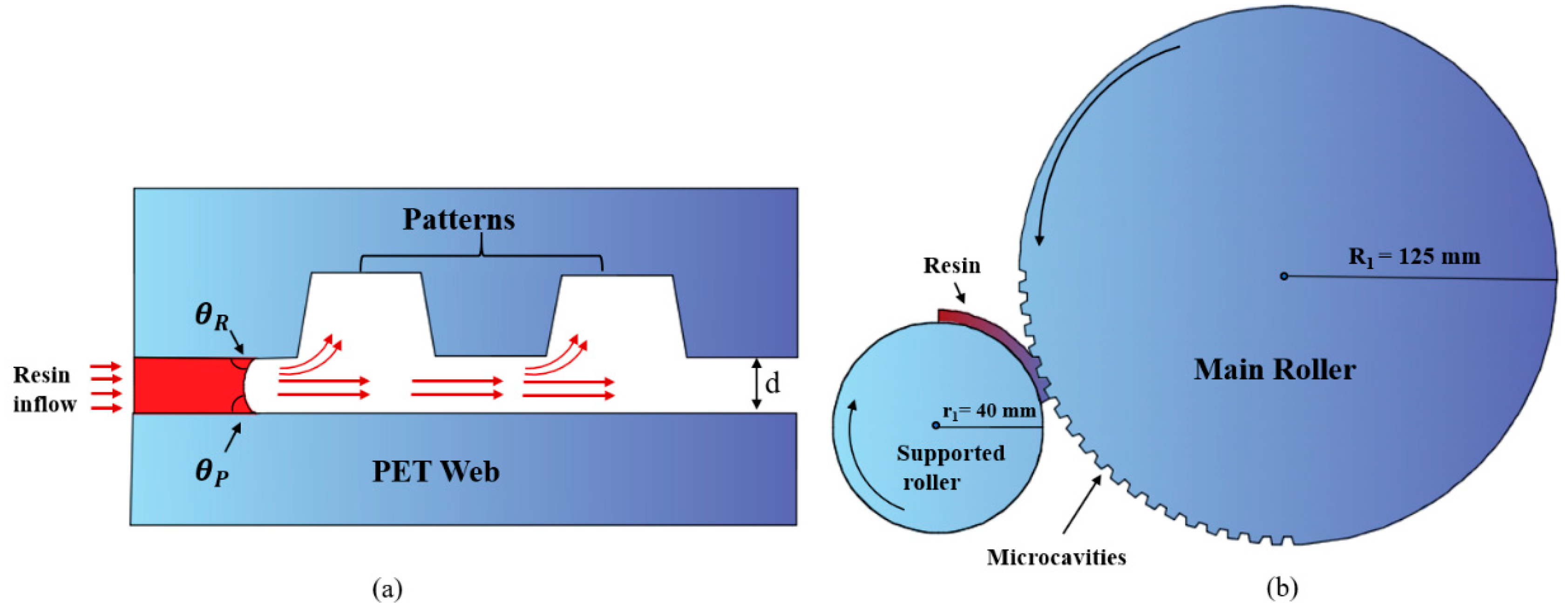
Figure 2.
Schematic diagram of imprinting module and UV resin contact with the roller mold in the magnified view.
Figure 2.
Schematic diagram of imprinting module and UV resin contact with the roller mold in the magnified view.

Figure 3.
Two-dimensional multiphase model based on a single zone with open-channel boundary conditions and magnified view of the air–resin interface with direct contact of resin with the roller mold.
Figure 3.
Two-dimensional multiphase model based on a single zone with open-channel boundary conditions and magnified view of the air–resin interface with direct contact of resin with the roller mold.
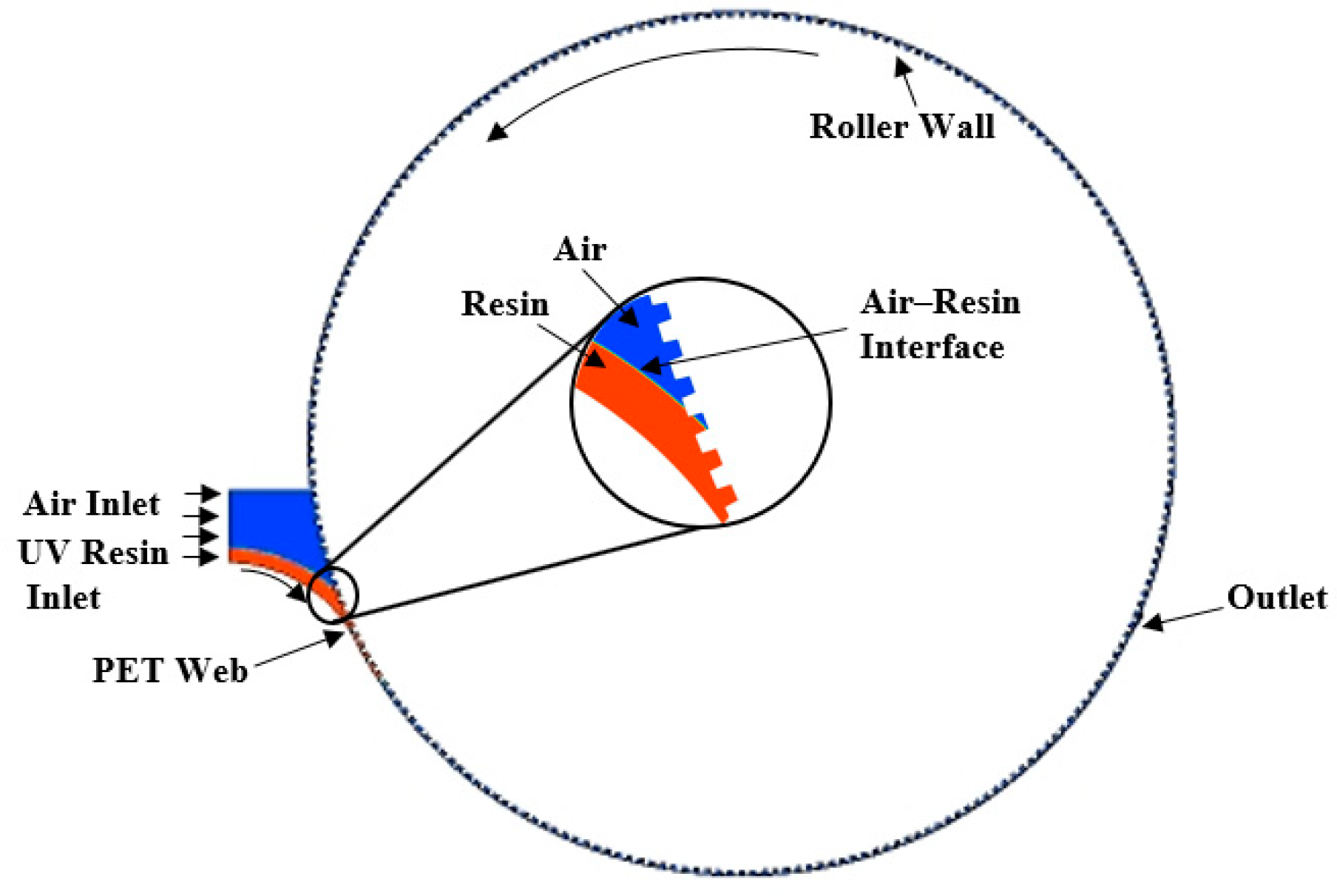
Figure 4.
(a) R2R-UV experimental setup with drop-casting dispensing unit; (b) magnified view of imprinting module with UV light underneath the imprint rollers.
Figure 4.
(a) R2R-UV experimental setup with drop-casting dispensing unit; (b) magnified view of imprinting module with UV light underneath the imprint rollers.
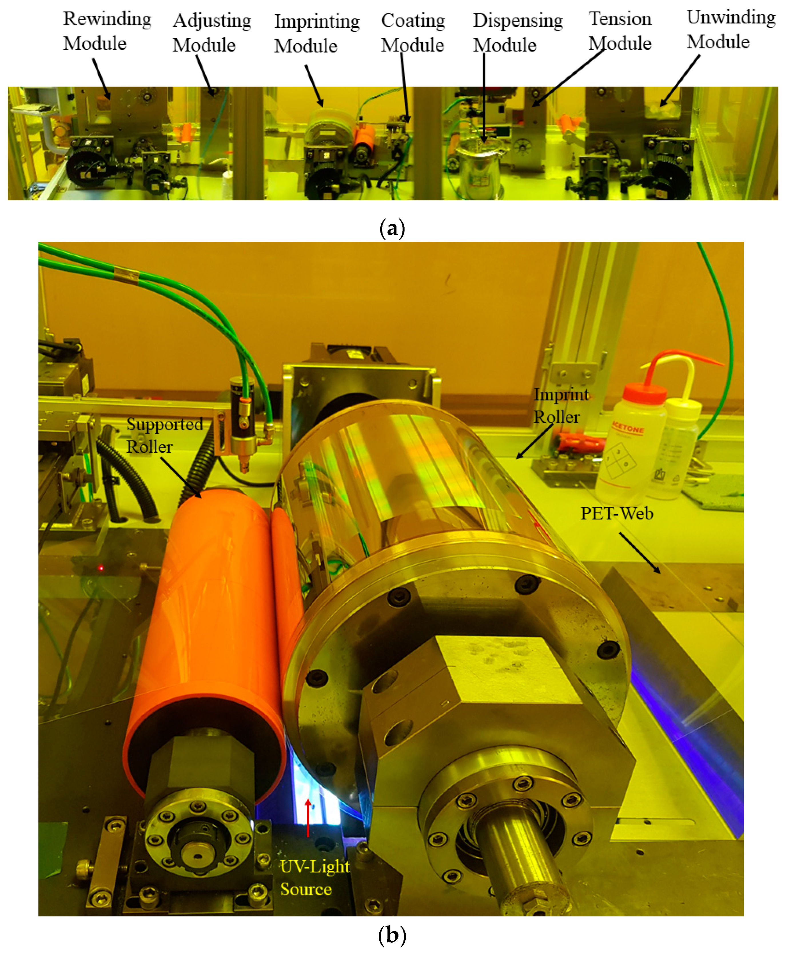
Figure 5.
UV resin incomplete backflow into the rectangular microcavities at different times: (a) t = 0 s, (b) t = 0.1 s, (c) t = 0.5 s, and (d) t = 1 s, at a PET web speed of 24.2 mm/s. The magnified view of complete filling on the other end of the roller at respective times (, ).
Figure 5.
UV resin incomplete backflow into the rectangular microcavities at different times: (a) t = 0 s, (b) t = 0.1 s, (c) t = 0.5 s, and (d) t = 1 s, at a PET web speed of 24.2 mm/s. The magnified view of complete filling on the other end of the roller at respective times (, ).
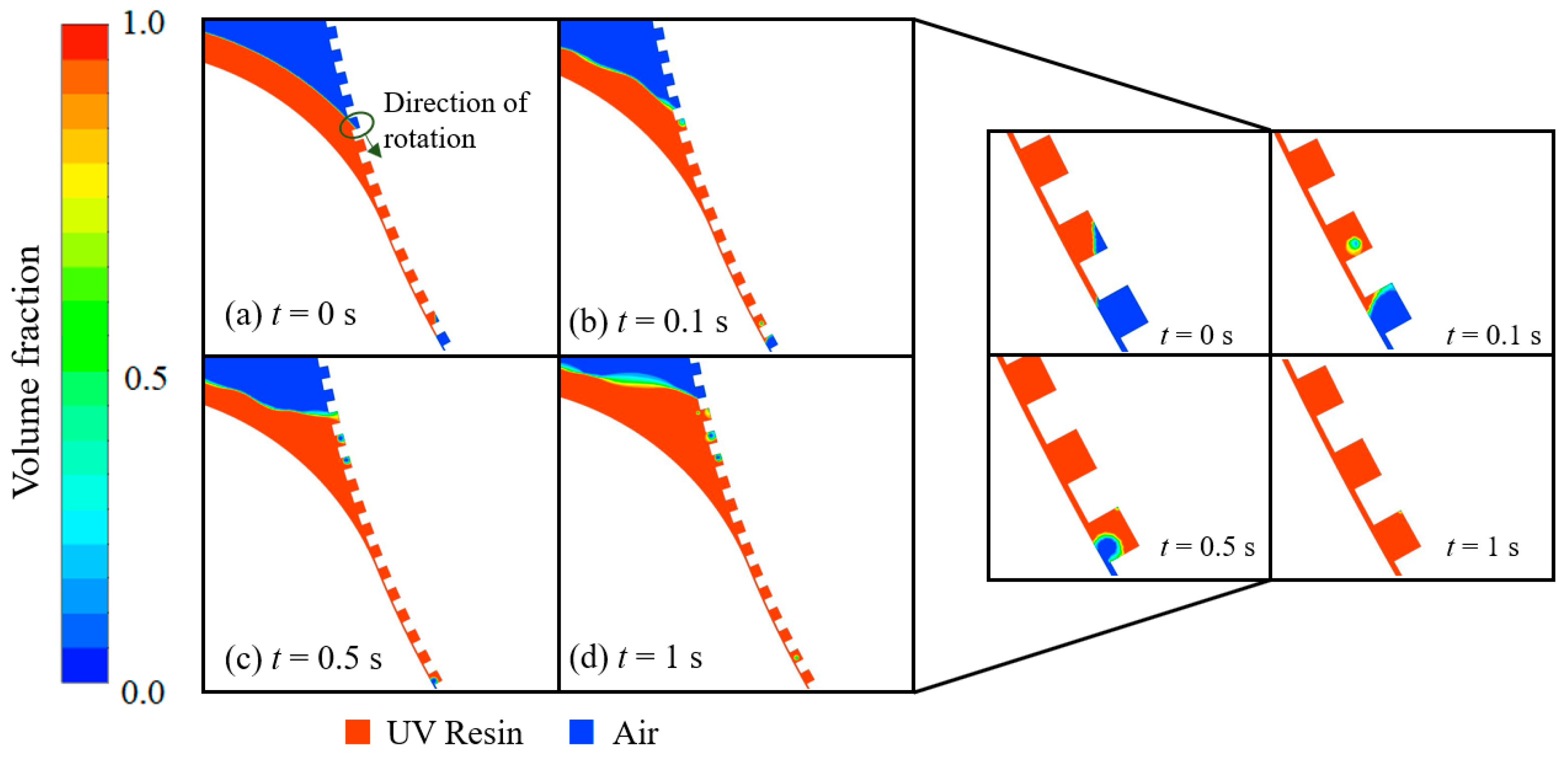
Figure 6.
UV resin complete filling into the rectangular microcavities with a tapering angle of 5° at two ends of the roller mold at different times: (a) t = 0 s, (b) t = 0.1 s, (c) t = 0.5 s, and (d) t= 1 s, at a PET web speed of 24.2 mm/s (, ).
Figure 6.
UV resin complete filling into the rectangular microcavities with a tapering angle of 5° at two ends of the roller mold at different times: (a) t = 0 s, (b) t = 0.1 s, (c) t = 0.5 s, and (d) t= 1 s, at a PET web speed of 24.2 mm/s (, ).

Figure 7.
Velocity vectors of the moving and rotating walls at time t = 0.5 s, at a web speed of 24.2 mm/s.
Figure 7.
Velocity vectors of the moving and rotating walls at time t = 0.5 s, at a web speed of 24.2 mm/s.

Figure 8.
UV resin incomplete filling into the rectangular microcavities with a tapering angle of 5° at two ends of the roller mold at a PET web speed of 36.3 mm/s and t = 1 s (, ).
Figure 8.
UV resin incomplete filling into the rectangular microcavities with a tapering angle of 5° at two ends of the roller mold at a PET web speed of 36.3 mm/s and t = 1 s (, ).

Figure 9.
UV resin filling from uniform to non-uniform at different PET web speeds.
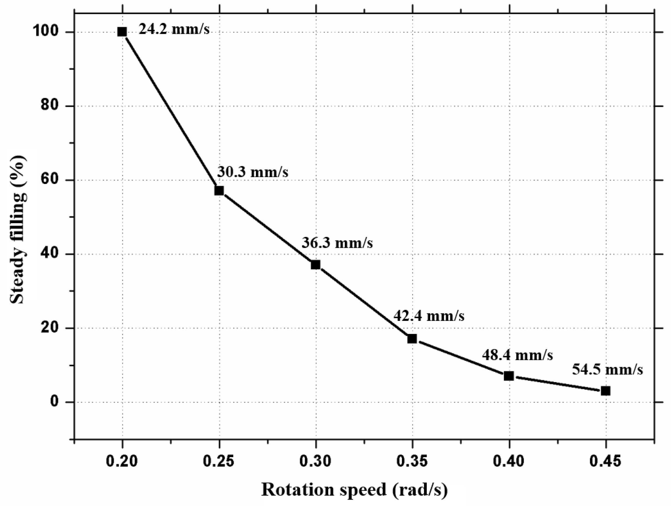
Figure 10.
UV resin incomplete filling of backflow at different times at a PET web speed of 54.5 mm/s.
Figure 10.
UV resin incomplete filling of backflow at different times at a PET web speed of 54.5 mm/s.
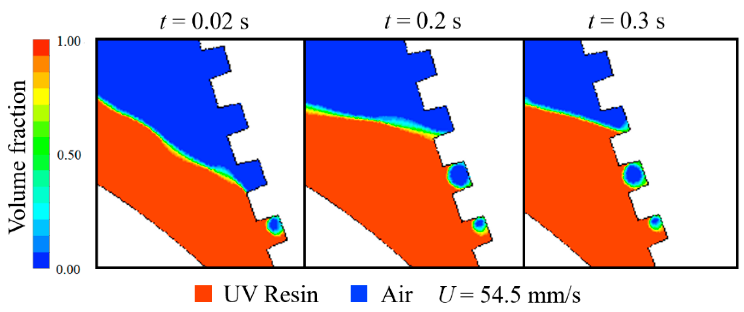
Figure 11.
UV resin filling percentage into single microcavity at different times at a PET web speed of 24.2 mm/s.
Figure 11.
UV resin filling percentage into single microcavity at different times at a PET web speed of 24.2 mm/s.
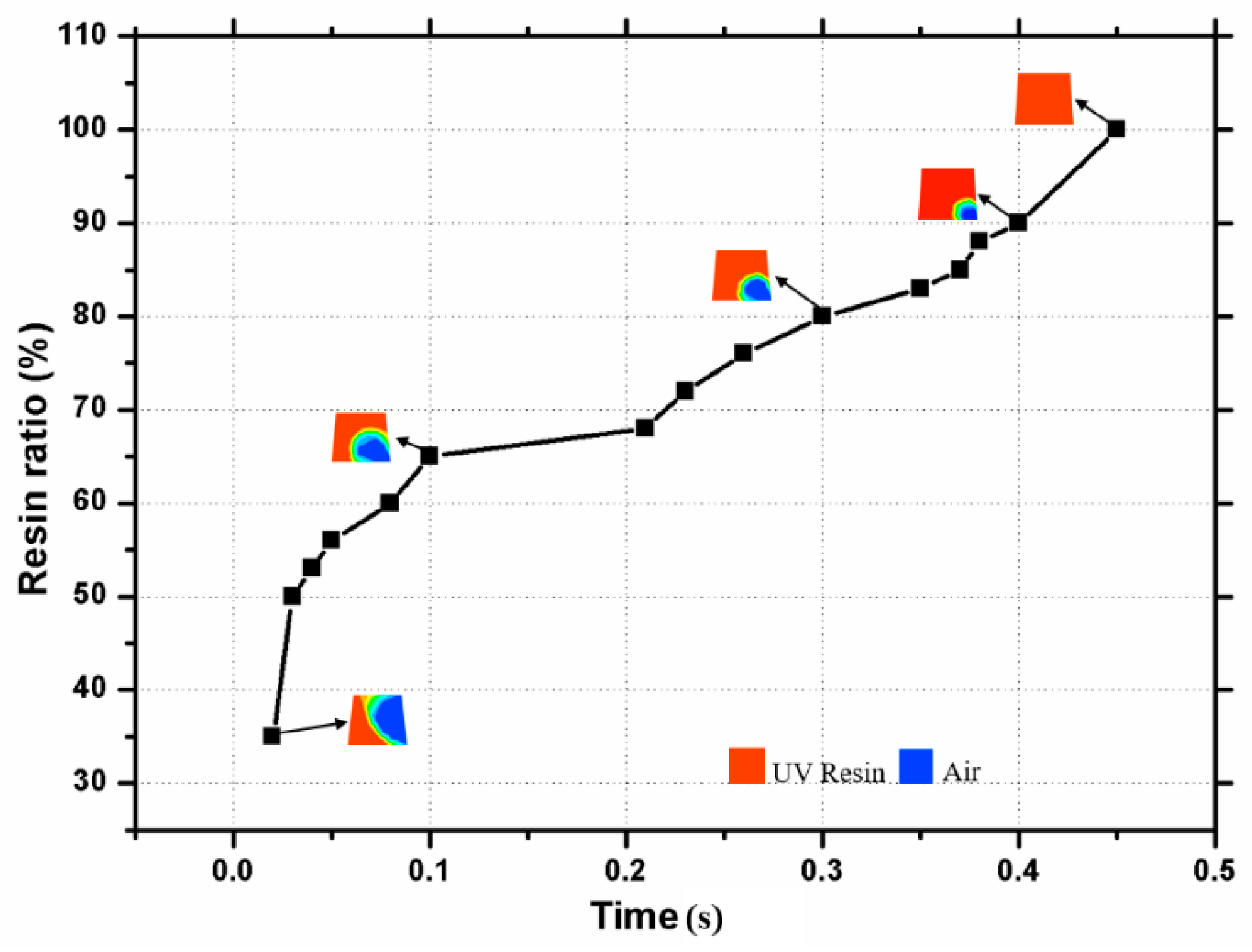
Figure 12.
UV resin complete filling into V-shape patterns at the two ends of the roller mold at a PET web speed of 1.81 mm/s (, ).
Figure 12.
UV resin complete filling into V-shape patterns at the two ends of the roller mold at a PET web speed of 1.81 mm/s (, ).
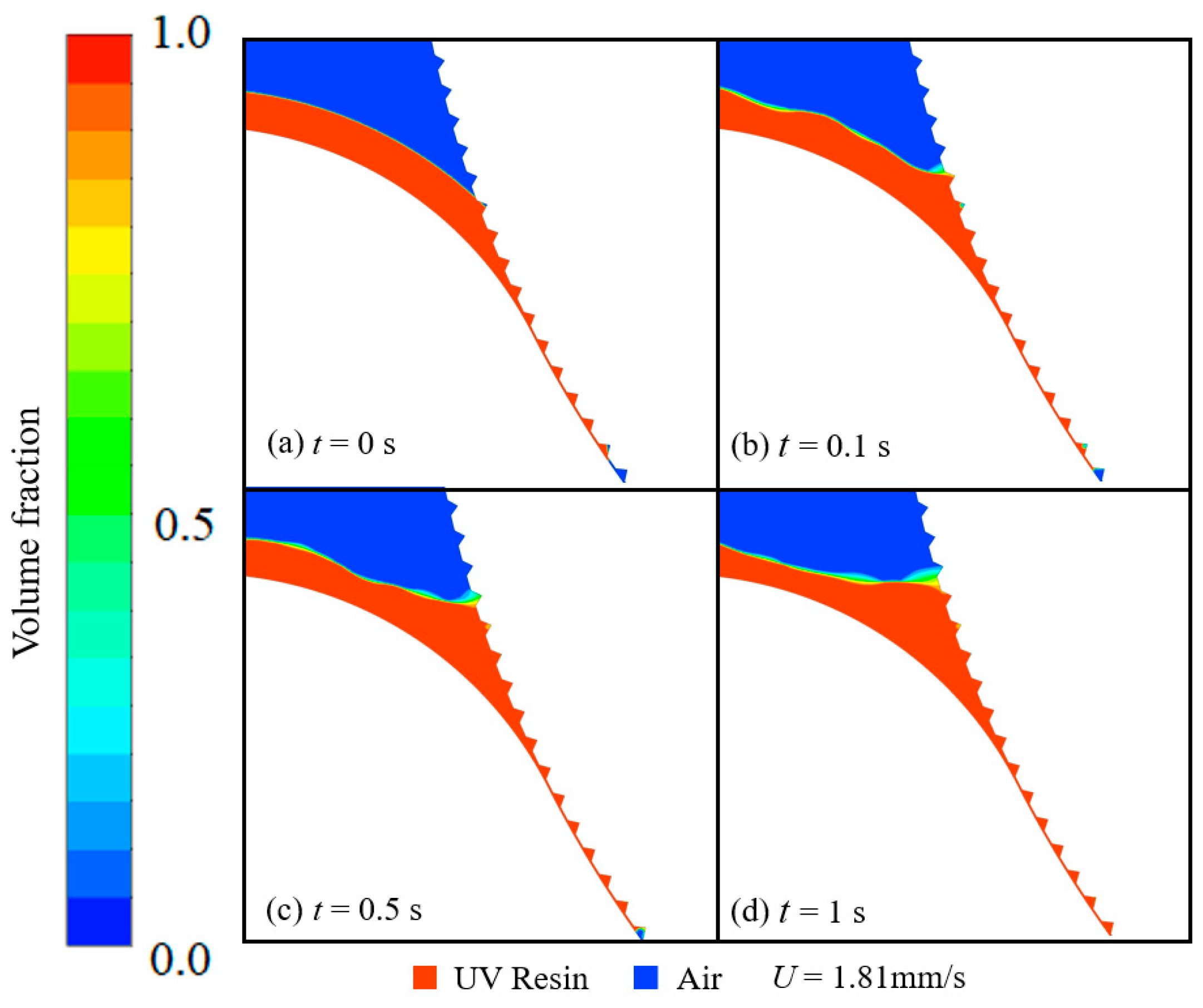
Figure 13.
Experimental results: (a) amplifications of the sample profile of the experiment; (b) SEM image of bubble-free imprinting at a PET web speed of 24.2 mm/s.
Figure 13.
Experimental results: (a) amplifications of the sample profile of the experiment; (b) SEM image of bubble-free imprinting at a PET web speed of 24.2 mm/s.

Table 1.
Numerical simulation parameters.
| Variables | Values |
|---|---|
| Cavity height (H) | 30–40 μm |
| Cavity width (W) | 40–50 μm |
| Density | 1220–1470 kg/cm3 |
| Viscosity | 0.1–0.45 Pas |
| Contact angle | 15°–20° |
| Contact angle | 50°–70° |
| PET web speed | 20–60 mm/s |
| UV resin initial thickness | 70–100 μm |
© 2019 by the authors. Licensee MDPI, Basel, Switzerland. This article is an open access article distributed under the terms and conditions of the Creative Commons Attribution (CC BY) license (http://creativecommons.org/licenses/by/4.0/).
Share and Cite
MDPI and ACS Style
Tahir, U.; Kamran, M.A.; Jeong, M.Y. Numerical Study on the Optimization of Roll-to-Roll Ultraviolet Imprint Lithography. Coatings 2019, 9, 573. https://doi.org/10.3390/coatings9090573
AMA Style
Tahir U, Kamran MA, Jeong MY. Numerical Study on the Optimization of Roll-to-Roll Ultraviolet Imprint Lithography. Coatings. 2019; 9(9):573. https://doi.org/10.3390/coatings9090573
Chicago/Turabian StyleTahir, Usama, Muhammad Ahmad Kamran, and Myung Yung Jeong. 2019. "Numerical Study on the Optimization of Roll-to-Roll Ultraviolet Imprint Lithography" Coatings 9, no. 9: 573. https://doi.org/10.3390/coatings9090573
Note that from the first issue of 2016, this journal uses article numbers instead of page numbers. See further details here.